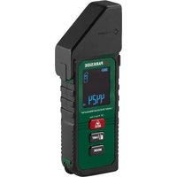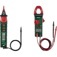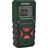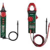
PSM 2 B4 - Measuring equipment PARKSIDE - Free user manual and instructions
Find the device manual for free PSM 2 B4 PARKSIDE in PDF.


User questions about PSM 2 B4 PARKSIDE
0 question about this device. Answer the ones you know or ask your own.
Ask a new question about this device
Download the instructions for your Measuring equipment in PDF format for free! Find your manual PSM 2 B4 - PARKSIDE and take your electronic device back in hand. On this page are published all the documents necessary for the use of your device. PSM 2 B4 by PARKSIDE.
USER MANUAL PSM 2 B4 PARKSIDE
Operating instructions
DE / AT / CH
ZANGEN-AMPEREMETER
Bedienungsanleitung
FR / BE
PINCE AMPÈREMÉTRIQUE
Mode d'emploi
NL / BE
AMPEREMETER-TANG
Gebruiksaanwijzing
CZ
KLEŠTOVÝ MULTIMETR
Návod k obsluze
PL
AMPEROMIERZ CĘGOWY
Instrukcja obsługi
SK
KLIEŠTOVÝ AMPÉRMETER
Návod na obsluhu
ES
PINZA AMPERIMÉTRICA
GB/IE Operating instructions Page 1
text_image
C N L DATE MEN. A- Ω Hz V- CE V- OFF REL SELECT HOLD + 47.5 COM +1 +2 Ω V= Hz - MAX 90% 0% CAT = 80% 0Contents
Introduction 2
Information about these instructions for use .. 2
Intended use 2
Warnings and symbols used .... 2
Safety 4
Basic safety instructions ..... 4
Safety instructions for handling batteries ....7
Operating elements / parts ..... 8
Using the device 9
Check package contents 9
Inserting/replacing the batteries ..... 1 0
Operation and use 10
Switching the device on/off ..... 1 0
Display backlight 1 1
Automatic switch-off function ..... 1 1
Hold measured value 11
Relative mode 12
Removing/attaching the caps ..... 1 3
Measuring DC voltage (V=). 13
Measuring AC voltage (V).....14
Measuring alternating current strength (A)\~14
Measuring resistance (Ω 15
Diode test (→)....15
Continuity test (•) 16
Measuring capacitance (16. 16
Measuring frequency (Hz) 17
Troubleshooting 18
Cleaning 18
Storage ....1
Disposal 19
Disposal of the device 19
Disposal of the packaging ..... 2 0
Disposal of batteries 21
Appendix 22
Technical data 22
Meter specifications....22
Kompernass Handels GmbH warranty .....27
Service 30
Importer 30
Introduction
Information about these instructions for use

Congratulations on the purchase of your new device. You have selected a high-quality device. The operating instructions are part of this device.
They contain important information about safety, usage and disposal. Before using the device, please familiarise yourself with all operating and safety instructions. The device may only be used as described and for the specified application areas. Hand over all documents when passing the device on to third parties.
Intended use
The device is used exclusively for the precise measurement of DC and AC voltage, AC current, resistance, capacitance and frequency and for diode and continuity testing indoors. Observe the laws and regulations of the country in which you are using the device. Commercial or industrial use is not permitted. No liability will be assumed in cases of improper use. No liability will be assumed for damage caused by misuse or improper handling, the use of force or unauthorised modification. The risk is borne solely by the user.
Warnings and symbols used
The following warnings and symbols are used in these operating instructions, on the packaging and on the device:
 | WARNING! A warning with this symbol and the signal word "WARNING" indicates a potentially hazardous situation which could result in death or serious injury if not avoided. |
 | ATTENTION! A warning with this symbol and the signal word "ATTENTION" indicates a potential situation which could result in property damage if not avoided. |
 | Note: A note provides additional information that will assist you in using the device. |
 | Protection class II: Protection by double or reinforced insulation between live and touchable parts. |
 | WARNING! Risk of electric shock! |
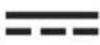 | DC current/voltage |
 | AC current/voltage |
 | DC or AC (direct current or alternating current) |
 | Earthing terminal |
 | The connection and removal of dangerous, energised conductors is permitted. |
Safety
This section contains important safety instructions for handling the device. This device complies with the statutory safety regulations. Improper use may result in personal injury and property damage.
Basic safety instructions
WARNING! To ensure safe operation of the device, follow the safety guidelines set out below:
■ Do not allow children to play with the packaging material! Keep all packaging materials away from children.
- Keep electrical appliances out of the reach of children. People with disabilities should only use electrical appliances within the scope of their abilities. Never allow children or people with disabilities to use electrical appliances unsupervised. They may not recognise potential dangers.
■ Do not use the device in locations where there is a risk of fire or explosion, e.g. in the vicinity of inflammable liquids or gases.
- Check the device before every use to make sure it is in perfect condition. Inspect the insulation in the area of the connections particularly carefully. Do not use the device if it is damaged in any way.
■ Contact a technician if you are not sure how to use or connect the device.
■ To avoid electric shock, do not use the device with the battery compartment cover open. Remove all connected devices before opening the battery compartment cover.
■ Set the device to the correct measurement mode before starting the measurement.
■ For current measurements, switch off the current of the device under test before connecting the device.
■ When working with a circuit, first connect the black test probe to the circuit before connecting the red test probe to the circuit. When disconnecting the test probes from the circuit, first remove the red test probe from the circuit and then the black test probe from the circuit.
■ Never connect a voltage source to the test probes when a current measurement, diode test, resistance measurement or continuity test is selected. Otherwise the device could be damaged.
■ Always remove the test probes from the device under test before changing the measuring mode.
■ The voltage between the measuring device connection points and the earth must not exceed 600 V DC/AC voltage in CAT III.
■ Take particular care when working with voltages above 33 V AC or 70 V DC. Touching electrical conductors at these voltages can lead to a fatal electric shock.
■ To avoid electric shock, do not touch the measuring points directly or indirectly during the measurement. When measuring with the test probes, keep your fingers behind the finger guard.
■ Protect the device from wetness or direct sunlight.
■ Do not expose the device to any extremes of temperature or temperature fluctuations. For example, do not leave it lying in a car for extended periods. After exposure to large temperature fluctuations, allow the device to acclimatise before using it again. The precision of the device can be adversely affected by extreme temperatures or temperature fluctuations.
■ Never immerse the device in water or other liquids, and never expose the device to spraying or dripping water. Use the device only in dry indoor areas.
■ Avoid hefty knocks or dropping the device.
- Do not make any unauthorised modifications or alterations to the device.
■ Never open the device housing. None of the components in the device can be serviced or replaced by the user.
■ Switch the device off immediately and remove the batteries from the device if you notice unusual noises, a burning smell or smoke. Have the device checked by a qualified specialist before using it again.
Safety instructions for handling batteries
⚠ WARNING! Mishandling the batteries can cause fires, explosions, leakages or other hazards!
- Keep batteries out of the reach of children.
■ Make sure that no one can swallow the batteries.
■ If a battery is swallowed, seek medical assistance immediately.
■ Always use the stated battery type.
Never try to recharge non-rechargeable batteries.
■ Remove rechargeable batteries from the device before recharging them.
Do not throw batteries into a fire or water.
■ Never expose batteries to high temperatures or direct sunlight.
Never open or deform batteries.
Do not short-circuit the terminals.
■ Remove depleted batteries from the device and dispose of them safely.
Do not use different types of batteries together or mix new batteries with used batteries.

ays ensure that the batteries alled in the device with the cor- ligned polarity.
If you do not intend to use the device for an extended period, remove the batteries.
■ Check the condition of the batteries at regular intervals. Leaking batteries can cause injuries as well as damage to the device.
■ Always use protective gloves when handling leaking batteries! Clean the battery and device contacts and the battery compartment with a dry cloth. Do not let the chemicals get into contact with your skin and mucous membranes, especially your eyes. In case of contact with chemicals, wash the affected area with plenty of water and immediately seek medical attention.
Operating elements / parts
(For illustrations see fold-out pages)
Fig. A:
① Test clamp
② Control dial
③ SELECT button
4 HOLD button
⑤ Display
6 connection V=Hz+K connection
⑦ connection
⑧ Test probes
8a Test probe cap
8b Connection cap
⑨ Battery compartment cover
⑩ REL button
⑪ Trigger
Fig. B:
⑫ § Absolute value of the detected input voltage ≥ 30 V
13 Automatic switch-off function
14 Units of measurement
15 R Relative mode
16 Continuity test
⑰ Diode test
18 Automatic range
19 Low battery level
20 Hold measured value
②1 DC DC
22 Negative
23 AC
Using the device
Check package contents
- 1× clamp meter
- 2× test probes
- 2× 1.5 V= alkaline batteries of type AAA/Micro/LR03
• These operating instructions - Remove all components from the packaging. Remove all packaging materials and the protective film from the display 5.
Note: Check the package for completeness and signs of visible damage. If the delivery is incomplete or damage has occurred as a result of defective packaging or during transport, contact the customer service hotline (see Service section).
Inserting/replacing the batteries
The device is delivered and operated with two 1.5 V = alkaline batteries, type AAA/Micro/LR03. If the display ⑤ indicates low battery level ⑲, you must replace the batteries.
⚠ WARNING! Switch off the device and remove the test probes ⑧ from the circuit if necessary.
- Loosen the screw on the battery compartment cover ⑨ and remove the battery compartment cover ⑨.
◆ Remove any used batteries and insert two new batteries into the battery compartment. Make sure that the polarity is correct, as indicated in the battery compartment.
♦ Replace the battery compartment cover ⑨ and tighten the screw.
Operation and use
Switching the device on/off
- Turn the control dial ② clockwise from OFF to another position. The display ⑤ switches on automatically.
- Turn the control dial ② anti-clockwise to OFF. The display ⑤ switches off automatically.
Display backlight
- Briefly press and hold the HOLD * button ④ to switch on the backlight.
- Briefly press and hold the HOLD ✪ button ④ again to switch off the backlight.
(i) Note: The backlight switches off automatically after approx. 15 seconds.
Automatic switch-off function
The automatic switch-off function is activated when the symbol ⑬ appears on the display ⑤. The device automatically switches to standby mode if it is not operated for longer than approx. 10 minutes.
◆ Press any button to activate the device from standby mode.
Deactivate the automatic switch-off function:
- Turn the control dial ② clockwise from OFF to another position and hold down the SELECT ③ at the same time.
The symbol ⏻ 13 disappears and the automatic switch-off function is deactivated.
(i) Note: When the device is switched on again, the automatic switch-off function is reactivated.
Hold measured value
◆ Press the HOLD * button ④ to hold the current measured value. The indication H ⑳ appears on the display ⑤.
- Press the HOLD button ④ again to release the held measured value. The indication H20 disappears from the display ⑤.
Relative mode
In relative mode, the device saves the current measured value as a reference for subsequent measurements.
- Set the device to the desired measurement mode.
- Connect the device to the desired circuit (or the desired object) to obtain a measured value. This measured value is then used as a reference for subsequent measurements.
◆ Press the REL button ⑩ to switch to relative mode. The current measured value is saved. O and R+5 are shown on the display ⑤.
① Note: If the display ⑤ shows OL (“over range”), the device cannot switch to relative mode.
The difference between the saved reference value and the new measurement is shown on the display ⑤ for subsequent measurements.
- Press the E1 button ⑩ to exit relative mode. The indication R35 disappears from the display ⑤.
(i) Note: (1) The actual value of the tested object must not exceed the scale end value of the current range when using relative mode (exception: this does not apply to the capacitance function). (2) To avoid incorrect measurement results, do not switch to relative mode if the indication H20 is shown on the display 5. (3) is shown on the display 5 if the measurements are “over range”.
(4) When switching to relative mode: If the device is in automatic range mode, it switches to manual range mode and remains in the current range (exception: this does not apply to the functions for measuring capacitance and alternating current). (5) Relative mode is not available for frequency measurements.
Removing/attaching the caps
- Remove the cap from the test probe connection 8.
If necessary, pull the cap 8 _o off the test probe 8 to access deeper contacts.
◆ After completing your measurements, replace all caps 8a.8b
Measuring DC voltage (V=)
⚠ WARNING! Risk of electric shock and damage to property! Do not apply a voltage of > 600 V between the connections.
Connect the black test probe ⑧ to the COM connection ⑦.
◆ Connect the red test probe ⑧ to the connection ⑥.
♦ Turn the control dial ② to V=
Connect the test probes ⑧ to the device under test or the circuit to be tested.
The measured value is shown on the display ⑤. If the indication — ② appears on the display ⑤, you have measured a negative DC voltage.
Measuring AC voltage (V\~)
⚠ WARNING! Risk of electric shock and damage to property! Do not apply a voltage of > 600 V between the connections.
Connect the black test probe ⑧ to the COM connection ⑦.
Connect the red test probe ⑧ to the connection ⑥.
♦ Turn the control dial ② to ∨.
- Connect the test probes ⑧ to the device under test and the circuit to be tested.
The measured value is shown on the display 5.
Measuring alternating current strength (A\~)
⚠ WARNING! Risk of electric shock and damage to property! Do not apply a voltage of > 600 V between the connections.
If necessary, disconnect both test probes ⑧ from the device.
♦ Turn the control dial ② to A.
◆ Press the trigger ⑪ to open the test clamp ①.
◆ Place the test clamp ① around the conductor to be measured.
◆ Close the test clamp ①.
◆ Position the conductor in the centre of the test clamp ① between the two – markings (see Fig. C).
The measured value is shown on the display 5.
(i) Note: Only one conductor may be clamped (see Fig. C). Simultaneous measurement of two or more conductors leads to an incorrect measured value. Position the conductor in the centre of the test clamp ①. This reduces the probability of a measurement error.
Measuring resistance (Ω)
♦ Disconnect the power supply to the circuit to be tested before measuring.
◆ Discharge all capacitors.
Connect the black test probe ⑧ to the COM connection ⑦.
Connect the red test probe ⑧ to the connection ⑥.
♦ Turn the control dial ② to Ω.
- Connect the test probes ⑧ to the resistor to be tested.
The measured value is shown on the display 5.
① Note: If the input is not connected (i.e. for an open circuit), “over range”) is shown on the display ⑤.
Diode test (▶+
Connect the black test probe ⑧ to the COM connection ⑦.
◆ Connect the red test probe ⑧ to the connection ⑥.
♦ Turn the control dial ② to → / ·
◆ Press the SELECT button ③ until ▶+ ⑰ appears on the display ⑤.
Connect the red test probe ⑧ to the anode of the diode to be tested.
Connect the black test probe ⑧ to the cathode of the diode to be tested.
The approximate forward voltage drop of the diode is shown on the display ⑤.
(i) Note: If the connections are reversed, OL is shown on the display ⑤.
Continuity test (→)
♦ Disconnect the power supply to the circuit to be tested before measuring.
◆ Discharge all capacitors.
Connect the black test probe ⑧ to the COM connection ⑦.
◆ Connect the red test probe ⑧ to the connection ⑥.
♦ Turn the control dial ② to → / ·).
◆ Press the SELECT button ③ until ••• 16 appears on the display ⑤.
- Connect the test probes ⑧ to the circuit to be tested.
◆ If the resistance is approx. < 30 Ω, the built-in buzzer sounds.
Measuring capacitance ( ± )
Connect the black test probe ⑧ to the COM connection ⑦.
◆ Connect the red test probe ⑧ to the connection ⑥.
♦ Turn the control dial ② to -1€.
◆ Press the RE button ⑩ if a measured value other than 0 is shown on the display ⑤. The measured value is set to 0 and RE⑤ appears on the display ⑤.
◆ Discharge the capacitor to be tested.
- Connect the test probes ⑧ to the two leads of the capacitor.
The measured value is shown on the display 5.
Measuring frequency (Hz
- Connect the black test probe ⑧ to the COM connection ⑦.
Connect the red test probe ⑧ to the connection ⑥.
♦ Turn the control dial ② to Hz.
- Connect the test probes ⑧ to the device under test and the circuit to be tested.
The measured value is shown on the display 5.
(i) Note: (1) The voltage of the input signal should be between 1 V RMS and 20 V RMS. The higher the signal frequency, the higher the required input voltage. (2) The frequency of the input signal must be > 2 Hz.
Troubleshooting
| Fault Remedy | |
| The display 5 does not change. The indication H 20 appears on the display 5. | Press the HOLD * button 4 to release the held measured value. The indication H 20 disappears from the display 5. |
| The indication for low battery level 19 appears on the display 5. | Insert two new bat-teries. |
Cleaning
⚠ WARNING! Risk of electric shock!
Switch off the device and remove the test probes ⑧ from the circuit if necessary.
! ATTENTION! Damage to the device!
The device is not waterproof. To avoid irreparable damage to the device, do not immerse the device in water and make sure that no moisture can get into it during cleaning. Do not use caustic, abrasive or solvent-based cleaning agents. They can damage the surfaces of the device.
◆ Clean the surfaces of the device with a soft, dry cloth.
Storage
◆ Remove the batteries and store the device and batteries in a clean, dry location without exposure to direct sunlight.
Disposal
Applies only to France:

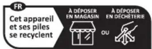
The product, its packaging and the operating instructions are recycla-
ble. They are subject to an extended manufacturer responsibility and will be collected separately.
Disposal of the device
natural_image
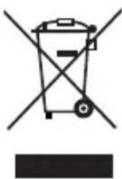
Symbol of a trash bin with crossed lines indicating no waste or discharge, and a solid black rectangle below (no text or labels)The adjacent symbol of a crossed-out wheelie bin means that this device is subject to Directive 2012/19/EU. This directive states that this device may not be disposed of in the normal
household waste at the end of its useful life, but should be handed in at specially set-up collection locations, recycling depots or disposal companies.
This disposal is free of charge for the user. Protect the environment and dispose of this device properly.
If your old device has stored any personal data, you are responsible for deleting it yourself before returning it.
If it is possible to do so without destroying the old device, remove the old batteries/rechargeable batteries as well as any lamps before returning the device for disposal and take them to a separate collection point. If the rechargeable batteries are permanently installed, you must indicate during disposal that the device contains a battery.

Your local community or municipal authorities can provide information on how to dispose of the worn-out product.
Disposal of the packaging

The packaging materials have been selected for their environmental friendliness and ease of disposal and are therefore recyclable. Dispose of packaging materials that are no longer needed in accordance with applicable local regulations.
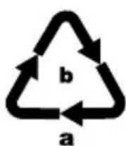
Dispose of the packaging in an environmentally friendly manner. Note the labelling on the packaging and separate the packaging material components for disposal, if necessary. The packaging material is labelled with abbreviations (a) and numbers (b) with the following meanings:
1–7: plastics, 20–22: paper and cardboard, 80–98: composites.
Applies only to Spain:
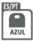
The packaging contains paper and/or cardboard components.
Disposal of batteries
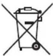
Batteries/rechargeable batteries must be treated as hazardous waste and must therefore be disposed of in an environmentally sound manner by appropriate bodies (retailers, specialist retailers, public municipal bodies, commercial disposal companies).
Batteries/rechargeable batteries may contain toxic heavy metals. The heavy metals contained are identified by letters below the symbol: Cd = cadmium, Hg = mercury, Pb = lead.
For this reason, do not dispose of batteries/rechargeable batteries in domestic waste. Take them to a specialist collection point. Only return batteries or rechargeable batteries when they are fully discharged.
Appendix
Technical data
| Operating voltage | 2× 1.5 V = alkaline batteries of type AAA/Micro/LR03 |
| LCD display | 3 % digits (max. measured values: 6000) |
| Sampling rate approx. 3 times/s | |
| Probe length approx. 94 cm | |
| Overvoltage category | CAT III 600 V |
| Jaw opening range max. 26mm | |
| Max. measurable conductor diameter | approx. ∅ 27 cm |
| IP protection type IP20 | |
Meter specifications
The following accuracy data and other specifications of the device apply for a period of one year after calibration and at a temperature of +18 to +28 °C and a relative humidity of up to 75 %.
The accuracy specifications are as follows:
■ (% of the measured value)
■ + (number of least significant digits)
Unless otherwise specified, the accuracy is between 5 and 100 % of the range. Under deviating conditions, the accuracies/specifications given below cannot be guaranteed.
DC voltage (V=)
| Measuring range | Resolution Accuracy |
| 600 mV | 0.1 mV ±(0.5 % +3) |
| 6 V | 0.001 V ±(0.8 % +5) |
| 60 V | 0.01 V ±(0.8 % +5) |
| 600 V | 0.1 V ±(0.8 % +5) |
Input impedance: approx. 10 MΩ
Overload protection: 600 V DC/AC RMS
Maximum permissible
input voltage: 600 V DC
AC voltage (V \~)
| Measuring range | Resolution Accuracy |
| 6 V | 0.001 V ± (0.8 % +5) |
| 60 V | 0.01 V ± (1.2 % +5) |
| 600 V | 0.1 V ± (1.2 % +5) |
Input impedance: approx. 10 MΩ
Overload protection: 600 V DC/AC RMS
Maximum permissible
input voltage: 600 V AC RMS
Frequency range: 40–400 Hz
Measured value: True RMS
Crest factor: 3.0
Alternating current strength (A\~)
| Measuring range | Resolution Accuracy |
| 6 A 0.001 A ± (4 % | +15) |
| 60 A 0.01 A ± (2.5 % | +10) |
| 600 A 0.1 A ± (2.5 % | +10) |
Max. permissible
input current: 600 A AC RMS
Frequency range: 50–60 Hz
Measured value: True RMS
Crest factor: 3.0
Resistance (Ω)
| Measuring range | Resolution | Accuracy |
| 600 Ω | 0.1 Ω ± (1.0 % +15) | |
| 6 kΩ | 0.001 kΩ ± (0.8 % +3) | |
| 60 kΩ | 0.01 kΩ ± (0.8 % +3) | |
| 600 kΩ | 0.1 kΩ | ± (0.8 % +3) |
| 6 MΩ | 0.001 MΩ | ± (0.8 % +3) |
| 60 MΩ | 0.01 MΩ | ± (1.0 % +25) |
Open-circuit voltage: < 0.7 V
(i) Note: When measuring the resistance of any circuit/component (especially with low resistance), the resistance of the connected test probes/cables must be taken into account in order to improve the accuracy of the measured value.
Diode test (▶+)
| Measuring range | Description Accuracy | |
 | The display5 shows the approximate forward voltage drop of the diode to be tested. | Open-circuit voltage: approx. 3.2 VTest current: approx. 1.8 mA |
Continuity test (•)
| Measuring range | Description Accuracy | |
| •••• | Resistance ≤ 30 Ω: The built-in buzzer sounds. | Open-circuit voltage: approx. 1.0 V |
| Resistance ≥ 30 to ≤ 100 Ω: The built-in buzzer may or may not sound. | ||
| Resistance ≥ 100 Ω: The built-in buzzer does not sound. |
Capacitance (+)
| Measuring range | Resolution Accuracy |
| 6 nF | 0.001 nF ± (5.0 % +10) |
| 60 nF | 0.01 nF ± (3.0 % +10) |
| 600 nF | 0.1 nF ± (3.0 % +10) |
| 6 μF | 0.001 μF ± (3.0 % +10) |
| 60 μF | 0.01 μF ± (3.0 % +10) |
| 600 μF | 0.1 μF ± (3.0 % +10) |
| 6000 μF | 1 μF ± (5.0 % +5) |
Frequency (Hz)
| Measuring range | Resolution Accuracy | |
| 6 Hz | 0.001 Hz ± (1.0 % +5) | |
| 60 Hz | 0.01 Hz ± (1.0 % +5) | |
| 600 Hz | 0.1 Hz ± (1.0 % +5) | |
| 6 kHz | 0.001 kHz ± (1.0 % +5) | |
| 60 kHz | 0.01 kHz ± (1.0 % +5) | |
| 600 kHz | 0.1 kHz ± (1.0 % +5) | |
| 1 MHz | 0.001 MHz ± (1.0 % +5) | |
| > 1 MHz | Not speci-fied | Not specified |
Required input voltage: 1–20 V RMS
(i) Note: (1) Never measure frequencies with a voltage of >20 V. Risk of damage to property. (2) The frequency of the input signal should be more than 2 Hz to avoid signal loss.
Kompernass Handels GmbH warranty Dear Customer,
This appliance has a 3-year warranty valid from the date of purchase. If included with the product on delivery, the battery packs of the X12V and X20V Team series also come with a 3-year warranty from the date of purchase. If this product has any faults, you, the buyer, have certain statutory rights. Your statutory rights are not restricted in any way by the warranty described below.
Warranty conditions
The warranty period starts on the date of purchase. Please keep your receipt in a safe place. This will be required as proof of purchase.
If any material or manufacturing fault occurs within three years of the date of purchase of the product, we will either repair or replace the product for you or refund the purchase price (at our discretion).
This warranty service requires that you present the defective appliance and the proof of purchase (receipt) within the three-year warranty period, along with a brief written description of the fault and of when it occurred.
If the defect is covered by the warranty, your product will either be repaired or replaced by us. The repair or replacement of a product does not signify the beginning of a new warranty period.
Warranty period and statutory claims for defects
The warranty period is not prolonged by repairs effected under the warranty.
This also applies to replaced and repaired components. Any damage and defects present at the time of purchase must be reported immediately after unpacking. Repairs carried out after expiry of the warranty period shall be subject to a fee.
Scope of the warranty
This appliance has been manufactured in accordance with strict quality guidelines and inspected meticulously prior to delivery.
The warranty covers material faults or production faults. The warranty does not cover product parts that are subject to normal wear and tear and can therefore be considered wearing parts, such as saw blades, replacement blades, abrasive papers, etc. or for damage to fragile parts, such as switches or parts made of glass.
The warranty does not apply if the product has been damaged, improperly used or improperly maintained. The directions in the operating instructions for the product regarding proper use of the product are to be strictly followed. Uses and actions that are discouraged in the operating instructions or which are warned against must be avoided.
This product is intended solely for private use and not for commercial purposes. The warranty shall be deemed void in cases of misuse or improper handling, use of force and modifications/repairs which have not been carried out by one of our authorised Service centres.
The warranty does not apply to
■ Normal reduction of the battery capacity over time
■ Commercial use of the product
■ Damage to or alteration of the product by the customer
■ Non-compliance with safety and maintenance instructions, operating errors
■ Damage caused by natural hazards
Warranty claim procedure
To ensure quick processing of your case, please observe the following instructions:
■ Please have the till receipt and the item number (IAN) 479089_2410 available as proof of purchase.
■ You will find the item number on the type plate on the product, an engraving on the product, on the front page of the operating instructions (below left) or on the sticker on the rear or bottom of the product.
If functional faults or other defects occur, please first contact the service department listed below by telephone or use our contact form, which you can find on parkside-diy.com in the Service category.
■ You can return a defective product to us free of charge to the service address that will be provided to you. Ensure that you enclose the proof of purchase (till receipt) and information about what the defect is and when it occurred.
text_image
PDF ONLINE parkside-diy.comYou can view and download these instructions along with many other manuals at parkside-diy.com. This QR code will take you directly to parkside-diy.com. Select your
country and use the search box to search for the operating instructions. Enter the article number (IAN) 479089_2410 to find the operating instructions for your article.
Service
GB Service Great Britain
Tel.: 0800 051 897 0
Contact form on parkside-diy.com
IE Service Ireland
Tel.: 1800 851251
Contact form on parkside-diy.com
IAN 479089_2410
Importer
Please note that the following address is not the service address. Please use the service address provided in the operating instructions.
KOMPERNASS HANDELS GMBH
BURGSTRASSE 21
44867 BOCHUM
GERMANY
www.kompernass.com
Inhaltsverzeichnis
Einführung 32
KOMPERNASS HANDELS GMBH
BURGSTRASSE 21
44867 BOCHUM
DEUTSCHLAND
www.kompernass.com
Table des matières
Introduction 67
Mesurer la tension continue (V ≠.....8 0
Mesurer la tension alternative (V) ..... 8 0
natural_image
Symbol of a trash bin with crossed lines indicating no waste or discharge (no text or labels)Tension continue (V=)
| Plage de mesure | Résolution Précision |
| 600 mV 0,1 mV ±(0,5 % +3) | |
| 6 V 0,001 V ±(0,8 % +5) | |
| 60 V 0,01 V ±(0,8 % +5) | |
| 600 V 0,1 V ±(0,8 % +5) | |
Tension alternative (V \~)
la surcharge : 600 V DC/AC RMS
Tension d'entrée
max. admissible : 600 V CA RMS
KOMPERNASS HANDELS GMBH
BURGSTRASSE 21
44867 BOCHUM
ALLEMAGNE
www.kompernass.com
Inhoud
Inleiding 107
Wisselstroom meten (A)....120
Weerstand meten (Ω....1 2 1
Diodetest (▶)....1 2 1
Doorgangstest (•) 1 2 2
Capaciteit meten (122
Frequentie meten (Hz) 123
Problemen oplossen 124
Reinigen 124
Opbergen 125
Afvoeren 125
natural_image
Symbol of a trash bin crossed with no text or numbers, representing waste sorting or disposal (no text present)KOMPERNASS HANDELS GMBH
BURGSTRASSE 21
44867 BOCHUM
DUITSLAND
www.kompernass.com
Obsah
Úvod 140
Test diod (▶)....153
natural_image
Symbol of a trash bin crossed with no text or labels, representing waste sorting or disposal (no text present)KOMPERNASS HANDELS GMBH
BURGSTRASSE 21
44867 BOCHUM
NĚMECKO
www.kompernass.com
Spis treści
Wstep 171
natural_image
Symbol of a trash bin crossed with no text or labels, accompanied by a black rectangular block below (no readable text or symbols)KOMPERNASS HANDELS GMBH
BURGSTRASSE 21
44867 BOCHUM
NIEMCY
www.kompernass.com
Obsah
Úvod 204
1 – 7: plasty, 20 – 22: papier a lepenka,
KOMPERNASS HANDELS GMBH
BURGSTRASSE 21
44867 BOCHUM
NEMECKO
www.kompernass.com
Índice
natural_image
Symbol of a trash bin crossed with a diagonal line and a horizontal bar below (no text or labels)KOMPERNASS HANDELS GMBH
BURGSTRASSE 21
44867 BOCHUM
ALEMANIA
www.kompernass.com
Indholdsfortegnelse
Introduktion 268
natural_image
Symbol of a trash bin crossed with no text or labels, representing waste sorting or disposal (no text present)KOMPERNASS HANDELS GMBH
BURGSTRASSE 21
44867 BOCHUM
TYSKLAND
www.kompernass.com
Indice
Introduzione 299
natural_image
Symbol of a trash bin crossed with no visible text or labelsKOMPERNASS HANDELS GMBH
BURGSTRASSE 21
44867 BOCHUM
GERMANIA
www.kompernass.com
Tartalomjegyzék
Bevezető 3 3 3
KOMPERNASS HANDELS GMBH
BURGSTRASSE 21
44867 BOCHUM
Németország
www.kompernass.com

text_image
PDF ONLINE parkside-diy.com
text_image
FR Creative CommonsKOMPERNASS HANDELS GMBH
BURGSTRASSE 21
44867 BOCHUM
GERMANY
www.kompernass.com