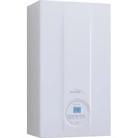
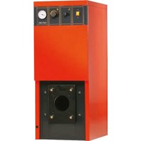
RMG Mk.II - Boiler SIME - Free user manual and instructions
Find the device manual for free RMG Mk.II SIME in PDF.


User questions about RMG Mk.II SIME
0 question about this device. Answer the ones you know or ask your own.
Ask a new question about this device
Download the instructions for your Boiler in PDF format for free! Find your manual RMG Mk.II - SIME and take your electronic device back in hand. On this page are published all the documents necessary for the use of your device. RMG Mk.II by SIME.
USER MANUAL RMG Mk.II SIME
natural_image
Exterior view of a silver industrial control unit with control panel and ventilation slots (no visible text or symbols)IT
ES
FR
ENG
PER L'INSTALLATORE
INDICE
text_image
Technical schematic diagram of an industrial control unit with numbered components and labeled partsLEGENDA
natural_image
Technical line drawing of a two-story building frame with a vertical dimension labeled 'H' (no text or symbols beyond the label)natural_image
Technical line drawing of a mechanical assembly with no visible text or symbolsFig. 3/a
text_image
Technical diagram of a mechanical assembly with numbered components for identificationLEGENDA
text_image
Technical diagram of a mechanical assembly with numbered components and directional arrows indicating motion or flow.HONEYWELL VR 420 PB
text_image
Technical diagram of a mechanical device with labeled components and directional arrows indicating flow or movement.LEGENDA
natural_image
Diagram of a hand holding a tool with a directional arrow indicating movement (no text or symbols present)LEGENDA
text_image
Technical diagram of a mechanical assembly with numbered components, likely a valve or actuator component.LEGENDA
text_image
7 10 8 * # # # # # # # # # # # # # # # # # # # # # # # # # # # # # # # # # # # # # # # # # # # # # # # # # # # # # # # # # # # # # # # # # # # # # # # # # # # # # # # # # # # # # # # # # # # # # # # # # # # # @ Figure 16text_image
Technical diagram of a device control panel with labeled buttons and indicators, including a zoomed-in view of the connector.Fig. 17
MANUTENZIONE
text_image
Technical schematic diagram of a device with numbered components and labeled partsLEYENDA
natural_image
Technical line drawing of a mechanical assembly with no visible text or symbolsIG Interruptor general
text_image
Technical diagram showing assembly steps of a mechanical device with labeled components 1, 2, 3, and 4.LEYENDA
text_image
Technical diagram of a mechanical assembly with numbered components for identificationHONEYWELL VR 420 PB
text_image
g1 3LEYENDA
natural_image
Diagram of a hand holding a mechanical device with a cylindrical component and an upward arrow (no text or symbols)LEYENDA
text_image
Technical diagram of an open refrigerator internal structure with numbered components for identificationFig. 12
text_image
Technical diagram of a heat exchanger with labeled components and assembly stepsLEYENDA
text_image
Technical diagram of a device panel with labeled buttons and indicators, including a zoomed-in view of the connector pin.Fig. 16
text_image
Technical diagram of a device control panel with labeled buttons and gauges, showing a close-up of the connector detail.Fig. 17
natural_image
Technical line drawing of a mechanical assembly with no visible text or symbolstext_image
Technical diagram of a mechanical assembly with numbered components for identificationLEGENDE
text_image
Technical diagram of a mechanical device with labeled parts and directional arrows indicating flow or movement.Fig. 10
TABLEAU 1
natural_image
Diagram of a hand operating a mechanical device with a right-hand arrow indicating upward motion (no text or symbols present)LEGENDE
text_image
Diagram of a device control panel with labeled buttons and indicators, showing a zoomed-in view of the component.Fig. 16
text_image
Diagram of a control panel with labeled buttons and indicators, showing a zoomed-in view of the button.Fig. 17
text_image
ALLUMAGE DU VOYANT ROUGE DU BOUTON DE BLOCAGEFig. 18
Our Company declares that RMG MkII boilers comply with the essential requirements of the following directives:
- Boiler Efficiency Directive 92/42/EEC
- Gas Appliances Directive 2009/142/EC
- Electromagnetic Compatibility Directive 2014/30/UE
- Low Voltage Directive 2014/35/UE
IMPORTANT
When carrying out commissioning of the boiler, you are highly recommended to perform the following checks:
- Make sure that there are no liquids or inflammable materials in the immediate vicinity of the boiler.
- Make sure that the electrical connections have been made correctly and that the earth wire is connected to a good earthing system.
- Open the gas tap and check the soundness of the connections, including that of the burner.
- Make sure that the boiler is set for operation for the type of gas supplied.
- Check that the flue pipe for the outlet of the products of the combustion is unobstructed.
- Make sure that any shutoff valves are open.
- Make sure that the system is charged with water and is thoroughly vented.
- Purge the system, bleeding off the air present in the gas pipe by operating the pressure relief valve on the gas valve inlet.
CHARACTERISTICS OF THE SYSTEM SAFETY VALVE: calibration pressure: 4 bar, maximum generator power: 205.8 Kw, 1/2" x 3/4" fixtures (see Caleffi catalogue, code 527440).
1 DESCRIPTION OF THE BOILER
1.1 INTRODUCTION
The "RMG Mk.II" are hot water generators designed for medium-sized heating
plants. These appliances can be fired by natural gas (methane) and butane gas (G30) or propane gas (G31).
The instructions given in this manual are
provided to ensure proper installation and perfect operation of the appliance.
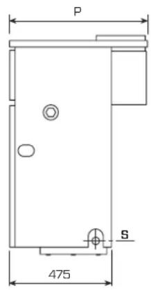
1.2 DIMENSIONS (fig. 1)
text_image
P S 475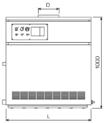
text_image
D 1000 L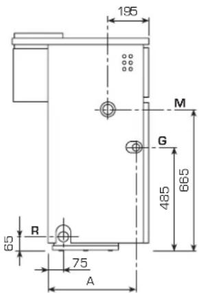
text_image
195 M G 665 485 65 R 75 A| R | C.H. return 1 | 1/2 |
| M | C.H. flow 1 | 1/2 |
| G | Gas connection 1" | |
| S | Boiler/filling drain 3/4 " |
| L | D | P | A | |
| mm | ø mm | mm | mm | |
| 70 Mk.II | 840 | 180 | 645 | 415 |
| 80 Mk.II | 940 | 180 | 645 | 415 |
| 90 Mk.II | 1040 | 200 | 645 | 415 |
| 100 Mk.II | 1140 | 225 | 645 | 415 |
| 110 Mk.II | 1240 | 250 | 670 | 400 |
Fig. 1
1.3 TECHNICAL FEATURES
| 70 Mk.II | 80 Mk.II | 90 Mk.II | 100 Mk.II | 110 Mk.II | ||
| Heat output | kW | 49.1-70.1 | 56.0-78.7 | 63.0-90.0 | 69.9-98.6 | 74.7-107.9 |
| Heat input | kW | 54.5-77.9 | 62.2-87.4 | 70.0-100.0 | 77.7-109.5 | 85.5-120.5 |
| Sections | n° | 8 | 9 | 10 | 11 | |
| Power consumption | W | 16 | 16 | 16 | 16 | 69 |
| Maximum water head | bar | 4 | 4 | 4 | 4 | 4 |
| Test pressure | bar | 6 | 6 | 6 | 6 | 6 |
| Water content | I | 25 | 28 | 31 | 34 | 37 |
| Category | II2H3+ | II2H3+ | II2H3+ | II2H3+ | II2H3+ | |
| Type | B11BS | B11BS | B11BS | B11BS | B11 | |
| Smokes temperature | °C | 158 | 160 | 160 | 144 | 140 |
| Smokes flow | kg/h | 170 | 180 | 230 | 287 | 330 |
| Maximum temperature | °C | 95 | 95 | 95 | 95 | 95 |
| C.H. setting range | °C | 40÷85 | 40÷85 | 40÷85 | 40÷85 | 40÷85 |
| Main burner nozzles | ||||||
| Quantity | n° | 7 | 8 | 9 | 10 | 11 |
| Natural gas | ø mm | 2.95 | 2.95 | 2.95 | 2.95 | 2.95 |
| G30 - G31 | ø mm | 1.70 | 1.70 | 1.70 | 1.70 | 1.70 |
| Gas consumption * | ||||||
| Natural gas | m3st/h | 8.2 | 9.2 | 10.6 | 11.6 | 12.7 |
| Butane (G30) | kg/h | 6.0 | 6.8 | 7.7 | 8.5 | 9.3 |
| Propane (G31) | kg/h | 5.9 | 6.7 | 7.6 | 8.3 | 9.1 |
| Burner gas pressure | ||||||
| Natural gas | mbar | 4.5 - 9.3 | 4.6 - 9.1 | 4.7 - 9.3 | 4.7 - 9.3 | 4.6 - 9.3 |
| Butane (G30) | mbar | 12.2 - 25.2 | 12.3 - 25.4 | 12.0 - 25.1 | 12.5 - 25.1 | 12.6 - 25.6 |
| Propane (G31) | mbar | 16.4 - 32.6 | 16.1 - 30.2 | 15.6 - 30.0 | 16.6 - 32.7 | 16.6 - 34.3 |
| Gas supply pressure | ||||||
| Natural gas | mbar | 20 | 20 | 20 | 20 | 20 |
| Butane (G30) | mbar | 30 | 30 | 30 | 30 | 30 |
| Propane (G31) | mbar | 37 | 37 | 37 | 37 | 37 |
| Weight | kg | 238 | 266 | 294 | 322 | 350 |
* The gas consumptions refer to the calorific value at standard conditions at 15°C - 1013 mbar.
1.4 MAIN COMPONENTS (fig. 2)
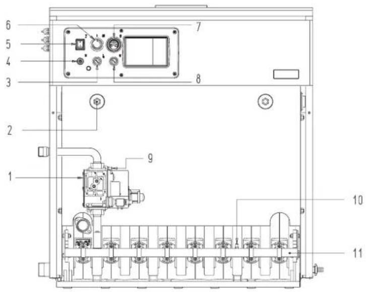
text_image
Technical schematic diagram of an industrial control unit with numbered components and labeled partsKEY
1 Gas valve with coil assembly
2 1/2" bulb holder
3 Safety stat
4 Lock out reset button
5 Main switch
6 Regulation sta with double contact
7 Thermometer
8 Smoke stat
("70 - 80 - 90 100" models)
9 1/8" pressure test point ("110" models)
10 1/8" pressure test point
11 Burner manifold
Fig. 2
2 INSTALLATION
The boiler must be installed in a fixed location and only by specialized and qualified firms in compliance with all instructions contained in this manual.
Furthermore, the installation must be in accordance with current standards and regulations.
2.1 BOILER ROOM (fig. 3)
The boilers must only be installed in boiler rooms and FULLY protected environments, installation in places such as porches or partially protected environments is not permitted.
The "RMG Mk.II" boilers with a rating of more than 35 kW must be equipped with a technical room whose dimensions and requirements correspond to the current safety standards.
The minimum height of the boiler room must comply with what is indicated in fig. 3 in relation to the overall thermal capacity.
The minimum distance between the walls of the room and the external points of the boiler (right, left side, rear) must not be less than 0.60 m.
It is possible to place a number of apparatus next to each other, on condi-
tion that all the safety and control devices can be easily reached. In addition, to circulate air in the room, air vents must be made on the outside walls for which the surface area must never be less than 3,000 cm ^2 and 5,000 cm ^2 for gas with a density greater than 0.8.
2.1.1 Handling (fig. 3/a)
Once the boiler is in its place of installation and the packaging has been removed, proceed as follows if it must be moved (fig. 3/a):
- remove the casing cover;
- attach the lifting brackets (located on the rear of the boiler) and fasten it in place with the screws provided;
- insert two 3/4" pipes in the holes in the brackets, lift the boiler carefully and place into position.
2.2 CONNECTING UP SYSTEM
Before proceeding to connect up the boiler, you are recommended to make the water circulating in the piping in
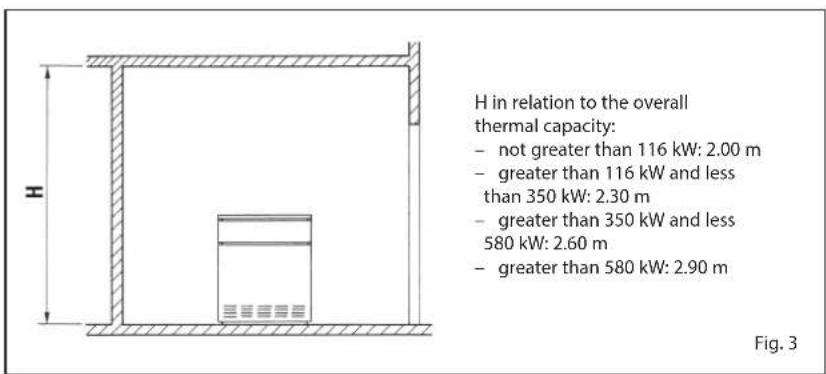
text_image
H in relation to the overall thermal capacity: - not greater than 116 kW: 2.00 m - greater than 116 kW and less than 350 kW: 2.30 m - greater than 350 kW and less 580 kW: 2.60 m - greater than 580 kW: 2.90 m Fig. 3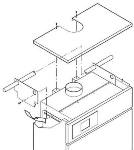
natural_image
Technical line drawing of a mechanical assembly with no visible text or symbolsFig. 3/a
order to eliminate any foreign bodies that might be detrimental to the operating efficiency of the appliance.
The unit must be connected up with rigid pipe fittings which will not subject it to stress of any kind.
The connections should be easy to disconnect using pipe unions with orientable connections. You are recommended to install suitable shutoff valves on the system flow and return pipes.
In order to achieve a good water distribution inside the cast-iron body, the system flow and return pipes should be connected to the same side of the boiler.
The boiler comes supplied standard with the attachments on the right-hand side, with the possibility of them being transferred to the left-hand side.
In that case, move the water distributor, located on the return header, and the thermostat bulbs located in the sheathe, to the same side.
The thermal jump between the system flow and return pipes should not exceed 20°C. For this purpose, it is advisable to install a mixer valve with corresponding anti-condensation pump.
CAUTION: The system circulation pump or pumps must go into action at the time of boiler ignition. For this purpose, you are recommended to use an automatic system of precedence.
The gas connection must be made using seamless steel pipe (Mannesmann type), galvanized and with threaded joints provided with gaskets, excluding three-piece connections, except for initial and end connections. Where the piping has to pass through walls, a suitable insulating sleeve must be provided.
When sizing gas piping, from the meter to the boiler, take into account both the volume flow rates (consumption) in m^3/h and the relative density of the gas in question.
The sections of the piping making up the system must be such as to guarantee a supply of gas sufficient to cover the maximum demand, limiting pressure loss between the gas meter and any apparatus being used to not greater than:
- 1.0 mbar for family II gases (natural gas);
- 2.0 mbar for family III gases (butane or propane).
An adhesive data plate is sticked inside the front panel; it contains all the technical data identifying the boiler and the type of gas for which the boiler is arranged.
2.3 CHARACTERISTICS OF FEEDWATER
It is absolutely essential that the water used for the central heating system should be treated in the following cases:
- Very extensive systems (with high contents of feedwater).
- Frequent addition of makeup water into the system.
- Should it be necessary to empty the system either partially or totally.
2.3.1 Filter on the gas pipe
The gas valve is supplied ex factory with an inlet filter, which, however, is not adequate to entrap all the impurities in the gas or in gas main pipes.
To prevent malfunctioning of the valve, or in certain cases even to cut out the safety device with which the valve is equipped, install an adequate filter on the gas pipe.
2.4 SYSTEM FILLING
Filling must be done slowly so as to allow any air bubbles to be bled off through the air vents provided on the heating system. The pressure of cold charging of the system, and the pressure of pre-presurization of the expansion vessel, must correspond, or in any case must not be less than, the height of the static column of the system (e.g., for a static column of 5 m, the pre-pressurization pressure of the expansion vessel and the charging pressure must correspond to at least 0.5 bar).
2.5 CONNECTING UP FLUE (fig. 4)
The flue for the atmospheric expulsion of the combustion products from natural draught appliances must meet the following requirements:
- Be gas-tight to the combustion products, waterproof and thermally insulated.
- Be built of materials suitable for keep resisting to normal mechanical stresses, heat, and the action of combustion products and their possible condensates.
- Follow a vertical path and not present any throttling throughout its entire length.
- Be adequately insulated to prevent phenomena of condensation or smokes cooling, in particular if located outside the building or in unheated ambiences.
- Be set at an adequate distance from combustible or easily inflammable material by means of an air gap or suitable insulating material.
- Have beneath the mouth of the first smoke duct a chamber for collecting solid material and any condensate; the height of the chamber must be at least 500 mm.
Access to the chamber must be guaranteed by means of an opening provided with an air-tight metal door.
- Have a circular, square, or rectangular internal cross section; in the case of square or rectangular sections, the corners must be rounded off with a radius of not less than 20 mm. However, hydraulically equivalent cross sections are allowed.
- Be equipped with a chimney-pot at the top, which must be outside the so-called back-flow zone, so as to prevent the formation of back-flow, which prevents free discharge of the products of combustion into the atmosphere.
Therefore, conform to the minimum heights indicated in fig. 4.
- Be devoid of mechanical means of suction located at the top of the pipe.
- No overpressure should be present in a chimney that passes within or close up to inhabited rooms.
Flat roof
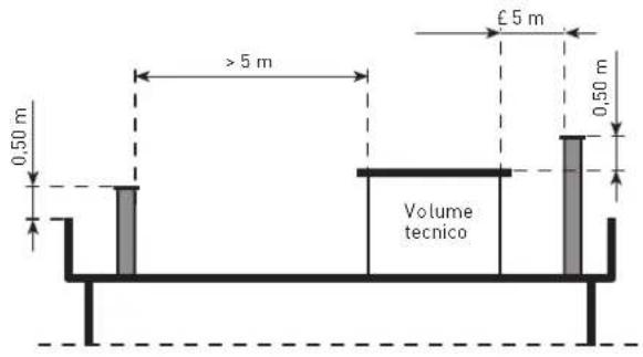
text_image
0,50 m >5 m Volume tecnico £5 m 0,50 m30° roof
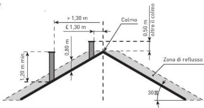
text_image
> 1,30 m £ 1,30 m Colmo 0,50 m oltre il colmo 0,80 m 1,20 m min. Zona di reflusso 30°45° roof
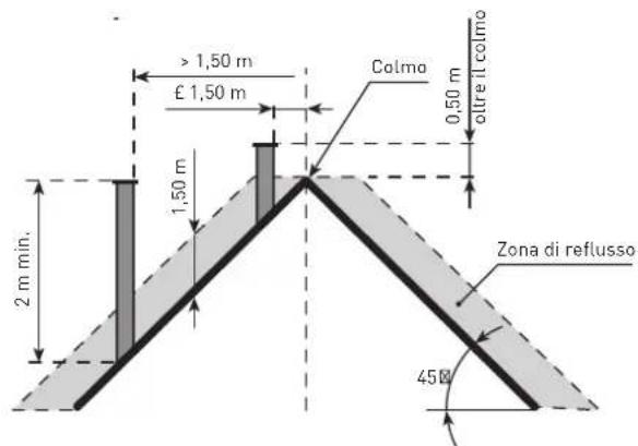
text_image
> 1,50 m £ 1,50 m Colma 0,50 m oltre il colmo 1,50 m 2 m min. Zona di reflusso 45BFig. 4
2.5.1 Sizing of flue
The correct sizing of the flue is an essential condition for efficient boiler operation.
The main factors to be taken into consideration for calculating the section are the heat input of the boiler, the type of fuel, the percentage of CO_2 , the mass flow of smoke at nominal load, the temperature of the smoke, the roughness of the internal wall, and the effect of gravity on the draught pressure, which must take into account the external temperature and the altitude.
2.6 ELECTRICAL
CONNECTION
The boiler is supplied with an electric cable. Should this require replacement, it must be purchased exclusively from SIME.
The electric power supply to the boiler must be 230V-50Hz single-phase through a fused main switch, with at least 3 mm spacing between contacts. The room stat must be class II as specified by standard EN 60730.1 (clean contact).
NOTE: Device must be connected to an efficient earthing system.
SIME declines all responsibility for injury or damage to persons, animals or things, resulting from the failure to provide for proper earthing of the appliance.
Always turn off the power supply before doing any work on the electrical panel.
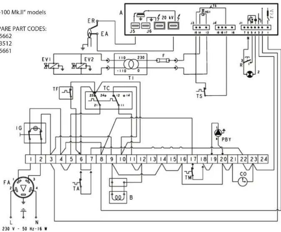
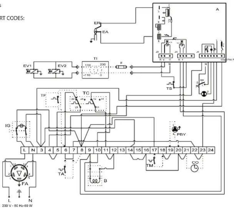
2.6.2 Wiring diagram (fig. 6)
"RMG 70-80-90-100 Mk.II" models
CONNECTOR SPARE PART CODES:
J1 code 6325662
J3 code 6293512
J4 code 6325661
text_image
100 Mk.II" models ARE PART CODES: 5662 3512 5661 EV1 EV2 110 230 -110 0 F T1 TF TC 220 240 12 14 21 11 1 2 3 4 5 6 7 8 9 10 11 12 13 14 15 16 17 18 19 20 21 22 23 24 FA L N 230 V - 50 Hz - 16 W"RMG 110 Mk.II" models
CONNECTOR SPARE PART CODES:
J1 code 6293511
J3 code 6293512
J4 code 6293510
text_image
RT CODES: EV1 EV2 TI 230 F TS TP TC IG L N 3 4 5 6 7 8 9 10 11 12 13 14 15 16 17 18 19 20 21 22 23 24 TA B L N FA L A J1 J2 J3 J4 J5 J6 J7 J8 R PBY TM CO 230 V - 50 Hz-69 WKEY
IG Main switch
TC Regulation stat with
double contact
EA Ignition electrode
EV2 Gas valve coil
EV1 Gas valve coil
TA Room stat
R Lock out reset button
B Coil assembly
ER Sensing electrode
TS Safety stat
A Control box
TF Smoke stat
FA EMC filter
F Fuse (T 200mA)
PBY By-pass pump
TI Isolated transformer
(only for FR/BE)
TM Minimum temperature stat
CO Hour counter
NOTE: When connecting the TA remove
the jumper from terminals 6-7.
Fig. 6
3 CHARACTERISTICS
3.1 CONTROL BOX (fig. 8)
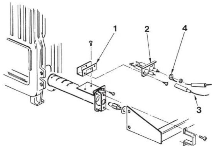
The "RMG Mk.II" boilers are provided with automatic ignition (without pilot burner). They are therefore equipped electronic control and protection, with a built-in transformer, located inside the instrument panel protection box. Ignition and flame detection is controlled by two electrodes located on the burner.
These guarantee maximum safety with intervention times, for accidental switching off or gas failure, within 8 and 4 seconds (fig. 8).
3.1.1 Operating cycle
Before igniting the boiler, use a voltmeter to make sure that the electrical connection to the terminal block has been made properly, respecting the position of live and neutral, as shown in the diagram. Then press the switch on the control panel detecting voltage and lighting the led lamp.
The boiler is now ready to start working; a discharge current is sent to the ignition electrode through the programmer, and the gas valve opens at the same time.
Burner ignition normally takes place within 2 or 3 seconds. However, it is possible for ignition failures to occur, with consequent activation of signal indicating that the equipment has "locked out".
Failures may be due to one of the following causes:
- Gas failure
The control box runs through the cycle normally sending electric power to the ignition electrode. The electrode continues spark discharge for a maximum of 8 and 4 sec. If the burner does not ignite, the control box "locks out".
This may occur upon first ignition or after long periods of boiler lay-off when there is air in the pipes. It may be caused by the failure of the gas valve to open owing to a break in the electric coil.
- Ignition electrode fails to spark
In the boiler, only opening of gas to the burner is seen to occur. After 8 and 4 sec. the control cox "locks out".
This may be due to there being a break in the wire of the electrode or the wire not being properly fastened to the terminal of the control box; or else, the transformer has burnt out.
- No detection of flame
The continuous spark discharge of the electrode is noted starting from ignition even though the burner is lit.
After 8 and 4 seconds have elapsed, the sparks cease, the burner goes out, and the warning lamp indicating equipment "lock-out" lights up.
This occurs when the position of live and neutral has not been respected on the terminal block. There is a break in the wire of the sensing electrode or the electrode itself is earthed: the electrode is worn out and needs replacing.
The control box is falty
When there is a sudden voltage failure, the burner shuts out immediately; when power supply returns, the boiler will start up again automatically.
3.1.2 Ionization circuit
The ionization circuit is to be checked using a dial-type micro-ammeter, or preferably a digital micro-ammeter with
text_image
Technical diagram of a mechanical assembly with numbered components, likely for assembly or maintenance instructions.KEY
1 Electrode support
2 Electrode unit
3 Electrode ignition cable
4 Electrode detection cable
Fig. 8
a 0 to 50 μA scale. The micro-ammeter terminals must be series-connected to the wire of the sensing electrode. Under normal operating conditions, the value oscillates between 6 - 10 μA. The minimum value of the ionization current for which the equipment can "lock out" is about 1 μA.
In this case, make sure that there is a good electrical contact and check the degree of wear of the end part of the electrode and the corresponding ceramic protection.
3.2 REGULATION THERMOSTAT
"RMG Mk.II" boilers are equipped with a regulating thermostat with a double contact having differentiated setting (6 fig. 2).
This makes it possible to obtain a reduction of heat output before the burner goes out completely, by means of the coil assembly installed on the gas valve regulator.
This step-modulation system affords the following advantages:
– higher overall boiler efficiency;
- containment within acceptable values of the increase in temperature that takes place in the cast-iron body (heat inertia) when the burner goes out.
3.3 SMOKE SAFETY DEVICE
"70 - 80 - 90 - 100 Mk.II"
MODELS
This is a safety device against possible smoke emission into the ambience (8 fig. 2).
The safety device goes into action by blocking operation of the gas valve when the return of the smoke into the ambience is continuous and in quantities that might constitute a danger.
To restart the boiler, the cover of the thermostat must be unscrewed and reset the underlying button.
Make sure the control panel is disconnected before carrying out this operation. Should the boiler continue to "lock out", it will be necessary to make a careful check on the flue pipe, making all the necessary modifications and amendments so that it can work properly.
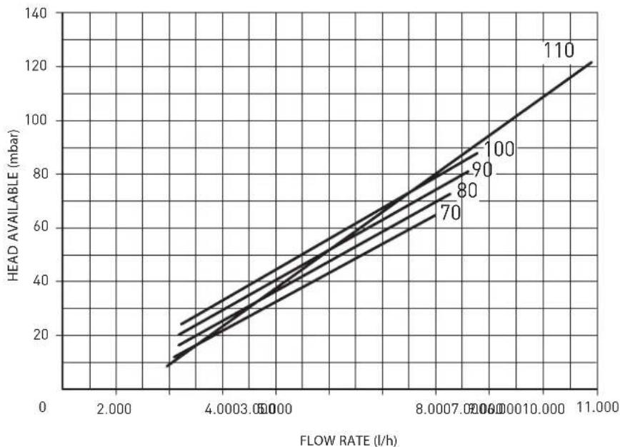
3.5 SYSTEM AVAILABLE
HEAD (fig. 9)
The head available is shown in graph in fig. 9.
line
| FLOW RATE (l/h) | HEAD AVAILABLE (mbar) | | --------------- | --------------------- | | 2.000 | 10 | | 4.0003 | 30 | | 6.0007 | 50 | | 8.0007 | 70 | | 10.000 | 90 | | 11.000 | 110 |Fig. 9
4 USE AND MAINTENANCE
4.1 GAS VALVE (fig. 10)
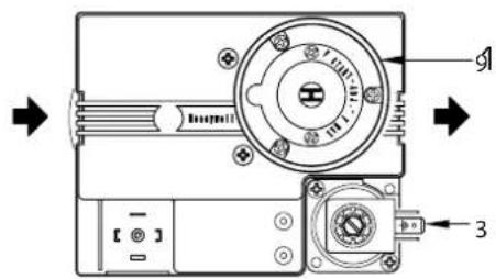
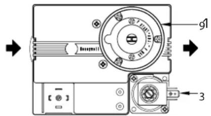
"RMG Mk.II" boilers come equipped standard with a HONEYWELL VR 4605 C gas valve (for "70 - 80" models), VR 4605 CB gas valve (for "90 - 100" models) and VR 420 PB gas valve (for "110" models).
When the boiler is ignited the first time, it is always recommended to bleed the piping by using the pressure outlet upstream from the valve (7 fig. 10 - 9 fig. 2).
4.2 GAS VALVE ADJUSTMENT
Calibration of the operating pressures is done by SIME in the factory. Consequently they should not be altered. Only when you switch to another type of gas (butane or propane) is it permitted to alter the operating pressures.
It is essential that this operation be carried out exclusively by authorized technical staff.
When the working pressures have been adjusted, reseal the regulators.
When the gas pressures are to be reset, this must be done following a set order: first the maximum pressure and then the minimum.
4.2.1 Nominal pressure
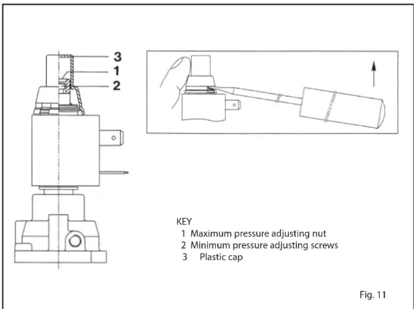
adjustment (fig. 11)
Connect the manometer to the pressure test point located on the burner manifold, turn boiler ON, and wait until a steady reading on the manometer is obtained. Compare this reading with that shown in Table 1. If any correction is required, use an 8mm spanner on the high pressure adjuster (1) turning clockwise to increase, counter-clockwise to decrease the pressure.
4.2.2 Reduced pressure adjustment (fig. 11)
Turn the boiler OFF, and remove the plug from the High - Low Coil. Turn the boiler ON and wait until a steady reading on the manometer is obtained. Compare this reading with that shown in Table 1.
If any correction is required, use a 3.5 mm flat blade screwdriver to rotate the low adjust screw (2), turning clockwise to increase and counter-clockwise to decrease the pressure. When all adjustments are completed, replace the plug on the coil, and the cap over the adjustment screws.
4.4 GAS CONVERSION
To convert to butane gas (G30) or propane gas (G31), the main nozzles must be replaced with another supplied in the boi-
HONEYWELL VR 4605 C - VR 4605 CB

text_image
Technical diagram of a mechanical assembly with numbered components for identificationKEY
1 EV1 coil
3 Pressure
regulator 3...20 mbar
4 EV2 coil
5 LPG adaptor
6 Plastic cap
7 Pressure inlet upstream
8 Pressure inlet
downstream
9 EV1-EV2 coil
HONEYWELL VR 420 PB
text_image
Technical diagram of a mechanical device with labeled parts and directional arrows indicating flow or movement.Fig. 10
TABLE 1
70 Mk.II 80 Mk.II 90 Mk.II 100 Mk.II 110 Mk.II
| Methane - G20 | ||||||
| Burner max. pressure | mbar | 9.3 | 9.1 | 9.3 | 9.3 | 9.3 |
| Burner min. pressure | mbar | 4.5 | 4.6 | 4.7 | 4.7 | 4.6 |
| Butane - G30 | ||||||
| Burner max. pressure | mbar | 25.2 | 25.4 | 25.1 | 25.1 | 25.6 |
| Burner min. pressure | mbar | 12.2 | 12.3 | 12.0 | 12.5 | 12.6 |
| Propane - G31 | ||||||
| Burner max. pressure | mbar | 32.6 | 30.2 | 30.0 | 32.7 | 34.3 |
| Burner min. pressure | mbar | 16.4 | 16.1 | 15.6 | 16.6 | 16.6 |
ler gas conversion kit, pressure regulator (3...20 mbar) with pressure regulator (4...37 mbar) and apply the LPG adaptor code 6248303 onto the gas valve (5 fig. 10) for "70÷100 Mk.II" models.
To adjust the operating pressures, refer to section 4.2.
When the working pressures have been adjusted, reseal the regulators.
After have ultimately the conversion of the boiler, please stick onto the casing panel the plate showing the relevant feeding gas which is included into the conversion kit.
NOTE: After assembling all the gas connections, a test for gas tightness must be carried out using soapy water or special products. Do not use naked flames. The conversion to different gas must be carried out exclusively by authorized technical personnel.
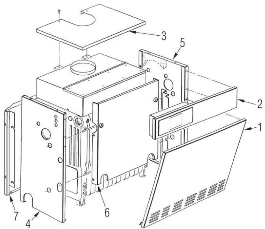
4.5 SHELL DISASSEMBLY (fig. 12)
Follow the steps described below to disassemble the shell (fig. 12):
- Remove the shell door (1) which is attached with pressure fit pins.
- To remove the cover (3) loosen the two screws that attach it to the flue gas chamber and lift.
- Remove the top front panel (2) placing it against the flue gas chamber.
- Disassemble the left side (4) unscrewing the nuts that attach it to the tie rods.
- Do the same operation to disassemble the right side (5).
- Remove the inner wall (6) by pulling it forward.
- Unscrew the nuts that secure the rear wall (7) to remove it from the tie rods.
4.6 CLEANING AND MAINTENANCE (fig. 13)
At the end of each heating season, it is essential to have the boiler thoroughly checked and cleaned out.
Proceed as follows:
- Turn the main switch off to stop electric power reaching the boiler and close the gas feed cock.
- Remove the shell door and cover.
-
Remove the top panel of the flue gas chamber attached to it with self-threading screws.
-
Remove the gas unit.
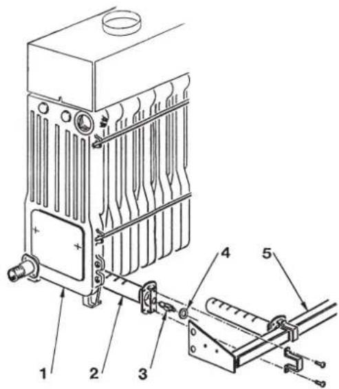
- Insert a special brush from the top into the rows of pins in the cast iron exchanger and move the brush up and down to remove the scales.
- Remove the burner from the nozzle header and aim a jet of air toward the inside of the burners to remove any dust. Make sure that there are no scales on the top drilled part of the burners (fig. 13).
- Remove any scales from the bottom of the boiler and replace the items that were removed, checking the position of the gaskets.
- Check the chimney to make sure that the flue is clean.
- Check operation of the equipment and the main burner.
- After assembly of all the gas connections, these must be tested for soundness, using soapy water or appropriate products. DO NOT USE NAKED FLAMES.
Preventive maintenance and checking of efficient operation of equipment and safety devices must be carried out exclusively by authorized technical personnel.
text_image
Technical diagram of an open refrigerator internal structure with numbered components for identificationFig. 12
4.7 FAULT FINDING
The main burner does not ignite.
- This means that the flue smoke stat has tripped off (point 3.3).
- Make sure power arrives to the gas valve.
- Replace the electric operator of the valve.
- Replace the valve.
The boiler reaches the set temperature, but the radiators do not heat up.
- Make sure there are no air bubbles in the system, if so purge from appropriate air vents.
- The room stat is too low or must be replaced if faulty.
- The connections of the room stat are not correct (make sure the cables are placed on terminals 6 and 7 of the boi-
ler terminal board).
Boiler operates only at nominal pressure and does not reduce pressure.
- Check whether there is voltage at both ends of coil.
- The coil has a break in the winding; replace.
- The rectifier card that supplies the coil is interrupted; replace.
- There is no differential on setting of the two contacts of the regulating thermostat; replace.
- Check calibration of reduced pressure adjusting screw of coil assembly.
The boiler gets dirty easily causing scaling of cast iron exchanger and cutting off of smoke stat.
- Check that the flame of the main burner is well regulated and that gas
consumption is proportional to boiler output.
- Poor ventilation of premises where boiler is installed.
- Flue with insufficient draught or not meeting requirements.
- The boiler works at too low temperatures. Adjust the boiler thermostat to higher temperatures.
Thermostat switches boiler back on with too high temperature difference.
- Replace regulating thermostat since it is out of calibration.
text_image
Technical diagram of a heat exchanger with labeled components including ports, cooling unit, and lever mechanismKEY
1 Boiler body
2 Burner
3 Main nozzle
4 Aluminium washer
5 Burner manifold
Fig. 13
ATTENTION: Before performing any work on the boiler, make sure that the same and its components have cooled in order to prevent the risk of burns due to high temperatures.
WARNINGS
- In case of fault and/or incorrect equipment operation, deactivate it, without making any repairs or taking any direct action. Contact the nearest Authorised Technical Service Centre.
- The installation of the boiler and any servicing or maintenance job must be carried out by qualified personnel. Under no circumstances, the devices sealed by the manufacturer can be tampered with.
- It is absolutely prohibited to block the intake grilles and the aeration opening of the room where the equipment is installed.
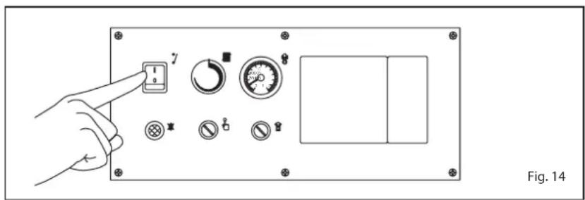
Open the gas valve and press the main switch to ignite the "RMG Mk.II" boiler (fig. 14).
TEMPERATURE ADJUSTMENT (fig. 15)
The heating temperature can be adjusted by turning the knob of the thermostat, which has a range of between 40^ C and 85^ C. The temperature setting can be checked on the thermometer.
To ensure optimal boiler efficiency at all times, we recommend not to drop below a minimum working temperature of 60^ C. In this way, any formation of condensate that might cause deterioration of the cast-iron body over time will be avoided (fig. 15).
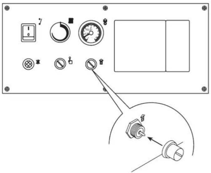
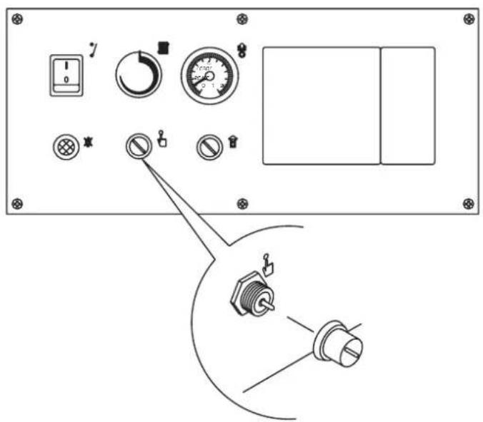
SAFETY THERMOSTAT (fig. 16)
The safety thermostat is of the manually resetting type and opens, causing the main burner to turn off immediately, whenever the temperature of 95^ C is exceeded in the boiler. To restore boiler operation, unscrew the black cap and reset the button (fig. 16).
Should the appliance again "lock out",
text_image
7 Fig. 14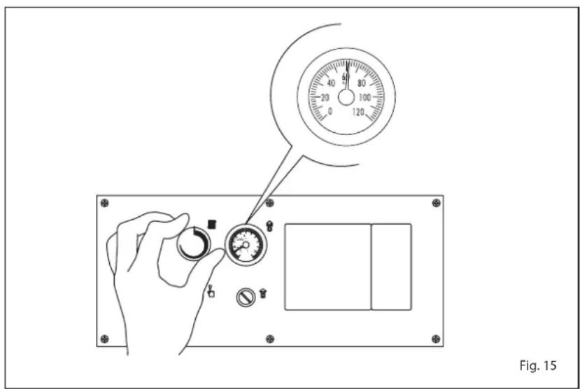
text_image
Fig. 15please approach the authorized technical staff.
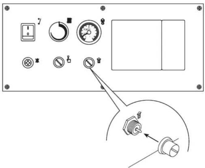
SMOKE SAFETY DEVICE
"70 - 80 - 90 - 100 Mk.II" MODELS
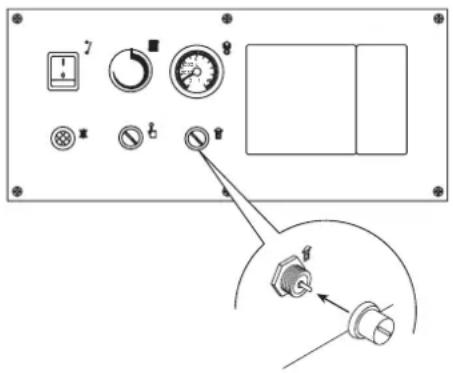
(fig. 17)
This is a safety device against possible
smoke emission into the ambience.
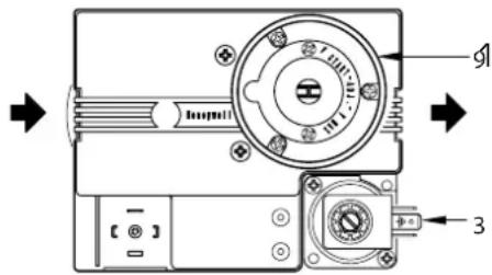
The safety device switches off the gas valve when the return of the smokes into the ambience is continuous and then dangerous. To restart the boiler, the cover of the thermostat must be unscrewed and then press the underlying button (fig. 17).
Should the boiler "lock out" again, you
must call the authorized technical staff.
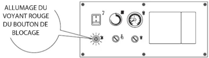
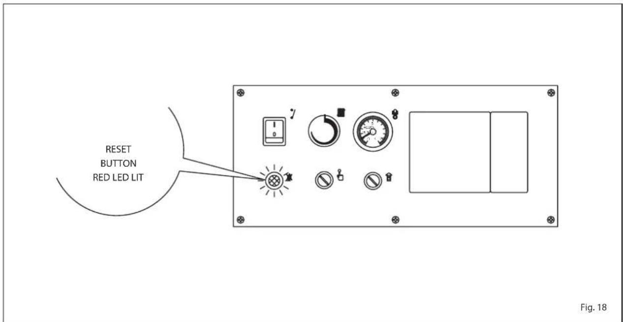
LOCK OUT RESET OF
THE CONTROL BOX (fig. 18)
If the burner does not ignite, the red led on the reset button will turn on. Press the button to restart the boiler automatically
text_image
Technical diagram of a device control panel with labeled buttons, gauges, and connectorsFig. 16
text_image
Technical diagram of a device control panel with labeled buttons and indicators, including a zoomed-in detail view.Fig. 17
(fig. 18).
Should the boiler "lock out" again, you must call the authorized technical staff.
TURNING OFF BOILER
To turn off the "RMG Mk.II" boiler completely, cut off electricity supply to the equipment by operating the main switch (fig. 14).
If the boiler is not going to be used for a lengthy period it is advised to turn off the electricity supply, close the gas cock, and if low temperatures are foreseen, empty the boiler and the hydraulic system to avoid breakage in the tubes due to the freezing of the water.
GAS CONVERSION
Should it be necessary to convert the appliance to a different gas from the one for which the boiler has been equipped, approach the technical staff.
CLEANING AND MAINTENANCE
At the end of each heating season, it is essential to have the boiler thoroughly checked and cleaned out.
Preventive maintenance and checking of the efficient operation of the equipment and safety devices must be carried out exclusively by the authorized technical staff.
ATTENTION: Before performing any work on the boiler, make sure that the same and its components have cooled in order to prevent the risk of burns due to high temperatures.
DISPOSAL OF THE EQUIPMENT
Once it reaches the end of its operating
life, the equipment MUST BE RECYCLED in line with current legislation.
IT MUST NOT be disposed of together with urban waste.
It can be handed over to recycling centres, if there are any, or to retailers that offer this service.
Recycling prevents potential damage to the environment and health. It allows to recover a number of recyclable materials, with considerable savings in terms of money and energy.
text_image
RESET BUTTON RED LED LIT Fig. 18sime
Fonderie Sime S.p.A - Via Garbo, 27 - 37045 Legnago (Vr)
Tel. +39 0442 631111 - Fax +39 0442 631292 - www.sime.it