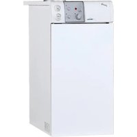
RX - Boiler SIME - Free user manual and instructions
Find the device manual for free RX SIME in PDF.


| Product type | Natural draft gas boiler |
| Available models | RX 19, RX 26, RX 37, RX 48, RX 55 (PVA versions with pump and expansion vessel) |
| Useful power | 22.0 to 60.7 kW depending on model |
| Heat input | 25.0 to 69.2 kW |
| Power supply | 230 V - 50 Hz, single phase |
| Gas supply | Natural gas (G20), butane (G30) or propane (G31) |
| Gas supply pressure | 20 mbar for G20, 30 mbar for G30, 37 mbar for G31 |
| Maximum working pressure | 4 bar |
| Maximum operating temperature | 95 °C |
| Water content | 10 to 22 litres depending on model |
| Dimensions (models 37-55) | Width (P): 670-870 mm; Height (H): 1435-1675 mm; Depth (Z): 245-345 mm; Duct diameter (D): 180-200 mm |
| Weight | 101-202 kg depending on model and version |
| Ignition | Electronic flame ionization (without pilot light) |
| Main functions | Central heating; domestic hot water production via coil heat exchanger (optional) |
| Safety devices | Safety aquastat (max temperature), flue thermostat (anti-backflow), flame detection electrode |
| Circulator (PVA models) | EURAMO NYL 40/25 or GRUNDFOS UPS 25/50, adjustable 3 speeds |
| Expansion vessel (PVA models) | 8-10 litres, pre-charge pressure 1 bar |
| Maintenance and cleaning | Mandatory cleaning after each heating season; disassemble the jacket, clean the heat exchanger and burners |
| Spare parts and repairability | Electrodes, gas valve, circulator, aquastat, flue thermostat, nozzles |
| Electrical protection rating | IPX2D |
| NOx class | 2 |
Frequently Asked Questions - RX SIME
User questions about RX SIME
0 question about this device. Answer the ones you know or ask your own.
Ask a new question about this device
Download the instructions for your Boiler in PDF format for free! Find your manual RX - SIME and take your electronic device back in hand. On this page are published all the documents necessary for the use of your device. RX by SIME.
USER MANUAL RX SIME
natural_image
Exterior view of a white industrial appliance with control panel and side-mounted buttons (no visible text or symbols)IT
RUS
ES
RO
ENG
FR
INDICE
natural_image
Technical line drawing of a mechanical assembly with dimension H, showing a central component and surrounding frame (no text or symbols)line
| Q (m³/h) | H (m) | | -------- | ----- | | 0.5 | 5.0 | | 1.0 | 4.0 | | 1.5 | 3.0 | | 2.0 | 2.0 | | 2.5 | 1.0 | | 3.0 | 0.5 | | 3.5 | 0.2 | | 4.0 | 0.1 |natural_image
Technical line drawing of a mechanical component with dimension lines and a small inset detail (no text or symbols)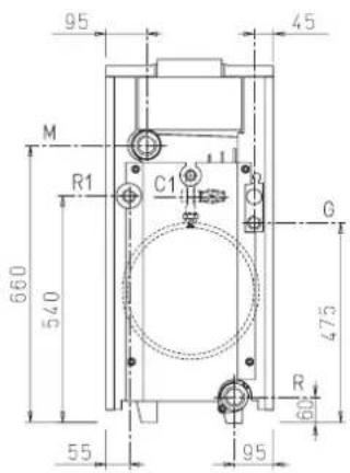
1 1/4"
1/2"
3/4"
1/2"
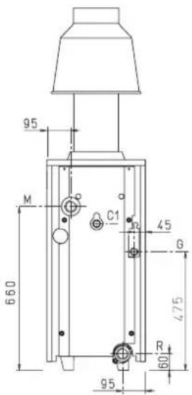
| 37 | 48 | 55 | ||
| P | mm | 670 | 770 | 870 |
| H | mm | 1435 | 1435 | 1675 |
| Z | mm | 245 | 295 | 345 |
| D | mm | 180 | 180 | 200 |
Fig. 1/a
1.3 DATOS TECNICOS
IG Interruptor general
line
| Q (m³/h) | H (m) | | -------- | ----- | | 0.5 | 5.0 | | 1.0 | 3.8 | | 1.5 | 3.0 | | 2.0 | 2.2 | | 2.5 | 1.5 | | 3.0 | 1.0 | | 3.5 | 0.5 | | 4.0 | 0.0 |1 Interruptor general
natural_image
Technical illustration of two mechanical components with a downward arrow indicating motion (no text or symbols)natural_image
Technical line drawing of a mechanical setup with a central component and dimension lines (no text or symbols)P Pompe installation
line
| Q (m³/h) | H (m) | | -------- | ----- | | 0 | 5 | | 1 | 4 | | 2 | 3 | | 3 | 2 | | 4 | 1 |4 UTILISATION ET ENTRETIEN
4.1 RÉGULATION SOUPAPE GAZ VERSION "RX19-26"
Our Company declares that RX boilers comply with the essential requirements of the following directives:
- Boiler Efficiency Directive 92/42/EEC
- Gas Appliances Directive 2009/142/EC
- Electromagnetic Compatibility Directive 2014/30/UE
- Low Voltage Directive 2014/35/UE
IMPORTANT
1 DESCRIPTION OF THE BOILER
1.1 INTRODUCTION
The new series of "RX" gas-fired heating boilers has been designed and manufactured to ensure maximum user-friendliness and to ease both the installation and the maintenance operations for the installer. These appliances can be fired by natural gas (methane) and butane gas (G30) or propane gas (G31).
This manual contains the instructions for the following boiler models:
- "RX 19÷55 CE IONO" with electronic ignition and flame ionization
- "RX 19-26 PVA CE IONO" with pump, expansion vessel, electronic ignition and flame ionization.
The instructions given in this manual are provided to ensure proper installation and perfect operation of the appliance.
1.2DIMENSIONS
1.2.1 "RX 19-26" versions
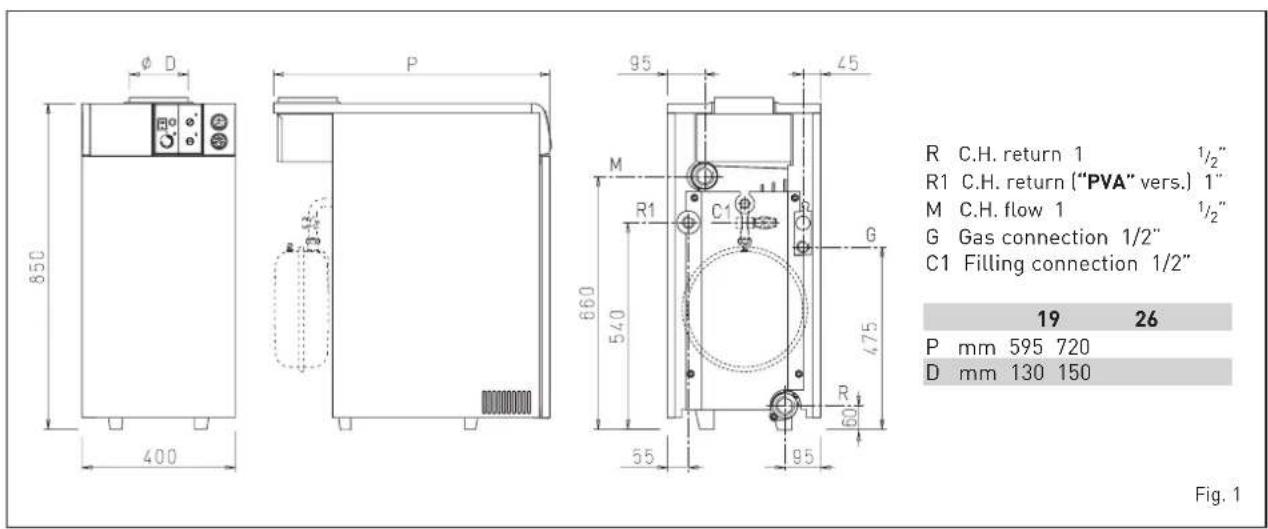
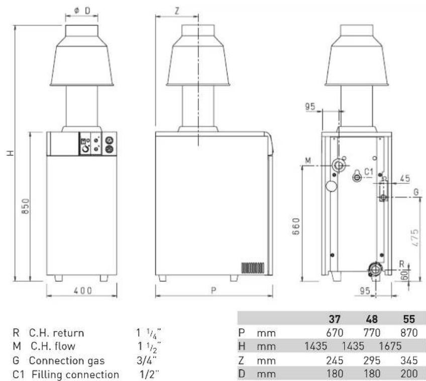
R C.H. return
M C.H. flow
G Connection gas
C1 Filling connection
1 1/4"
1 1/2
3/4"
1/2"
| 37 | 48 | 55 | ||
| P | mm | 670 | 770 | 870 |
| H | mm | 1435 | 1435 | 1675 |
| Z | mm | 245 | 295 | 345 |
| D | mm | 180 | 180 | 200 |
Fig. 1/a
1.3 TECHNICAL FEATURES
| 19 | 26 | 37 | 48 | 55 | |||
| Heat output kW | 22,0 | 30,5 | 39,1 | 48,8 | 60,7 | ||
| kcal/h | 18.900 | 26.200 | 33.600 | 42.000 | 52.200 | ||
| Heat input kW | 25,0 | 34,8 | 44,8 | 55,0 | 69,2 | ||
| kcal/h | 21.500 | 29.900 | 38.500 | 47.300 | 59.500 | ||
| IP electrical protection rating | IPX2D | IPX2D | IPX2D | IPX2D | IPX2D | ||
| NOx class | 2 | 2 | 2 | 2 | 2 | ||
| Number of sections 3 | 4 | 5 | 6 | 7 | |||
| Water content l | 10 | 13 | 16 | 19 | 22 | ||
| Power consumption | W | 2-93* | 2-93* | 16 | 16 | ||
| Maximum water head | bar | 4 | 4 | 4 | 4 | ||
| Maximum temperature | °C | 95 | 95 | 95 | 95 | ||
| Expansion vessel | |||||||
| Water content/Preloading pressure | l/bar | 8/1 | 10/1 | - | - | - | |
| Smokes temperature | °C | 119 | 118 | 110 | 130 | ||
| Smokes flow | gr/s | 24,7 | 34,7 | 52,2 | 53,1 | ||
| Category | II2H3+ | II2H3+ | II2H3+ | II2H3+ | |||
| Type *** | B11BS | B11BS | B11BS | B11BS | |||
| Weight | kg | 101-113* | 126-138* | 150 | 176 | ||
| Main burner nozzles | |||||||
| Quantity | n° | 2 | 2 | 3 | 3 | ||
| Methane/G30 - G31 | ø mm | 3,15/1,80 | 3,65/2,10 | 3,40/1,95 | 3,90/2,20 | ||
| Gas consumption ** | |||||||
| Methane | m3/h | 2,64 | 3,68 | 4,73 | 5,82 | ||
| Butane (G30)/Propane (G31) | kg/h | 1,97/1,94 | 2,74/2,69 | 3,53/3,47 | 4,34/4,27 | ||
| Burner gas pressure | |||||||
| Methane | mbar | 9,8 | 9,6 | 9,6 | 9,1 | ||
| Butane (G30)/Propane (G31) | mbar | 28/35 | 28/35 | 28/35 | 28/35 | ||
| Gas supply pressure | |||||||
| Methane | mbar | 20 | 20 | 20 | 20 | ||
| Butane (G30)/Propane (G31) | mbar | 30/37 | 30/37 | 30/37 | 30/37 | ||
* "PVA" vers.
** The gas consumptions refer to the calorific value at standard conditions at 15°C - 1013 mbar
*** For models 19-26-37-48 smoke extractor at the request type B14P-B44P. The system is optional and assembly instructions are included in the kit.
1.4 MAIN COMPONENTS
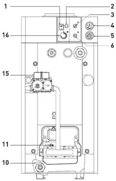
KEY
1 Main switch
2 Lock out lamp
3 Smoke stat
4 Hydrometer
5 Thermometer
6 Safety stat
10 Drain cock (1/2")
11Detectionelectrode
15Gasvalve
16 Boiler stat
Fig. 2
1.5 BOILER CIRCUIT LOAD LOSS
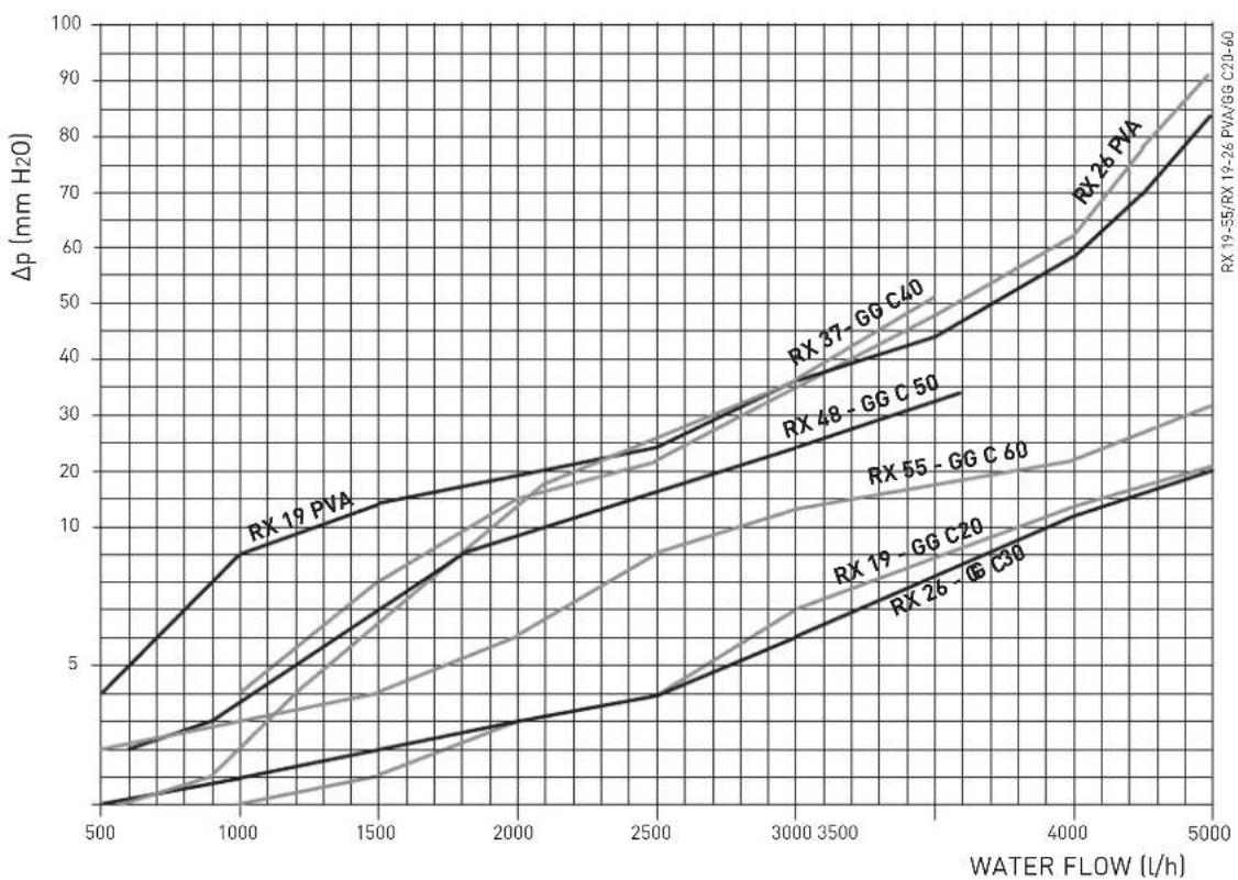
line
| WATER FLOW (l/h) | RX 19 PVA | RX 26 PVA | RX 37 - GG C40 | RX 48 - GG C50 | RX 55 - GG C60 | RX 19 - GG C20 | RX 26 - G C30 | | ---------------- | --------- | --------- | -------------- | -------------- | -------------- | -------------- | ------------- | | 500 | 4 | 4 | 4 | 4 | 4 | 4 | 4 | | 1000 | 8 | 8 | 8 | 8 | 8 | 8 | 8 | | 1500 | 12 | 12 | 12 | 12 | 12 | 12 | 12 | | 2000 | 16 | 16 | 16 | 16 | 16 | 16 | 16 | | 2500 | 20 | 20 | 20 | 20 | 20 | 20 | 20 | | 3000 | 24 | 24 | 24 | 24 | 24 | 24 | 24 | | 3500 | 28 | 28 | 28 | 28 | 28 | 28 | 28 | | 4000 | 32 | 32 | 32 | 32 | 32 | 32 | 32 | | 4500 | 36 | 36 | 36 | 36 | 36 | 36 | 36 | | 5000 | 40 | 40 | 40 | 40 | 40 | 40 | 40 |Fig. 2/a
2 INSTALLATION
The boiler should be installed in a fixed location and shall be carried out only by specialized and qualified firms in compliance with all instructions contained in this manual.
2.1 BOILER ROOM AND VENTILATION
The boilers must only be installed in boiler rooms and FULLY protected environments, installation in places such as porches or partially protected environments is not permitted.
There are no particular regulations to follow with reference to the boiler room because "RX 19-26" boilers, which do not exceed the 35 kW limit, can be installed in rooms that are sufficiently ventilated.
The rooms where the gas-fired systems are installed must receive at least the quantity of air necessary for the normal combustion of the gas used by the various installations.
Therefore, to ensure the air circulation in the rooms, it is necessary to
make some holes in the walls.
These holes must have the following characteristics:
- Have e total free surface of minimum 6 cm ^2 for each kW of thermal capacity, for a minimum of 100 cm ^2 .
- They must be located as close as possible to floor level, not prone to obstruction and protected by a grid which does not reduce the effective section required for the passage of air.
The "RX 37÷55" models with a capacity exceeding 35 kW shall instead be installed in a boiler room that meets the existing safety regulations for network gas-fired heating systems, where minimum distances must be observed.
2.2 BOILER CONNECTION
To protect the heat system from damaging corrosion, incrustation or deposits, after installation it is extremely important to clean the system using suitable products such as, for example, Sentinel X300 or X400. Complete instructions are provided with the products but, for further information, you may directly contact GE Betz.
For long-term protection agains corrosion and deposits, the use of inhibitors such as Sentinel X100 is recommended after cleaning the system. It is important to check the concentration of the inhibitor after each system modification and during maintenance following the manufacturer's instructions (specific tests are available at your dealer). The safety valve drain must be connected to a collection funnel to collect any discharge during interventions.
WARNING: Failure to clean the heat system or add an adequate inhibitor invalidates the device's warranty.
Gas connections must be made in accordance with current standards and regulations. When dimensioning gas pipes from the meter to the module, both capacity volume (consumption) in m^3/h and gas density
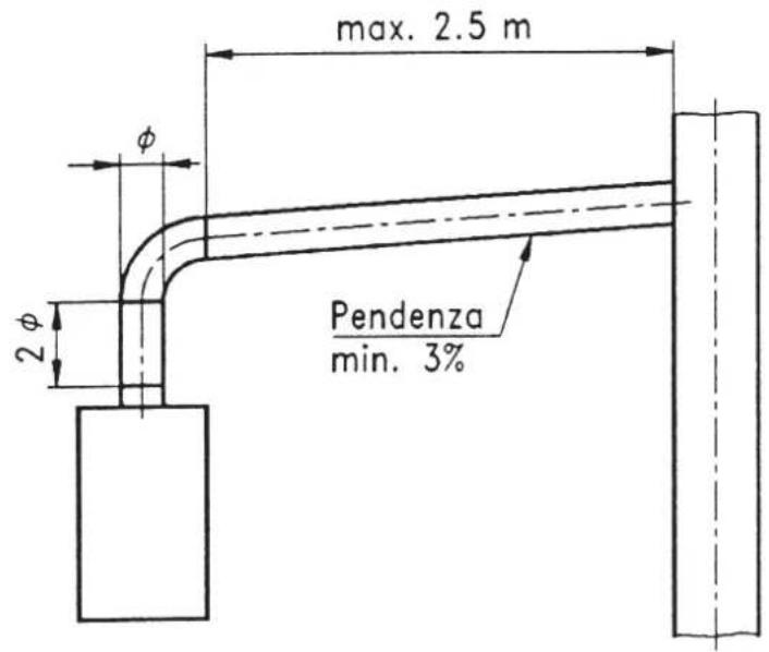
Fig. 3
must be taken into account.
The sections of the piping making up the system must be such as to guarantee a supply of gas sufficient to cover the maximum demand, limiting pressure loss between the gas meter and any apparatus being used to not greater than:
- 1.0 mbar for family II gases (natural gas);
- 2.0 mbar for family III gases (butane or propane).
A sticker inside the module includes identification and gas type data specific to the module.
2.2.1 Filter on the gas pipe
The gas valve is supplied ex factory with an inlet filter, which, however, is not adequate to entrap all the impurities in the gas or in gas main pipes.
To prevent malfunctioning of the valve, or in certain cases even to cut out the safety device with which the valve is equipped, install an adequate filter on the gas pipe.
2.4 SYSTEM FILLING
WARNING: hole C/C1 (fig. 1) is factory-supplied open.
Before filling the system, satisfy at least one of these conditions, therefore ensure at least that:
- hole C/C1 is plugged and the hydraulic seal is ensured
- the system loading pipe is connected to hole C/C1
- the safety valve is connected to hole C/C1
NOTE: Failure to install the safety devices (safety valve and expansion vessel) during the first start-up will automatically void the appliance warranty.
The filling shall be made slowly so that air bubbles are eliminated through the vents. The charge pressure, with the system cold, must between 1 and 1,2 bar. The system loading pipe can be connected with the 1/2" coupling on the back header or, on the "PVA" models, on the cross coupling connected to the expansion tank.
2.4.1 System water treatment
For loading and any refills of the system, it is best to use water with:
- appearance: possibly clear
- pH: 6÷8
- hardness: < 25°f.
If the characteristics of the water are different from those indicated, it is recommended to use a safety filter on the water supply pipe to retain impurities, and a chemical treatment system to protect against possible scale and corrosion that could compromise the operation of the system.
If the systems are only low temperature, it is recommended to use a product that inhibits bacterial proliferation.
In any case, refer to and comply with the specific Legislation and Technical Standards in force in the country where the appliance is used.
2.5 FLUE
A flue for the discharge into the atmosphere of the products of combustion of natural draught plants must have the following characteristics:
- be sealed against the products of combustion, waterproof and insulated;
- be made of materials capable of withstanding normal mechanical stresses, heat and the action of the products of combustion and their condensate;
- be vertical and with no narrowing throughout its whole length;
- be properly insulated to avoid flue gases condensing or cooling, especially if it is placed outside a building or in rooms with no heating;
- be kept at a safe distance from combustible and easily inflammable materials by an air space or any other suitable insulating material;
- have a chamber collecting solid materials and condensates below the mouth of the first flue; this chamber must be at least 500 mm high. Access to this chamber must be ensured through a hole with an airtight metal door;
- its inner section must be round, square or rectangular; if it is square of rectangular, the corners must
be round and have a radius of 20 mm minimum; however, hydraulically equivalent sections are also permitted;
- be topped by a chimneypot having its outlet outside the reflux area in order to avoid back pressures which may obstruct the free discharge of flue gas into the air;
- there must be no mechanical suction equipment at the top of the pipe;
- there must be no overpressure in stacks placed inside or adjacent to inhabited rooms.
2.5.1 Flue connection
Fig. 3 refers to the boiler connection to the flue or to the stack through flue ducts. In making the connection observe the dimensions given and use sealing materials capable of withstanding mechanical stresses and flue heat over time.
At any point of the flue the burnt gas temperature shall not exceed the dew point temperature. Maximum three changes of direction can be made, including the union to the stack/flue.
For changes of direction, use only curved components.
2.6 ELECTRIC CONNECTION
The boiler is equipped with an electric cable with plug and shall be supplied with 230 V - 50 Hz single-phase current through a fuse protected switch having a minimum distance of 3 mm between the pins. The room thermostat (class II according to EN 60730.1), which should be installed to ensure a good temperature control, must be connected to terminals 1 and 4 after the existing bridge has been removed.
NOTA: Device must be connected to an efficient eathing system. SIME refuses all responsibility for damage to people or things due to non-earthing of the boiler. Always turn off the power supply before doing any work on the electrical panel.
2.7 INSTALLATION WARNINGS
WARNING
The installation of a by-pass (not supplied) is mandatory in the case of installations in heating systems with thermostatic valves or motorized two-way valves.
The minimum flow rate of the system, which must be guaranteed, must not be less than that indicated in the table below.
| Description Minimum flow rate of the system (l/h) ΔT=30°C | |
| RX 19 700 | |
| RX 26 1000 | |
| RX 37 1300 | |
| RX 48 1500 | |
| RX 55 2000 | |
WARNING
In the case of installation of a domestic hot water boiler, it is mandatory that the surface of the exchange coil is greater than or equal to that indicated in the table below.
| Description sqm | |
| RX 19 0,9 | |
| RX 26 1,22 | |
| RX 37 1,57 | |
| RX 48 1,96 | |
| RX 55 2,43 |
ATTENTION
In the case of installation of a domestic hot water boiler, it is mandatory that the flow rate of the circulator is calculated with T ≤ 20^ on the heating circuit, compared to the boiler power.
2.6.1 Wiring diagram
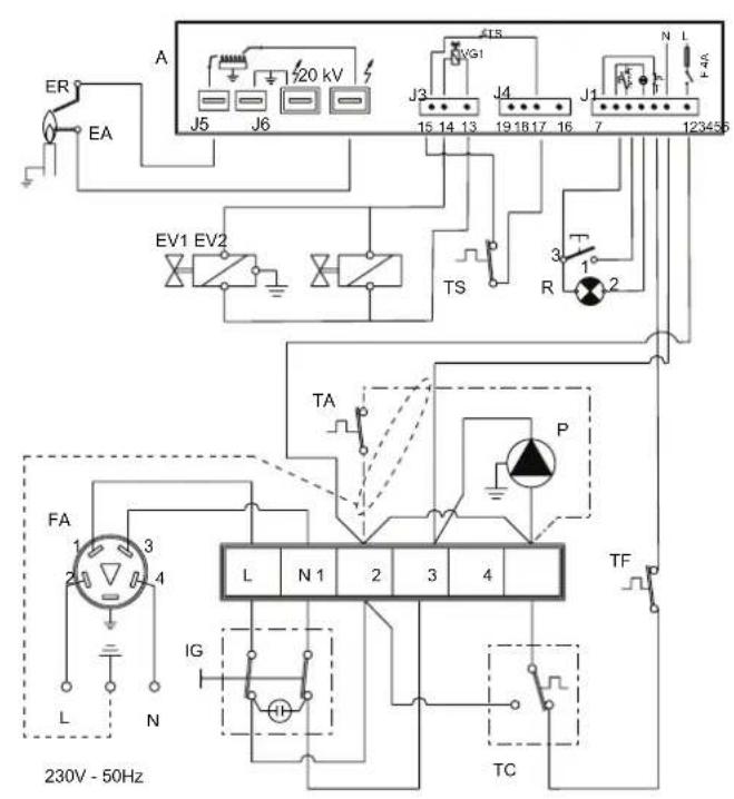
KEY
A Programmer
IG Main switch
TC Boiler stat
EA Ignition electrode
ER Ionisation electrode
P Circulating pump
TS Safety stat
EV1 Modulating coil
EV2 Modulating coil
TF Smoke stat
R Lock out lamp
TA Room stat
FA EMC filter
NOTE:
- When a room stat is to be fitted remove the link between terminal 1 and 4 on the connector plug.
- For the connection of the TA provide a shielded cable, connecting the shield to the earth node inside the instrument panel.
Fig. 4
3 CHARACTERISTICS
3.1 ELECTRONIC IGNITION
The boilers are equipped with electronic ignition without pilot flame; they are therefore equipped with an electric control and protection device. An electronic programmer, controls the ignition and the ionisation by means of two electrodes as shown in fig. 5.
Maximum safety is guaranteed because in case of accidental extinction of the burner the gas flow is stopped within 1 second. A reference mark made on the burner ensures the proper application of the ignition electrode.
3.1.1 Working cycle
Before lighting the boiler check with a voltmeter that the electric connection to the terminal board has been properly made observing the phase and neutral positions of the wiring diagram. Press the main switch on the control board; the lamp will light if there is power. At this stage
KEY
1 Ionisation electrode support
2 Ionisation electrode
3 Ignition electrode the boiler will start to work sending, via the programmer, a discharge current to the electrode and, at the same time, opening the gas valve. Normally the burner takes 1 or 2 seconds to light.
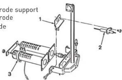
Fig. 5
It may however fail to light, in which case the boiler lock-out lamp will be activated. The main causes maybe:
- No gas supply
The equipment performs regularly sending voltage to the ignition electrode that continues to spark for max. 10 seconds, without detecting the burner starting, then it shuts
down.
It may occur at the first starting or when the boiler has not been used for a long period of time and there is air in the pipes. It may occur if the gas cock is closed or if the winding of one of the valve coils is interrupted, thus preventing it from opening.
- There is no spark
In the boiler you will only notice the gas flow to the burner, after 10 seconds it shuts down.
It may be due to the fact that the electrode cable is disconnected or is not properly fixed to the terminal 10; or the equipment transformer is burnt.
- No ionisation
From the time of the starting you can observe the electrode continuous sparking even if the burner is on. After 10 seconds the sparking stops and so does the burner, while the lock-out lamp appears to be on.
It occurs if the phase and neutral position on the terminal board has not been observed. The detection electrode cable is disconnected or the electrode itself is earthed; the electrode is very worn-out and needs replacing.
The sudden lack of voltage causes the immediate shutdown of the burner and when the voltage is restored the boiler will automatically restart.
3.1.2 Ionization circuit
The ionization circuit shall be checked with a normal microammeter, or even better, with a digital microammeter with a 0÷50 μA range. The microammeter terminals shall be electrically connected in series to the ionisation electrode cable. Under standard conditions the value varies from 4÷6 μA. The minimum ionization current value, at which the equipment may shut down, is approximately 1 μA. In this case it will be necessary to check that there is a good electric contact and to check the wear of the electrode tip and of its ceramic protection.
3.2 SMOKE SAFETY DEVICE
The smoke stat provides a protection against the discharge of flue gas into the atmosphere (3 fig. 2). This control device stops the gas valve if the flue gas is discharged into the boiler room is continuous way and in such quantities as to become dangerous.
To start the boiler again, switch off the power, then remove the smoke stat cover and reset the button below. If the thermostat continues to trip off, it will be necessary to check the flue thoroughly, making all the necessary changes to ensure it works properly.
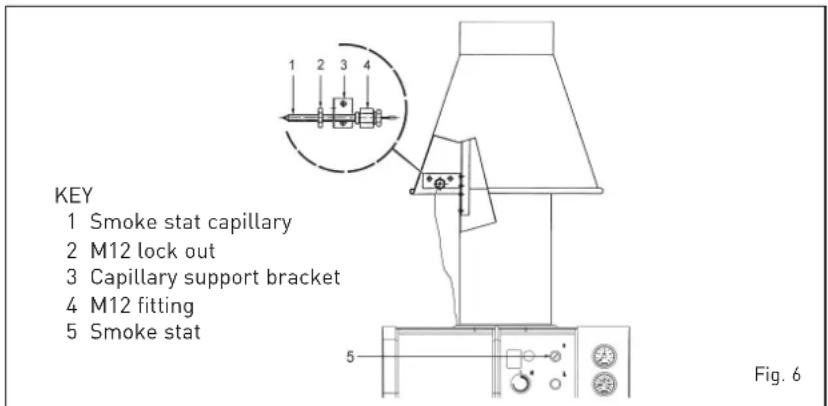
On the "RX 37÷55" models, the smoke stat capillary on the back of the boiler shall be put into the 12.5 ∅ hole of the droughtdiverter support bracket and fixed to it with the fitting and the M12 lock nut already mounted on the capillary (fig. 6).
3.3 SAFETY STAT
In case the boiler temperature exceeds 95°C the safety stat (6 fig. 2), will extinguish the pilot burner thus shutting off the gas flow to the pilot and main burner. "RX 19-26" models are equipped with safety stat with automatic resetting, and "RX 37÷55" with manual resetting. Should the stat with manual resetting trip off, it will be necessary to unscrew the cover and reset the button below for the pilot burner to restart.
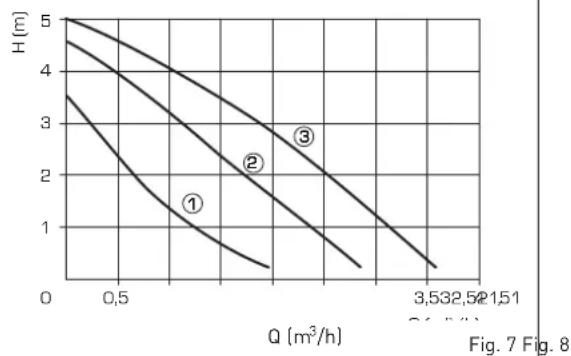
3.4 CIRCULATING PUMP PERFORMANCE CURVES
The "RX PVA" boilers can be equipped with either EURAMO NYL 40/25 or GRUNDFOS UPS 25/50 circulating pumps.
Both have a built-in speed selector for adjusting head and capacity. Head and capacity performance curves of the standard circulating pump, at different speeds, are given in fig. 7-8.
NOTE: Before starting the boiler check that the circulating pump is not locked.
EURAMO NYL 40/25 GRUNDFOS UPS 25/50
line
| Q (m³/h) | H (m) - Curve 1 | H (m) - Curve 2 | H (m) - Curve 3 | | -------- | --------------- | --------------- | --------------- | | 0 | 5 | 4.5 | 3.5 | | 0.5 | 3 | 3 | 2 | | 3.5 | 0.5 | 0.5 | 0.5 |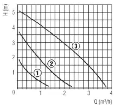
line
| Q (m³/h) | H (m) - Curve 1 | H (m) - Curve 2 | H (m) - Curve 3 | | -------- | --------------- | --------------- | --------------- | | 0 | 5 | 4 | 3 | | 1 | 1 | 2 | 1 | | 2 | 0.5 | 1 | 0.5 | | 3 | 0.2 | 0.5 | 0.2 | | 4 | 0 | 0 | 0 |4 USE AND MAINTENANCE
4.1 ADJUSTING GAS VALVE "19-26" VERSIONS
Standard "RX 19-26" boilers with electronic ignition feature a SIT 830 TANDEM gas valve (fig. 9). When the boiler is ignited for the first time, it is always better to purge the pipe through the pressure tap (3). Remove the plug on the pressure regulator (4) to adjust the main burner gas pressure.
The regulation is made by rotating the screw under the plug: rotate the screw clockwise to increase the pressure, anticlockwise to reduce it. The valve can control a "soft" ignition of the boiler through the screw (1). Rotate the screw anticlockwise to increase the burner "soft" ignition pressure (STEP), clockwise to reduce it. The optimum "soft" ignition values of the burner depend on the type of gas:
- Methane 3 - 4 mbar
- Butane 6 - 7 mbar
- Propane 6 - 7 mbar
4.2 ADJUSTING GAS VALVE "RX 37÷55" VERSIONS
The electronically ignited "RX 37÷55" boilers are equipped with the HONEYWELL VR4605C gas valve (fig.10).
When igniting the boiler for the first time, it is always advisable to purge the pipe by opening the inlet pressure tap (3). To adjust gas pressure to the main burner remove the plug on the pressure regulator (5).
Use a screwdriver to regulate the screw under the plug: to increase pressure screw clockwise, to reduce it screw counterclockwise.
4.3 ADJUSTING THE GAS PRESSURE TO BURNERS
Pressure calibration and gas input are carried out by the manufacturer. During installation of the equipment, feed pressure might be different from standard values.
It is therefore necessary to check pressure and gas input when igniting the boiler for the first time.
This test should be performed with the boiler in full operation (obviously no other gas appliances should be working at the same time). Read the gas meter twice every 6 minutes. Multiply the consumption by ten to
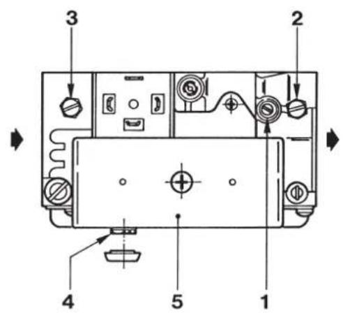
KEY
1 "Soft" igniter regulator
2 Outlet pressure tap
3 Inlet pressure tap
4 Main burner
adjusting screw
5 EV1 - EV2 coil
Fig. 9
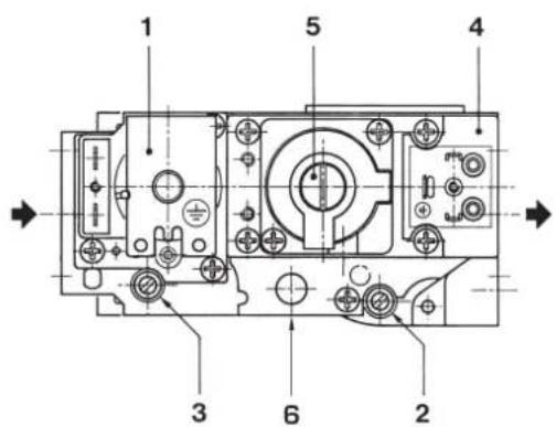
KEY
1 EV1 coil
2 Outlet pressure tap
3 Inlet pressure tap
4 EV2 coil
5 Pressure regulator
5 LPG adaptor
Fig. 10
calculate the consumption per hour. If this value does not correspond to the one in point 1.3, turn the screw of the pressure regulator on the valve until the exact value is obtained. Screw slowly and gradually. Read the gas meter at least thirty seconds after regulating the pressure.
4.4 GAS CONVERSION
A kit is supplied complete with the necessary change-over materials for operation with butane gas (G30) or propane gas (G31). Operate in the following manner for changing over from one gas to another:
- Replace the main nozzles and pilot nozzle supplied in a kit.
- Remove the plug on pressure
regulator and tighten the adjusting screw (4 fig. 9 - 5 fig. 10).
- Appy the adaptor outothe gas valve (6 fig. 10).
- Set valve input pressure at 30/37 mbar according to the type of gas by acting on the outer pressure reducer.
- When the working pressures have been adjusted, reseal the regulators.
- After have ultimately the conversion of the boiler, please stick onto the casing panel the plate showing the relevant feeding gas which is included into the kit.
NOTE: After assembling all the gas connections, a test for gas tightness must be carried out using soapy water or special products. Do not
use naked flames. The conversion to different gas must be carried out exclusively by authorized technical personnel.
4.5 REMOVING THE CASING
It is possible to completely disassemble the shell for an easy maintenance of the boiler following these simple instructions:
- Remove the boiler top which is fixed with pressure plugs.
- Remove the panelboard.
- To remove the door, unscrew completely the screw fixing the top hinge and lift the door, removing it from the fixed plug of the bottom hinge.
- Remove front and back panels by loosening the four nuts which fix them to the panels side.
- Remove the sides.
4.6 CLEANING AND MAINTENANCE
When the heating is turned off at the end of the season, it is compulsory to check the boiler and clean it as follows:
- Take off the boiler top.
- Remove the smoke chamber cleaning plate by unscrewing the fastening screws in the "RX 19-26" boilers.
- Remove the smoke chamber completely unscrewing the two nuts from the back side and the nut from the front side of "RX 37÷55" boilers.
- Extract the burner assembly by unscrewing the four screws which fix it to the valve flange.
- With the appropriate brush, reach down to the rows of plugs of the cast iron exchanger from the top and scrape off any scale with ver-
tical movements.
- Remove the burners from the nozzle holder header and throw a jet of air inside them so that any dust can be removed. Make sure that the top drilled part of the burners has no scale left.
- When disassembling and reassembling the burners be careful not to force any delicate parts, such as the thermocouple drill or the ignition unit.
- Scrape off any scale from the boiler bottom and reassemble all the parts checking the position of the gaskets.
- Check the stack making sure the flue is clean.
- Check the correct operation of the equipment.
After assembling all the gas connections, a test for gas tightness must be carried out using soapy water or special products. Do not use naked flames.
Maintenance and check of equipment and safety devices should be carried out at the end of each season only by authorized technical personnel.
4.7 FAULT FINDING
The burner does not ignite.
- This means that the flue smoke stat has tripped off (point 3.2)
- Make sure power arrives to the gas valve.
- Replace the electric operator of the valve.
- Replace the valve.
The boiler reaches the set temperature, but the radiators do not heat up.
- Make sure there are no air bubbles in the system, if so purge from appropriate air vents.
- The room stat is too low or must be replaced if faulty.
- The connections of the room stat are not correct. Make sure the cables are placed on terminals 1 and 4 of the boiler terminal board.
- The circulation pump is blocked, unblock it.
- The electric winding of the circulation pump is faulty, replace the pump.
The boiler pressure relief valve opens often.
- Make sure the system cold water pressure is not too high, follow the suggested values.
- If the pressure relief valve is faulty, replace it.
- Check pre-load pressure of the expansion tank.
- Replace the expansion tank if faulty.
The boiler gets dirty easily causing scaling of cast iron exchanger and cutting off of smoke stat.
- Make sure the main burner flame is well regulated and the gas consumption is proportional to the boiler output.
- The boiler is installed in a poorly ventilated room.
- Insufficient flue draught or not complying with existing standards
- The boiler operates at too low temperatures, set the boiler stat at higher temperatures.
The thermostat re-ignites with too high temperature drop.
- Replace the boiler stat which is faulty.
ATTENTION: Before performing any work on the boiler, make sure that the same and its components have cooled in order to prevent the risk of burns due to high temperatures.
WARNINGS
- In case of fault and/or incorrect equipment operation, deactivate it, without making any repairs or taking any direct action. Contact the nearest authorised technical personnel.
- The installation of the boiler and any servicing or maintenance job must be carried out by qualified personnel. Under no circumstances, the devices sealed by the manufacturer can be tampered with.
- It is absolutely prohibited to block the intake grilles and the aeration opening of the room where the equipment is installed.
To ignite the boilers "RX" it is enough to switch on the switch (1) to make the boiler operate and begin heating.
ADJUSTMENT OF HEATING TEMPERATURE
The heating temperature can be adjusted with the stat knob with a range from 45^ C to 85^ C (16 fig. 11). The temperature setting can be checked on the thermometer (5 fig. 11). For an always optimum operation of the boiler we recommend not to reduce the operating temperature below 60^ C.
If the burner does not ignite lock-out lamp will be activated (2 fig. 11). Press the resetting button to make the boiler automatically start.
If, after trying to release the boiler two or three times, this does not regularly start, call on the authorized technical personnel.
SWITCHING OFF THE BOILER
To switch off the boilers "RX" it is
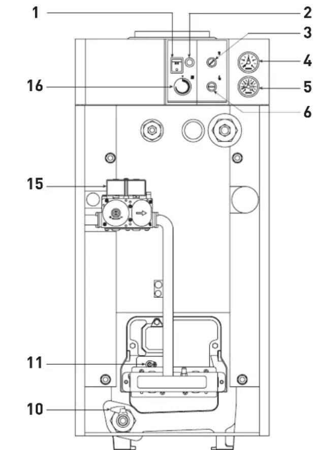
KEY
1 Main switch
2 Lock out lamp
3 Smoke stat
4 Hydrometer
5 Thermometer
6 Safety stat
10 Drain cock (1/2")
11Detectionelectrode
15Gasvalve
16 Boiler stat
Fig. 11
enough to turn off the switch (1 fig. 11) to turn off the boiler. Close the gas pipe cock if you are not going to use the boiler for a long time.
SAFETY STAT
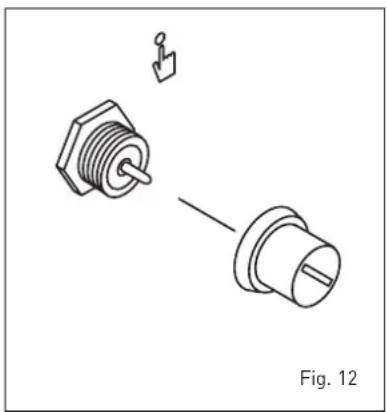
"RX 37÷55" models are equipped with safety stat (6 fig. 11) with manual resetting. In case the boiler temperature exceeds 95°C the safety stat will extinguish the pilot burner thus shutting off the gas flow to the pilot and main burner. Should the stat trip off, it will be necessary to unscrew the cover and reset the button below for the pilot burner to restart (fig. 12).
Should the boiler "lock out" again, you must call the authorized technical staff.
SMOKE SAFETY DEVICE
It is a safety device which controls the correct discharge of flue gas into the atmosphere (3 fig. 11).
The control device stops the gas valve if the flue gas is discharged into the boiler room is continuous way and in such quantities as to become dangerous.
To start the boiler again, switch off the power, then remove the smoke stat cover and reset the button below (fig. 12).
If the boiler stops again, it will be necessary to call the authorized technical staff.
natural_image
Technical line drawing of two mechanical components with a pin and shaft, labeled Fig. 12 (no text or symbols on the components themselves)SYSTEM FILLING
Check periodically that the hydrometer (4 fig. 11) has pressure values at a switched-off system of 1 - 1,2 bar.
If the pressure is less than 1 bar, re-charge it rotating the knob anticlockwise. After the operation check that the tap is properly closed.
Should the pressure exceed the foreseen limit, discharge the superfluous amount by operating on the vent knob of any radiator.
GAS CONVERSION
Should a gas other than that for which the boiler is equipped be used, the conversion has to be carried out by technical personnel authorized by the manufacturer.
LEANING AND MAINTENANCE
When the heating is turned off at the end of the season, it is compulsory to check the boiler and clean it.
Maintenance and check of equipment and safety devices shall be carried out only by authorized technical personnel.
The boiler is supplied with an electric cable. Should this require replacement, get in touch exclusively with the authorized technical staff.
ATTENTION: Before performing any work on the boiler, make sure that the same and its components have cooled in order to prevent the risk of burns due to high temperatures.
DISPOSAL OF THE EQUIPMENT
Once it reaches the end of its operating life, the equipment MUST BE RECYCLED in line with current legislation.
IT MUST NOT be disposed of together with urban waste.
It can be handed over to recycling centres, if there are any, or to retailers that offer this service.
Recycling prevents potential dama-
ge to the environment and health. It allows to recover a number of recyclable materials, with considerable savings in terms of money and energy.
ОГЛАВЛЕНИЕ
natural_image
Technical line drawing of a mechanical setup with a central lamp and vertical dimension labeled 'H' (no text or symbols beyond the label)- aspect: eventual limpede
- pH: 6÷8
- duritate: < 25^ .
In cazul in care caracteristicile apei
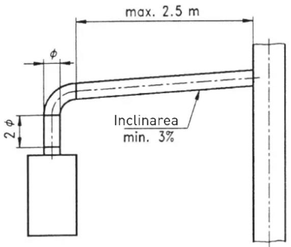
Fig. 4
TA Regulator climatic
FA Filtru separator
NOTA:
- In cazul in care conectati TA, indepartati puntea existenta intre regletele 1-4.
natural_image
Technical illustration of two mechanical components with a pin inserted, labeled Fig. 13 (no text or symbols on the components themselves)TERMOSTATUL DE GAZE ARSE
Este un dispozitiv de siguranta care, impiedica refluxul gazelor arse in incapere, in cazul ineficacitatii sau obturarii partiale a conductei de evacuare a gazelor arse (pozitia 3/figura 12).
- INDICE
- UTILISATION ET ENTRETIEN
- RÉGULATION SOUPAPE GAZ VERSION "RX19-26"
- IMPORTANT
- DESCRIPTION OF THE BOILER
- INTRODUCTION
- 1.2DIMENSIONS
- "RX 19-26" versions
- MAIN COMPONENTS
- BOILER CIRCUIT LOAD LOSS
- INSTALLATION
- BOILER ROOM AND VENTILATION
- BOILER CONNECTION
- Filter on the gas pipe
- SYSTEM FILLING
- System water treatment
- FLUE
- Flue connection
- ELECTRIC CONNECTION
- INSTALLATION WARNINGS
- WARNING
- ATTENTION
- Wiring diagram
- NOTE:
- CHARACTERISTICS
- ELECTRONIC IGNITION
- Working cycle
- - No gas supply
- - There is no spark
- - No ionisation
- Ionization circuit
- SMOKE SAFETY DEVICE
- SAFETY STAT
- CIRCULATING PUMP PERFORMANCE CURVES
- USE AND MAINTENANCE
- ADJUSTING GAS VALVE "19-26" VERSIONS
- ADJUSTING GAS VALVE "RX 37÷55" VERSIONS
- ADJUSTING THE GAS PRESSURE TO BURNERS
- GAS CONVERSION
- REMOVING THE CASING
- CLEANING AND MAINTENANCE
- FAULT FINDING
- The burner does not ignite.
- The boiler pressure relief valve opens often.
- The boiler gets dirty easily causing scaling of cast iron exchanger and cutting off of smoke stat.
- The thermostat re-ignites with too high temperature drop.
- WARNINGS
- ADJUSTMENT OF HEATING TEMPERATURE
- SWITCHING OFF THE BOILER
- SAFETY STAT
- SMOKE SAFETY DEVICE
- SYSTEM FILLING
- GAS CONVERSION
- LEANING AND MAINTENANCE
- DISPOSAL OF THE EQUIPMENT
- ОГЛАВЛЕНИЕ
- NOTA:
- TERMOSTATUL DE GAZE ARSE
Brand : SIME
Model : RX
Category : Boiler