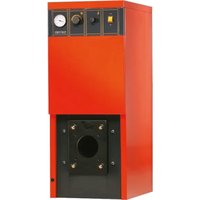
AR - Boiler SIME - Free user manual and instructions
Find the device manual for free AR SIME in PDF.


| Brand | SIME |
| Model | AR |
| Product type | Cast iron oil-fired boiler |
| Category | Central heating boiler |
| Fuel | Heating oil (fuel oil) |
| Useful output (model AR4) | 29.4 kW |
| Nominal heat input (AR4) | 33.4 kW |
| Maximum working pressure | 4 bar |
| Water content (AR4) | 23 litres |
| Depth (AR4) | 495 mm |
| Weight (AR4) | 122 kg |
| Power supply | 230 V - 50 Hz single-phase |
| Body material | Cast iron |
| Number of sections (AR4) | 4 |
| Heating connection | 1 1/2" |
| Drain connection | 1/2" |
| Efficiency | High (balanced combustion) |
| Temperature control | Adjustable boiler aquastat |
| Safety | Safety aquastat, mandatory earthing |
| Maintenance | Annual sweeping, cleaning by qualified installer |
| Supplied accessories | Insulating jacket, fiberglass wool, instrument panel |
| Test certificate | Inserted in the combustion chamber to be kept |
Frequently Asked Questions - AR SIME
User questions about AR SIME
0 question about this device. Answer the ones you know or ask your own.
Ask a new question about this device
Download the instructions for your Boiler in PDF format for free! Find your manual AR - SIME and take your electronic device back in hand. On this page are published all the documents necessary for the use of your device. AR by SIME.
USER MANUAL AR SIME
AR
Fig. 3
Remove the "Testing Certificate" from inside the combustion chamber and keep together with the instructions manual
CONTENTS
1 BOILER DESCRIPTION
1.1 INTRODUCTION 6
1.2 DIMENSIONS
1.3 TECHNICAL FEATURES
1.4 COMBUSTION CHAMBER DIMENSIONS
2 INSTALLATION
2.1 BOILER ROOM 7
2.2 BOILER ROOM DIMENSIONS
2.3 CONNECTING UP SYSTEM
2.4 CONNECTING UP FLUE
2.5 FITTING THE CASING
2.6 ELECTRICAL CONNECTION 8
3 USE AND MAINTENANCE
3.1 COMMISSIONING THE BOILER 9
3.2 LIGHTING THE BOILER
3.3 CLEANING THE BOILER
1 BOILER DESCRIPTION
1.1 INTRODUCTION
The new "AR" series of cast iron boilers has been designed in compliance with all applicable safety standards. They use light oil and have a perfectly balanced combustion with a very high thermal efficiency for economical performance.
The components for "AR" installation are supplied in two separate packages: boiler body, casing with enclosed documents and control panel.
1.2 DIMENSIONS
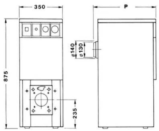
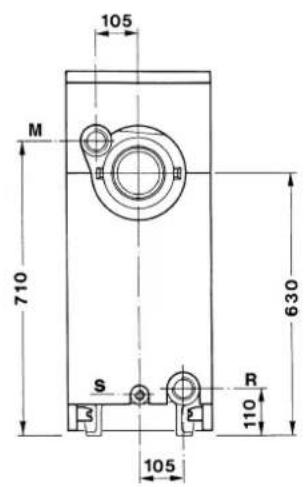
M C.H. flow 1^1/2
R C.H. return 1^1/2
S Boiler filling drain 1/2"
Fig. 1
1.3 TECHNICAL FEATURES
| AR3 AR4 AR5 | ||||
| Output kW 18.9 29.4 40.0 | ||||
| kcal/h | 16,300 | 25,300 | 34,400 | |
| Input | kW | 21.5 | 33.4 | 45.4 |
| kcal/h | 18,500 | 28,700 | 39,000 | |
| P Depth | mm | 395 | 495 | 595 |
| Number of sections | 3 | 4 | 5 | |
| Maximum water head | bar | 4 | 4 | 4 |
| Water content | l | 19 | 23 | 27 |
| Smoke Δp | mbar | 0.10 | 0.12 | 0.16 |
| Water Δp (Δt 10°C) | mbar | 1.80 | 2.50 | 3.50 |
| Combustion capacity | kg/h | 2.04 | 2.93 | 3.97 |
| Injector flow rate | gall/h | 0.50 | 0.65 | 1.00 |
| Atomising angle | 80°R | 60° | 60° | |
| Atomising pressure | kg/cm2 | 8.5 | 12.0 | 9.7 |
| Weight | kg | 92 | 122 | 147 |
1.4 COMBUSTION CHAMBER DIMENSIONS
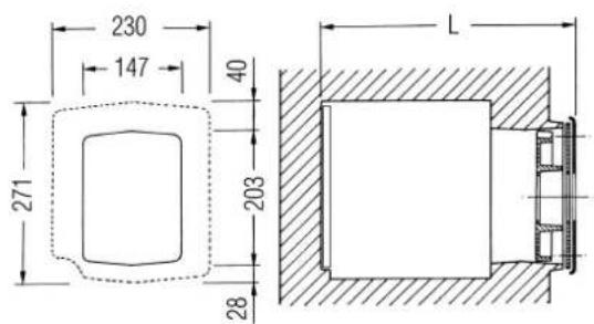
| AR3 | AR4 | AR5 | |
| L mm | 277 | 377 | 477 |
| Volumen m^3 | 0.013109 | 0.019028 | 0.024947 |
Fig. 2
2 INSTALLATION
2.1 BOILER ROOM
The boiler room should feature all the characteristics required by standards governing liquid fuel heating systems.
2.2 BOILER ROOM DIMENSIONS
Position the boiler body on the foundation bed, which should be at least 10 cm high. The body should rest on a surface allowing shifting, possibly by means of sheet metal.
Leave a clearance between the boiler and the wall of at least 0.60 m, and between the top of the casing and the ceiling of 1 m (0.50 m in the case of boilers with incorporated D.H.W. tank). The ceiling height of the boiler room should be less than 2.5 m.
2.3 CONNECTING UP SYSTEM
When connecting up the water supply to the boiler, make sure that the specifications given in fig. 1 are observed. Make connections with rigid unions or flexible steel hoses that do not place the unit under strain. All connecting unions should be easy to disconnect by means of tightening rings.
2.3.1 Filling the water system
Before connecting the boiler, thoroughly flush the system to eliminate scale which could damage the appliance.
Filling must be done slowly so as to allow any air bubbles to be bled off through the air valves.
In closed-circuit heating systems, the cold water filling pressure and the pre-charging pressure of the expansion vessel should be no less than or equal to the height of the water head of the installation [e.g. for water head of 5 metres, the vessel pre-charging pressure and installation filling pressure should be at least 0.5 bar].
2.3.2 Water system characteristics
THE WATER USED FOR THE CENTRAL HEATING SYSTEM SHOULD BE TREATED IN THE FOLLOWING CASES:
- For extensive systems (with high contents of water).
- Frequent addition of water into the system.
- Should it be necessary to empty the system either partially or totally.
2.4 CONNECTING UP FLUE
The flue is of fundamental importance for the proper operation of the boiler; if not installed in compliance with the standards, starting the boiler will be difficult and there will be a consequent formation of soot, condensate and encrustation.
The flue used to expel combustion products into the atmosphere must meet the following requirements:
- be constructed with waterproof materials, and resistant to smoke temperature and condensate;
- be of adequate mechanical resilience and of low heat conductivity;
- be perfectly sealed to prevent cooling of the flue itself;
- be as vertical as possible; the terminal section of the flue must be fitted with a static exhaust device that ensures constant and efficient extraction of products generated by combustion;
- to prevent the wind from creating pressure zones around the chimney top greater than the uplift force of combustion gases, the exhaust outlet should be at least 0.4 m higher than structures adjacent to the stack (including the roof top) within 8 m;
- have a diameter that is not inferior to that of the boiler union: square or
rectangular-section flues should have an internal section 10% greater than that of the boiler union;
- the useful section of the flue must conform to the following formula:
$$ S = K \frac {P}{\sqrt {H}} $$
S resulting section in cm 2
K reduction coefficient for liquid fuels:
- 0.045 for firewood
- 0.030 for coal
- 0.024 for light oil
- 0.016 for gas
P boiler input in kcal/h
H height of flue in metres, measured from the flame axis to the top of the flue reduced by:
- 0.50 m for each change of direction of the connection union between boiler and flue;
- 1.00 m for each metre of union itself.
2.5 FITTING THE CASING
The casing and the control panel are supplied in separate cardboard package. The housing package also contains the boiler documents and the glass wool for insulating the cast iron body. To fit the casing, proceed as follows (fig. 3):
- Remove the four screws, then the burner plate.
- Position the glass wool (2), secure the front panel (3) with the nuts sup-
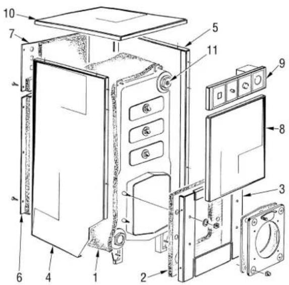
Fig. 3
plied, then refit the burner plate.
- Place de glass fibre (1) around the boiler body.
- Mount the left (4) and right (5) sides introducing the slot of the rear fold between the two nuts on the tie-rods.
- Secure the sides to the front panel (3) by means of the pins.
- Secure the two rear panels (6) and (7) to the sides with the ten tapping screws supplied.
- Secure the front panel (8) to the sides by means of the pins.
- Mount the control panel (9) by means of the pins.
Prior to performing the above operation, unwind the capillary tubes of the two thermostats and of the thermometer by inserting the respective probes in the holder (11), then lock with the spring supplied. It is recommended to complete all electrical connections as shown in the paragraph 2.6.
- Complete assembly by securing the cover [10] to the sides.
NOTE: Remove the "Testing Certificate" from inside the combustion chamber and keep together with the instructions manual.
2.6 ELECTRICAL CONNECTION
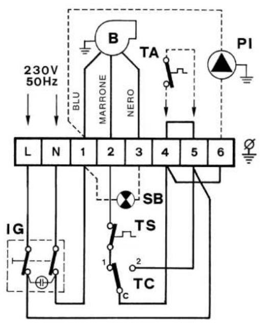
The boiler is fitted with an electricity cable, and requires a single-phase power supply of 230V - 50Hz through
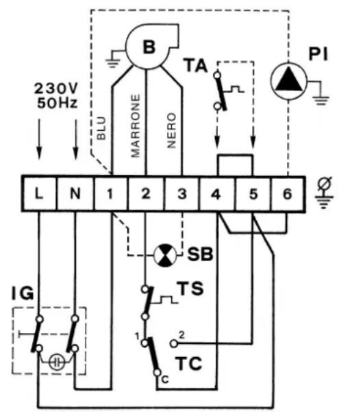
KEY
TS H.L. stat
TA Room stat (*)
TC Boiler stat
IG Main switch
PI C.H. pump [*]
B Burner [*]
SB Burner lock-out lamp
[*] Not supplied
Fig. 4
the main switch protected by fuses.
The room thermostat (required for enhanced room temperature control) should be installed as shown in fig. 4.
Connect the burner power cables
supplied.
NOTE: SIME declines all responsibility for injury caused to persons due to failure to earth the boiler.
3 USE AND MAINTENANCE
3.1 COMMISSIONING THE BOILER
When commissioning the boiler always make sure that:
- No flammable liquids or materials are near the boiler.
- The electrical connections to the mains and the earthing are correct.
- The flue and chimney are free from obstructions.
- The flow and return valves are fully open.
- The system has been filled with water and adequately vented.
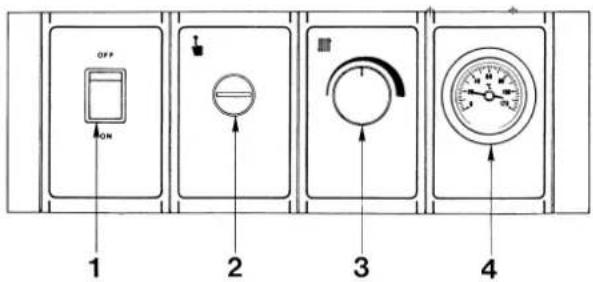
Fig. 5
To light the boiler proceed as follows (fig. 5):
- Check that the "Testing Certificate" has been removed from inside the combustion chamber.
- Switch on the main switch [1]; the burner will start immediately or after a few minutes if there is a preheater.
- Turn the operation thermostat knob (3) to the desired setting.
3.3 CLEANING THE BOILER
The boiler body and flue should be cleaned at the end of each season. The baffles (2 fig. 6) must be removed before cleaning operations.
Once maintenance has been completed, reposition the baffles. Use the pig (1 fig. 6) to clean the smoke pipes.
NOTE: Preventive maintenance must be carried out by authorized technical staff.
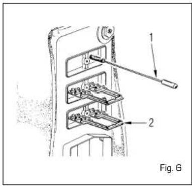
Fig. 3
- AR
- CONTENTS
- BOILER DESCRIPTION
- INSTALLATION
- USE AND MAINTENANCE
- INTRODUCTION
- DIMENSIONS
- TECHNICAL FEATURES
- COMBUSTION CHAMBER DIMENSIONS
- BOILER ROOM
- BOILER ROOM DIMENSIONS
- CONNECTING UP SYSTEM
- Filling the water system
- Water system characteristics
- CONNECTING UP FLUE
- FITTING THE CASING
- ELECTRICAL CONNECTION
- COMMISSIONING THE BOILER
- CLEANING THE BOILER
Brand : SIME
Model : AR
Category : Boiler