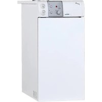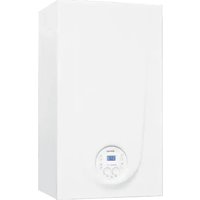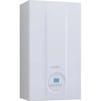
Brava Slim BF - Boiler SIME - Free user manual and instructions
Find the device manual for free Brava Slim BF SIME in PDF.


User questions about Brava Slim BF SIME
0 question about this device. Answer the ones you know or ask your own.
Ask a new question about this device
Download the instructions for your Boiler in PDF format for free! Find your manual Brava Slim BF - SIME and take your electronic device back in hand. On this page are published all the documents necessary for the use of your device. Brava Slim BF by SIME.
USER MANUAL Brava Slim BF SIME
Low temperature wall mounted boiler
BRAVA SLIM BF
MANUEL POUR L'UTILISATION, L'INSTALLATION ET L'ENTRETIEN USER, INSTALLATION AND SERVICING INSTRUCTIONS
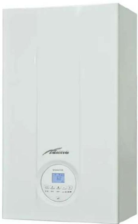
natural_image
White industrial water heater with digital display and control buttons (no visible text or symbols)FR
EN
Pour consulter la documentation,
To consult the documentation, visit our
website www.sime.it
Fonderie SIME S.p.A.
6328417 - 01/2022 - R1
AVERTISSEMENTS ET RÈGLES DE SÉCURITÉ

AVERTISSEMENTS
text_image
SET 40°C l l bar1.6 Codes anomalies / pannes
natural_image
Simple line drawing of a dog jumping out of a horizontal surface (no text or symbols)text_image
Technical diagram of an industrial machine with numbered components for identificationtext_image
Technical diagram of a mechanical device with numbered components for identificationFig. 9
5.4.2 Brava Slim 40 BF
text_image
Technical diagram of an internal air conditioning unit with numbered components for identificationtext_image
Technical diagram of a mechanical device with numbered components labeled 11 through 16.Fig. 10
5.6 Circuit hydraulique principal
text_image
1 2 3 4 5 6 7 8 MUGER 11 12 14 S 15 16 9 10 17 Fig. 11LÉGENDE :
natural_image
Isometric line drawing of a rectangular box with internal compartments and a diagonal stripe (no text or symbols)Fig. 15
natural_image
Technical line drawing of a rectangular industrial enclosure with labeled dimensions H, L, and P (no text or symbols beyond labels)Fig. 16
| Description | Brava Slim BF | ||
| 25 30 40 | |||
| L (mm) 400 450 450 | |||
| P (mm) 250 250 340 | |||
| H (mm) 700 700 700 | |||
| Poids (kg) 29 31,5 36 | |||
6.3 Déplacement
natural_image
Illustration of hands holding a box with a circular emblem and a diamond-shaped object, showing motion arrows (no text or symbols)
IL EST INTERDIT
text_image
Technical diagram of a refrigerator with labeled parts and structural annotationsFig. 19

AVERTISSEMENTS
6.9 Raccordements hydrauliques
natural_image
Technical diagram of a mechanical housing or enclosure with labeled components and an arrow indicating direction (no text or symbols present)Fig. 22
text_image
Diagram showing electrical circuit symbols including a diode, power source, and ground symbol with Chinese labels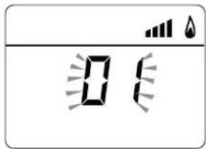
text_image
Digital display showing '0' with battery icons above it, likely indicating a timer or digital status.text_image
Diagram showing electrical circuit symbols including power source, diode, and ground symbol with Chinese labels
text_image
0 16text_image
P 111 1 P
text_image
00natural_image
Simple diagram with a rocket icon and radiating lines, no text or symbols presentSAFETY WARNINGS AND REGULATIONS

WARNINGS
- After having removed the packaging make sure that the product supplied is integral and complete in all its parts. If this is not the case, please contact the Dealer who sold the appliance.
- The appliance must be used as intended by Sime who is not responsible for any damage caused to persons, animals or things, improper installation, adjustment, maintenance and improper use of the appliance.
- In the event of water leaks, disconnect the appliance from the mains power supply, close the water mains and promptly inform professionally qualified personnel.
- Periodically check that the operating pressure of the water heating system when cold is 1-1.2 bar. If this is not the case, increase the pressure or contact professionally qualified personnel.
- If the appliance is not used for a long period of time, at least one of the following operations must be carried out:
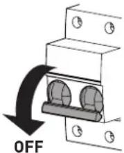
-set the main system switch to "OFF";
-close the gas and water valves for the water heating system.
- In order to ensure optimal appliance operations Sime recommends that maintenance and checks are carried out ONCE A YEAR.
- If the power cable is damaged, replace it with a cable ordered as a spare part with the same characteristics (type X). Assembly must be by carried out by a qualified professional.

WARNINGS
- It is recommended that all operators read this manual carefully in order to use the appliance in a safe and rational manner.
- This manual is an integral part of the appliance. It must therefore be kept for future reference and must always accompany the appliance in the event the appliance is transferred or sold to another Owner or User or is installed on another system.
- Installation and maintenance of this appliance must be carried out by a qualified company or by a professionally qualified technician in accordance with the instructions contained in the manual. Once the work is complete, the company or technician will issue a declaration of conformity with national and local technical standards and legislation in force in the country where the appliance will be used.
- Any repairs on the appliance must be carried out solely by professionally qualified personnel, using original spare parts only. Failure to comply with these instructions can jeopardise the appliance's safety and void the warranty with immediate effect.
- Fonderie SIME S.p.A. reserves the right to make improvements to its products at any time without prior notice, without compromising their essential characteristics. The graphic illustrations and/or images in this document may show optional accessories that vary according to the country in which the appliance is used.
RESTRICTIONS

IT IS FORBIDDEN
- To allow children under the age of 8 to use the appliance. The appliance can be used by children no younger than 8 years old, by people with physical or cognitive disabilities, and by people lacking experience or the necessary knowledge, provided that they are supervised or have been instructed on how to use the appliance safely and that they understand the risks associated with it.
- To allow children to play with the appliance.
- To allow unsupervised children to perform user maintenance and cleaning.
-
To use electrical devices or appliances such as switches, electrical appliances etc if you can smell fuel. If this should happen:
-
open the doors and windows to air the room;
-
close the gas isolation device;
-promptly call for professional assistance. -
To touch the appliance with bare feet or with any wet part of the body.
- To carry out any technical intervention or cleaning operation before having disconnected the appliance from the mains power by setting the main switch to "OFF", and closing the gas supply.
- To modify the safety or adjustment devices without authorization and instructions from the manufacturer.

IT IS FORBIDDEN
- To block the condensate drain (if present).
- To pull, detach or twist the electrical cables coming out of the appliance even if the appliance is disconnected from the mains power supply.
- To expose the boiler to atmospheric agents. These boilers can also be installed in partially covered areas, as per EN 15502, with a maximum ambient temperature of 60^ and a minimum ambient temperature of -5^ . It is recommended that the boiler is installed below weathered roofs, on the balcony or in a protected niche, to protect it from exposure to weathering agents (rain, hail and snow). The boiler is equipped as standard with an antifreeze function.
- To block or reduce the size of the ventilation openings of the room where the appliance is installed, if present.
- Remove the mains power and gas supply from the appliance if the external temperature could fall below ZERO (risk of freezing).
- To leave containers with flammable substances in the room where the appliance is installed.
- To dispose of the packaging material irresponsibly as it could be dangerous. Packaging must be disposed of as specified by the legislation in force in the country where the appliance will be used.
Dear Customer,
Thank you for purchasing a Sime Brava Slim BF boiler, a new-generation low-temperature modulating device possessing technical and performance characteristics capable of satisfying your space heating and instant domestic hot water requirements with the utmost safety and with limited running costs.
RANGE
| MODEL CODE | |
| Brava Slim 25 BF[G20] | 8112500 |
| Brava Slim 25 BF[G30/G31] | 8112501 |
| Brava Slim 30 BF[G20] | 8112502 |
| Brava Slim 30 BF[G30/G31] | 8112503 |
| Brava Slim 40 BF[G20] | 8112506 |
COMPLIANCE
Our company declares that Brava Slim BF boilers comply with the following directives:
– Gas Appliances EU Regulation 2016/426
- Boiler Efficiency Directive 92/42/EEC
- Low Voltage Directive 2014/35/EU
- Electromagnetic Compatibility Directive 2014/30/EU
SYMBOLS

WARNING
To indicate actions which, if not carried out correctly, can result in injury of a general nature or may damage or cause the appliance to malfunction; these actions therefore require particular caution and adequate preparation.

ELECTRICAL HAZARD
To indicate actions which, if not carried out correctly, could lead to injury of an electrical nature; these actions therefore require particular caution and adequate preparation.

IT IS FORBIDDEN
To indicate actions which MUST NOT BE carried out.

CAUTION
To indicate particularly important and useful information.
MANUAL STRUCTURE
This manual is organized as follows.
USER INSTRUCTIONS
TABLE OF CONTENTS 47
DESCRIPTION OF THE APPLIANCE
TABLE OF CONTENTS 53
INSTALLATION AND SERVICING INSTRUCTIONS
TABLE OF CONTENTS 61
USER INSTRUCTIONS
TABLE OF CONTENTS
1 USING THE BOILER BRAVA SLIM BF 48
1.1 Control panel 48
1.2 Preliminary checks 49
1.3 Ignition 49
1.4 Adjusting the heating temperature ..... 49
1.5 Adjusting the domestic hot water temperature ..... 49
1.6 Fault / malfunction codes 50
1.6.1 Maintenance request 50
2 SHUTDOWN 50
2.1 Temporary shutdown....50
2.2 Shutting down for long periods 51
3 MAINTENANCE 51
3.1 Adjustments....51
3.2 External cleaning....51
3.2.1 Cleaning the cladding.... 51
4 DISPOSAL 51
4.2.2 Brava Slim 25 BF ÷ Brava Slim 30 BF ..... 51
4.2.3 Brava Slim 40 BF 51
1 USING THE BOILER BRAVA SLIM BF
1.1 Control panel
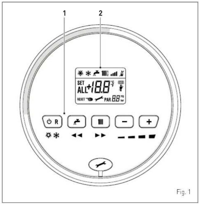
OR If pressed once or more than once for at least 1 second during normal operation, this button allows the user to change the boiler operating mode in a cyclical sequence (Stand-by - Summer - Winter). If the boiler is experiencing a fault which can be reset, it allows boiler operation to be unblocked.
During normal operation, pressing the button displays the domestic hot water set point which can be between 10 and 60°C. In "parameter setting", the user can scroll through the parameter index (decreasing) by pressing this button.
During normal operation, pressing the button displays the heating set point which can be between 20 and 80°C. In "parameter setting", the user can scroll through the parameter index (increasing) by pressing this button.
During normal operation, pressing this button allows the user to reduce the heating or DHW set point on the basis of the selection made previously. If there is a Remote Control (Open Therm), after having selected the heating button, the user can modify the incline of the climatic curve (decreasing it) by pressing the button (-). In "parameter setting/display", the user can modify the parameter setting or value (decreasing) by pressing this button.
+ During normal operation, pressing this button allows the user to increase the heating or DHW set point on the basis of the selection made previously. If there is a Remote Control (Open Therm), after having selected the heating button, the user can modify the incline of the climatic curve (increasing it) by pressing the button (+). In "parameter setting/display", the user can modify the parameter setting or value (increasing) by pressing this button.
Programming connector cover plug.
NOTE: pressing any one of these buttons for more than 30 seconds generates a fault on the display without preventing boiler operation. The warning disappears when normal conditions are restored.
2 DISPLAY
“SUMMER”. This symbol appears when the boiler is operating in “Summer” mode or if only the domestic hot water mode is enabled via the remote control. If the symbols and are flashing, this indicates that the chimney sweep function is active.
"WINTER". This symbol appears when the boiler is operating in "Winter" mode or if both the domestic hot water and heating modes are enabled via the remote control. With the remote control, if no operating modes have been enabled both symbols and will be off.
RESET "RESET REQUIRED". The message indicates that after having repaired the fault, normal boiler operation can be restored by pressing the button OR.
"DOMESTIC HOT WATER". This symbol is present during a DHW request or during the "chimney sweep function" It flashes during the selection of the domestic hot water set point.
"HEATING". This symbol lights up during heating operation or during the "chimney sweep function It flashes during the selection of the heating set point.
"A BLOCK" DUE TO NO FLAME.
"FLAME PRESENCE".
"POWER LEVEL". This indicates the power level at which the boiler is operating.
PAR "PARAMETER". This indicates that the user may be in parameter setting/display, or "info" or "counter", or in "activated alarms" (history).
ALL "ALARM". This indicates that a fault has occurred. The number specifies the cause which generated the alarm.
"CHIMNEY SWEEP". This indicates that the "chimney sweep function" has been activated.
. . . bar "HEATING SYSTEM PRESSURE". Display of heating system pressure.
ECO "ECO", ALTERNATIVE ENERGY SOURCES. Where active, it indicates that there is a solar system available.
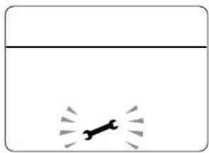
"MAINTENANCE REQUEST". If active, it shows it is time to perform maintenance on the boiler.
1.2 Preliminary checks

WARNING
- Should it be necessary to access the areas in the bottom part of the appliance, make sure that the system components and pipes are not hot (risk of burning).
- Before replenishing the heating system, put on protective gloves.
Commissioning of the Brava Slim BF boiler must be carried out by professionally qualified technicians, after which the boiler can operate automatically. It may, however, be necessary for the user to start the appliance autonomously without involving a technician: for example, after a holiday.
First of all check that the gas isolation and water system valves are open.
1.3 Ignition
After having carried out the preliminary checks, perform the following to start the boiler:
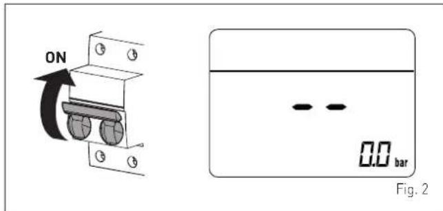
- set the main system switch to "ON" in order for the display to show the pressure level in the system during refilling
- make sure that the operating mode is set to "Stand-by"; if this is not the case, press the button ⏻R until "Stand-by" mode has been selected
text_image
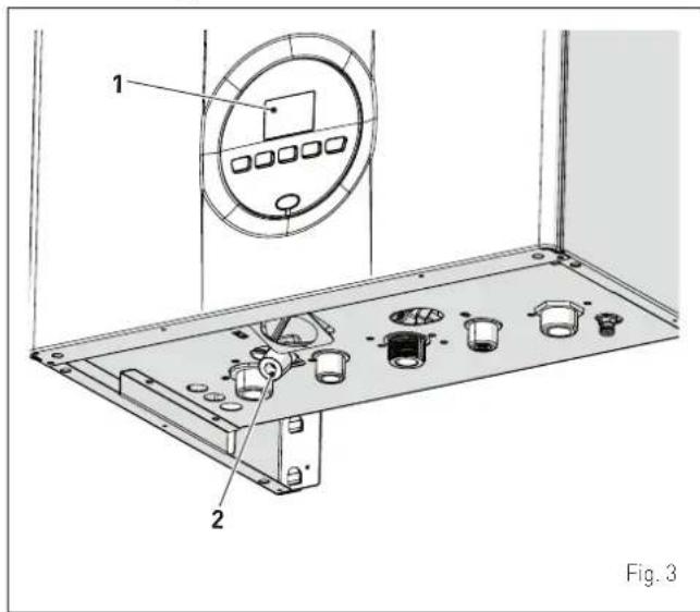
ON 0.0 bar Fig. 2- on the display (1), check that the heating system pressure when cold is 1-1.2 bar. If this is not the case, open the filling valve (2) and restore the heating system pressure until the display (1) shows a reading of 1-1.2 bar
- close the filling valve (2)
text_image
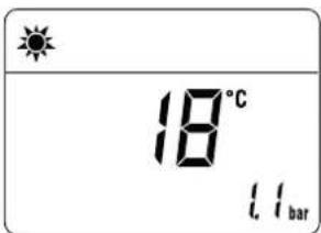
1 2 Fig. 3- select the "SUMMER" operating mode by pressing and holding the 🔊Rbutton for at least 1 second. the value of the delivery sensor detected at that moment will appear on the display

text_image
18°C 11 bar- open one or more than one hot water tap. The boiler will work at maximum power until the taps are closed.
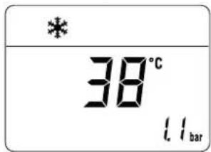
Once the boiler has been commissioned in "SUMMER mode" "WINTER mode" can be selected by pressing and holding the button OR for at least 1 second. The value of the delivery water temperature detected at that moment will appear on the display. In this case it is necessary to adjust the air thermostat/s to the required temperature or if the system has a chrono-thermostat, check that this is "active" and adjusted.
text_image
* 38°C 1.1 bar1.4 Adjusting the heating temperature
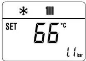
If the heating temperature is to be increased or decreased, press the button followed by the buttons + or - until the desired temperature is reached. The temperature can be set to between 20 and 80°C.
text_image
* 1111 SET 66°C 11bar1.5 Adjusting the domestic hot water temperature
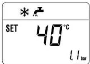
If the domestic hot water temperature is to be increased or decreased, press the button _2 followed by the buttons + or - until the desired temperature is reached. The temperature can be set to between 10 and 60°C.
text_image
SET 40°C 11 bar1.6 Fault / malfunction codes
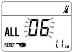
If a fault/malfunction is detected during boiler operation, the message "ALL" will appear on the display followed by the fault code.
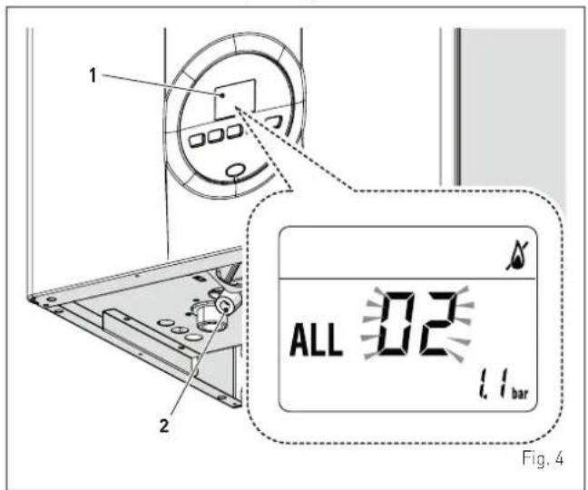
If you see alarm "02" (low water pressure in the system):
- on the display (1), check that the heating system pressure when cold is 1-1.2 bar. If this is not the case, open the filling valve (2) and restore the heating system pressure until the display (1) shows a reading of 1-1.2 bar
- close the filling valve (2)
- press and hold the button ⏻R for more than 3 seconds and check whether normal operating conditions are restored.
text_image
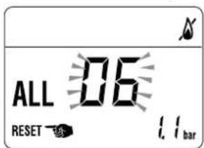
1 2 ALL 02 1.1 bar Fig. 4If you see alarm "06" (no flame detected) and "07" (safety thermostat intervention):
- press and hold the button ⬇R for more than 3 seconds and check whether normal operating conditions are restored.
text_image
ALL 06 RESET ↑ 1.1 bar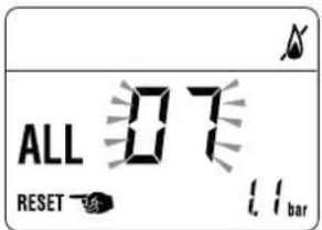
text_image
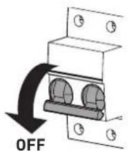
ALL 07 RESET 1.1 barIf this operation is not successful, ONLY ONE MORE ATTEMPT can be made, therefore:
- close the gas isolation valve
- set the main system switch to "OFF"
- contact the Qualified Technical Personnel.
text_image
OFF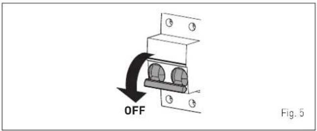
text_image
OFF Fig. 5
CAUTION
Should you see an alarm not described here, contact a qualified technical professional
1.6.1 Maintenance request
When it is time to perform maintenance on the boiler, the symbol shows on the display.
natural_image
Simple diagram with a dog silhouette and motion lines, no text or symbols presentContact the technical assistance service to organise the necessary work.
2 SHUTDOWN
2.1 Temporary shutdown
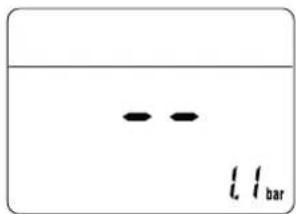
If the user wishes to interrupt boiler operation, press and hold the button OR for at least one second, once if in "WINTER mode"
or twice if in "SUMMER mode"
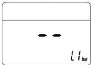
"--" will appear on the display.
text_image
l l bar
ELECTRICAL HAZARD
The boiler will still be powered.
If the user is away temporarily, for a weekend, short trip etc and if the outside temperature is at ZERO:
- press and hold the button 📍 once if in "WINTER mode" 🔊 or twice if in "SUMMER mode" 🔊 to put the boiler into stand-by
- set the main system switch to "OFF"
- close the gas valve.

text_image
OFF Fig. 6
CAUTION
If the outside temperature might fall below ZERO, since the appliance is equipped with an "antifreeze function"
- ONLY PUT THE BOILER INTO STAND-BY
- leave the main system switch set to "ON" (boiler is powered)
- leave the gas valve open.
2.2 Shutting down for long periods
If the boiler is to be left unused for a long period, the following operations need to be carried out:
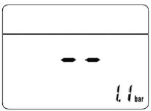
- press and hold the button ⏻R for at least 1 second, once if in "WINTER mode" 🔊 or twice if in "SUMMER mode" 🔊 to put the boiler into stand-by "-" will appear on the display
text_image
i, i_bar- set the main system switch to "OFF"
text_image
OFFFig. 7
- close the gas valve
- close the heating and domestic hot water isolation valves
- drain the heating and domestic hot water system if there is the risk of freezing.

CAUTION
Contact the Qualified Technical Personnel if the procedure described above cannot be easily carried out.
3 MAINTENANCE
3.1 Adjustments
For the appliance to operate correctly and efficiently it is recommended that the User calls upon the services of a Professionally Qualified Technician to carry out ANNUAL maintenance.

CAUTION
Maintenance interventions must ONLY be carried out by professionally qualified personnel who will follow the indications provided in the INSTALLATION AND MAINTENANCE MANUAL.
3.2 External cleaning

WARNING
- Should it be necessary to access the areas in the bottom part of the appliance, make sure that the system components and pipes are not hot (risk of burning).
- Before performing any maintenance, put on protective gloves.
3.2.1 Cleaning the cladding
When cleaning the cladding, use a cloth dampened with soap and water or alcohol for stubborn marks.

IT IS FORBIDDEN
to use abrasive products.
4 DISPOSAL
4.2.2 Brava Slim 25 BF ÷ Brava Slim 30 BF
At the end of their life span, the appliance and electrical and electronic devices coming from households or classifiable as household waste must be delivered to appropriate waste collection systems, in accordance with the law and with Directive 2012/19/EU. This product was designed and manufactured for minimising its impact on the environment and on human health, but it contains components that could be detrimental if managed improperly. The symbol (crossed-out wheelie bin) depicted here and also appearing on your appliance means that the appliance at the end of its life must be managed in accordance with the law and treated as electrical and electronic waste. Before delivering the appliance for its disposal, consult the applicable provisions of the laws in force in the country where the appliance is used and get information on the authorised waste disposal facilities by contacting the relevant local offices.


IT IS FORBIDDEN
dispose of the product with urban waste.
4.2.3 Brava Slim 40 BF
At the end of their life span, the appliance and electrical and electronic devices coming from professional facilities or classifiable as professional waste must be delivered to appropriate waste collection systems, in accordance with the law and with Directive 2012/19/EU. This product was designed and manufactured for minimising its impact on the environment and on human health, but it contains components that could be detrimental if managed improperly. The symbol (crossed-out wheelie bin) depicted here and also appearing on your appliance means that the appliance at the end of its life must be managed in accordance with the law and treated as electrical and electronic waste. Before delivering the appliance for its disposal, consult the applicable provisions of the laws in force in the country where the appliance is used and get information on the authorised waste disposal facilities by contacting the relevant local offices.


IT IS FORBIDDEN
dispose of the product with urban waste.
DESCRIPTION OF THE APPLIANCE
TABLE OF CONTENTS
5 DESCRIPTION OF THE APPLIANCE 54
5.1 Characteristics 54
5.2 Check and safety devices 54
5.3 Identification 54
5.4 Structure 55
5.4.1 Brava Slim 25 BF - Brava Slim 30 BF....55
5.4.2 Brava Slim 40 BF 56
5.5 Technical features 57
5.6 Main water circuit 58
5.7 Sensors....58
5.8 Expansion vessel....58
5.9 Circulation pump 58
5.10 Control panel 59
5.11 Wiring diagram 60
5 DESCRIPTION OF THE APPLIANCE
5.1 Characteristics
Brava Slim BF are last generation low temperature wall mounted boilers which Sime has produced for heating and domestic hot water production. The main design choices made by Sime for the Brava Slim BF boilers are:
- the atmospheric burner combined with a copper heat exchanger for heating and a rapid heat exchanger for DHW
- the sealed combustion chamber which can be classified "Type C" or "Type B" in relation to the room where the boiler is installed, depending on the smoke outlet configuration adopted during installation
- the command and control microprocessor electronic board provides efficient management of both heating and hot water production. It can also be connected to a remote control with an Open Therm protocol or to room thermostat and/or external sensor. If connected to an external sensor, the boiler temperature varies on the basis of the external temperature according to a selected optimal climatic curve providing significant energy and economic savings.
Other special features of the Brava Slim BF boilers are:
- the anti-freeze function which activates automatically if the temperature of the water inside the boiler falls below the threshold of the value set at parameter "PAR 10" and, if there is an external sensor, if the external temperature falls below the threshold of the value set at parameter "PAR 11"
- the anti-blocking function of the pump and diverter valve, this activates automatically every 24 hours if no request for heat has been made
- the chimney sweep function lasts 15 minutes and makes the job of the qualified technician easier when measuring the parameters and combustion efficiency and when checking gas pressure at the nozzles
- domestic hot water comfort function which allows the time necessary for the hot water to become available to be reduced and ensures that the temperature is stable
- screen display of the operating and self-diagnostic parameters with error code display when the fault occurs. This makes repair interventions easier and allows appliance operation to be restored correctly.
5.2 Check and safety devices
The Brava Slim BF boilers are equipped with the following check and safety devices:
- thermal safety sensor 100°C
- 3 bar relief valve
- heating water pressure transducer
- delivery sensor
- DHW sensor.

IT IS FORBIDDEN
To commission the appliance with safety devices which do not work or which have been tampered with.

WARNING
Safety device may only be replaced by professional qualified personnel using Sime original spare parts.
5.3 Identification
The Brava Slim BF boilers can be identified by means of:
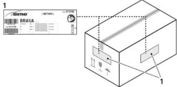
1 Packaging label: this is located on the outside of the packaging and provides a code, the serial number of the boiler and the bar code
2 Technical Data Plate: this is located inside the front panel of the boiler and provides the technical specification, appliance performance and any other information required by law.
text_image
Sime (BETA0) BRAVA 1 1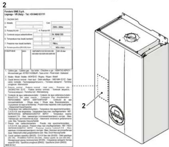
text_image
Fondora SIME S.p.A. Legnage (VR (kg)) - Tel. +0-0442 63111 1. CALIXA GAS 2. Metal 3. Capac 4. Capacitor 5. Capacitor 6. Capacitor 7. Capacitor max circuit board 8. Temperature max circuit board 9. Pressure max circuit board 10. Power output (IN 600V)... FIGURE 10. ISO: REP-BSP-EU/DC-DC-DC-DC-DC-DC-DC-DC-DC-DC-DC-DC-DC-DC-DC-DC-DC-DC-DC-DC-DC-DC-DC-DC-DC-DC-DC-DC-DC-DC-DC-DC-DC-DC-DC-DC-DC-DC-DC-DC-DC-DC-DC-DC-DC-DC-DC-DC-DC-DC-DC- 1. Cable gas - Cable gas - Gas boiler - CDHOSO gas - HENRYKLEPOT - MUNICOMATO GAS / KETES/ASTABETHAN TAACA outlet - Peral inlet - Ductorin 2. Motor - Model - MONTEC - Mihara - Mihari - Mihari 3. Caudal terminal - Heat input - Debit outlet - DEBT verification - 100/100A EYE - Debit cation nominal - Tymnoepower/microcarbics - Tumenees equipment - Temtrino imagingator - Winku.edu 4. Pressure control - Potency control - heat input - Potency control - URB/CEM/CEE - Potency terminal - Potency unit - Potency unit - Potency unit 5. Caudal terminal - URB/CEM/CEE - Potency terminal - Potency unit - Potency unit 6. Caudal terminal - URB/CEM/CEE - Potency terminal - Potency unit - Potency unit 7. Caudal terminal - URB/CEM/CEE - Potency terminal - Potency unit - Potency unit 8. Caudal terminal - URB/CEM/CEE - Potency terminal - Potency unit - Potency unit 9. Caudal terminal - URB/CEM/CEE - Potency terminal - Potency unit - Potency unit Temperature max circuit board - Temperature max circuit board - Temperature max circuit board - Temperature max circuit board - Temperature max circuit board - Temperature max circuit board - Temperature max circuit board - Temperature max circuit board - Temperature max circuit board - Temperature max circuit board - Temperature max circuit board - Temperature max circuit board - Temperature max circuit board - Temperature max circuit board - Temperature max circuit board - Temperature max circuit board - Temperature max circuit board - Temperature max circuit board - Temperature max circuit board - Temperature max circuit board - Temperature max circuit board- Temperature max circuit board- Temperature max circuit board- Temperature max circuit board- Temperature max circuit board- Temperature max circuit board- Temperature max circuit board- Temperature max circuit board- Temperature max circuit board- Temperature max circuit board- Temperature max circuit board- Temperature max circuit board- Temperature max circuit board- Temperature max circuit board- Temperature max circuit board- Temperature max circuit board- Temperature max circuit board- Temperature max circuit board- Temperature max circuit board- Temperature max circuit board- Temperature max circuit board, Temperature max circuit board, Temperature max circuit board, Temperature max circuit board, Temperature max circuit board, Temperature max circuit board, Temperature max circuit board, Temperature max circuit board, Temperature max circuit board, Temperature max circuit board, Temperature max circuit board, Temperature max circuit board, Temperature max circuit board, Temperature max circuit board, Temperature max circuit board, Temperature max circuit board, Temperature max circuit board, Temperature max circuit board, Temperature max circuit board, Temperature max circuit board, Temperature max circuit board, Temperature max circuit board, Temperature max circuit board, Temperature max circuit board, Temperature max circuit board, Temperature max circuit board, Temperature max circuit board, Temperature max circuit board, Temperature max circuit board, Temperature max circuit board, Temperature max circuit board, Temperature max circuit board, Temperature max circuit board, Temperature max circuit board, Temperature max circuit board, Temperature max circuit board, Temperature max circuit board, Temperature max circuit boards, Tambus/Chambe/Szichan (EN2D), D-X-M line (EN2D), Delt cap/plate (D-M), Tambus/Chambe/Szichan (EN2D), D-X-M line (EN2D), Delt cap/plate (D-M), Tambus/Chambe/Szichan (EN2D), D-X-M line (EN2D), Delt cap/plate (D-M), Tambus/Chambe/Szichan (EN2D), D-X-M line (EN2D), Delt cap/sat (EN2D), Tambus/Chambe/Szichan (EN2D), D-X-M line (EN2D), Delt cap/sat (EN2D), Tambus/Chambe/Szichan (EN2D), D-X-M line (EN2D), Delt cap/sat (EN2D), Tambus/Chambe/Szichan (EN2D), D-X-M line (EN2D),Fig. 8

CAUTION
Tampering with, removing or failing to display the identification plate or carrying out any other operation which does not allow safe identification of the product or which may hinder installation and maintenance operations.
5.4 Structure
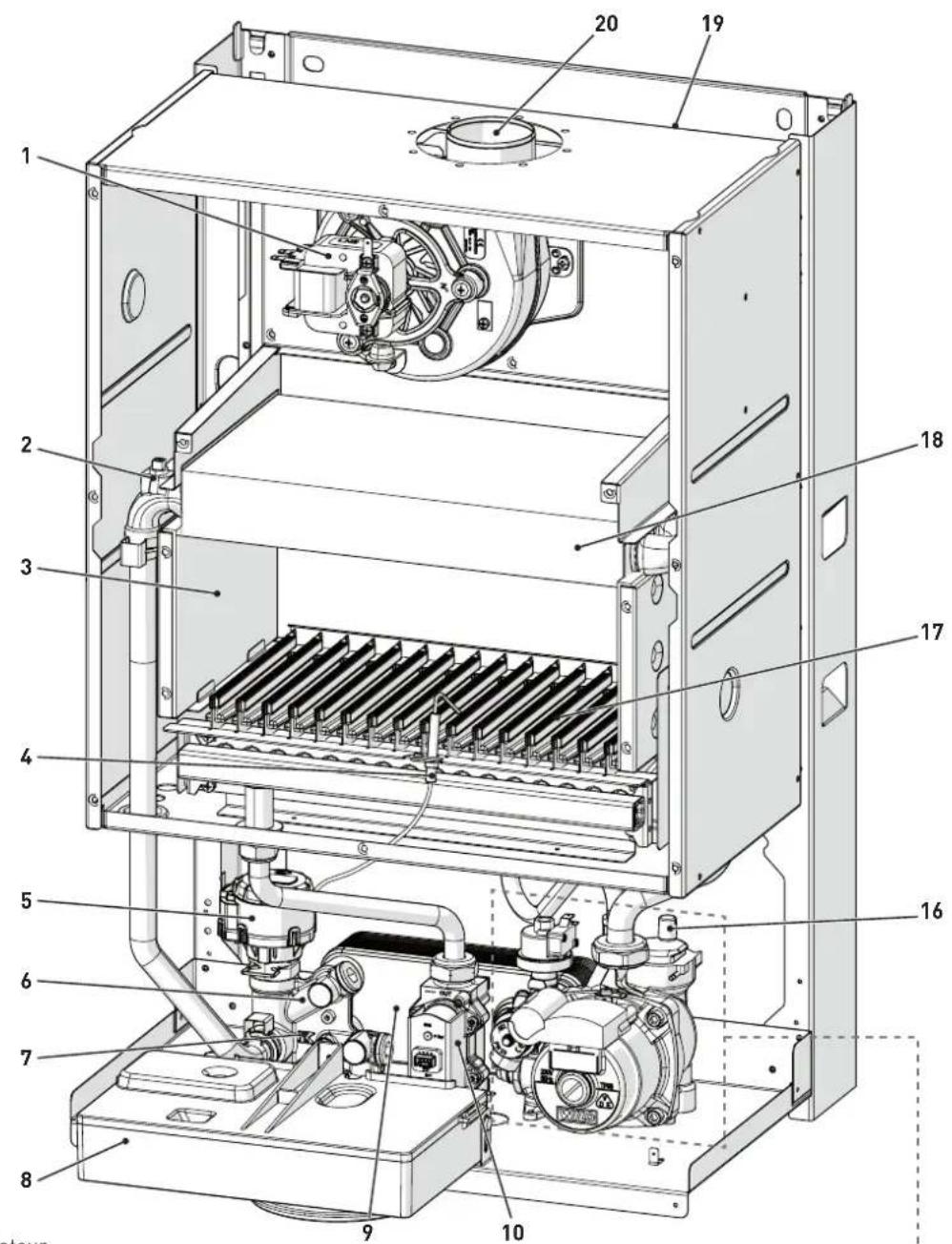
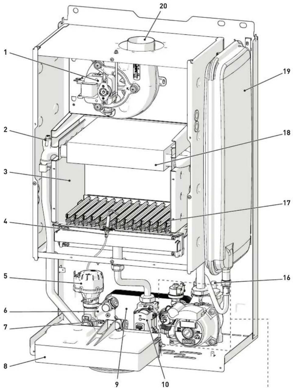
5.4.1 Brava Slim 25 BF - Brava Slim 30 BF
text_image
Technical diagram of an industrial machine with numbered components for identification1 Fan
2 Dual sensor (thermal safety/delivery)
3 Combustion chamber
4 Ignition/detection electrode
5 Diverter valve
6 System filling unit
7 Domestic hot water sensor
8 Control panel
9 Secondary heat exchanger
10 Gas valve
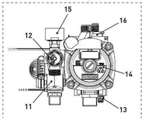
11 Domestic water filter and flow regulator
12 System relief valve
13 Boiler drain
14 System pump
15 Water pressure transducer
16 Automatic bleed valve
17 Burner
18 Primary heat exchanger
19 Expansion vessel
20 Smoke outlet
text_image
Technical diagram of a mechanical device with numbered components labeled 11 through 16.Fig. 9
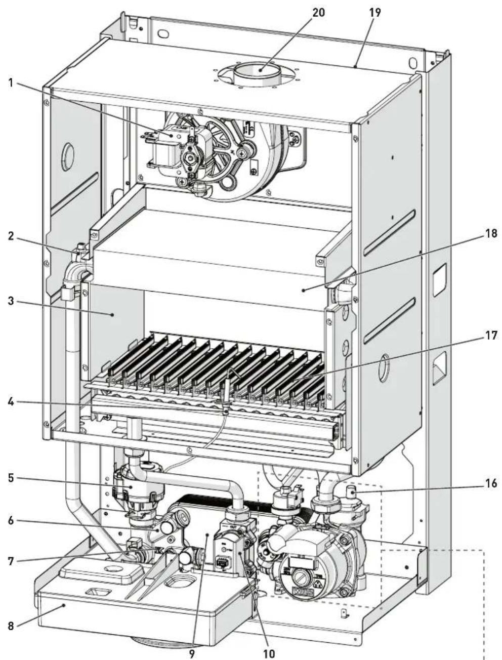
5.4.2 Brava Slim 40 BF
text_image
Technical diagram of an internal combustion chamber with numbered components for identification1 Fan
2 Dual sensor (thermal safety/delivery)
3 Combustion chamber
4 Ignition/detection electrode
5 Diverter valve
6 System filling unit
7 Domestic hot water sensor
8 Control panel
9 Secondary heat exchanger
10 Gas valve
11 Domestic water filter and flow regulator
12 System relief valve
13 Boiler drain
14 System pump
15 Water pressure transducer
16 Automatic bleed valve
17 Burner
18 Primary heat exchanger
19 Expansion vessel
20 Smoke outlet
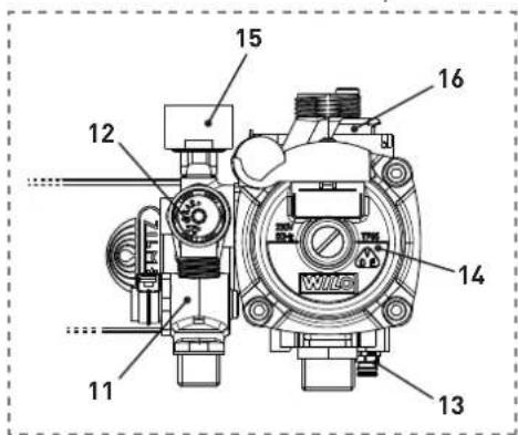
text_image
Technical diagram of a mechanical device with numbered components labeled 11 to 16.Fig. 10
5.5 Technical features
| DESCRIPTION | Brava Slim 25 BF Brava Slim 30 BF Brava Slim 40 BF | |||
| CERTIFICATIONS | ||||
| Country of intended installation DZ - TN | ||||
| Fuel G20 - G30/G31 | ||||
| PIN number 1312CP5935 | ||||
| Category II2H3+ | ||||
| Type | B22P - B32P - B52PC12 - C12X - C32 - C32X - C42 - C42X - C52 - C52XC62 - C62X - C82 - C82X - C92 | |||
| Class NOx | 3 [< 150 mg/kWh] | |||
| DHW rated useful heat output | kW | 23,7 | 28,1 | 37,3 |
| HEATING PERFORMANCE | ||||
| HEAT INPUT | ||||
| Nominal | kW | 25,5 | 30,0 | 40,0 |
| Minimum | kW | 9,2 | 10,8 | 13,5 |
| HEAT OUTPUT | ||||
| Nominal (80-60°C) | kW | 23,7 | 28,1 | 37,2 |
| Minimum (80-60°C) | kW | 7,8 | 9,2 | 11,3 |
| EFFICIENCY | ||||
| Max useful efficiency (80-60°C) | % | 93,0 | 93,7 | 93,0 |
| Min useful efficiency (80-60°C) | % | 84,8 | 85,2 | 83,6 |
| Useful efficiency at 30% of load (50-30°C) | % | 90,5 | 91,1 | 91,7 |
| Thermal efficiency (EEC 92/42) % | ★★★ | |||
| Losses after shutdown at 50°C | W | 71 | 75 | 88 |
| DOMESTIC HOT WATER PERFORMANCE | ||||
| Nominal heat input | kW | 25,5 | 30,0 | 40,0 |
| Minimum heat input | kW | 9,2 | 10,8 | 13,5 |
| D.H.W. flow rate Δt 30°C | l/min | 11,3 | 13,4 | 17,8 |
| Continuous D.H.W. flow rate (Δt 25°C/Δt 35°C) | l/min | 13,6 / 9,7 | 16,1 / 11,5 | 21,3 / 15,2 |
| Minimum D.H.W. flow rate | l/min | 2,2 | 2,2 | 2,2 |
| Max / Min Pressure | bar | 7 / 0,4 | 7 / 0,4 | 7 / 0,4 |
| kPa | 700 / 40 | 700 / 40 | 700 / 40 | |
| ELECTRICAL SPECIFICATIONS | ||||
| Power supply voltage | V | 230 | ||
| Frequency | Hz | 50 | ||
| Absorbed electrical power | W | 112 | 113 | 136 |
| Electrical protection degree | IP | X5D | ||
| COMBUSTION DATA | ||||
| Smoke temperature at Max/Min flow (80-60°C) | °C | 142,5 / 96,4 | 151,9 / 100,8 | 147/91 |
| Smoke flow Max/Min | g/s | 17 / 16 | 19 /19 | 23/26 |
| CO2 at Max/Min (G20) flow rate with separate chimneys | % | 6,7 / 2,1 | 7,1 / 2,3 | 7,4/2,1 |
| CO2 at Max/Min (G31) flow rate with separate chimneys | % | 7,7 / 2,6 | 7,8 / 2,7 | 8,1/2,6 |
| NOZZLES - GAS | ||||
| Number of nozzles | No. | 11 | 13 | 16 |
| Nozzle diameter (G20) | mm | 1,30 | 1,30 | 1,40 |
| Nozzle diameter (G30/G31) | mm | 0,80 | 0,78 | 0,81 |
| Gas consumption at Max/Min flow rate (G20) | m3/h | 2,70 / 0,97 | 3,17 / 1,14 | 4,25/1,40 |
| Gas consumption at Max/Min flow rate (G30) | kg/h | 2,01 / 0,72 | 2,36 / 0,85 | 3,15/1,06 |
| Gas consumption at Max/Min flow rate (G31) | kg/h | 1,98 / 0,71 | 2,33 / 0,84 | 3,10/1,04 |
| Gas supply pressure (G20/G30/G31) | mbar | 20 / 28-30 / 37 | ||
| kPa | 2 / 2,8-3 / 3,7 | |||
| TEMPERATURE - PRESSURE | ||||
| Max operating temperature | °C | 85 | 85 | 85 |
| Heating adjustment range | °C | 20 ÷ 80 | 20 ÷ 80 | 20 ÷ 80 |
| Domestic hot water adjustment range | °C | 10 - 60 | 10 - 60 | 10 - 60 |
| Max operating pressure | bar | 3 | 3 | 3 |
| kPa | 300 | 300 | 300 | |
| Water content in boiler | l | 3,05 | 3,65 | 4,90 |
Lower Heat Output (Hi)
G20 Hi. 9.45 kW/m³ (15°C, 1013 mbar) - G30 Hi. 12.68 kW/kg (15°C, 1013 mbar) - G31 Hi. 12.87 kW/kg (15°C, 1013 mbar)
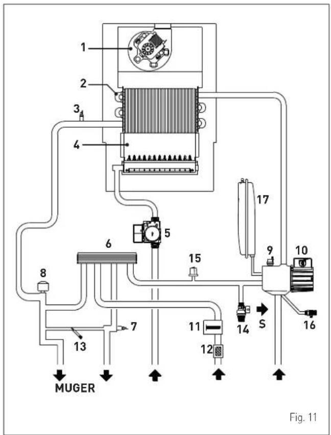
5.6 Main water circuit
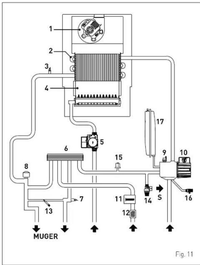
text_image
1 2 3 4 5 6 7 8 MUGER 11 12 13 14 S 15 16 9 10 17 Fig. 11KEY:
M System delivery
R System return
U Domestic hot water outlet
E Domesti hot water inlet
S Safety valve outlet
G Gas supply
1 Fan
2 Heat exchanger (mono-thermal)
3 Dual sensor (thermal safety/delivery)
4 Combustion chamber
5 Gas valve
6 Domestic hot water heat exchanger
7 Domestic hot water sensor
8 Diverter valve
9 Automatic bleed valve
10 Pump
11 Domestic hot water flow meter
12 Domestic hot water filter
13 System filling
14 System relief valve
15 Water pressure transducer
16 Boiler drain
17 System expansion vessel
5.7 Sensors
The sensors installed have the following characteristics:
- Dual sensor (thermal safety/output) NTC R25°C; 10kΩ B25°-85°C: 3435
- domestic hot water sensor NTC R25°C; 10kΩ B25°-85°C; 3435
- External temperature sensor NTC R25°C; 10kΩ B25°-85°C: 3435
Correspondence of Temperature Detected/Resistance
Examples of reading:
TR = 75^ R = 1925
TR = 80^ R = 1669.
| TR | 0°C | 1°C | 2°C | 3°C | 4°C | 5°C | 6°C | 7°C | 8°C | 9°C | ||||
| 0°C | 27279 | 26135 | 25044 | 24004 | 23014 | 22069 | 21168 | 20309 | 19489 | 18706 | Resistance R (Ω) | |||
| 10°C | 17959 | 17245 | 16563 | 15912 | 15289 | 14694 | 14126 | 13582 | 13062 | 12565 | ||||
| 20°C | 12090 | 11634 | 11199 | 10781 | 10382 | 9999 | 9633 | 9281 | 8945 | 8622 | ||||
| 30°C | 8313 | 8016 | 7731 | 7458 | 7196 | 6944 | 6702 | 6470 | 6247 | 6033 | ||||
| 40°C | 5828 | 5630 | 5440 | 5258 | 5082 | 4913 | 4751 | 4595 | 4444 | 4300 | ||||
| 50°C | 4161 | 4026 | 3897 | 3773 | 3653 | 3538 | 3426 | 3319 | 3216 | 3116 | ||||
| 60°C | 3021 | 2928 | 2839 | 2753 | 2669 | 2589 | 2512 | 2437 | 2365 | 2296 | ||||
| 70°C | 2229 | 2164 | 2101 | 2040 | 1982 | 1925 | 1870 | 1817 | 1766 | 1717 | ||||
| 80°C | 1669 | 1622 | 1577 | 1534 | 1491 | 1451 | 1411 | 1373 | 1336 | 1300 | ||||
| 90°C | 1266 | 1232 | 1199 | 1168 | 1137 | 1108 | 1079 | 1051 | 1024 | 998 | ||||
| 100°C | 973 |
5.8 Expansion vessel
The expansion vessel installed on the boilers has the following characteristics:
| Description U/M | Brava Slim BF | |||
| 25 | 30 | 40 | ||
| Total capacity | l | 8,0 | 9,0 | |
| Prefilling pressure | kPa | 100 | ||
| bar | 1,0 | |||
| Useful capacity | l | 4,0 | 5,0 | |
| Maximum system content (*) | l | 109 | 124 | |
(*) Conditions of:
Average operating temperature 70°C (with high temperature system 80/60°C)
Start temperature at system filling 10^ C.

CAUTION
- For systems with water content exceeding the maximum system content (as indicated in the table) an additional expansion vessel must be prearranged.
- The difference in height between the relief valve and the highest point of the system cannot exceed 6 metres. If the difference is greater than 6 metres, increase the prefilling pressure of the expansion vessel and the system when cold by 0.1 bar for each meter increase.
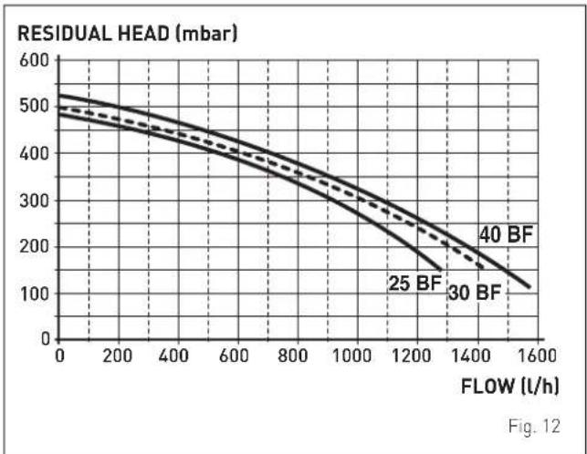
5.9 Circulation pump
The flow-head performance curve available for the heating system is shown in the graph below.
line
| FLOW (l/h) | RESIDUAL HEAD (mbar) | | ---------- | --------------------- | | 0 | 500 | | 200 | 480 | | 400 | 450 | | 600 | 420 | | 800 | 380 | | 1000 | 320 | | 1200 | 250 | | 1400 | 180 | | 1600 | 120 |5.10 Control panel
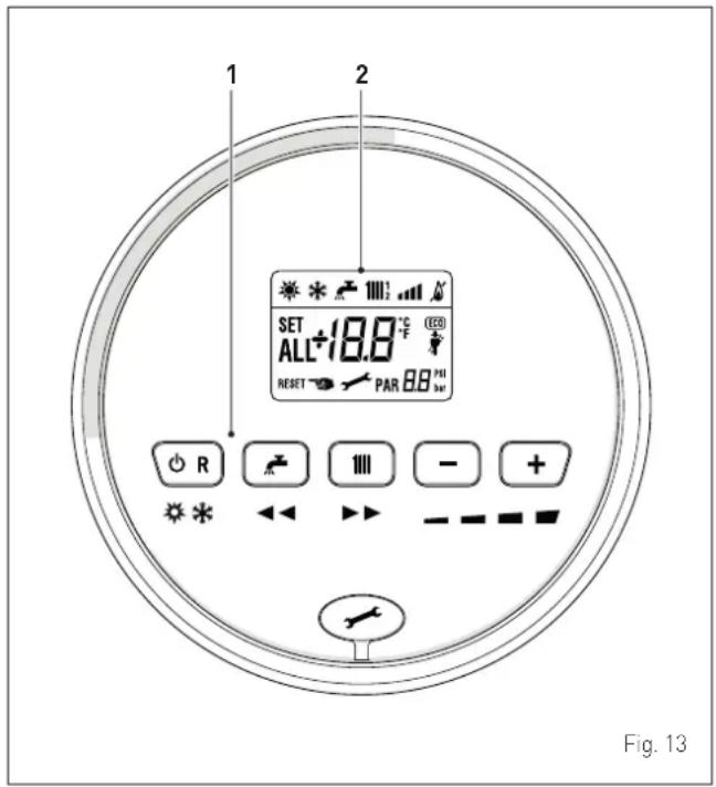
text_image
1 2 SET ALL+18.8 °C RESET PAR 88° R 111 - + * ← - - - - - Fig. 131 FUNCTIONAL BUTTONS
OR If pressed once or more than once for at least 1 second during normal operation, this button allows the user to change the boiler operating mode in a cyclical sequence (Stand-by - Summer - Winter). If the boiler is experiencing a fault which can be reset, it allows boiler operation to be unblocked.
During normal operation, pressing the button displays the domestic hot water set point which can be between 10 and 60°C. In "parameter setting", the user can scroll through the parameter index (decreasing) by pressing this button.
During normal operation, pressing the button displays the heating set point which can be between 20 and 80°C. In "parameter setting", the user can scroll through the parameter index (increasing) by pressing this button.
— During normal operation, pressing this button allows the user to reduce the heating or DHW set point on the basis of the selection made previously. If there is a Remote Control (Open Therm), after having selected the heating button, the user can modify the incline of the climatic curve (decreasing it) by pressing the button (-). In "parameter setting/display", the user can modify the parameter setting or value (decreasing) by pressing this button.
+ During normal operation, pressing this button allows the user to increase the heating or DHW set point on the basis of the selection made previously. If there is a Remote Control (Open Therm), after having selected the heating button, the user can modify the incline of the climatic curve (increasing it) by pressing the button (+). In "parameter setting/display", the user can modify the parameter setting or value (increasing) by pressing this button.
Programming connector cover plug.
NOTE: pressing any one of these buttons for more than 30 seconds generates a fault on the display without preventing boiler operation. The warning disappears when normal conditions are restored.
2 DISPLAY

"SUMMER". This symbol appears when the boiler is operating in "Summer" mode or if only the domestic hot water mode is enabled via the remote control. If the symbols and are flashing, this indicates that the chimney sweep function is active.

"WINTER". This symbol appears when the boiler is operating in "Winter" mode or if both the domestic hot water and heating modes are enabled via the remote control. With the remote control, if no operating modes have been enabled both symbols and will be off.

"RESET REQUIRED". The message indicates that after having repaired the fault, normal boiler operation can be restored by pressing the button OR.

"DOMESTIC HOT WATER". This symbol is present during a DHW request or during the "chimney sweep function" It flashes during the selection of the domestic hot water set point.

"HEATING". This symbol lights up during heating operation or during the "chimney sweep function It flashes during the selection of the heating set point.

"BLOCK" DUE TO NO FLAME.

"FLAME PRESENCE".

"POWER LEVEL". This indicates the power level at which the boiler is operating.

"PARAMETER". This indicates that the user may be in parameter setting/display, or "info" or "counter", or in "activated alarms" (history).

"ALARM". This indicates that a fault has occurred. The number specifies the cause which generated the alarm.

"CHIMNEY SWEEP". This indicates that the "chimney sweep function" has been activated.

"ECO", ALTERNATIVE ENERGY SOURCES. Where active, it indicates that there is a solar system available.

"MAINTENANCE REQUEST". If active, it shows it is time to perform maintenance on the boiler.
5.11 Wiring diagram
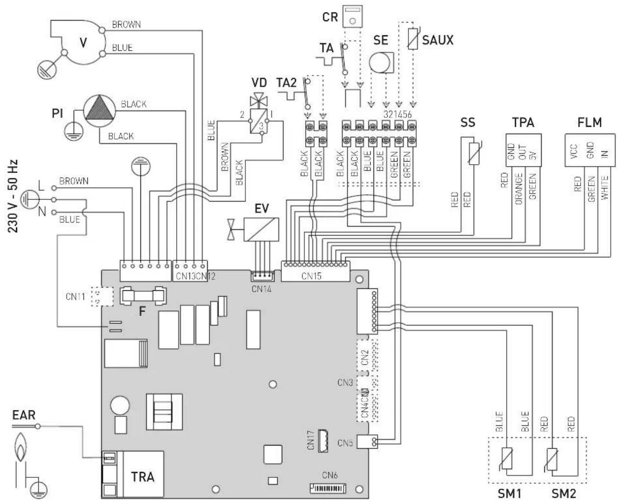
text_image
230 V - 50 Hz BROWN BLUE PI BLACK BLACK L N BROWN BLUE CN11 F EAR TRA CR TA VD TA2 2 3 EV CN13CN12 CN14 CN15 CN3 CN2 CN4CN CN5 CN6 CR SAUX 321456 SS TPA FLM RED RED RED OUT 3V GND GND IN GREEN GREEN RED GREEN WHITE BLUE BLUE RED SM1 SM2L Line
N Neutral
F Fuse (3.15AT - 250V)
TRA Ignition transformer
PI System pump
V Fan
EAR Ignition / Detection electrode
EV Gas solenoid valve
SS Domestic hot water sensor
SM1-2 Dual sensor (thermal safety/delivery)
FLM Flow meter
VD Diverter valve
TPA Pressure transducer
TA-TA2 Air thermostat
SE External sensor
SAUX Auxiliary sensor
CR Remote control (instead of air thermostat)
To connect the "Air Thermostat" or, alternatively the "Remote Control", remove the bridge between terminals 5-6.
Fig. 14

CAUTION
Users must:
- Use an omnipolar cut-off switch, disconnect switch in compliance with EN Standards which ensures complete cut-off in overvoltage category III conditions (i.e. where there is at least 3 mm between the open contacts).
- Respect the connections L (Live) - N (Neutral).
- Ensure that the special power cable is only replaced with a cable ordered as a spare part and connected by professionally qualified personnel.

CAUTION
Users must:
- Connect the earth wire to an effective earthing system. The manufacturer is not responsible for any damage caused by failure to earth the appliance or failure to observe the information provided in the wiring diagrams.

IT IS FORBIDDEN
To use water pipes for earthing the appliance.
INSTALLATION AND SERVICING INSTRUCTIONS
TABLE OF CONTENTS
6 INSTALLATION 62
6.1 Receiving the product 62
6.2 Dimensions and weight....62
6.3 Handling....62
6.4 Installation room 62
6.5 New installation or installation of a replacement appliance 63
6.6 Cleaning the system 63
6.7 Water system treatment 63
6.8 Boiler installation 63
6.9 Plumbing connections....64 6.9.1 Plumbing accessories (optional)....64
6.10 Gas supply 64
6.11 Smoke outlet and combustion air inlet 65
6.11.1 Coaxial duct (∅ 60/100mm and ∅ 80/125mm)66
6.11.2 Separate ducts (Ø 80mm)....66
6.12 Electrical connections....68
6.12.1 External temperature sensor.... 69
6.12.2 Chrono-thermostat or Air Thermostat .... 69
6.12.3 EXAMPLE of use of the command/control device on some types of heating systems. . 69
6.13 Refilling or emptying....70
6.13.1 REFILL operations 70
6.13.2 EMPTYING operations 71
7 COMMISSIONING 72
7.1 Preliminary operations....72
7.2 Before commissioning 72
7.3 Parameter setting and display....72
7.4 List of parameters....73
7.5 Display of operating data and counters....75
7.6 Checks and adjustments 76
7.6.1 Chimney sweeper function.... 76
7.6.2 Adjusting gas pressure at the nozzles.....77
7.7 Gas conversion....78
7.7.1 Preliminary operations.... 78
7.8 Automatic calibration procedure ..... 79
7.9 Domestic hot water comfort function (preheating) ... 81
8 MAINTENANCE 82
8.1 Adjustments....82
8.2 External cleaning....82
8.2.1 Cleaning the cladding.... 82
8.3 Cleaning the inside of the appliance 82
8.3.1 Cleaning the heat exchanger 82
8.3.2 Cleaning the burner 83
8.3.3 Checking the ignition/detection electrode . 83
8.3.4 Final operations 83
8.4 Checks 83
8.4.1 Checking the smoke duct.... 83
8.4.2 Checking the expansion vessel pressure .. 83
8.5 Unscheduled maintenance....84
8.6 Malfunction codes and possible solutions ..... 84
8.6.1 Maintenance request 85

CAUTION
The appliance must only be installed by the Sime Technical Service or by qualified professionals who MUST wear suitable protective safety equipment.
6.1 Receiving the product
Brava Slim BF appliances are delivered in a single unit protected by cardboard packaging.
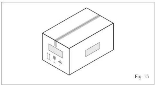
natural_image
Isometric line drawing of a cardboard box with internal components and label 'Fig. 15' (no text or symbols on the diagram itself)The plastic bag found inside the packaging contains the following:
- Installation, use and maintenance manual
- Paper template for boiler installation
- Certificate of warranty
- Hydrostatic test certificate
- System booklet
- Bag with expansion plugs

IT IS FORBIDDEN
To leave packaging material around or near children since it could be dangerous. Dispose of it as prescribed by legislation in force.
6.2 Dimensions and weight
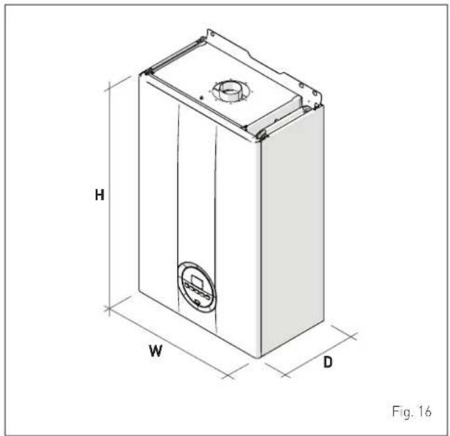
natural_image
Technical line drawing of a rectangular device with labeled dimensions H, W, D and a central circular feature (no text or symbols beyond labels)| Description | Brava Slim BF | ||
| 25 30 40 | |||
| W (mm) 400 450 450 | |||
| D (mm) 250 250 340 | |||
| H (mm) 700 700 700 | |||
| Weight (kg) 29 31,5 36 | |||
6.3 Handling
Once the packaging has been removed, the appliance is to be handled manually, tilting it slightly, lifting it and applying pressure in the points indicated in the figure.
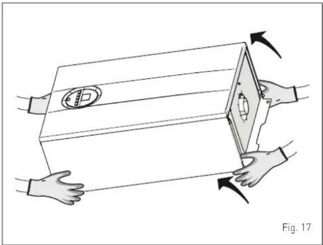
natural_image
Illustration of hands holding a box with a shield emblem, showing mechanical components and directional arrows (no text or symbols)
IT IS FORBIDDEN
To grip the appliance casing. Hold the "solid" parts of the appliance such as the base and structural frame.

WARNING
Use suitable tools and accident protection when removing the packaging and when handling the appliance. Observe the maximum weight that can be lifted per person.
6.4 Installation room
The room where the appliance is to be installed must comply with the Technical Regulations and Legislation in force. It must be equipped with suitably sized ventilation openings when the installation is a "TYPE B" installation.
The minimum temperature of the installation room must NOT be lower than -5 °C.

CAUTION
- Before assembling the appliance, the installer MUST make sure that the wall supports the weight.
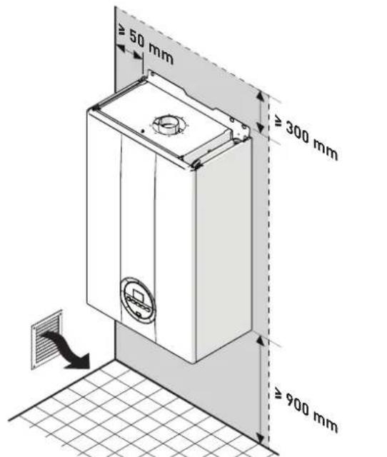
- Remember to consider the space needed in order to access the safety/adjustment devices and to carry out maintenance interventions (see Fig. 18).
APPROXIMATE MINIMUM DISTANCES
text_image
≥ 50 mm ≥ 300 mm ≥ 900 mmFig. 18
6.5 New installation or installation of a replacement appliance
When Brava Slim BF boilers are installed on old systems or systems requiring updating, it is recommended the installer checks that:
- the connecting flue pipe is suitable for the combustion temperature of the appliance, calculated and manufactured in compliance with Standards, that it is as straight as possible, air tight, isolated, with no obstructions or restriction and that it has appropriate condensate collection and evacuation systems
- the electrical system has been manufactured in compliance with specific Standards and by professionally qualified personnel
- the fuel delivery line and the tank (LPG) comply fully with specific Standards
- the expansion vessel ensures total absorption of the fluid dilation in the system
- the pump flow-head performance is sufficient for the system characteristics
- the system is clean, free of any sludge, deposits, de aerated and air tight. For system cleaning, please refer to the relevant paragraph.

CAUTION
The manufacturer declines all liability for any damage caused by an incorrect implementation of the smoke outlet or for an excessive use of additives.
6.6 Cleaning the system
Before installing the appliance on a newly constructed system or replacing a heat generator on an existing system, it is important that the system is thoroughly cleaned to remove sludge, slag, dirt, residue etc.
Before removing an old heat generator from an existing system, it is recommended that the user:
- puts a descaling additive into the water system
- allows the system to work with the generator active for a few days
- drains the dirty water from the system and flushes the system with clean water once or more than once.
If the old generator has already been removed or is not available, replace it with a pump to circulate water in the system and then proceed as described above.
Once cleaning operations have been carried out and before installing the new appliance, it is recommended that a fluid is added to the water system to protect it from corrosion and deposits.

CAUTION
- For further information on the type of additive and usage, please contact the appliance manufacturer.
- Please remember that you MUST install a Y filter (not supplied with the appliance) on the heating system return (R).
6.7 Water system treatment
When filling and restoring the system it is good practice to use water with:
- aspect: clear if possible
- pH: 6÷8
- hardness: < 25°f.
If the water characteristics are different from those indicated, it is recommended that a safety filter is used on the water delivery pipe to retain impurities, and a chemical treatment system to protect against possible deposits and corrosion which could affect boiler operation.
If the systems are only low temperature systems, it is recommended that a product is used to prevent the development of bacteria.
In any case, please refer to and comply with the legislation and specific technical standards in force in the country where the appliance will be used.
6.8 Boiler installation
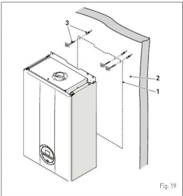
Brava Slim BF boilers leave the factory with a paper template for installation onto a solid wall.
For installation:
- position the paper template (1) on the wall (2) where the boiler is to be mounted
- make the holes and insert the expansion plugs (3)
- hook the boiler onto the plugs.
text_image
Fig. 19 1 2 3
CAUTION
The height of the boiler is to be such that disassembly and maintenance interventions are facilitated.
6.9 Plumbing connections
The plumbing connections have the following characteristics and dimensions.
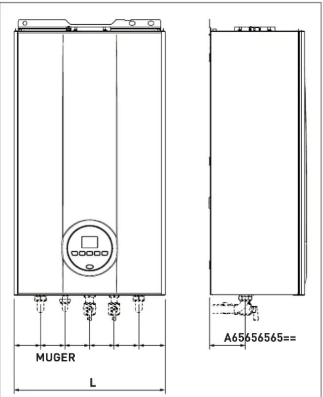
Fig. 20
| Description | Brava Slim BF | ||
| 25 30 40 | |||
| M - System delivery ∅ 3/4" G | |||
| R - System return ∅ 3/4" G | |||
| U - Domestic hot water output ∅ 1/2" G | |||
| E - Domestic hot water inlet ∅ 1/2" G | |||
| G - Gas supply | ∅ 3/4" G | ||
| A (mm) | 95 | 180 | |
| W (mm) | 400 | 450 | |
| Description | Brava Slim BF | ||
| 25 30 40 | |||
| M - System delivery ∅ 3/4" G | |||
| R - System return ∅ 3/4" G | |||
| U - Domestic hot water output ∅ 1/2" G | 1/2" G | ||
| E - Domestic hot water inlet ∅ 1/2" G | |||
| G - Gas supply | ∅ 3/4" G | ||
| A (mm) | 95 | 180 | |
| W (mm) | 400 | 450 | |
6.9.1 Plumbing accessories (optional)
To facilitate plumbing and gas connections to the systems, the accessories as shown in the table below are available and are to be ordered separately from the boiler.
| DESCRIPTION | CODE |
| Installation plate (25-30 kW) 8075441 | |
| Installation plate (40 kW) | 8075438 |
| Curve kit | 8075418 |
| Curve and valve kit with connections from DIN to SIME | 8075443 |
| Cocks kit | 8091806 |
| Valve kit with connections from DIN to SIME | 8075442 |
| Wall mount replacement kit for other makers | 8093900 |
| Solar kit for instant combination boilers | 8105101 |
| Fitting protection Kit (25 kW) | 8094530 |
| Fitting protection Kit (30 kW) | 8094531 |
| Polyphosphate dosing kit | 8101700 |
| Dosing recharge kit | 8101710 |
NOTE: kit instructions are supplied with the accessory itself or are to be found on the packaging.
6.10 Gas supply
Brava Slim BF boilers leave the factory specifically prearranged for G20 gas or G30/G31. The G20 models can be converted to function with G30/G31 using the "specific nozzle kit" (optional) provided by Sime on request separately from the boiler.
If changing the type of gas to be used, carry out the entire "GAS CONVERSION" phase of the appliance.
The boiler must be connected to the gas mains in full compliance with the installation standards in force in the country where the appliance will be used.
Before connecting the boiler to the gas mains, the user must ensure that:
- the type of gas is correct for the appliance
- the pipes are clean
- the gas supply pipe is the same dimension as or greater than that of the boiler fitting (G3/4") and with a load loss less than or equal to that contemplated between the gas mains and the boiler.

WARNING
Once installation has been completed, check that the joints are air tight as indicated in the installation Standards.

CAUTION
It is recommended that the gas line has a suitable filter.
6.11 Smoke outlet and combustion air inlet
Brava Slim BF boilers must be equipped with appropriate smoke flue ducts and combustion air inlet ducts. These ducts are considered an integral part of the boiler and are provided by Sime as an accessory kit, to be ordered separately from the appliance on the basis of the type permitted and the system requirements.
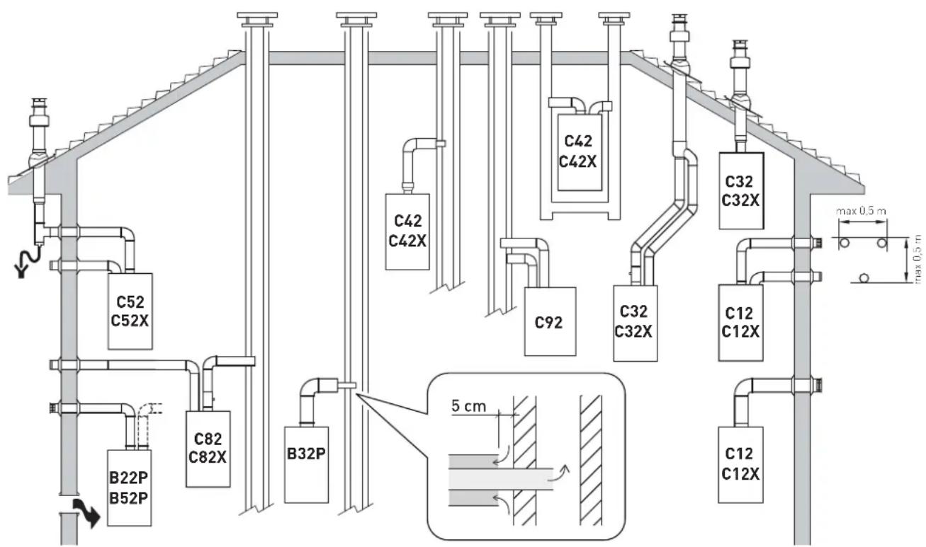
Permitted outlets
text_image
C52 C52X C82 C82X B22P B52P B32P C42 C42X C92 C42 C32 C32X C12 C12X C12 C12X max 0.5 m max 0.5 m 5 cmB22P-B52-B52P
Combustion air inlet into the atmosphere and smoke outlet to open air.
NOTE: opening for combustion air (6 cm ^2 x kW).
B32P
Combustion air inlet into the atmosphere and smoke outlet into single flue.
NOTE: opening for combustion air (15 cm ^2 x kW).
C12-C12X
Concentric wall smoke outlet The pipes can start from the boiler but the outlets must be concentric or close together (no more than 50 cm) to be subject to similar wind conditions.
C32-C32X
Concentric roof outlet Outlet as C12X.
C42-C42X
Outlet and inlet in shared or separate flue pipes but subjected to similar wind conditions.
C52-C52X
Separate wall or roof inlet and outlet in different pressure areas.
NOTE: the inlet and outlet must never be positioned on opposing walls.
C82-C82X
Outlet in single or shared flue or with inlet on wall.
C92
Separate outlet and inlet in shared flue pipe.
P: smoke outlet system designed to operate with positive pressure.
X: appliances and corresponding smoke outlet which meet German air-tightness requirements.
Fig. 21

WARNINGS
- The smoke flue and the connection to the flue pipe must be in compliance with the national and local standards and legislation in force in the country where the appliance will be used.
- The use of rigid ducts which are resistant to temperature, condensate, mechanical stress and are air-tight is compulsory.
- Outlet ducts which are not isolated are a risk of danger.
6.11.1 Coaxial duct ( 60/100mm and 80/125mm)
Coaxial accessories
| Description | Code | |
| ∅ 60/100 mm | ∅ 80/125 mm | |
| Coaxial duct kit 8084813 8084830 | ||
| Extension W. 1000 mm 8096103 8096130 | ||
| Extension W. 500 mm 8096102 - | ||
| Vertical extension W. 200 mm with smoke analysis take-off point | 8086908 - | |
| Adapter for ∅ 80/125 mm - 8093120 | ||
| Additional 90° curve 8095801 8095820 | ||
| Additional 45° curve 8095900 8095920 | ||
| Tile with joint 8091300 8091300 | ||
| Roof outlet terminal W. 1284 mm 8091200 | 8091200 | |
| Vertical condensation recovery W. 200 mm | 8092803 8092803 | |
Load loss - Equivalent lengths
| Model | Leq (linear metres) | |
| 60/100 mm | 80/125 mm | |
| 90° curve 1 1 | ||
| 45° curve 0,5 0,8 | ||
Minimum-Maximum Lengths
| Model | Duct Length ∅ 60/100 Duct Length ∅ 80/125 | |||||||
| W Horizontal (m) | H Vertical (m) | W Horizontal (m) | H Vertical (m) | |||||
| Min. | Max. | Min. | Max. | Min. | Max. | Min. | Max. | |
| Brava Slim 25 BF | - | 3,5 | 1,3 (*) | 5 | 3,5 | 6 | 4 | 7 |
| Brava Slim 30 BF | - | 3,0 | 1,3 (*) | 5 | 3 | 6 | 4 | 7 |
| Brava Slim 40 BF | - | 3,0 | 1,3 (*) | 5 | 3 | 6 | 4 | 7 |

CAUTION
(*) Vertical condensate recovery MUST be introduced for vertical ducts (Type C32) or vertical sections of the duct (Type C42) longer than 1.3m.
Diaphragms for coaxial ducts
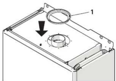
Boilers leave the factory equipped with a diaphragm (1) with the following characteristics:
- Brava Slim 25 BF: diaphragm ∅ 79 mm
- Brava Slim 30 BF: diaphragm ∅ 81 mm
- Brava Slim 40 BF: diaphragm ∅ 87,5 mm.
text_image
Technical diagram of a mechanical component with labeled parts and directional arrow indicating motion or forceFig. 22
When the outlets are Type C12 or C42 the diaphragm is to be removed or kept following the indications below:
| Model | Diaphragm | for duct L |
| Brava Slim 25 BF | YES(leave mounted) | < 1 m |
| Brava Slim 30 BF | ||
| Brava Slim 40 BF | ||
| Brava Slim 25 BF | NO(remove it) | > 1 m |
| Brava Slim 30 BF | ||
| Brava Slim 40 BF |
When the outlet is Type C32 (vertically straight without any curves), the presence of the diaphragm modifies the maximum length of the duct as shown below:
| Model | Diaphragm | Max L (m) |
| Brava Slim 25 BF | YES | 2,5 |
| Brava Slim 25 BF | NO | 5 |
| Brava Slim 30 BF | YES | 2,5 |
| Brava Slim 30 BF | NO | 5 |
| Brava Slim 40 BF | YES | 2,5 |
| Brava Slim 40 BF | NO | 5 |
6.11.2 Separate ducts ( 80mm)
Constructing outlets for separate ducts indicates the use of the "air-flue split pipe system". This is to be ordered separately from the boiler and when connected to the other accessories, from those listed in the table below, completes the smoke-outlet/combustion air inlet assembly.
The total maximum length, obtained by adding the length of the outlet and inlet pipes, is determined by the load loss of the individual accessories and must not be greater than 9 mm H2O for Brava Slim 25 BF, 9.5 mm H2O for Brava Slim 30 BF and 15 mm H2O for Brava Slim 40 BF.
Separate accessories
| Description | Code |
| Diameter ∅ 80 (mm) | |
| Air-flue split pipe system (with take-off point) + Diaphragm | 8093020 |
| 90° curve M-F (6 pieces) | 8077410 |
| 90° curve M-F (with take-off point) | 8077407 |
| 90° curve M-F (insulated) | 8077408 |
| Extension W. 1000 mm (6 pieces) | 8077309 |
| Extension W. 1000 mm (insulated) | 8077306 |
| Extension W. 500 mm (6 pieces) | 8077308 |
| Extension W. 135 mm (with take-off point) | 8077304 |
| Wall outlet terminal | 8089501 |
| Internal and external ring nut kit | 8091500 |
| Inlet terminal 8089500 | |
| 45° curve M-F (6 pieces) | 8077411 |
| Condensate recovery W. 135 mm | 8092800 |
| Manifold | 8091400 |
| Tile with joint | 8091300 |
| Roof outlet terminal W. 1390 mm | 8091201 |
| Condensate recovery Tee | 8093300 |
| Inlet/outlet fitting ∅ 80/125 mm | 8091401 |
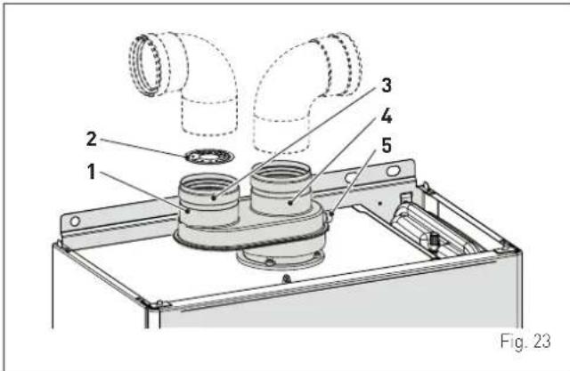
Split pipe system
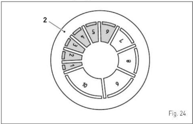
The split pipe system is supplied with the combustion air inlet diaphragm which is to be mounted, after the sections have been eliminated according to the total load loss which is calculated by summing the load losses of the inlet ducts to those of the outlet ducts.
text_image
1 2 3 4 5 Fig. 23KEY:
1 Split pipe system with take-off point
2 Inlet diaphragm
3 Air inlet
4 Smoke outlet
5 Take-off point for smoke analysis
Load loss accessory ∅ 80 mm
| Descrip-tion | Code | Load loss (mm H2O) | |||||
| Brava Slim 25 BF | Brava Slim 30 BF | Brava Slim 40 BF | |||||
| Inlet | Out- let | Inlet | Out- let | Inlet | Out- let | ||
| 90° curve MF | 8077410 | 0,35 0,40 | 0,45 0,5 | 0 0,70 1,50 | |||
| 45° curve MF | 8077411 | 0,30 0,35 | 0,40 0,45 | 0,60 1,00 | |||
| Horizontal extension W. 1000 mm | 8077309 | 0,20 0,30 | 0,25 0,35 | 0,40 0,65 | |||
| Vertical extension W. 1000 mm | 8077309 | 0,20 0,10 | 0,25 0,15 | 0,30 0,30 | |||
| Wall terminal | 8089501 | 0,15 0,50 | 0,20 0,8 | 0,25 2,00 | |||
| Condensate recovery Tee | 8093300 | 0,80 - 1,00 - 2,20 | |||||
| Roof outlet terminal (*) | 8091200 | 1,60 0,10 | 2,00 0,20 | 4,00 0,40 | |||
(*) The losses of the roof outlet terminal at inlet include the manifold code 8091400.
NOTE: for the boiler to operate correctly it is necessary that a minimum distance of 0.50 m of the duct is respected with a 90° inlet curve.
Example: calculation of the load loss of a Brava Slim 25 BF boiler.
| Accessories ∅ 80 mm | Code | Quan- tity | Load loss (mm H2O) | ||
| Inlet Out | tlet Total | ||||
| Extension W. 1000 mm (horizontal) | 8077309 | 7 7 x 0,2 - 1,40 | |||
| Extension W. 1000 mm (horizontal) | 8077309 | 7 - 7 x 0,3 2,10 | |||
| 90° curve | 8077410 | 2 | 2 x 0,35 | - | 0,70 |
| 90° curve | 8077410 | 2 | - | 2 x 0,4 | 0,80 |
| Wall terminal | 8089501 | 2 | 0,15 | 0,5 | 0,65 |
| TOTAL | 5,65 | ||||
(installation permitted since the total of the load loss of the accessories used is less than 9,0 mmH₂O).
With this total load loss, sections 1 to 6 (inclusive) must be removed from the inlet diaphragm (2).
pie
| Segment | Value | |---|---| | 1 | 2 | | 2 | 3 | | 3 | 4 | | 4 | 5 | | 5 | 6 | | 6 | 7 | | 7 | 8 | | 8 | 9 | | 9 | 10 | Fig. 24| No. of sections to be removed | Total load loss (mm H2O) | ||
| Brava Slim 25 BF | Brava Slim 30 BF | Brava Slim 40 BF | |
| None | 0 ÷ 2,0 | 0 ÷ 0,8 | - |
| 1 | 2,0 ÷ 3,0 | 0,8 ÷ 1,5 | - |
| 1 ÷ 2 | 3,0 ÷ 4,0 | 1,5 ÷ 2,4 | 0 ÷ 2,0 |
| 1 ÷ 3 | - | 2,4 ÷ 3,2 | - |
| 1 ÷ 4 | 4,0 ÷ 5,0 | 3,2 ÷ 4,0 | 2,0 ÷ 4,0 |
| 1 ÷ 5 | - | 4,0 ÷ 4,8 | 4,0 ÷ 6,0 |
| 1 ÷ 6 | 5,0 ÷ 6,0 | 4,8 ÷ 5,6 | 6,0 ÷ 8,0 |
| 1 ÷ 7 | 6,0 ÷ 7,0 | 5,6 ÷ 6,5 | 8,0 ÷ 9,0 |
| 1 ÷ 8 | - | 6,5 ÷ 7,3 | 9,0 ÷ 11,0 |
| 1 ÷ 9 | 7,0 ÷ 8,0 | 7,3 ÷ 7,8 | - |
| 1 ÷ 10 | - | 7,8 ÷ 8,4 | 11,0 ÷ 13,0 |
| Entire dia-phragm | 8.0 - 9.0 (*) | 8.4 - 9.5 (*) | 13,0 ÷ 15,0 (*) |
(*) Maximum load loss permitted.
text_image
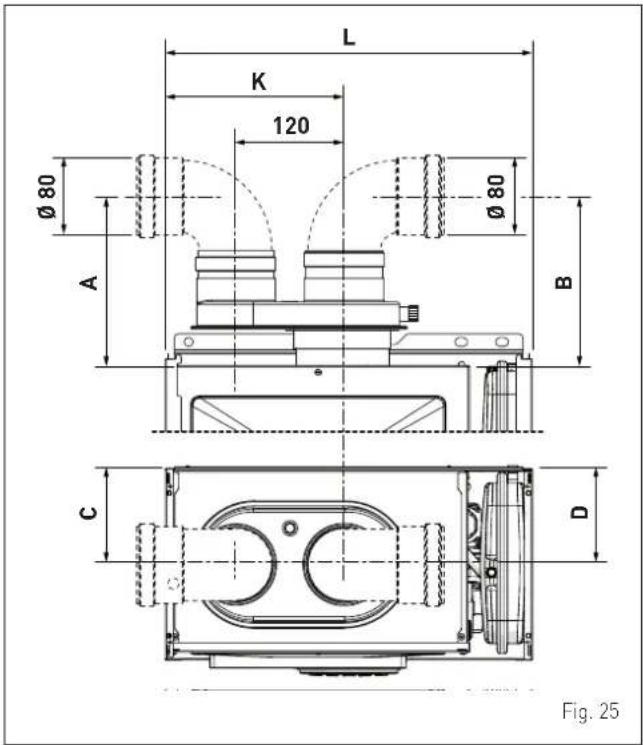
L K 120 Ø80 Ø80 A B C D Fig. 25| Description | Brava Slim 25 BF | Brava Slim 30 BF | Brava Slim 40 BF |
| K (mm) | 203 | 221 | 245 |
| W (mm) | 400 | 450 | 450 |
| A (mm) | 190 | 190 | 170 |
| B (mm) | 190 | 190 | 170 |
| C (mm) | 125 | 125 | 165 |
| D (mm) | 125 | 125 | 165 |
6.12 Electrical connections
The power cable must be connected to a 230V (±10%) \~ 50 Hz network, observing L-N polarity and the earth connection. The network must have an omnipolar switch with category III over-voltage, in compliance with the installation rules.
If this cable needs to be replaced, an original spare must be requested from Sime.
Therefore only the connections of the original components as shown in the table are needed. These are to be ordered separately from the boiler.
| DESCRIPTION CODE | |
| External sensor kit (β=3435, NTC 10KOhm at 25°C) 8094101 | |
| Power cable (dedicated) 6323875 | |
| Remote control HOME (open therm) 8092280 | |
| Remote control HOME PLUS (open therm) 8092281 | |

CAUTION
The maintenance interventions described must ONLY be carried out the professionally qualified personnel.

WARNING
Before carrying out any interventions described:
- set the main system switch to "OFF"
- close the gas valve
- make sure that no hot parts inside the appliance are touched.

text_image
OFFFig. 26
To facilitate introduction of the connection wires of the optional components into the boiler:
- remove the screws (1), pull the front panel (2) forwards and release it from the top by lifting it
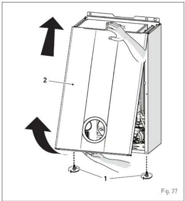
text_image
2 1 Fig. 27- remove the screws (3) securing the control panel (4)
- move the panel (4) upwards (a) but keeping it in the side guides (5) to the end of travel
- bring it forwards and down (b) until it is horizontal
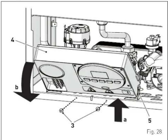
text_image
4 b a 3 5 Fig. 28- insert the connection wires into the cable gland (6) and the opening (7) on the control panel
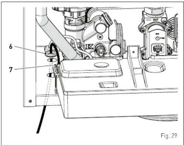
text_image
6 7 Fig. 29- bring the control panel (4) to the original position and secure it with the screws (3) which were removed previously
- connect the component wires to the terminal board (8) following the indications provided on the data plate (9).
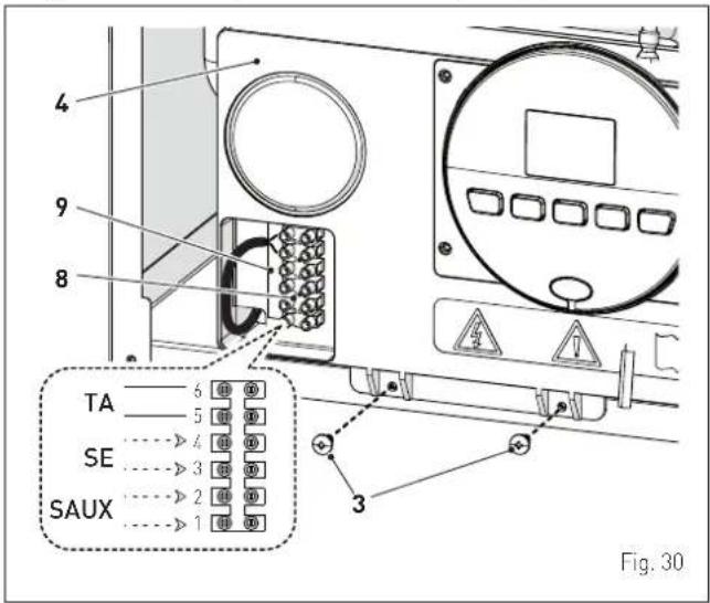
text_image
4 9 8 TA 5 SE 4 SAUX 3 Fig. 30
CAUTION
It is compulsory:
- to use an omnipolar cut-off switch, disconnect switch, in compliance with EN standards (contact opening of at least 3 mm)
- if the power cable is to be replaced, that ONLY a special cable is used with a factory produced re-wired connector, ordered as a spare part and connected by a professionally qualified person
- to connect the earth wire to an effective earthing system [*]
- that before any intervention on the boiler, the mains power is disconnected by setting the main system switch to "OFF".
(*) The manufacturer is not responsible for any damage caused by failure to earth the appliance or failure to observe the information provided in the wiring diagrams.

IT IS FORBIDDEN
To use water pipes for earthing the appliance.
6.12.1 External temperature sensor
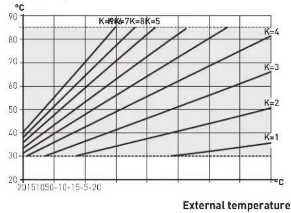
The boiler is prearranged for connection to an external air temperature sensor and can operate with a sliding temperature. This means that the delivery temperature sent to the boiler can vary on the basis of the external temperature depending on the climatic curve selected from those shown in the diagram (Fig. 31).
When fitting the sensor on the outside of the building, follow the instructions provided on the packaging of the product itself.
Climatic curve
Delivery temperature
line
| External temperature | K=1 | K=2 | K=3 | K=4 | K=5 | | --------------------- | ---- | ---- | ---- | ---- | ---- | | 2015 | 30 | 30 | 30 | 30 | 30 | | 10-50 | 30 | 30 | 30 | 30 | 30 | | 10-15 | 30 | 30 | 30 | 30 | 30 | | 5-20 | 30 | 30 | 30 | 30 | 30 | | >5 | 30 | 30 | 30 | 30 | 30 | | >15 | 30 | 30 | 30 | 30 | 30 | | >20 | 30 | 30 | 30 | 30 | 30 | | >25 | 30 | 30 | 30 | 30 | 30 | | >25 | >25 | >25 | >25 | >25 | >25 | | >25 | >25 | >25 | >25 | >25 | >25 | | >25 | >25 | >25 | >25 | >25 | >25 | | >25 | >25 | >25 | >25 | >25 | >25 | | >25 - <20 | >25 | >25 | >25 | >25 | >25 | | >25 - <15 | >25 | >25 | >25 | >25 | >25 | | >25 - <10 | >25 | >25 | >25 | >25 | >25 | | >25 - <15 | >25 | >25 | >25 | >25 | >25 | | >25 - <10 | >25 | >25 | >25 | >25 | >25 |Fig. 31

CAUTION
If there is an external sensor, in order to select the optimal climatic curve for the system and therefore the delivery temperature based on the external temperature:
- press the button 1111 for 1 second
- press buttons + or - until the required curve K has been selected (within the rangeK=0.0 - K=9.0).
6.12.2 Chrono-thermostat or Air Thermostat
The electrical connection of the chrono-thermostat or air thermostat has already been described. When fitting the component in the room where the readings are to be taken, follow the instructions provided on the packaging of the product itself.
6.12.3 EXAMPLE of use of the command/control device on some types of heating systems
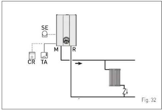
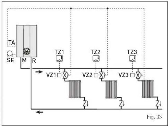
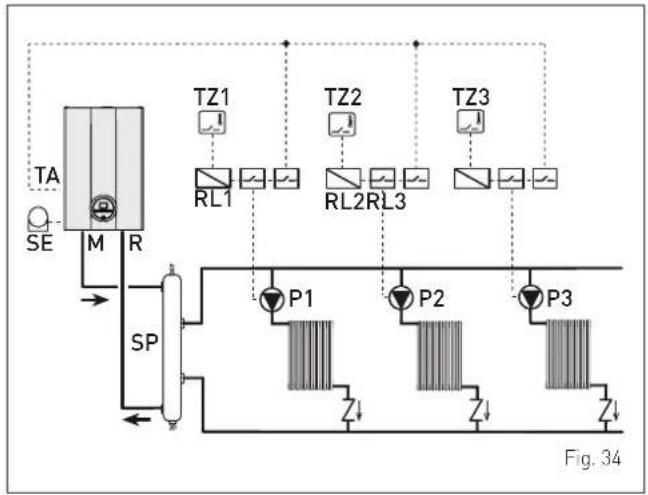
KEY
M System delivery
R System return
CR Remote control
SE External temperature sensor
TA Air thermostat for boiler activation
TZ1÷TZ3 Air thermostat for the zone
VZ1-VZ3 Zone valves
RL1-RL3 Zone relays
P1-P3 Zone pump
TSB Low temperature safety thermostat
ONE DIRECT ZONE system, external sensor and air thermostat.
flowchart
graph TD
    A["CR"] --> B["M"]
    C["TA"] --> B
    D["SE"] --> B
    B --> E["R"]
    F["Z"] --> G["Heat Exchanger"]
    style A fill:#f9f,stroke:#333
    style C fill:#f9f,stroke:#333
    style D fill:#f9f,stroke:#333
    style E fill:#ccf,stroke:#333
    style F fill:#ccf,stroke:#333
    style G fill:#cfc,stroke:#333
MULTI ZONE system - with zone valve, air thermostat and external sensor.
flowchart
graph TD
    TA["TA"] --> M["M"]
    SE["SE"] --> M
    M --> R["R"]
    R --> VZ1["VZ1"]
    R --> VZ2["VZ2"]
    R --> VZ3["VZ3"]
    VZ1 --> Z1["Z1"]
    VZ2 --> Z2["Z2"]
    VZ3 --> Z3["Z3"]
    VZ1 --> Z4["Z4"]
    VZ2 --> Z4
    VZ3 --> Z4
    TZ1 --> TZ1["TZ1"]
    TZ2 --> TZ2["TZ2"]
    TZ3 --> TZ3["TZ3"]
    style TA fill:#f9f,stroke:#333
    style SE fill:#ccf,stroke:#333
    style M fill:#cfc,stroke:#333
    style R fill:#fcc,stroke:#333
    style VZ1 fill:#cff,stroke:#333
    style VZ2 fill:#cff,stroke:#333
    style VZ3 fill:#cff,stroke:#333
    style Z1 fill:#ffc,stroke:#333
    style Z2 fill:#ffc,stroke:#333
    style Z3 fill:#ffc,stroke:#333
    style Z4 fill:#ffc,stroke:#333

CAUTION
Set the parameter "tS 17 = DELAY SYSTEM PUMP ACTI-VATION to allow the opening of zone valve Vz.
MULTI ZONE system - with pump, air thermostat and external sensor.
flowchart
graph TD
    A["Se"] --> B["M"]
    B --> C["R"]
    C --> D["SP"]
    D --> E["P1"]
    D --> F["P2"]
    D --> G["P3"]
    E --> H["TL1"]
    F --> I["TL2"]
    G --> J["TL3"]
    H --> K["TZ1"]
    I --> L["TZ2"]
    J --> M["TZ3"]
    style A fill:#f9f,stroke:#333
    style B fill:#ccf,stroke:#333
    style C fill:#cfc,stroke:#333
    style D fill:#fcc,stroke:#333
    style E fill:#ffc,stroke:#333
    style F fill:#ffc,stroke:#333
    style G fill:#ffc,stroke:#333
    style H fill:#fff,stroke:#333
    style I fill:#fff,stroke:#333
    style J fill:#fff,stroke:#333
    style K fill:#fff,stroke:#333
    style L fill:#fff,stroke:#333
    style M fill:#fff,stroke:#333
6.13 Refilling or emptying
Before carrying out the operations described below, make sure that the main system switch is set to "ON" in order for the display to show the pressure level in the system during refilling.
Make sure that the operating mode is set to "Stand-by"; if this is not the case, press the button ⏻R for at least 1 second until this mode has been selected.

text_image
ON 0.0 bar Fig. 356.13.1 REFILL operations
Remove the front panel:
- remove the two screws (1), pull the front panel (2) forwards and release it from the top by lifting it.
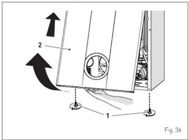
text_image
2 1 Fig. 36Domestic hot water circuit:
- open the isolation valves of the domestic hot water circuit (if present)
- open one or more than one hot water valve to fill and bleed the domestic hot water circuit
- once bleeding has been completed, close the hot water valves.
Heating circuit:
- open the isolation and air bleeding valves in the highest points of the system
- loosen the automatic bleed valve (3)
- open the isolation valves of the heating circuit (if present)
- Open the filling valve (4)
- Fill until the water overflows from the air bleeding valves and shut off the valves again
- Continue filling until the pressure reaches 1-1.2 bar as shown on the display (1)
- close the filling valve (4)
- check that there is no air in the system by bleeding all the radiators and the circuit on the high points of the system
- remove the front plug (6) of the pump and use a screwdriver to check that the impeller is not blocked
- replace the plug (6)
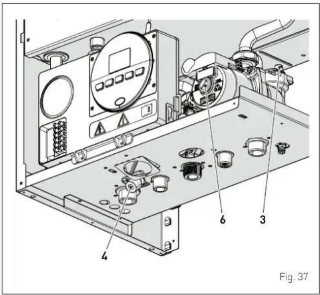
text_image
Fig. 37NOTE: to completely remove all air from the system, it is recommended that this operation is repeated a number of times.
- check the pressure on the display and if necessary top up until the correct pressure reading appears
- close the automatic bleed valve (3).
Refit the front panel of the boiler hooking it on at the top, pushing it forwards and securing it with the screw (1) which was removed previously.
6.13.2 EMPTYING operations
Domestic hot water circuit:
- close the domestic hot water circuit isolation valve (prearranged in installation)
- open one or more than one hot water valve to fill and bleed the domestic hot water circuit.
Boiler:
- loosen the automatic bleed valve [3]
- close the heating circuit isolation valves (prearranged in installation)
- check that the filling valve (4) is shut-off
- connect a rubber hose to the boiler drain valve (7) and open it
- when it has fully emptied, close the drain valve (7)
- close the automatic bleed valve (3).
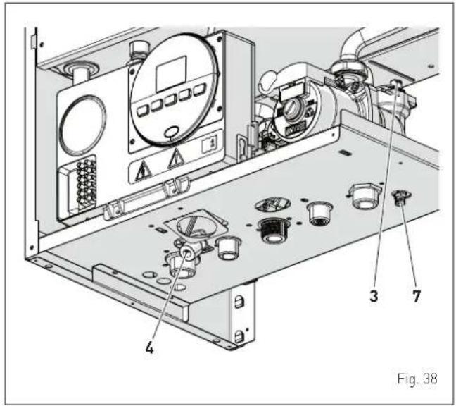
text_image
Fig. 387 COMMISSIONING
7.1 Preliminary operations

WARNING
- Should it be necessary to access the areas in the bottom part of the appliance, make sure that the system components and pipes are not hot (risk of burning).
- Before replenishing the heating system, put on protective gloves.
Before commissioning the appliance, check that:
- the type of gas is correct for the appliance
- the gas isolation valves for the heating system and the water system are open
- the pump impeller rotates freely.
7.2 Before commissioning
After having carried out the preliminary operations, perform the following to start the boiler:
- set the main system switch to "ON"
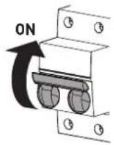
Fig. 39
- the type of gas for which the boiler has been calibrated, "nG" (methane) or "LG" (LPG,) will appear followed by the power. After this the correct representation of the symbols will be checked and finally "-"will appear on the display
text_image
1.1 bar- check that the system pressure as shown on the pressure gauge when the system is cold, is between 1 and 1.2 bar
- press the button 📍 once for at least 1 second to select "SUMMER mode" ⚙. the value of the delivery sensor detected at that moment will appear on the display
text_image
18°C L. L. bar- open one or more than one hot water tap. The boiler will work at maximum power until the taps are closed.
- if there is a fault, the message "ALL" will appear on the display, the fault code (eg. "06" - no flame detected) and the message RESET
text_image
ALL 06 RESET 11 bar
CAUTION
To restore the start conditions press and hold the button OR for more than 3 seconds. This operation can be carried out no more than 6 times.
- close the taps opened previously and check that the appliance shuts down
- press the button RESET once for at least 1 second to select "WIN-TER mode" ⚙. The value of the heating water temperature detected at that moment will appear on the display

text_image
* 38°C 11bar- adjust the air thermostat and check that the boiler starts and operates correctly
- to check that the pressure in the network and the nozzles are correct, the procedure described in section must be carried out "Chimney sweeper function".
7.3 Parameter setting and display
To go into the parameter menu:
- from the selected mode (eg. WINTER)
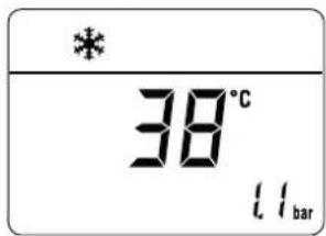
text_image
* 38°C 11bar- press the buttons and 1111 (for approximately 5 seconds) at the same time until "PAR 01" (parameter number) and the value set (0÷ 4) appears on the display
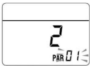
text_image
2 PAR 0 1- press the button to scroll up the list of parameters and then to scroll down the list
NOTE: holding the buttons 📋 or 1111 increases the speed of the scrolling movement.
- once the required parameter has been reached, press the buttons+ or -to modify the value within the permitted range. The modifications are stored automatically.
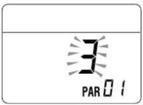
text_image
3 PAR 01When all the parameter modifications have been made, exit the parameter menu by pressing and holding down the buttons and all at the same time for at least 5 seconds until the initial screen is displayed.
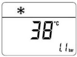
text_image
* 38°C l l bar7.4 List of parameters
| Type No. Description Range U/M Step Default | ||||||
| CONFIGURATION | ||||||
| PAR 01 | Index showing boiler power in kW | 0 = 24 kW1 = 30 kW2 = 40 kW | - 1 0 or | 1 or 2 | ||
| PAR 02 | Hydraulic configuration | 0 = rapid1 = storage tank with thermostat or heating only2 = hot water tank with sensor3 = bithermic4=instant with solar power input | - 1 0 | |||
| PAR 03 | Gas Type Configuration | 0 = G201 = GPL | - 1 | 0 or 1 | ||
| PAR 04 | Combustion configuration | 0 = sealed chamber with combustion control1 = open chamber with smoke thermostat2 = Low NOx | - 1 0 | |||
| PAR | 08 | External sensor value correction | -5 .. +5 | °C | 1 | 0 |
| DOMESTIC HOT WATER - HEATING | ||||||
| PAR | 10 | Boiler Antifreeze Threshold | 0 .. +10 | °C | 1 | 3 |
| PAR 11 | External Sensor Antifreeze Threshold-- = Disabled | -9 .. +5 | °C | 1 | -2 | |
| PAR | 12 | Heating Curve Incline | 0 .. 80 | - | 1 | 20 |
| PAR | 13 | Minimum Heating Temperature Adjustment | 20 .. PAR 14 | °C | 1 | 20 |
| PAR | 14 | Maximum Heating Temperature Adjustment | PAR 13 .. 80 | °C | 1 | 80 |
| PAR | 15 | Maximum power heating | 0 .. 100 | % | 1 | 100 |
| PAR | 16 | Heating Post-Circulation Time | 0 .. 99 | seconds x 10 | 1 | 3 |
| PAR | 17 | Heating Pump Activation Delay | 0 .. 60 | seconds x 10 | 1 | 0 |
| PAR | 18 | Re-ignition Delay | 0 .. 60 | Min | 1 | 3 |
| PAR 19 | Domestic Hot Water Modulation with Flow meter | 0 = Disabled1 = Enabled | - 1 1 | |||
| PAR | 20 | Maximum power domestic hot water | 0 .. 100 | % | 1 | 100 |
| PAR 21 | Minimum power heating/domestic hot water (premixed) | 0 .. 100 | % | 1 0 | ||
| PAR 22 | Domestic hot water preheating enabling | 0 = OFF1 = ON | - 1 0 | |||
| PAR 23 | External relay 1 function | 0 = not used; 1 = remote alarm NO; 2 = remote alarm NC; 3 = zone valve; 4 = automatic filling; 5 = external request; 6 = recirculation pump; 7 = zone valve with OT; 8 = relaunch pump | - | - 0 | ||
| PAR 24 | External relay 2 function | 0 = not used; 1 = remote alarm NO; 2 = remote alarm NC; 3 = zone valve; 4 = automatic filling; 5 = external request; 6 = recirculation pump; 7 = zone valve with OT; 8 = relaunch pump | - | - 0 | ||
| PAR 25 | Auxiliary TA function | 0 = according to TA1 = TA Antifreeze2= domestic hot water disabled | -10 | |||
| PAR | 26 | Zone Valve / Pump Relaunch Delay | 0..99 | Min | 1 | 1 |
| PAR | 28 | DHW activation delay with solar power | 0..30 | Min | 1 | 0 |
| PAR 29 | Anti-legionella Function [Only hot water tank]-- = Disabled | 50..80 | -1 | -- | ||
| PAR | 30 | Maximum domestic hot water temperature | 35..67 | °C | 1 | 60 |
| PAR 35 | Digital / analogue Pressure switch | 0 = water pressure switch1 = water pressure transducer2 = water pressure transducer (only pressure displayed) | -11 | |||
| PAR 40 | Modulating Pump Speed | -- = No modulation AU = Automatic 30..100 | % | 10 | AU | |
| PAR | 41 | ΔT Modulating pump delivery/Return | 10..40 | °C | 1 | 20 |
| PAR 47 | System | pump forcing (only in winter mode) | 0 = Disabled1 = Enabled | -10 | ||
| RESET | ||||||
| PAR | 48 | INST Parameter set to default | 0..1 | - | - | 0 |
In the event of a fault/malfunction the message "ALL" will appear on the display with the alarm number eg. "ALL 04" (Domestic Hot Water Sensor Fault).

text_image
ALL 04 L1 barBefore repairing the fault:
- disconnect the appliance from the mains power by setting the main switch to "OFF"
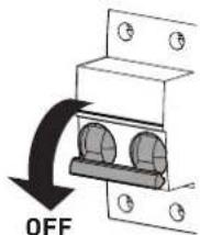
text_image
OFFFig. 40
- as a precautionary measure, close the gas isolation valve.
Repair the fault and start-up the boiler again.
NOTE: after having repaired the fault, when the alarm number appears on the display together with the message RESET (see figure), press the button OR for approximately 3 seconds to start the appliance up again.
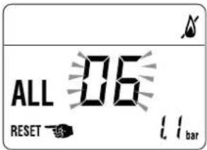
text_image
ALL 06 RESET 1.1 bar7.5 Display of operating data and counters
Once the boiler is operating a qualified technician can view the operating data and the counters as follows:.
From the operating screen in the mode enabled at that moment (WINTER or SUMMER):

text_image
* 38°C 1.1bar 18°C 1.1bar- go into "DISPLAY" by pressing the buttons 📂 and — at the same time for more than 3 seconds until the following screen appears
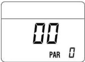
text_image
00 PAR 0From this point, the technician has 2 options:
- scroll through the list of "information (PAR)" and "counters (PARc)" by pressing the button 1111. Scrolling will be in sequence
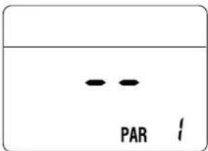
text_image
PAR 1- display the "activated alarms" (no more than 10) by pressing the button
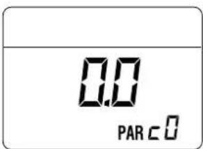
text_image
0.0 PAR C 0- Once in this section, proceed with button 111 or 2.
When all the values have been displayed, exit the menu by pressing and holding down the button ⓍRfor approximately 5 seconds until the initial screen is displayed.
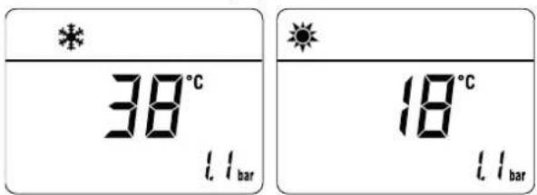
text_image
* 38°C 18°C 11bar 11barTABLE OF INFORMATION DISPLAYED
| Type No. | Description | Range | U/M Step | ||
| PAR 00 | SW version | ||||
| PAR | 01 | External sensor | -9..99 | °C | 1 |
| PAR 02 | Delivery sensor 1 temperature | -9..99 | °C 1 | ||
| PAR 03 | Delivery sensor 2 temperature | -9..99 | °C 1 | ||
| PAR 04 | Domestic hot water sensor temperature | -9..99 | °C 1 | ||
| PAR | 05 | AUX auxiliary sensor | -9..99 | °C | 1 |
| PAR 06 | Actual heating SET temperature | Par. 13 ... Par. 14 | °C 1 | ||
| PAR | 07 | Power level | 0..99 | % | 1 |
| PAR | 08 | Flow meter rate | 0..99 | l/min | 0.1 |
| PAR 09 | Water pressure transducer reading (if resent) | 0...99 bar | 0.1 | ||
TABLE OF COUNTER DISPLAYED
| Type No. | Description | Range | U/M Step | |
| PAR c0 | total no. of boiler operating hours | 0 .. 99 | h x 1000 | |
| PAR c1 | total no. of burner operating hours | 0 .. 99 | h x 1000 | |
| PAR c2 | total no. of burner ignitions | 0 .. 99 | h x 1000 | |
| PAR | c3 | total no. faults | 0 .. 99 | x 1 |
| PAR c4 | total no. of times PAR parameters accessed | 0 .. 99 x 1 | 1 | |
| PAR c5 | total no. of times OEM parameters accessed | 0 .. 99 x 1 | 1 | |
| PAR c6 | time unitl next main-tenance intervention | 0 .. 99 months | 1 | |
TABLE OF ACTIVATED ALARMS/FAULTS
| Type No. | Description | |
| PAR | A0 | Last activated alarm/fault |
| PAR | A1 | Last but one activated alarm/fault |
| PAR | A2 | Third from last activated alarm/fault |
| PAR | A3 | Previous activated alarm/fault |
| PAR | A4 | Previous activated alarm/fault |
| PAR | A5 | Previous activated alarm/fault |
| PAR | A6 | Previous activated alarm/fault |
| PAR | A7 | Previous activated alarm/fault |
| PAR | A8 | Previous activated alarm/fault |
| PAR | A9 | Previous activated alarm/fault |
7.6 Checks and adjustments
7.6.1 Chimney sweeper function
The chimney sweeper function is used by the qualified maintenance technician to check the gas pressure at the nozzles, detect the combustion parameters and to measure the combustion efficiency required by legislation in force.
This function lasts 15 minutes and is activated by proceeding as follows:
- if the panel (2) has not already been removed, remove the two screws (1), pull the front panel (2) forwards and release it from the top by lifting it
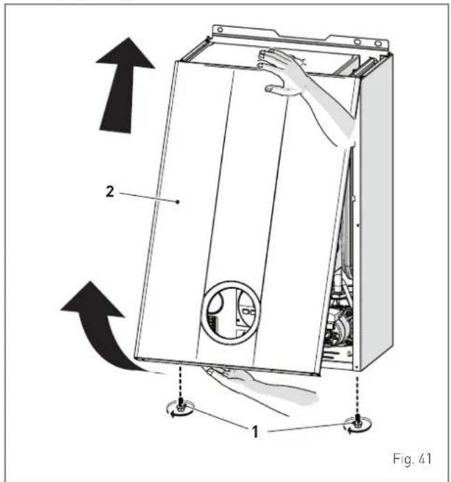
text_image
2 1 Fig. 41- remove the screws (3) securing the control panel (4)
- move the panel (4) upwards (a) but keeping it in the side guides (5) to the end of travel
- bring it forwards and down (b) until it is horizontal
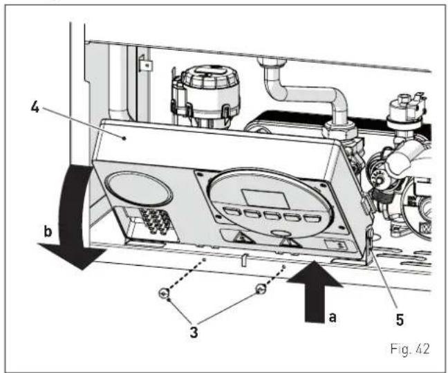
text_image
4 b 3 a 5 Fig. 42- close the gas valve
- loosen the "nozzle pressure" point (6) and the screw of the "supply pressure" point (7) and connect each one to a pressure gauge
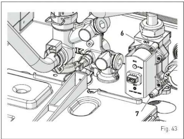
text_image
6 7 Fig. 43- open the gas valve
- power the boiler by setting the main switch to "ON"
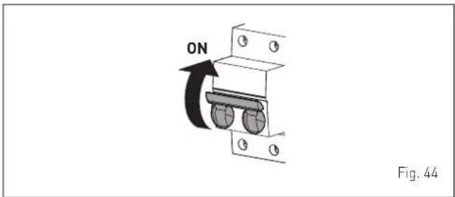
text_image
ON Fig. 44- press the button OR for at least 1 second until "SUMMER" mode has been selected
- press and hold down the buttons— and + at the same time for approximately 10 seconds until the message “Hi” appears on the display together with the flashing symbols ⚙️ and ✕
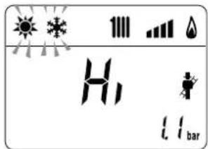
text_image
H L bar- open one or more than one hot water tap
- press the button + to make the boiler operate at maximum power "Hi" and check that the gas pressure values on the pressure gauges correspond to those indicated in the table below
- press the button - to make the boiler operate at minimum power "Lo" and check that the gas pressure values on the pressure gauges correspond to those indicated in the table below. The message "Lo" will appear on the display together with the flashing symbols 🙏 and 🚫
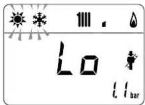
text_image
111. Lo 11 bar- press the button + once again to make the boiler operate at maximum power. If the gas pressure values are correct it is possible to determine the combustion data and take a reading of the combustion efficiency as provided for by legislation in force
- press the button ⬇R to exit the "Chimney sweeper Procedure". The boiler water delivery temperature will appear on the display

text_image
*38°C L11bar- close the taps opened previously and check that the appliance shuts down
- disconnect the pressure gauges, carefully close the pressure points (6) and (7), put the control panel back to the original position and refit the front panel (2).
Gas supply pressure
| Type of gas G20 G30 G31 | |||
| Pressure (mbar) 20 | 28-30 37 | ||
Installation with SPLIT PIPE SYSTEM smoke outlet
Installation with CONCENTRIC smoke outlet
If the gas pressure values are different from the values indicated in the table, adjust the gas nozzle pressure as described in the section below.
7.6.2 Adjusting gas pressure at the nozzles

CAUTION
Considering that:
- the front panel (2) has already been removed and the point (6) is connected to the pressure gauge
- the main system switch must be set to "ON"
- the gas supply must be open
- there must be no current requests for heat ("Summer" mode with hot water valve closed or "Winter" with air thermostats open)
- the adjustments described below must be carried out in sequence.
Adjusting maximum gas pressure:
- press button ⚙ and set the DOMESTIC HOT WATER SET to maximum using the button +
- press and hold down the buttons + and ⏻R at the same time for approximately 6 seconds until the message "MA" appears on the display alternating with "nu"
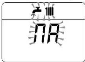
text_image
719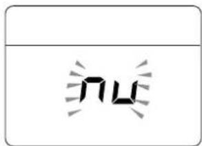
text_image
nu- open one or more than one hot water tap
- the boiler will start up and the message "P01" will appear on the display (Adjusting maximum gas pressure)
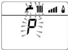
text_image
Diagram showing a digital display with icons for power, battery, and water droplets, likely representing a power system or sensor setup.
text_image
0- press the buttons + or - until the pressure value indicated in the table appears on the pressure gauge
- once the value indicated in the table has been reached, press the button OR for approximately 2 seconds to confirm the value which will then flash once.
Adjusting minimum gas pressure:
- press the button twice, the message "P00" will appear on the display
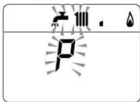
text_image
P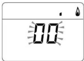
text_image
00- press the buttons+ or - until the pressure value indicated in the table appears on the pressure gauge
- once the value indicated in the table has been reached, press the button OR for approximately 2 seconds to confirm the value which will then flash once.
- press and hold down the buttons + and ⏻R at the same time for approximately 6 seconds until the water delivery temperature appears on the display and the boiler shuts down/starts up
- close the valves which were opened previously.
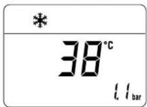
text_image
* 38°C 1.1 bar7.7 Gas conversion
Brava Slim BF models can be converted from operation with G20 to operation with G30/G31 by installing the "Nozzle kit for G30/G31 - code 5144716 (for Brava Slim 25 BF), 5144713 (for Brava Slim 30 BF) and code 5144725 (for Brava Slim 40 BF) to be ordered separately from the boiler.

CAUTION
The maintenance interventions described must ONLY be carried out the professionally qualified personnel.

WARNING
Before carrying out any interventions described:
- set the main system switch to "OFF"
- close the gas valve
- make sure that no hot parts inside the appliance are touched.
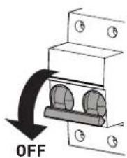
text_image
OFFFig. 45
7.7.1 Preliminary operations
To carry out the conversion:
- remove the screws (1), pull the front panel (2) forwards and release it from the top by lifting it
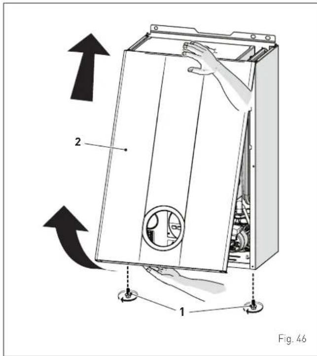
text_image
2 1 Fig. 46- remove the four screws (3) and remove the front panel (4) from the sealed chamber
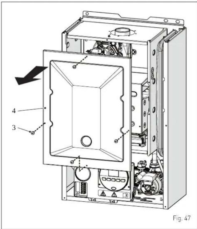
text_image
4 3 Fig. 47- remove the four screws (3) and remove the front panel (4) from the combustion chamber (6) working carefully so as not to damage the gasket or the panel insulation
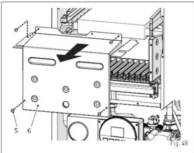
text_image
5 6 Fig. 48- remove the screw (7) and extract the electrode (8)
- remove the swivel joint (9) and the counter-nut (10)
- remove the screws (11)
- remove the gas manifold [12], replace the nozzles fitted in the factory with the nozzles supplied with the accessory kit and position the gaskets
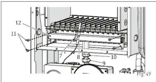
text_image
12 11 7 8 9 10 Fig. 49-
refit the gas manifold (12) securing it with the screws (11)
-
tighten the counter-nut (10) and the swivel joint (9) and position the gasket
- refit the electrode (8) putting its end IN THE MIDDLE of the burner element (*)
- check that the gasket and the insulation of the front panel (6) of the combustion chamber and the gasket (13) of the front panel (4) of the sealed chamber are all integral. If they are not, replace them
- refit the panels (6) and (4) securing them with fastening screws

CAUTION (\*)
The position of the electrode is essential for the correct detection of current ionization.
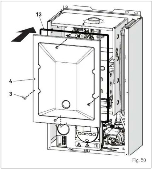
text_image
13 4 3 Fig. 50- apply the label indicating the new gas configuration on the technical plate (14) on the inside of the front panel
- carry out the "Automatic calibration procedure" and then refit the front panel (2) securing it with the two screws (1).
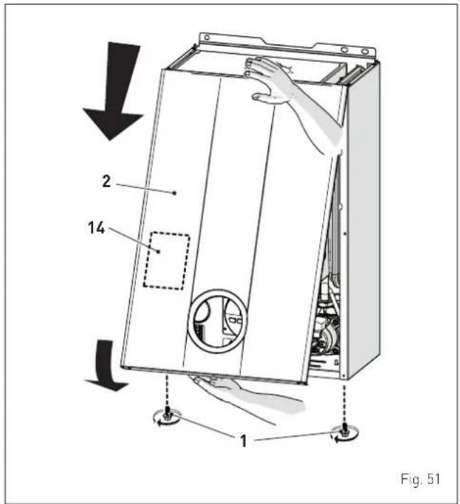
text_image
2 14 1 Fig. 517.8 Automatic calibration procedure
This procedure MUST ALWAYS be performed when the appliance is first turned on, when the gas is changed and after replacing:
- the nozzles for gas conversion
- the gas valve following a fault
- the electronic board following a fault
- electrode
- fan
- burner
and is necessary so that the new components can be identified and can communicate with those already fitted on the boiler.

CAUTION
Considering that:
- the front panel has been removed, the control panel has been brought forward and down and that the points (6) and (7) of the gas valve have been connected to the pressure gauges
- the main system switch must be set to "ON"
- the gas supply must be open
- there must be no current requests for heat ("Summer" mode with hot water valve closed or "Winter" with air thermostats open)
- the adjustments described below must be carried out in sequence.
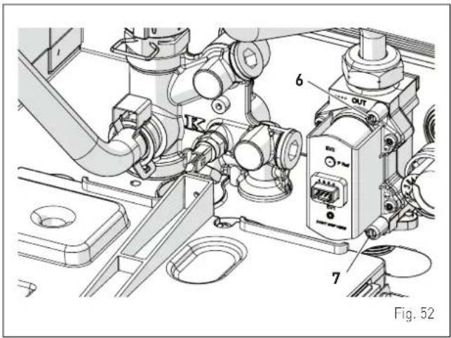
text_image
6 OUT EN 7 Fig. 52Procedure valid for GAS CONVERSION
- go into the parameter section by pressing the buttons and 111 (for approximately 5 seconds) at the same time until "PAR 01" (parameter number) and the value set (0-4) appears on the display
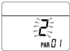
text_image
2 PAR 01NOTE: holding the buttons 📁 or 🌐 increases the speed of the scrolling movement. Pressing the button 📁 allows the user to scroll through the previous parameters.
- keep the button 1111 pressed and scroll through the parameters until reaching parameter "03"
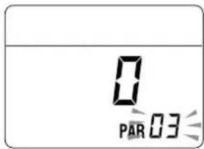
text_image
0 PAR 03- press the button+ and select "1" (LPG)
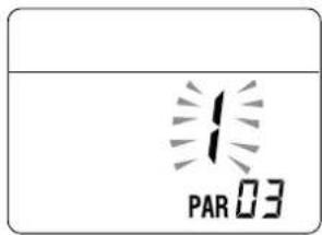
text_image
PAR 03Procedure which MUST be carried out after:
- the nozzles for gas conversion
- changing the gas valve following a fault
- changing the the electronic board following a fault
- electrode
- fan
- burner
- go into the parameter section (if not already there) by pressing the buttons and 1111 (for approximately 5 seconds) at the same time until "PAR 01" (parameter number) and the value set [0-4] appears on the display
- keep the button 1111 pressed and scroll through the parameters until reaching parameter "PAR 49"
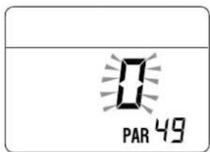
text_image
PAR 49- press and hold the button+ to set the valueat "49"
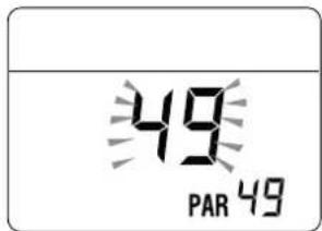
text_image
49 PAR 49- the modified value will be stored automatically
- keep the button 1111 pressed and scroll through the parameters until reaching parameter "PAR 70"
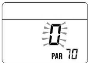
text_image
PAR 70- press the button+ to set the valueat "5"
- the modified value will be stored automatically
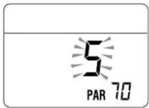
text_image
5 PAR 70- exit the parameter section by pressing and holding down the buttons and at the same time (approximately 5 seconds) until the delivery temperature is displayed.
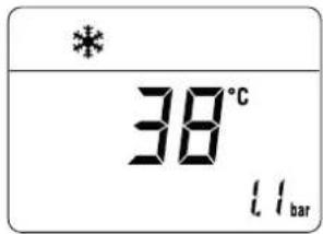
text_image
* 38°C 11bar
IMPORTANT
To complete this task the user MUST carry out the following procedure.
Adjusting maximum gas pressure:
- press the button OR until "SUMMER" mode has been selected
- press button ⚙️ and set the DOMESTIC HOT WATER SET to maximum using the button +
- press and hold down the buttons + and ⏻R at the same time for approximately 6 seconds until the message "Au" appears on the display alternating with "to"
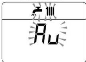
text_image
FLU
text_image
tāo- open one or more than one hot water tap
- the boiler will start up and the message "P01" will appear on the display (Adjusting maximum gas pressure)
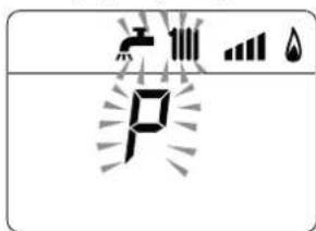
text_image
Diagram showing electrical circuit symbols including a power source, current source, and water drop with Chinese label 'P'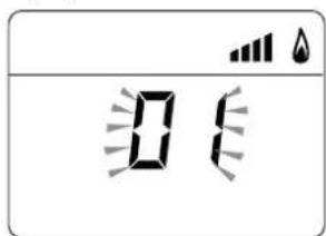
text_image
Digital display showing '0' with battery icons above and below, likely indicating a timer or digital status.- press the buttons + or - until the pressure value indicated in the table appears on the pressure gauge
- once the value indicated in the table has been reached, press the button ⏻R for approximately 2 seconds to confirm the value which will then flash once.
Adjusting minimum gas pressure:
- press the button twice, the message "P00" will appear on the display
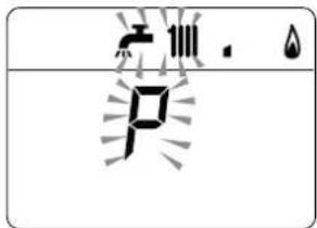
text_image
水 P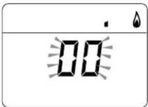
text_image
00- press the buttons + or - until the pressure value indicated in the table appears on the pressure gauge
- once the value indicated in the table has been reached, press the button OR for approximately 2 seconds to confirm the value which will then flash once
- press and hold down the buttons+ and ⏻R at the same time for approximately 6 seconds until the water delivery temperature appears on the display and the boiler shuts down
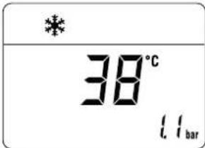
text_image
* 38°C 1.1bar- close the valves which were opened previously
- disconnect the pressure gauges, carefully close the pressure points (6) and (7), put the control panel back to the original position and refit the front panel (2).
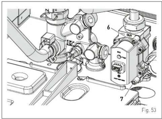
text_image
6 7 Fig. 53Gas supply pressure
| Type of gas G20 | G30 G31 | ||
| Pressure (mbar) | 20 28-30 37 |
Installation with SPLIT PIPE SYSTEM smoke outlet
Installation with CONCENTRIC smoke outlet
7.9 Domestic hot water comfort function (preheating)
Brava Slim BF models have a "domestic hot water comfort" function which ensures the best performance in terms of domestic hot water, reducing the time necessary for the hot water to become available and ensuring that the temperature is stable.
To activate the function:
- select parameter"PAR 22" (see "Parameter setting and display") and set it to a 1
- exit parameter settings and press button + for approximately 5 seconds until the symbol ✗ appears on the display and begins to flash indicating that the function has been activated.

text_image
1.1 barTo deactivate the function:
- press button + again for approximately 5 seconds until the symbols ✗ and RESET appear on the display and begin to flash indicating that the function has been deactivated.

text_image
RESET 1.1 bar8.1 Adjustments
For the appliance to operate correctly and efficiently it is recommended that the User calls upon the services of a Professionally Qualified Technician to carry out ANNUAL maintenance.

CAUTION
- The maintenance interventions described must ONLY be carried out the professionally qualified personnel who MUST wear suitable protective safety equipment.
- Make sure that the system components and pipes are not hot (risk of burning).

WARNING
Before carrying out any interventions described:
- set the main system switch to "OFF"
- close the gas valve
- make sure that no hot parts inside the appliance are touched.
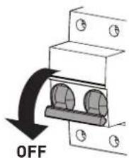
text_image
OFFFig. 54
8.2 External cleaning
8.2.1 Cleaning the cladding
When cleaning the cladding, use a cloth dampened with soap and water or alcohol for stubborn marks.

IT IS FORBIDDEN
to use abrasive products.
8.3 Cleaning the inside of the appliance
8.3.1 Cleaning the heat exchanger
To clean the heat exchanger:
- remove the screws (1), pull the front panel (2) forwards and release it from the top by lifting it
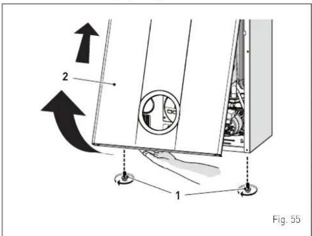
text_image
2 1 Fig. 55- remove the four screws (3) and remove the front panel (4) from the sealed chamber
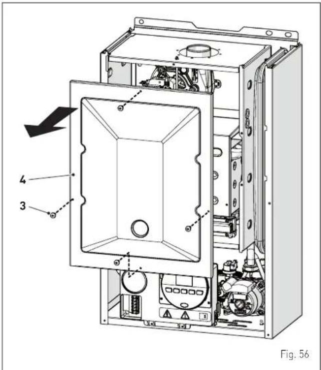
text_image
Fig. 56- remove the four screws (3) and remove the front panel (4) from the combustion chamber (6) working carefully so as not to damage the gasket or the panel insulation
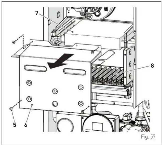
text_image
7 8 5 6 Fig. 57- if there is any dirt on the heat exchanger (7) fins, protect the burner elements (8) covering them with a sheet of newspaper or a cloth and brush the heat exchanger (7) clean.
8.3.2 Cleaning the burner
The burner does not require any particular maintenance simply dust it with a soft brush.
8.3.3 Checking the ignition/detection electrode
Check the state of the ignition/detection electrode and replace if necessary. Check the measurements as per the drawing whether the ignition/detection electrode is replaced or not.
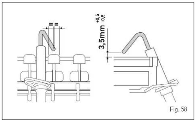
text_image
H +0,5 -0,5 3,5mm Fig. 58
CAUTION
The position of the electrode is essential for the correct detection of current ionization.
8.3.4 Final operations
After having cleaned the heat exchanger and the burner:
- remove any carbon residue using a vacuum cleaner
- check that the gasket and the insulation of the front panel (6) of the combustion chamber and the gasket (13) of the front panel (4) of the sealed chamber are all integral. If they are not, replace them
- refit the panels (6) and (4) securing them with fastening screws.
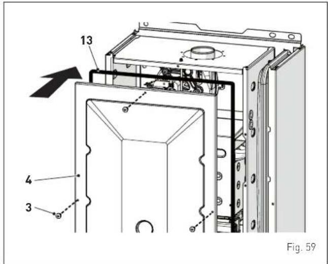
text_image
13 4 3 Fig. 598.4 Checks
8.4.1 Checking the smoke duct
It is recommended that the user checks that the combustion air inlet duct and smoke outlet duct are integral and airtight.
8.4.2 Checking the expansion vessel pressure
It is recommended that the expansion vessel on the water side is drained and that the prefilling pressure is not less than 1 bar. If this is not the case, pressurize it to the correct value (see section "Expansion vessel").
Once the checks described above have been completed:
- refill the boiler as described in section "REFILL operations"
- start the boiler up and carry out a smoke analysis and/or measure the combustion efficiency
- refit the front panel securing it with the two screws which were removed previously
8.5 Unscheduled maintenance
If replacing the electronic board, the user MUST set the parameters as indicated in the table and in the sequence shown.
| Type No. Description | Setting for Brava Slim BF | ||||
| 25 30 | 40 | ||||
| PAR 01 | Index showing boiler power in kW0 = 24; 1 = 30; 2 = 40 | 0 1 2 | |||
| PAR 02 | Hydraulic configuration0 = rapid1 = storage tank with thermostat or heating only2 = hot water tank with sensor3 = bithermic4=instant with solar power input | 0 | |||
| PAR 03 | Gas Type Configuration0 = G20; 1 = LPG | 0 or 1 | |||
| PAR 04 | Combustion configuration0 = sealed chamber with combustion control1 = open chamber with smoke thermostat2 = Low NOx | 0 | |||
To enter "Parameter setting and display" refer to the indications provided in the specific section.
Once the parameters in the table have been set, you must carry out the "Automatic calibration procedure".
If the gas valve and/or the ignition/detection electrode and/or the fan are replaced, the user must still carry out the entire phase of "Automatic calibration procedure" described in the specific section.
8.6 Malfunction codes and possible solutions LIST OF MALFUNCTION/FAULT ALARMS
| Type No. Fault | Solution | ||
| ALL 01 | Smoke | thermostat | - Contact the Technical Assistance Centre |
| ALL 02 | Low water pressure in system | - Restore pressure- Check for any leaks in the system | |
| ALL 03 | High water pressure in system | - Empty the system via the drain valve on the hydraulic assembly and bring the pressure to approximately 1.2 bar | |
| ALL 04 | Domestic hot water sensor fault (return sensor fault for T models) | - Check connections- Check the sensor is working | |
| ALL 05 | Delivery sensor fault | - Check connections- Check the sensor is working | |
| ALL 06 | No flame detection | - Check the integrity of the electrode and check that it is not grounded- Check gas availability and pressure- Check the integrity of the gas valve and the card | |
| ALL 07 | Sensor or safety thermostat intervenes | - Check the sensor or thermo - stat connections- Deaerate the system- Check the bleed valve- Replace the sensor or the thermostat- Check that the pump impeller is not blocked | |
| ALL 08 | Fault in the flame detection circuit | - Check the integrity of the electrode and check that it is not grounded- Check the integrity of the gas valve and the card | |
| Type No. Fault | Solution | |
| ALL 09 | No water circulating in the system | - Check the rotation of the pump rotor- Check the electrical connections- Replace the pump |
| ALL 10 Auxiliary sensor fault | - Check PAR 02 "hydraulic configuration"- Check the electrical connection | |
| ALL 11 | Gas valve modulator disconnected | - Check the electrical connection |
| ALL 12 | Domestic hot water sensor fault in tank mode | - Set the parameter PAR 04 (Combustion configuration) to 0 |
| ALL 13 | Smoke probe inter-vention | - Check the sensor is working- Replace the smoke probe |
| ALL 14 Smoke | probe fault | - Replace the smoke probe- Check the electrical con- nection of the smoke probe- Contact the Technical Assistance Centre |
| ALL 15 | Fan check cable dis- connected | - Check the connection cable between the fan and the board |
| ALL 18 Conder | sate level fault | - Check for any clogging in the pipe which takes the condensate to the siphon- Check that the siphon is not clogged |
| ALL 28 | Maximum number of consecutive resets reached | - Wait 1 hour and try un- blocking the board again- Contact the Technical Assistance Centre |
| ALL 30 | Return sensor fault (boiler sensor fault for T models) | - Replace the return probe- Check parameters- Contact the Technical Assistance Centre |
| ALL 37 | Fault due to low net- work voltage | - Check the voltage- Contact your network provider |
| ALL 40 | Incorrect network frequency detected | - Contact your network provider |
| ALL 41 | Flame loss more than 6 consecutive times | - Check the ignition/detec- tion electrode- Check the gas supply (open valve)- Check mains gas pressure |
| ALL 42 Button | fault | - Check that buttons are working |
| ALL 43 | Open Therm communi- cation fault | - Check the OT electric connection |
| ALL 44 | No flame valve opening time sum anomaly | - Check for the presence of water hammer on the hot water system and, if present, mount a water hammer arrestor- Check for any abnormal requests on the room thermostat- Contact the Technical Assistance Centre |
| ALL 56 | Lock for T delivery/return over max limit (open vent) | - Contact the Technical Assistance Centre |
| ALL 57 | Lock for flow temper- ature (FT) check (open vent) | - Contact the Technical Assistance Centre |
| ALL 62 | Self-calibrating proce- dure is required | - Carry out the self-cali- brating procedure (see the specific section) |
| ALL 72 | Incorrect positioning of the delivery sensor | - Check delivery sensor operation and position |
| ALL 74 | Second delivery sensor fault | - Check second delivery sensor operation and position |
| ALL 77 | EV2 SGV current max/ min absolute limits error | - Check gas valve and board |
| ALL 78 | EV2 SGV current upper limit error | - Check gas valve and board |
| ALL 79 | EV2 SGV current lower limit error | - Check gas valve and board |
| ALL 80 | Fault on the valve control logic line/valve cable damaged | - Check gas valve and board |
| ALL 81 | Block due combustion during start-up | - Check for blockage in chimney- Check air diaphragm (for BF models)- Check gas calibration- Bleed the air from the gas circuit |
| ALL 82 | Block due to numerous combustion control failures | - Check electrode- Check outlets- Check air diaphragm (for BF models)- Check gas calibration |
| ALL 83 | Irregular combustion (temporary error) | - Check for blockage in chimney- Check air diaphragm (for BF models)- Check gas calibration |
| ALL 84 | Flow rate reduced for (presumed) low pressure on mains gas | - Check gas flow rate |
| ALL 88 | Internal error (board component protection) | - Check the board is working- Replace board |
| ALL 89 | Unstable combustion feedback signal error | - Check electrode- Check outlets- Check air diaphragm (for BF models)- Check gas calibration |
| ALL 90 | Combustion set cannot be reached error | - Check electrode- Check outlets- Check air diaphragm (for BF models)- Check gas calibration |
| ALL 91 | Gas valve out of range - Recalibrate | - Check electrode- Check outlets- Check air diaphragm (for BF models)- Check gas calibration |
| ALL 92 | System has reached maximum air correction error (at the minimum flow rate) |
| Type No. Fault | Solution | ||
| ALL 93 | Combustion set cannot be reached error | - Check electrode- Check outlets- Check air diaphragm (for BF models)- Check gas calibration | |
| ALL 95 | Flame signal micro interruptions error | - Check electrode- Check board- Check electric power supply- Check gas calibration | |
| ALL 96 | Block due to clogging in smoke outlet | - Check for blockage in chimney- Check the smoke outlet and electrode position (not touching the burner) | |
| ALL 98 | SW error, board start-up | - Contact the Technical Assistance Centre | |
| ALL 99 | General | board error | - Contact the Technical Assistance Centre |
| - | - | Frequent relief valve intervention | - Check circuit pressure- Check expansion vessel |
| - | - | Limited production of domestic hot water | - Check the diverter valve- Check that plate heat exchanger is clean- Check domestic hot water circuit valve |
8.6.1 Maintenance request
When it is time to perform maintenance on the boiler, the symbol shows on the display.
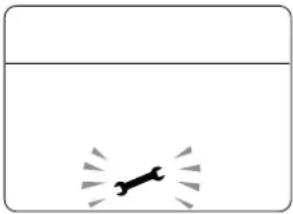
natural_image
Simple diagram with a rocket icon and radiating lines, no text or symbols presentContact the technical assistance service to organise the necessary work.
sime®
Fonderie Sime S.p.A - Via Garbo, 27 - 37045 Legnago (Vr)
Tel. +39 0442 631111 - Fax +39 0442 631292 - www.sime.it
sime®
Fonderie Sime S.p.A - Via Garbo, 27 - 37045 Legnago (Vr)
Tel. +39 0442 631111 - Fax +39 0442 631292 - www.sime.it
natural_image
Simple diagram with a horizontal line above a vertical rectangle and a small black figure inside, no text or symbols present.text_image
Technical diagram of a mechanical assembly with labeled components and numbered partsمستوى ضغط الغاز
text_image
Diagram showing electrical circuit symbols including a diode, power source, and ground symbol with Chinese labels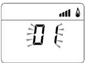
text_image
0 ↑ ↓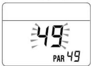
text_image
49 PAR 49text_image
Technical diagram of industrial piping system with labeled components and directional arrowstext_image
Diagram of a refrigerator interior with labeled parts and directional arrows indicating movement or assembly.46 alشكل
text_image
Diagram showing a digital display with icons for power, battery, and water droplets, likely representing a power system or sensor setup.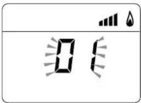
text_image
Digital display showing '0' with battery icons and a droplet symbol above itمستوى ضغط الغاز
text_image
Diagram showing electrical circuit symbols including a power source, diode, and ground connection with Chinese characters.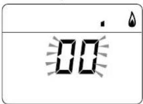
text_image
00| (mbar) مستوى الضغط عند الفؤّهات | الطاقة الحراRoة | الموديل | ||
| G31 | G30 | G20 | ||
| 36,2 - 35,8 | 28,2 - 27,8 | 12,9 - 12,5 | Maxالحد الأقصى | Brava Slim 25 BF |
| 4,2 - 3,9 | 3,4 - 3,1 | 2,0 - 1,7 | minالحد الأ chin | |
| 36,2 - 35,8 | 28,2 - 27,8 | 13,3 - 12,9 | Maxالحد الأقصى | Brava Slim 30 BF |
| 5,1 - 4,8 | 4,1 - 3,8 | 1,7 - 1,4 | minالحد الأ chin | |
| 35,2 - 34,8 | 27,2 - 26,8 | 11,6 - 11,2 | Maxالحد الأقصى | Brava Slim 40 BF |
| 3,2 - 2,9 | 2,7 - 2,4 | 1,1 - 0,8 | minالحد الأ chin | |
text_image
6 OUT 7 43الفحوصات وعمليً
7.6 ات الض Strip
خاصد
٦.6.1 ئظيف المدخلة
text_image
Diagram of a refrigerator interior with labeled parts and directional arrows indicating movement or change.41 alشكل
text_image
Diagram illustrating a door mechanism with labeled parts and directional arrows indicating movement or assembly.27 alشكل
text_image
Technical diagram of a mechanical assembly with numbered components for identification23 alشكل
اللوحة التعريفية:
۱ فاصل به مآخد
2 حاجزفصل الشفط
الهواة شفط
4 منقد طرد الأدخنة
text_image
Technical diagram of a refrigerator with labeled parts and structural annotations19 alشكل
تحذير
natural_image
Simple line drawing of a rectangular box with internal compartments and arrows indicating movement (no text or symbols)15 الشكل
natural_image
Technical line drawing of a rectangular electronic device with labeled dimensions H, L, and P (no text or symbols beyond labels)16 alشكل
text_image
Technical diagram of an internal combustion chamber with numbered components for identification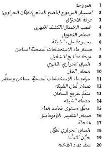
text_image
Technical diagram of a mechanical device with numbered components labeled 11 to 16.10 alشكل
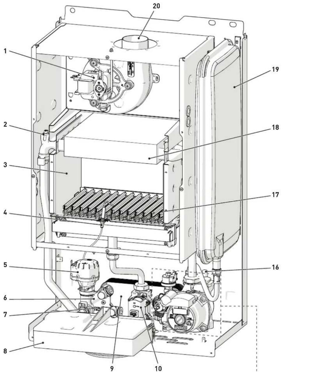
text_image
Technical diagram of an internal combustion engine unit with numbered components for identificationtext_image
Technical diagram of a mechanical device with numbered components labeled 11 to 16.للكريف
- إذا lithium Pressure adochlan into the management of the world's country in the Great States. We will be interested in the United States and have been a great opportunity to support the power of the United States. We will also be able to provide information about the U.S. government, and we will also be able to provide information about the U.S. government.
natural_image
Simple line drawing of a dog jumping out of water (no text or symbols)text_image
SET 40°C 11 barفحوصات تحضيرّ
1.2 à
انته

natural_image
White industrial water heater unit with digital display and control buttons (no visible text or symbols)العربيّة