
FUEL EV - Boiler SIME - Free user manual and instructions
Find the device manual for free FUEL EV SIME in PDF.


| Product Type | Gas Boiler (Condensing) |
| Brand | SIME |
| Model | FUEL EV |
| Dimensions (H x W x D) | 800 x 500 x 300 mm |
| Weight | 52 kg |
| Power Supply | Natural Gas / Propane |
| Nominal Heat Output | 28 kW |
| Efficiency (Seasonal Space Heating) | 92% (ErP Class A) |
| Water Connections | Flow and Return: 3/4" BSP |
| Safety Features | Overheat protection, flame failure device, frost protection, pressure relief valve |
| Control System | Electronic modulation, weather compensation compatible |
| Maintenance Frequency | Annual service recommended |
| Spare Parts Availability | Genuine SIME parts available for minimum 10 years |
| Installation Type | Wall-mounted or floor-standing |
| Energy Source | Gas (natural or LPG) |
| Noise Level | < 48 dB(A) |
| Compliance | CE, ErP Directive |
Frequently Asked Questions - FUEL EV SIME
User questions about FUEL EV SIME
0 question about this device. Answer the ones you know or ask your own.
Ask a new question about this device
Download the instructions for your Boiler in PDF format for free! Find your manual FUEL EV - SIME and take your electronic device back in hand. On this page are published all the documents necessary for the use of your device. FUEL EV by SIME.
USER MANUAL FUEL EV SIME
USER, INSTALLATION AND SERVICING MANUAL
natural_image
Exterior view of a gray industrial machine (no visible text or symbols)IT
EN
ES
To consult the documentation, visit our website www.sime.it
natural_image
3D rendering of a gray industrial machine component with mounting bracket and control panel (no visible text or symbols)natural_image
Technical diagram showing a mechanical component with cross-sectional view and dimension lines (no text or symbols)Fig. 10
natural_image
Technical diagram of a circular mechanical component with radial slots and central hub, labeled 'A' at both ends (no text or symbols beyond labels)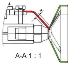
Fig. 11
Fig. 13
Fig. 14
Fig. 17
4.8 Circuito olio
1 Elettrovalvola
natural_image
Mechanical assembly diagram showing a component with red arrows indicating direction, no visible text or symbols4.8.2.2 Sistema monotubo (optional)
Fig. 22
| H (m) | Lunghezza tubo (m) | ||
| ∅6 mm ∅8 mm ∅10 mm | |||
| 0,5 19 60 | 100 | ||
| 1 21 66 | 100 | ||
| 1,5 23 72 | 100 | ||
| 2 25 79 | 100 | ||
| 2,5 27 85 | 100 | ||
| 3 29 91 | 100 | ||
| 3,5 31 98 | 100 | ||
| ---- | |||

ATTENZIONE
- X < 20m
natural_image
3D mechanical assembly diagram showing internal components with no visible text or symbols
AVVERTENZA
É obbligatorio:
Fig. 30
natural_image
Mechanical assembly diagram showing a motor and a gear component with a red arrow indicating motion (no text or symbols present)Fig. 32
natural_image
Mechanical assembly component with labeled part (1), no visible text or symbols on the main bodyFig. 36
natural_image
Technical diagram showing a mechanical component with cross-sectional view and top view, labeled Fig. 47 (no text or symbols on the diagram itself)natural_image
Mechanical assembly diagram showing a motor or gear mechanism with no visible text or symbolsFig. 51
natural_image
Technical diagram of an industrial electrical switchgear assembly (no text or labels visible)Fig. 52
natural_image
3D rendering of a gray industrial device with labeled TSB component (no readable text or symbols beyond label)Fig. 54
SAFETY WARNINGS AND REGULATIONS

WARNINGS
- After having removed the packaging make sure that the product supplied is integral and complete in all its parts. If this is not the case, please contact the Dealer who sold the appliance.
- The appliance must be used as intended by SIME who is not responsible for any damage caused to persons, animals or things, improper installation, adjustment, maintenance and improper use of the appliance.
- In order to ensure optimal appliance operations SIME recommends that maintenance and checks are carried out ONCE A YEAR.
- It is recommended that all operators read this manual carefully in order to use the appliance in a safe and rational manner.
- This manual is an integral part of the appliance. It must therefore be kept for future reference and must always accompany the appliance in the event the appliance is transferred or sold to another Owner or User or is installed on another system.

WARNINGS
- Installation and maintenance of this appliance must be carried out by a qualified company or by a professionally qualified technician in accordance with the instructions contained in the manual. Once the work is complete, the company or technician will issue a declaration of conformity with national and local technical standards and legislation in force in the country where the appliance will be used.
- Any repairs on the appliance must be carried out solely by professionally qualified personnel, using original spare parts only. Failure to comply with these instructions can jeopardise the appliance's safety and void the warranty with immediate effect.
- Fonderie SIME S.p.A. reserves the right to make improvements to its products at any time without prior notice, without compromising their essential characteristics. The graphic illustrations and/or images in this document may show optional accessories that vary according to the country in which the appliance is used.
RESTRICTIONS

IT IS FORBIDDEN
- To allow children under the age of 8 to use the appliance. The appliance can be used by children no younger than 8 years old, by people with physical or cognitive disabilities, and by people lacking experience or the necessary knowledge, provided that they are supervised or have been instructed on how to use the appliance safely and that they understand the risks associated with it.
- To allow children to play with the appliance.
- To allow unsupervised children to perform user maintenance and cleaning.
- To use electrical devices or appliances such as switches, electrical appliances etc if you can smell fuel. If this should happen:
- open the doors and windows to air the room;
- close the gas isolation device;
-promptly call for professional assistance. - To touch the appliance with bare feet or with any wet part of the body.

IT IS FORBIDDEN
- Do not carry out any technical intervention or cleaning operation unless the appliance has been disconnected from the mains power by setting the system to "OFF", and before shutting off the supply of fuel and of water from the hydraulic circuit.
- To modify the safety or adjustment devices without authorization and instructions from the manufacturer.
- To pull, detach or twist the electrical cables coming out of the appliance even if the appliance is disconnected from the mains power supply.
- To block or reduce the size of the ventilation openings of the room where the appliance is installed, if present.
- To leave containers with flammable substances in the room where the appliance is installed.
- To dispose of the packaging material irresponsibly as it could be dangerous. Packaging must be disposed of as specified by the legislation in force in the country where the appliance will be used.
RANGE
| BURNER MODEL | SIME CODE |
| SIME FUEL 25 EV (vers. std) 8118500 | |
| SIME FUEL 35 EV (vers. std) 8118501 | |
| SIME FUEL 25 EV (vers. HE) 8118502 | |
| SIME FUEL 35 EV (vers. HE) 8118503 |
COMPLIANCE
Our company declares that the FUEL EV burner conforms to the essential requirements of the following directives:
- Low Voltage Directive 2014/35/EU
- Electromagnetic Compatibility Directive 2014/30/EU
- Ecodesign Directive 2009/125/EC
- Directive 2006/42/EC (Machinery Directive)
- Directive 2011/65/EU (RoHS Directive)
CE
SYMBOLS

WARNING
Indicates potentially dangerous situations and operations that could damage the appliance or nearby objects and cause serious injury, death or health risks in the long run to people if not treated or carried out correctly.

ELECTRICAL HAZARD
Indicates a dangerous situation that can cause serious injury, death or health risks in the long run, caused by electrical power, if not treated carefully and correctly.

IT IS FORBIDDEN
To indicate actions which MUST NOT BE carried out.

CAUTION
This symbol indicates important information that must be taken into account.

DANGER: FLAMMABLE MATERIAL
Indicates a dangerous situation that can cause serious injury, death or health risks in the long run, due to the presence of flammable substances near the equipment, if not treated carefully and correctly.

WARNING: HOT SURFACE
Indicates potentially dangerous situations due to the presence of very hot surfaces that can cause minor and light injuries or burns if not treated correctly.
Dear Customer,
thank you for purchasing a SIME product.
The model you have chosen is a high-performance product stemming from a technologically advanced idea, is highly reliable and features an excellent construction quality.
We recommend entrusting the management and maintenance of this appliance to expert personnel and using only original spare parts, when necessary.
This manual contains important guidelines and suggestions that should be observed to simplify its installation and obtain the best possible use from the appliance.
SPECIFIC WARRANTY
FUEL EV burners are covered by LEGAL WARRANTY and by a possible WARRANTY EXTENSION, which will be proposed by the Technical Support Service in your area and will take effect from the date on which the Service itself validates it.
DISPOSAL OF THE EQUIPMENT
At the end of their life span, the appliance and electrical and electronic devices coming from households or classifiable as household waste must be delivered to appropriate waste collection systems, in accordance with the law and with Directive 2012/19/EU. This product was designed and manufactured for minimising its impact on the environment and on human health, but it contains components that could be detrimental if managed improperly. The symbol (crossed-out wheelie bin) depicted here and also appearing on your appliance means that the appliance at the end of its life must be managed in accordance with the law and treated as electrical and electronic waste. Before delivering the appliance for its disposal, consult the applicable provisions of the laws in force in the country where the appliance is used and get information on the authorised waste disposal facilities by contacting the relevant local offices.
TABLE OF CONTENTS
1 SAFETY 38
1.1 General information 38
1.2 Intended use 38
1.3 Primary dangers 38
2 GENERAL 39
2.1 Description of the burner 39
2.3 Identification 39
2.2 Supply....39
2.4 Structure 40
2.4.1 Burner structure.... 40
2.4.2 Combustion head structure 41
2.5 Operating logic (two-pipe system) 41
2.6 Electrical control and command equipment.....42
2.6.3 Safety function 42
2.6.1 Operating function 42
2.6.2 Controlled stoppage 42
3 SPECIFICATIONS 43
3.1 Wiring diagram 44
4 INSTALLATION 45
4.1 Receiving the product 45
4.2 Dimension and weights....45
4.3 Installation room 46
4.3.1 Fume exhaust system.... 46
4.4 Assembly/adjustment tools 46
4.5 Preliminary checks prior to mounting the burner .... 46
4.6 Mounting the burner 46
4.7 Removing and mounting the cover 47
4.8 Oil circuit 47
4.8.1 Hydraulic diagram of the fuel pump ..... 48
4.8.2 Fuel pump 48
4.8.3 Two-pipe systems.... 49
4.8.4 Electrical connections to the boiler.....50
4.9 Removing the burner 50
5 COMMISSIONING 51
5.1 Preliminary operations 51
5.2 Factory calibration....51
5.3 Initial start-up of the burner....52
5.4 Adjustment....53
5.5 Pump pressure adjustments 53
5.6 Checking the pump's negative pressure 53
5.7 Commissioning adjustments 54
5.7.1 Setting and measured values 55
6 MAINTENANCE 56
6.1 Adjustments....56
6.2 Removing the burner 56
6.2.1 Cleaning the impeller.... 57
6.2.2 Replacing the coil 58
6.2.3 Cleaning and replacing the combustion head....59
6.2.4 Checking the position of the diffuser ..... 59
6.2.5 Checking he position of the combustion head . . . 60
6.2.6 Checking the position of the electrodes . . . 60
6.2.7 Cleaning the pump filter.... 60
6.2.8 Checking the pump rotation.... 60
6.2.9 Scheduled replacement of worn components ... 61
6.2.10 Replacing the capacitor 61
7 POSSIBLE FAULTS AND SOLUTIONS 62
7.1 Troubleshooting....63
8 APPENDIX 65
8.1 Use of biodiesel 65
8.2 Important suggestions for using biofuel blends.....65
8.2.1 Introduction.... 65
8.2.2 General information and instructions ..... 65
1.1 General information
The instructions for installing, commissioning and servicing the burner are addressed to technicians of professional heating companies enabled to perform the aforementioned activities. The instructions contain indications and information for moving, handling, activating, adjusting, servicing and removing the appliance and disposing of its components at the end of their life. Conformity to the specified information and the regulations in force are the prerequisites for a safe job.
The burner cannot be installed outdoors, unless it is installed in a boiler suitably designed for this purpose, therefore also equipped with a control panel and accessories suitable for managing the anti-freeze function.
This manual must be kept near the product where it can be consulted by all operators who intervene in the activities.

WARNING
The installation, commissioning and maintenance activities must be entrusted only to personnel of specifically qualified companies of the sector.
1.2 Intended use
The burner is a heat source for space heating and domestic hot water production systems, in which the heat-transfer fluid is water.
Any additional and broader application goes beyond the specific intended use.
To prevent risks, the burner can only be used:
- for its specific intended use;
– in the appropriate safety conditions; - by observing the installation, commissioning and maintenance instructions;
- in conformity to the maximum and minimum operating values;
– in conformity to all the necessary maintenance activities; - by immediately solving any malfunctions that can jeopardise safety;
- by keeping in a legible condition any notes and precautions attached to the product;
1.3 Primary dangers
The following indications concern “residual risks” which must be pointed out so that the owner, manager and operators can fully understand them and adopt a responsible approach.
They derive from the risk analysis conducted by the Research & Development staff as imposed by the European standard EN 267 and the directives in force relevant to the sector (Machinery, LVD, EMC directives).

ELECTRICAL HAZARD
- Contact with live electrical components can lead to serious accidents.
- Only professionally trained and qualified personnel can intervene on the electrical system.
- Prior to any intervention, disconnect the power supply to the system through the main switch, check that there is no voltage and verify that the system cannot restart.
- If the product's electrical insulation is damaged, intervene promptly to restore its correct rating.

WARNING: HOT SURFACE
- Contact with high-temperature components can cause superficial burns of varying intensity.
- Operators must wear adequate clothing and personal protective equipment.
- They must ensure that all the components are at room temperature before carrying out any maintenance operations.

LOSS OF FUEL
- Loss of fuel can trigger fires.
- It may be dangerous if inhaled and can cause dermatitis.
- If oil mist forms, use a protective face mask with a filter for organic vapours and a particulate filter.
- Promptly intervene by removing the cause of the loss and, if it is related to a maintenance activity, use appropriate personal protective equipment.
2 GENERAL
2.1 Description of the burner
SIME FUEL EV is a new generation single-stage burner that runs on diesel. Its innovative combustion head ensures low emissions of NOx and of CO within the emission limits specified in Regulation (EC) No. 813/2013 (ErP).
The burner uses functional components that, besides guaranteeing long-lasting operation, ensure easy installation, adjustment and maintenance. The high-performance electrical components keep the consumption levels low.
The ventilation system guarantees high efficiency and, thanks to the thermostatic pre-heater, starting up the device with the boiler body cold does not create any problems. SIME FUEL EV burners operate reliably even in case of persistent or gusty wind, they will ignite effectively and with the smoke index under control.
Their compact dimensions, low noise level and ease of installation make them suitable for being applied on boilers fitted in domestic environments.
2.2 Supply
The SIME FUEL EV burner includes the following equipment:
- °1 flange with fixing bolt
- °1 seal for the flange
- °2 flexible pipes L=1200 mm
- °2 G 3/8 - 1/4 nipple (for flexible oil pipes)
- °4 screws with captive washer for fastening the flange to the boiler
- °1 7-pin plug (mounted on the burner) (*)
- °1 4 mm Allen key
- n°1 control template (mounted on the burner)
- °1 diesel filter
2.3 Identification
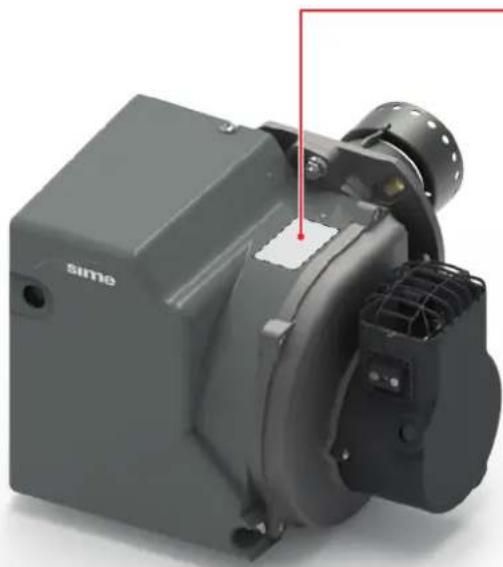
Check the burner's identification label ("Fig. 1").
natural_image
3D rendering of a gray industrial machine component with mounting bracket and control panel (no visible text or symbols)A Burner code
B Week and year of manufacture
c Burner model
D Burner power output (factory setting)
E Burner capacity (factory setting)
F Power supply
G Protection rating
H Electrical consumption
1 Types of fuel used
J Serial number
(A)
[C]
(F)
(G)
[J]
![Sime Fonderle Sime S.p.A. Via Garbo, 27 -Legnago (VR) ITALY CE ErP 3146947|SN2000041469|SL0056 00105525|DH28/10/2020 14.43.13 [kW] [kg/h] 1N-230 V ~ 50 Hz IP40 FUEL Visc. @ 20 °C 1,6-6 mm²/s WEIGHT 8,0 kg 2000041469 Made in Italy (B) (D) (E) (H) (I)](/content/2026/05/943289/images/d9aef1893b3838cccb7f7f31613a2c024be2ba6d04b67d91522f27a504309d8d.jpg)
Fig. 1

WARNING
It is strictly forbidden to remove the identification label.
Tampering with, removing or the absence of the burner's data plate, or whatever prevents the clear identification of the burner itself, could complicate installation interventions and/or maintenance activities.
2.4 Structure
2.4.1 Burner structure
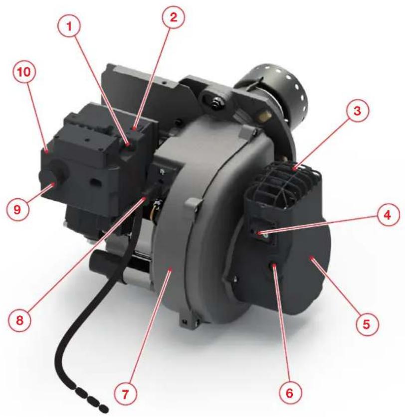
1 Heat request LED (green)
2 Socket/plug for electrical connection with the boiler
3 Air intake grille
4 Air regulation valve
5 Air suction casing
6 Air shutter adjustment indicator
7 Impeller housing body
8 Flame detection sensor
9 Unlock button and lock-out indicator light (red)
10 Electrical control and command equipment
Fig. 2
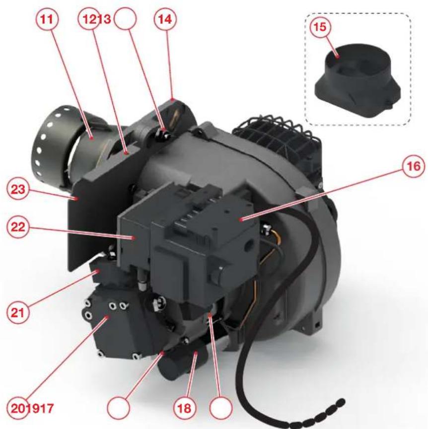
11 Combustion head
12 Cowling fixing screw
13 Burner fixing screw
14 Burner flange (supplied)
15 Adapter for external air intake pipe (optional)
16 7-pin plug
17 Electric motor for pump and fan
18 Capacitor
19 Foot
20 Diesel pump
21 Diesel valve
22 Ignition transformer
23 Front panel
Fig. 3
2.4.2 Combustion head structure
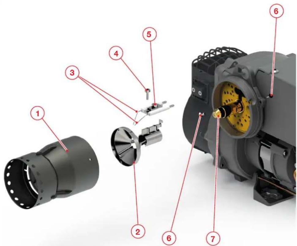
1 Nose
2 Flame stabilisation disc
3 Electrode assembly
4 Diffuser fixing screw
5 Electrodes fixing screw
6 Nose fixing screw
7 Nozzle
Fig. 4
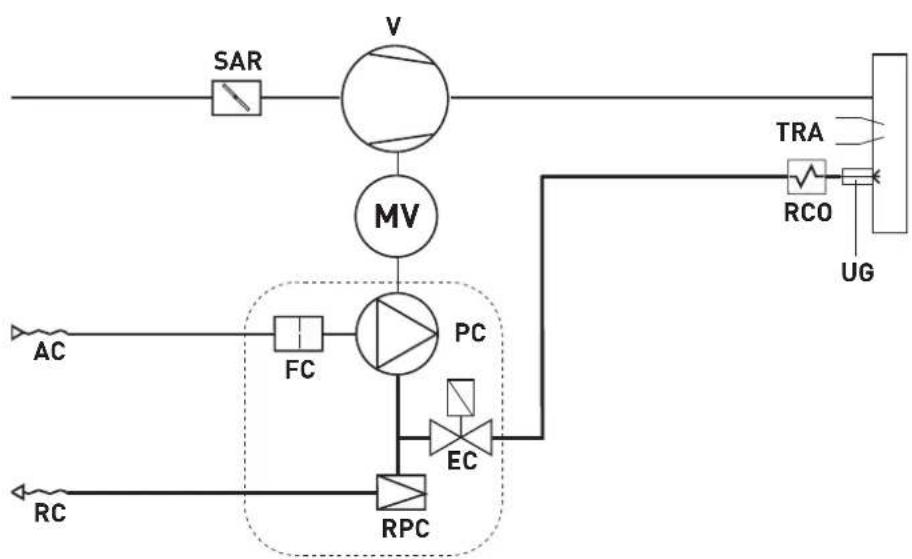
2.5 Operating logic (two-pipe system)
flowchart
graph TD
    A["AC"] --> B["FC"]
    B --> C["PC"]
    C --> D["EC"]
    D --> E["RCO"]
    E --> F["UG"]
    G["SAR"] --> H["V"]
    H --> I["MV"]
    I --> J["RPC"]
    J --> K["RC"]
    style A fill:#f9f,stroke:#333
    style B fill:#ccf,stroke:#333
    style C fill:#cfc,stroke:#333
    style D fill:#fcc,stroke:#333
    style E fill:#cff,stroke:#333
    style F fill:#ffc,stroke:#333
    style G fill:#fff,stroke:#333
    style H fill:#fff,stroke:#333
    style I fill:#fff,stroke:#333
    style J fill:#fff,stroke:#333
    style K fill:#fff,stroke:#333
MV Fan motor
TRA Ignition transformer
EC Diesel valve
V Fan
PC Fuel pump
SAR Air shutter
RPC Fuel pressure regulator
AC Fuel suction
FC Fuel filter
UG Nozzle
RCO Fuel heater
RC Fuel return
Fig. 5
2.6 Electrical control and command equipment
The EBR-M14 command and control electrical equipment controls and monitors the burner's operation. The microprocessor controls the programme's sequence and guarantees maximum stability of the cycle times, regardless of any fluctuations in the supply lines or of the room temperature. The control unit is made with materials that guarantee protection against the potential consequences caused by open flames. Whenever the supply voltage drops below its minimum rated level (70 ± 8 V), the control unit locks out, even if no error signal appears. It switches back on after the supply voltage rises again above (190 ± 8 V).
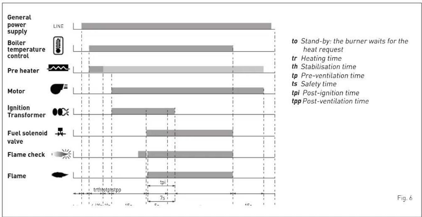
2.6.1 Operating function
- If there is a heat request (green LED lit), the command and control unit will start the programme's sequence.
- The heater heats the diesel in the oil line.
- When the optimal temperature is reached, the motor starts, the ignition transformer activates and the 15-second pre-ventilation phase starts.
- During the pre-ventilation phase, the burner is monitored through the flame signal.
- Once the pre-ventilation phase terminates, the diesel sole-noid valve opens, the flame ignites and the burner starts.
- The ignition transformer remains engaged for the entire duration of the post-ignition phase.
2.6.2 Controlled stoppage
Controlled stoppage occurs if:
- the boiler thermostat interrupts the heat request;
- the oil solenoid valve closes and the flame goes out;
- the 15-second (factory-set time) post-ventilation cycle starts, after which the motor stops;
- the burner enters the stand-by mode pending a new heat request.
2.6.3 Safety function
A safety shutdown occurs if:
- during the pre-ventilation phase there is a flame signal (flame monitoring);
- the flame has failed to ignite within the safety interval (5s from the opening of the fuel solenoid valve).
A safety shutdown is signalled by the lock-out indicator light (lit steady red).
The operating conditions can only be restored (reset) once the cause of the lock-out has been eliminated and the reset button (9) has been pressed, as illustrated in "Fig. 2".
bar
| Component | Duration (s) | | :--- | :--- | | General power supply | 15 | | Boiler temperature control | 10 | | Pre heater | 7 | | Motor | 12 | | Ignition Transformer | 6 | | Fuel solenoid valve | 8 | | Flame check | 4 | | Flame | 9 |3 SPECIFICATIONS
| SIME FUEL | |||||
| SIME FUEL 25 EV (vers. std) | SIME FUEL 35 EV (vers. std) | SIME FUEL 25 EV (vers. HE) | SIME FUEL 35 EV (vers. HE) | ||
| Heat output set in the factory(1) | kW | 27 34,8 27 34,8 | |||
| kcal/h | 23,220 29,928 23,220 | 29,928 | |||
| Heat capacity set in the factory(1) | kg/h | 2,25 2,9 2,25 2,9 | |||
| Fuel(2) | Diesel, viscosity 1.6–6 mm ^2 /s a (Hi=12.01 kWh/kg) | ||||
| NOx emissions | < 120 mg/kWh[in accordance with Regulation (EC) No. 813/2013 and the EN 267:2020 standard Class 4] < 120 mg/kWh[in accordance with Regulation (EC) No. 813/2013 and the EN 267:2020 standard Class 4] | ||||
| Control and command equipment EBR - M14 R 15-15 | |||||
| Flame sensor | EBR FTEB [Black] | ||||
| Ignition transformer | Fida 2P 26 kV pp-35 mA rms | ||||
| Fuel oil pump | Suntec ALV 35A | ||||
| Pump coil | 871 T80 | ||||
| Electric motor | EBR 90 W, 2800 rpm | ||||
| watt | 90 | ||||
| Capacitor | Inco 4 μF, TEKNO 45T (T = top series) | ||||
| Power supply | 1 / 230 / 50 Ph / V / Hz | ||||
| Power input (during operation) (+/- 5W) | W | 183 | 181 | ||
| Electrical protection | IP | IP40 | |||
| Sound pressure level | dB(A) | 65 | |||
| Storage room temperature | °C | -20 ... +70 | |||
| Operating temperature | °C | -10 ... +60 | |||
(1) Reference conditions: Room temperature 20 °C – Barometric pressure 1013 mbar – Altitude 0 m.a.s.l..

CAUTION
^[2] The burner is suitable for use with diesel containing a biofuel blend of up to 10%. A minimum requirement for biofuel blends (up to 10%) is that they be obtained with diesel in accordance with the applicable standards and in conformity to the local regional regulations.
If the biofuel contains an organic blend above 10%, contact the manufacturer.
3.1 Wiring diagram
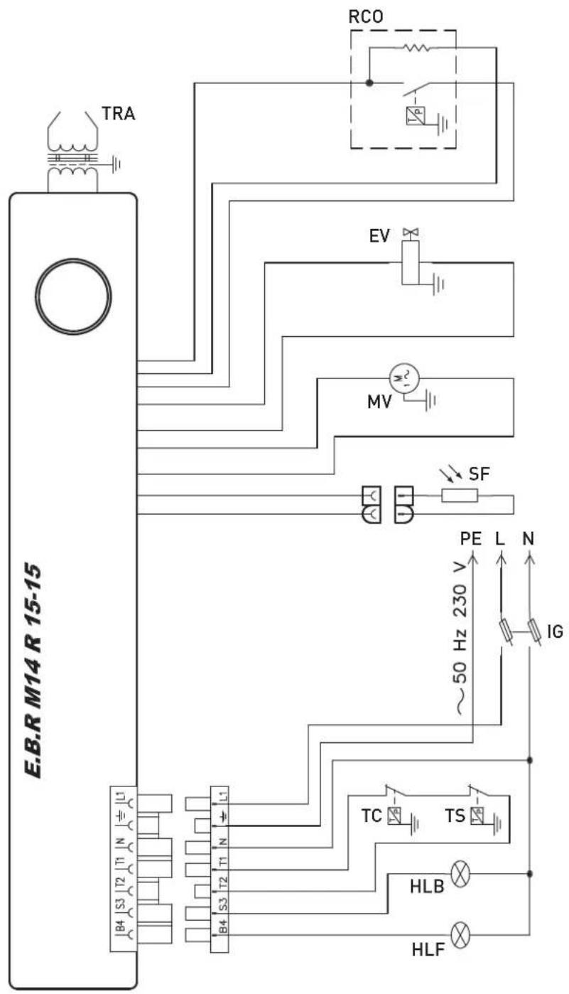
SF Flame sensor
MV Fan motor
TRA Transformer
RCO Fuel heater
EV Diesel solenoid valve
IG Main switch with fuse
TC Boiler thermostat
TS Safety thermostat
HLF Operation lamp
HLB Lock-out lamp
Fig. 7
4 INSTALLATION
4.1 Receiving the product
The SIME FUEL EV and FUEL HE EV burners are supplied in a single cardboard pack protected by a nylon bag.
The packaging includes the following material:
- user, installation and servicing instructions;
- warranty certificate;
- flexible pipes;
- fuel filter.

CAUTION
The appliance must only be installed by the SIME Technical Service or by qualified professionals who MUST wear suitable protective safety equipment.
4.2 Dimension and weights
| Code Model | Weight (kg) | ||
| net with | packaging | ||
| 8118500 SIME FUEL 25 EV (vers. std) 8,2 10,1 | |||
| 8118501 SIME FUEL 35 EV (vers. std) 8,2 10,1 | |||
| 8118502 SIME FUEL 25 EV (vers. HE) 8,2 10,1 | |||
| 8118503 SIME FUEL 35 EV (vers. HE) 8,2 10,1 | |||
All the measurements are in millimetres.
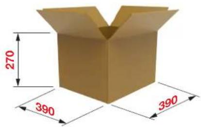
Fig. 8
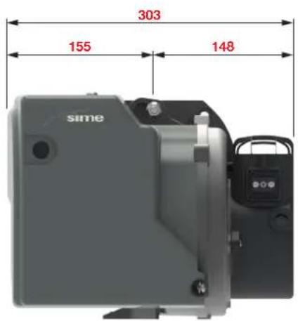
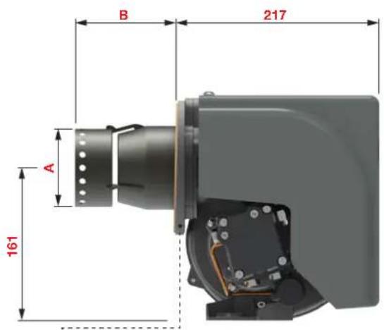
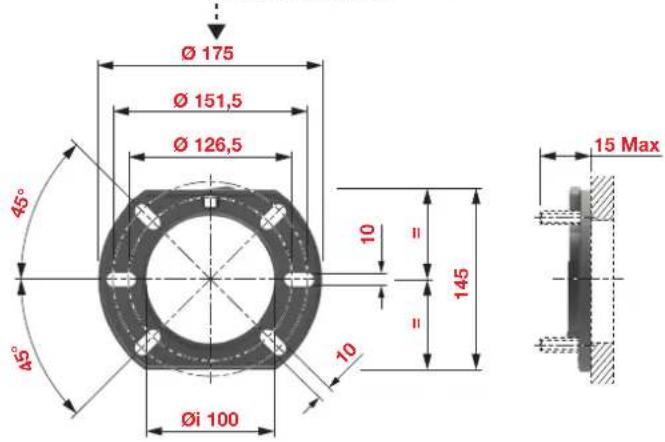
| Model A B | ||
| SIME FUEL 25 EV ∅ 72 | 87 | |
| SIME FUEL 35 EV ∅ 83 | 104 |
Fig. 9
4.3 Installation room
Before installing the product, make sure that the room of installation meets the following requirements:
- Operating temperature from +5°C to +45°C;
- Dry, not subject to frost, well ventilated;
- Not subject to heavy dust build-up;
- Not subject to high humidity;
- Free of atmospheric pollutants due to halogenated hydrocarbons (contained in solvents, adhesives, aerosol, etc.);
- Free of atmospheric pollutants due to sulphuric gases;
- Not subject to vibration.

WARNING
Highly flammable materials or liquids can catch fire.
- Do not use or store explosive or highly flammable substances (such as petrol, paint, paper, wood) in the area where the appliance is installed.
4.3.1 Fume exhaust system
Before installing the product, make sure that the exhaust system for combustion by-products is suitably designed in relation to the type of generator to be installed and in accordance with the applicable standards and regulations.
4.4 Assembly/adjustment tools
The most common and frequent operations on the burner are carried out simply with the aid of an Allen key supplied.
This key can be used to:
- Remove the cover
- Remove the nose
- Adjust the electrodes
- Adjust the fuel pressure
- Adjust the air
- Perform work on the pump
4.5 Preliminary checks prior to mounting the burner
Before mounting the burner on the boiler:
- check the gap between the electrode tips (2 mm) (use the template supplied with the burner);
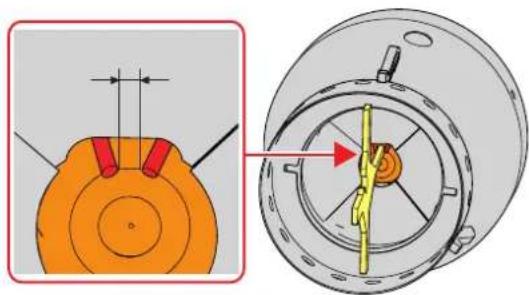
natural_image
Technical diagram showing a mechanical component with cross-sectional view and top-down view (no text or symbols)Fig. 10
- use a screwdriver to remove the screws (1) and pull out the nose (2) as described in the procedure set out in the "Cleaning and replacing the combustion head" paragraph then check the position of the electrodes while ensuring that they are centred as shown in "Fig. 11".
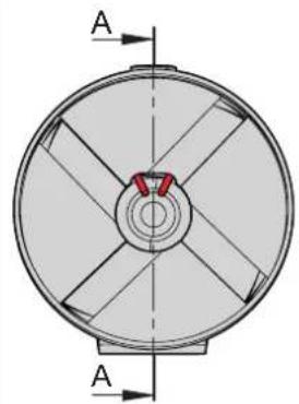
natural_image
Technical diagram of a circular mechanical component with radial slots and central hub, labeled 'A' at both ends (no text or symbols on the component itself)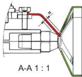
Fig. 11
4.6 Mounting the burner

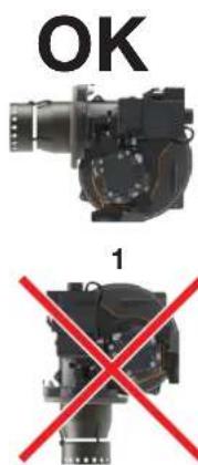
WARNING
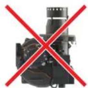
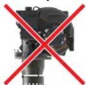
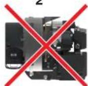
- Install the burner on the boiler by observing the positions illustrated in "Fig. 12".
- The installations 2, 3 and 4 are forbidden for safety reasons.
3
2
4
Fig. 12
To mount the burner on the boiler:
- couple the seal (1) and the flange (2), both supplied with the product;
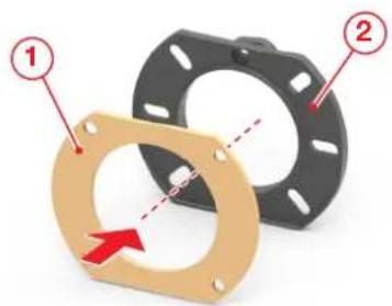
Fig. 13
- position the flange [2], with the fixing screw [3] on top and lock it with the nuts [4] provided;
- tighten the nuts (4) adequately diagonal-wise;
- insert the combustion head (5) of the burner inside the flange (2);
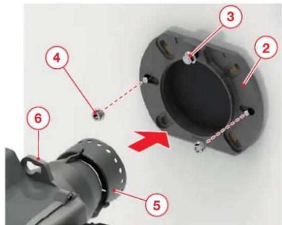
Fig. 14
- turn the burner slightly, first towards the right then towards the left, to properly position the fixing screw (3) in its housing (6);
- press the burner against the boiler and tighten the fixing screw (3) to lock it in place;
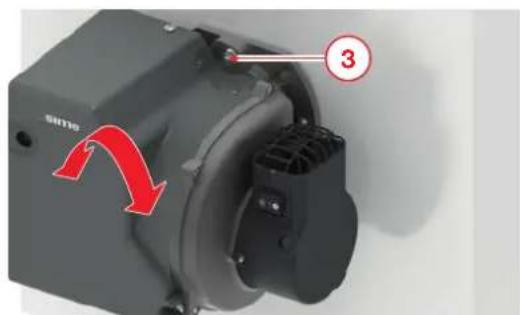
Fig. 15
- for applications with suction from the outside, remove the intake grille (7) and replace it with the adapter for mounting the external pipe (8) code 6290502 (optional)
- insert the air intake pipe (9) and secure it using a pipe clamp (10), both not supplied.
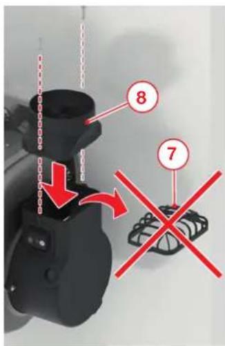
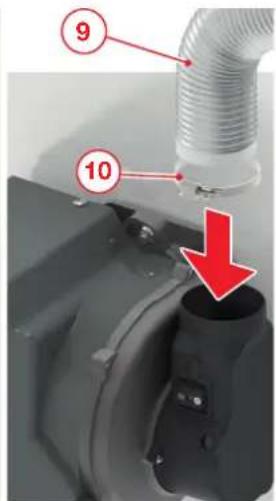
Fig. 16
4.7 Removing and mounting the cover
- Remove the cover by loosening the two screws (1) and then pull the cover out (2) while taking care not to damage it.
- Mount the component back on by performing the above steps in reverse order.
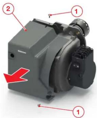
Fig. 17
4.8 Oil circuit
The fuel tank and the piping layout must be made in such a way that the temperature of the diesel entering the burner is equal to at least +5°C. The system MUST be topped up with the burner switched off. It should be kept off subsequently for around 1 hour to ensure degassing of the fuel and to allow any suspended particles to settle.
When the burner is replaced, replace the fuel filter as well.

LOSS OF FUEL
In case of accidental fuel loss:
- Promptly stop the burner
- Close the fuel valves
- Ventilate the room
- Promptly report the problem to the qualified Technical Service and have the necessary repairs carried out.
4.8.1 Hydraulic diagram of the fuel pump
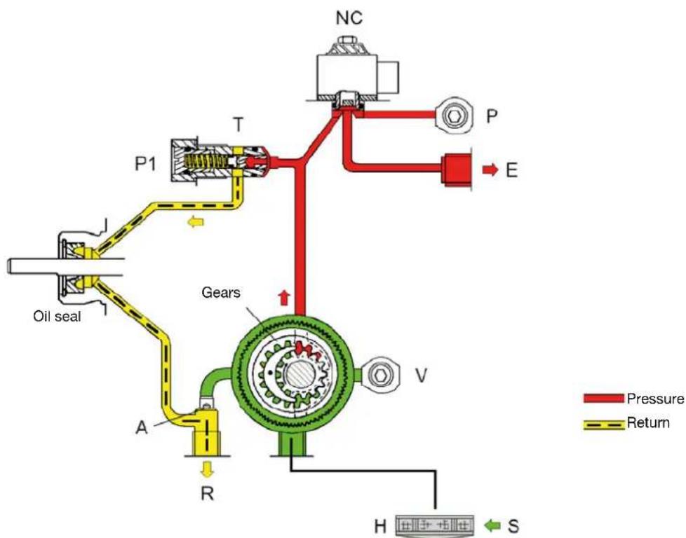
flowchart
graph TD
    A["Oil seal"] --> B["P1"]
    B --> C["T"]
    C --> D["Gears"]
    D --> E["V"]
    E --> F["R"]
    F --> G["H"]
    G --> H["S"]
    H --> I["E"]
    I --> J["P"]
    J --> K["NC"]
    style A fill:#f9f,stroke:#333
    style B fill:#ccf,stroke:#333
    style C fill:#cfc,stroke:#333
    style D fill:#fcc,stroke:#333
    style E fill:#cff,stroke:#333
    style F fill:#ffc,stroke:#333
    style G fill:#cfc,stroke:#333
    style H fill:#fcc,stroke:#333
    style I fill:#ffc,stroke:#333
    style J fill:#cfc,stroke:#333
    style K fill:#fcc,stroke:#333
A By-pass screw
E Nozzle
H Filter
NC Valve
P Pressure gauge fitting
P1 Pressure adjustment screw
R Return
S Inlet
T Pressure regulator
V Vacuum gauge fitting
Fig. 18
4.8.2 Fuel pump
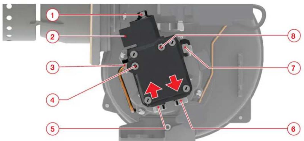
1 Solenoid valve
2 Solenoid valve connection
3 Fuel conveying pipe
4 Vacuum gauge fitting
5 Inlet
6 Return
7 Fuel pressure regulator
8 Pressure gauge fitting
Fig. 19
4.8.2.1 Two-pipe system (standard)
The pump is configured for two-pipe operation.
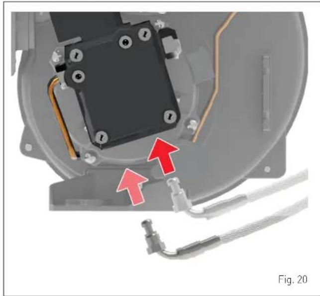
natural_image
Mechanical assembly diagram showing a component with red arrows indicating direction, no visible text or symbols4.8.2.2 Single-pipe system (optional)
If a single-pipe system is used, a single flexible pipe for the oil is required.
For this type of connection, it is necessary to remove the by-pass grub screw (10) (using a 4 mm Allen key) and fit the plug (11) (5 mm Allen key) along with its seal.
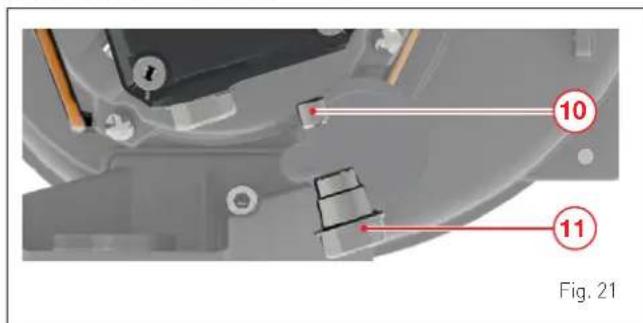

WARNING
Before starting the burner, verify that the return line is free. Any obstruction can damage the pump's sealing device.

WARNING
- Only certified supply lines must be used.
- A single flexible pipe is required for single-pipe systems.

CAUTION
There is an internal filter and a pressure regulator integrated in the pump. The vacuum gauge must be connected before starting up the burner.
4.8.3 Two-pipe systems
Burner lower than the tank
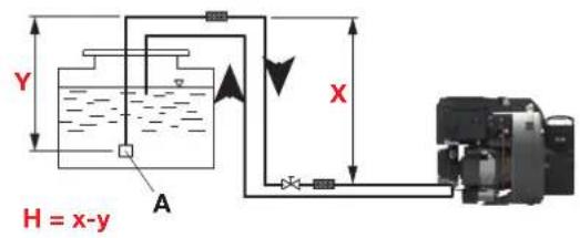
Fig. 22
| H (m) | Lunghezza tubo (m) | ||
| ∅6 mm ∅8 mm ∅10 mm | |||
| 0,5 19 60 | 100 | ||
| 1 21 66 | 100 | ||
| 1,5 23 72 | 100 | ||
| 2 25 79 | 100 | ||
| 2,5 27 85 | 100 | ||
| 3 29 91 | 100 | ||
| 3,5 31 98 | 100 | ||
| ---- | |||

WARNING
- X < 20m
- A = Bottom valve, which must be kept as low as possible to prevent cavitation. In any case, Y < 4m.
Burner higher than the tank
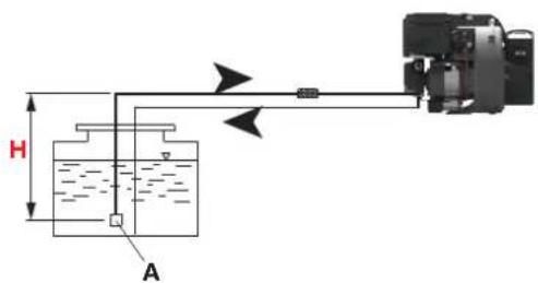
Fig. 23
| H (m) | Lunghezza tubo (m) | ||
| ∅6 mm ∅8 mm ∅10 mm | |||
| 1 13 41 9 | 9 | ||
| 1,5 11 34 84 | |||
| 2 9 28 68 | |||
| 0,5 | 7 22 53 | ||
| 1 5 15 37 | |||
| 1,5 | - | 9 22 | |
| 2 | --- | ||
4.8.4 Electrical connections to the boiler
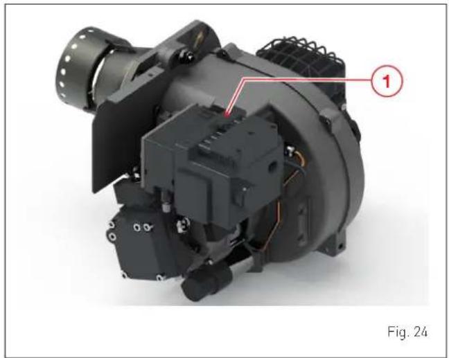
The SIME FUEL EV burner is fitted with a 7-pole female/male connector (1) for making the electrical connections to the boiler's control panel.
The electrical connections must conform to the wiring diagram provided by the manufacturer of the boiler and must be made by the installer.
- The electrical system must be arranged by qualified personnel in accordance with the regulations in force in the country of destination. Refer to the wiring diagrams.
- Check that the supply voltage matches the value shown on the wiring diagram and on the data plate.
- Burner fuse: 3 A.
- Use flexible cables in conformity to the EN 60 335-1 standard. Ensure a proper earthing connection.
- The cross-sectional dimensions of the cabling must be at least 1mm2 (in any case, refer to the standard and the local regulations).
natural_image
Mechanical assembly component with labeled part (1) and figure number (Fig. 24), no readable text or symbols beyond labels
CAUTION
It is compulsory:
- To mount an omnipolar residual-current circuit breaker conforming to EN standards that allows for completely disconnecting the system in overvoltage category III conditions (that is, with a gap of at least 3 mm between the open contacts).
- Respect the connections L (Live) - N (Neutral). It is compulsory:
- To connect the earth wire to an effective earthing system. The manufacturer shall not be held liable for damages caused by failure to earth the appliance or failure to observe the information provided in the wiring diagrams.

IT IS FORBIDDEN
To use the water pipes to earth the appliance.
4.9 Removing the burner
When it is necessary to remove the burner from the boiler:
- shift the main switch of the system and of the boiler to "OFF";
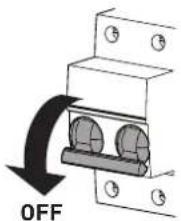
Fig. 25
- close the fuel shut-off valves mounted upstream of the burner;
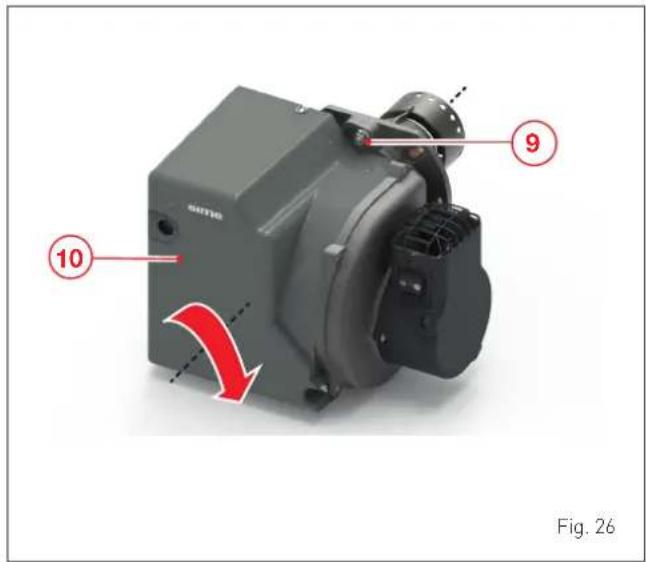
- loosen the nut (9) fastening the burner to the boiler, turn the burner (10) slightly towards the right and remove it from the boiler.
NB.
If the burner is extracted from the boiler to perform routine or extraordinary maintenance, refer to the specific chapter "MAIN-TENANCE".
5 COMMISSIONING
5.1 Preliminary operations

CAUTION
The commissioning and initial start-up operations must be carried out ONLY by professionally qualified personnel who must follow the indications provided in this manual and in the manual of the relevant boiler. The operator must wear personal protective equipment.
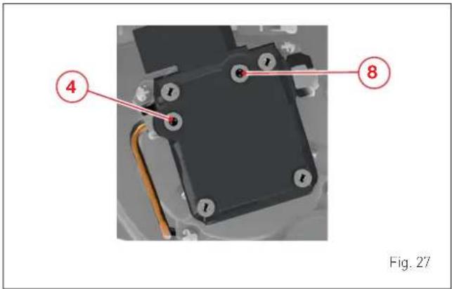
Prior to commissioning the appliance, remove the screws (4) and (8) and install a vacuum gauge and a pressure gauge respectively.
Then verify that:
- There is sufficient fuel in the tank.
- The fuel, thermal system and water circuit valves are open.
- The electrical connections have been made correctly.
- The exhaust pipes for combustion by-products have been arranged correctly.
-
In case of TYPE B installations, the vents are adequately sized in relation to the installed power and the combustion air inlet of the burner is free (without splits).
-
The fume exhaust system has been made correctly.
- The system has been correctly pressurised and all the expansion vessels have been pre-charged.
- The control, command and safety devices are present.
5.2 Factory calibration
All the burners are adjusted and tested in the factory according to the data shown in the table and in the reference conditions specified below.
| Burner | Burned power +/- 4% | Nozzle (Danfoss) | Pump pressure* | Air shutter adjustment | ||
| Model kW Kg/h GPH Spray bar | mm (+/-0,1) | |||||
| SIME FUEL 25 EV (vers. std) 27 2 | 25 0,55 60°H | 12,0 3,8 +/- 0,2 | ||||
| SIME FUEL 35 EV (vers. std) | 34,8 2,90 | 0,65 60°H 12,0 5 | 7 +/- 0,2 | |||
| SIME FUEL 25 EV (vers. HE) | 27 2,25 | 0,55 60°H 12,0 3,5 +/- 0,2 | ||||
| SIME FUEL 35 EV (vers. HE) | 34,8 2,90 | 0,65 60°H 12,0 5 | 5 +/- 0,2 | |||
(*) The pump pressure is measured after an operating interval of 5 min.
Reference conditions
- Fume exhaust system: diameter 80 mm / length 1.5 m
- Room temperature: 20°C +/-5
- CO2 = 12.5% ± 0.2.
- Altitude 0 m.a.s.l..
When the burner is installed at altitudes up to maximum 1300 m.a.s.l., due to the lower air density, the factory adjustments for the burner must be modified as follows:
- Keep the nozzle mounted in the factory
- Do not vary the position of the combustion head
- Gradually reduce the pump pressure to reduce the fuel flow rate
- Adjust the air shutter by taking the following readings:
- CO2 (%)
- CO (ppm)
- NOx (ppm)
- Bacharach index
- Flue gas temperature.
If the outdoor temperature is such that it may influence combustion, we recommend adjusting the CO2 according to the following diagram.
During winter, set a lower CO 2 value. In the warmer periods of the year, set a higher CO 2 value.
1% increase of Co _2 every 20°C of room temperature increase.
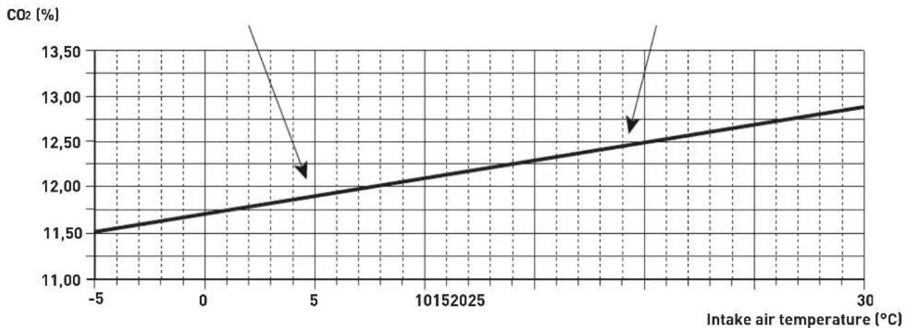
line
| Intake air temperature (°C) | CO2 (%) | | ---------------------------- | ------- | | -5 | 11.50 | | 0 | 11.75 | | 5 | 12.00 | | 10 | 12.25 | | 20 | 12.50 | | 30 | 12.75 |Fig. 28

WARNING
All operations must be carried out exclusively by the Sime Technical Support Service or by professionally qualified personnel, according to the instructions appearing in this manual.
5.3 Initial start-up of the burner
Prior to the initial start-up, set the burner to pre-ventilation mode for a few minutes so that the diesel line can fill up completely.
Stop the burner and open the purge screw of the diesel filter to deaerate the line and generate a heat request in order to start the burner, which will perform all the phases required by the command and control equipment.
If a random malfunction occurs, causing the possible switching on of the red indicator of the TSB button, verify in what phase the malfunction occurred and, after solving the problem, press the TSB button to restart the burner.

CAUTION
To prevent damages to the appliance or to the system, do not unlock the burner more than 2 times consecutively. If further lock-outs occur, promptly contact the Assistance Service Sime.
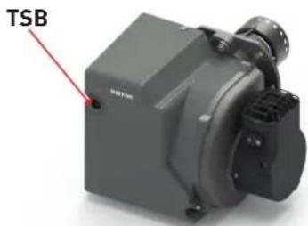
Fig. 29
5.4 Adjustment
The burners leave the factory calibrated as shown in the paragraph "Factory calibration", but during installation they normally require some adjustments to the settings described below, which must be carried out while the burner is operating. The adjustments must be made exclusively by the Sime Technical Service or by professionally qualified personnel.
To adjust the position of the air shutter, use the Allen key (1) provided and turn the screw (2):
- clockwise to increase the shutter's opening (Q increases, CO2 decreases;
- anti-clockwise to decrease the air shutter's opening (Q decreases, CO2 increases).
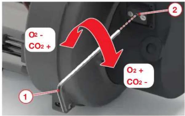
Fig. 30
5.5 Pump pressure adjustments
To adjust the pump pressure and thus the burner's power output:
- remove the screw (8) and connect a pressure gauge (if it has not been done previously);
- turn the screw (7) until reaching the desired pressure value, which appears on the pressure gauge 7-15 bar.
NB.
After modifying the fuel pressure value, we suggest leaving the burner running for a few minutes to stabilise the new conditions. Subsequently, measure the combustion parameters (CO, CO2 and the smoke index - The CO must not exceed 50ppm). If the values are as desired, stop the appliance and restore the initial conditions.
If not, repeat the procedure described.
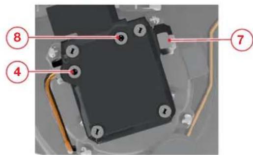
Fig. 31
5.6 Checking the pump's negative pressure
To make sure that the pump can work properly we suggest verifying the negative pressure value during suction. To do this, remove the screw (4) (if this has not been done previously) and install a vacuum gauge on which to read the negative pressure value.
The maximum allowed negative pressure is 0,4 bar.
NB.
With a negative pressure higher than 0,4 bar, diesel turns into gas, causing cavitation of the pump and resulting damages to the latter. Check the entire fuel intake line, including the filter on the line and the one (H) inside the pump.
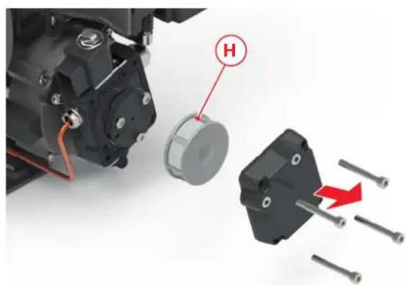
natural_image
Mechanical assembly diagram showing a motor component with a highlighted part labeled 'H' and a red arrow indicating motion (no text or symbols beyond labels)Fig. 32
5.7 Commissioning adjustments
Confirm the work carried out in the commissioning report shown below with a X or a √.
| Commissioning works Notes Done | ||
| Check that the heating system has filled up adequately and has deaerated | ||
| Verify the fume exhaust system | ||
| Check that there are no leakages throughout the hydraulic circuit | ||
| Start the burner and check that it works efficiently | ||
| Measure the combustion parameters and record the fundamental data of the initial start-up | ||
| Explain to the owner or to person in charge of the domestic system where the burner is installed the importance of ensuring regular conditions for the entry of combustion air and the expulsion of combustion by-products; in addition, they must also point out that no modification can be made on the thermal machine [consisting of the extraction system, heat generator and flue] that can alter the system's correct operation |
Conformation of the correct commissioning:
Stamp / date / signature of the company:
5.7.1 Setting and measured values
Customer:
Heating system:
| BOILER | ||
| Model | ||
| Power | kW | |
| kcal/h | ||
| BURNER | ||||
| Model | SIME FUEL 25 EV (vers. std) | SIME FUEL 35 EV (vers. std) | SIME FUEL 25 EV (vers. HE) | SIME FUEL 35 EV (vers. HE) |
| Serial number | ||||
| Power kW | ||||
| Nozzle dimensions gph | ||||
| Type of spray/nozzle | ||||
| Ventilation pressure mbar | ||||
| Combustion chamber pressure mbar | ||||
| Air shutter Notch | ||||
| Diesel flow rate kg/h | ||||
| Oil pressure (pump) bar | ||||
| CO_2 Vol. % | ||||
| CO mg / kWh | ||||
| ppm | ||||
| NOx mg / kWh | ||||
| ppm | ||||
| Room temperature °C | ||||
| Flue gas temperature (gross) °C | ||||
| Pressure at the flue mbar | ||||
| Boiler performance % | ||||
Date:
Signature:
6.1 Adjustments
Periodic maintenance is MANDATORY BY LAW and is important for the safety, efficient operation and long-lasting life of the burner, while it also helps to reduce consumption and polluting emissions.
We therefore recommend the user to entrust a professionally qualified technician to carry out maintenance on the appliance on an ANNUAL basis.

CAUTION
- The operations described below must ONLY be carried out the professionally qualified personnel who MUST wear suitable accident-prevention equipment.
- Make sure that the temperature of the components inside the device or of the system pipes are not too hot (risk of burns).
- Shift the main switches of the system and of the boiler to "OFF".
- Close the fuel shut-off valve.
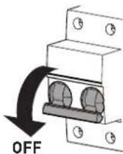
Fig. 33
6.2 Removing the burner
To remove the burner form the boiler, proceed as follows:
- loosen the nut (9) fastening the burner to the boiler;
- turn the burner (10) slightly to the right and extract it from the boiler;
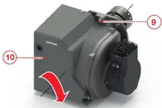
Fig. 34
- loosen the two screws (1) and slide off the cover (2);
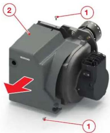
Fig. 35
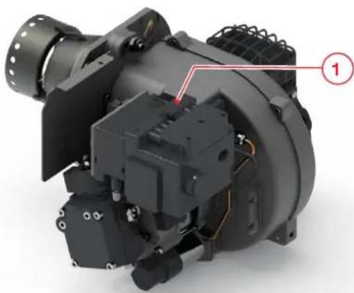
- detach the 7-pole plug (1) from the burner.
natural_image
3D mechanical assembly with black housing and wiring, no visible text or symbolsFig. 36
To facilitate maintenance operations, secure the burner to the boiler by inserting the fixing screw (9) through the hole (12) on the foot. Use one of the three square-shaped grooves on the foot to secure the burner rotated in the most suitable position for performing the required maintenance operation.
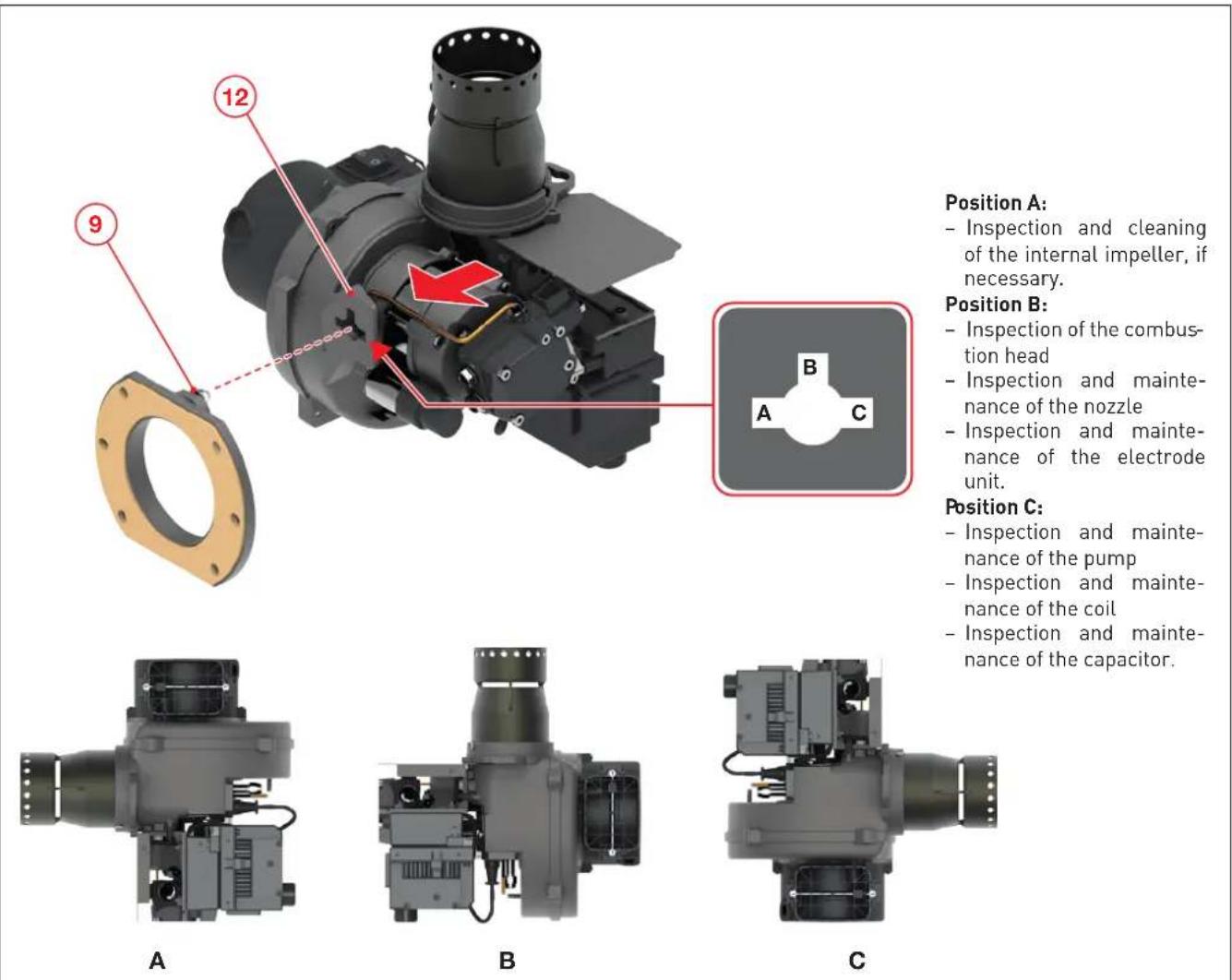
Position A:
- Inspection and cleaning of the internal impeller, if necessary.
Position B:
- Inspection of the combustion head
- Inspection and maintenance of the nozzle
- Inspection and maintenance of the electrode unit.
Position C:
- Inspection and maintenance of the pump
- Inspection and maintenance of the coil
- Inspection and maintenance of the capacitor.
Fig. 37
POSITION A
6.2.1 Cleaning the impeller
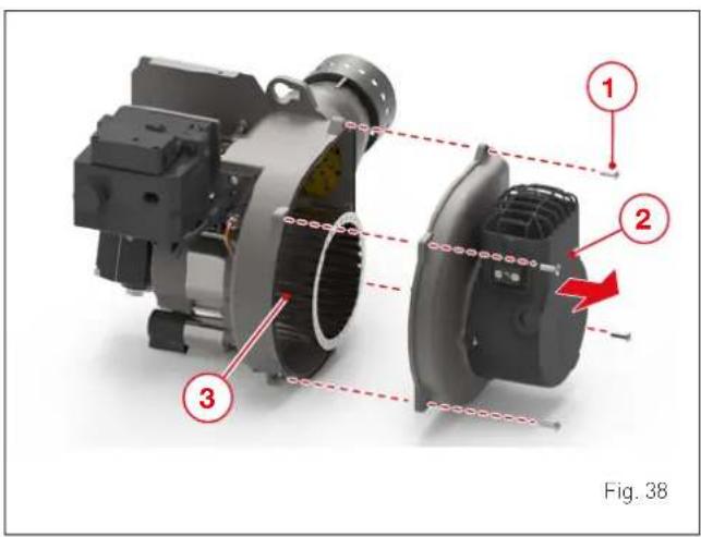
Check that there is no dust inside the impeller as this could reduce the combustion performance. Perform maintenance operations while being careful not to damage the fan. Check that the impeller is properly positioned inside the burner body.
Observe the following sequence:
- loosen the screws (1) and remove the air intake duct (2);
- clean the impeller (3) and the air duct using a paintbrush;
- if necessary, dismantle the impeller and mount it back on.
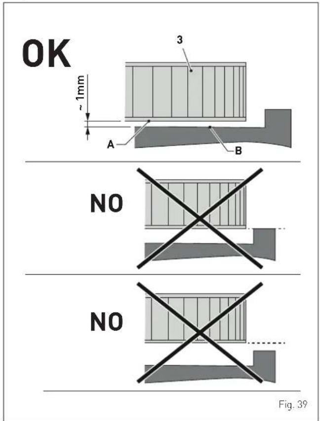
If the motor and/or impeller (3) must be replaced, make sure that the lower rotation surface (A) of the impeller is roughly 1 mm away from the surface (B) of the housing body, as illustrated in figure.
6.2.2 Replacing the coil
The pump coil is designed and manufactured to withstand temperatures up to 85°C.
In case of malfunctions or faults, replace the coil as explained below:
- remove the connector (1);
- remove the nut (2) using the spanner provided;
- extract the coil (3) and replace it;
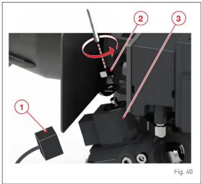
- mount the components back on by performing the above steps in reverse order.
- Check the fuel supply components (pipe, pump, fuel supply pipe) and their connections for leakages or signs of wear, and replace them if necessary;
- check that the electrical connections and the connecting cables are not damaged, and replace them if necessary;
- inspect the pump filter and clean it if necessary;
- inspect the fan and its housing, and check whether there are any damages;
- inspect and clean the combustion head;
- check the ignition electrodes and adjust them, or replace them if necessary;
- replace the nozzle;
- mount the combustion head. Observe the adjustment dimensions;
- mount the burner;
- start the burner, check the flue gas data and adjust the burner settings, if necessary;
- the fuel pipes must be inspected annually and replaced after 2 years;
- inspect and clean the components of the main burner.
POSITION B
6.2.3 Cleaning and replacing the combustion head
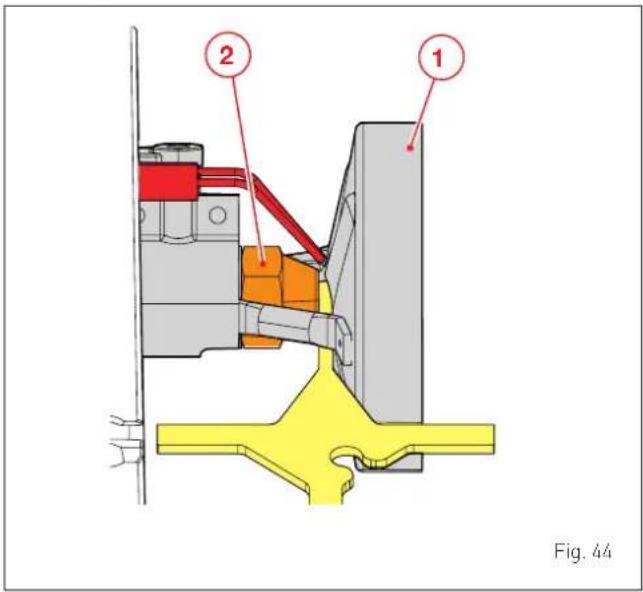
- Use a screwdriver to remove the screws (1) then pull out the nose (2);
- loosen the screw (3) with the Allen key provided and remove the diffuser (4) together with the electrode unit (5);
- to remove the nozzle (6) from the oil line, use a suitable tool of the right size;
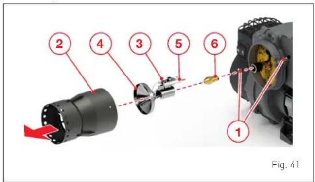
- make sure that all the components are in good condition, not damages by the high temperatures, clean and free of soot. Replace them if they are damaged;
- clean all the components properly;
- mount the components back on by performing the above steps in reverse order.

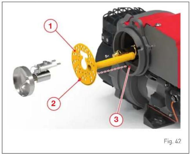
CAUTION
If the air distributor (1) must be removed from its housing, it must then be put back in place while making sure that the hole (2) is aligned with the pin (3).
6.2.4 Checking the position of the diffuser
To check the position of the diffuser:
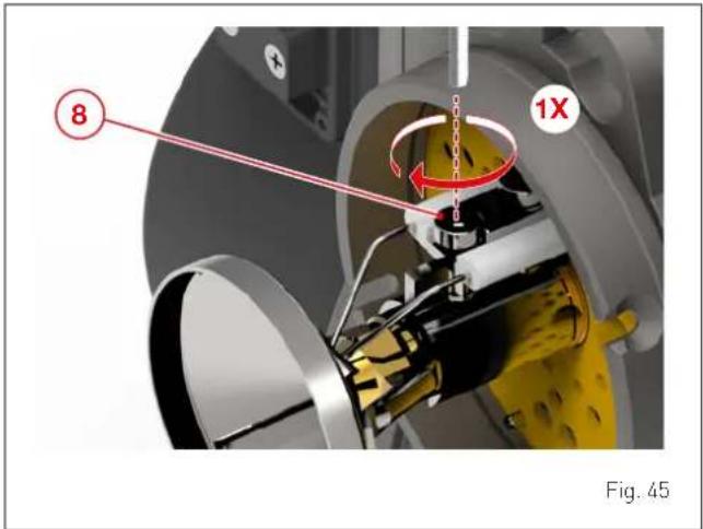
- remove the nose as described in the paragraph "Cleaning and replacing the combustion head";
- use the Allen key provided to loosen the screw (8) and adjust the diffuser. A single turn of the key is sufficient;
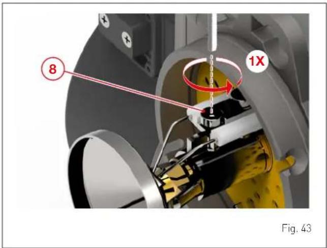
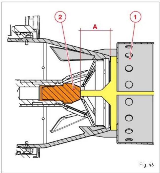
- check the distance between the diffuser (1) and the nozzle (2), as shown in the figure (use the template supplied with the burner);
- after adjusting the position of the diffuser, tighten the screw [8];
- mount the nose back on.
6.2.5 Checking he position of the combustion head
To check the position of the combustion head:
- check the distance between the combustion head (1) and the nozzle (2), as shown in the figure (use the template supplied with the burner).
6.2.6 Checking the position of the electrodes
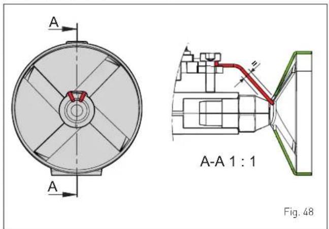
- check the gap between the electrode tips (2 mm) (use the template supplied with the burner);
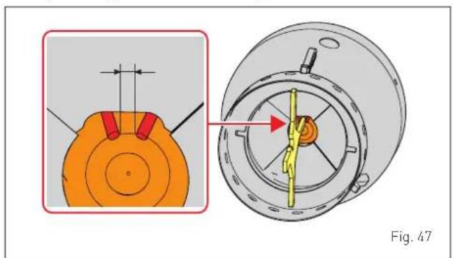
natural_image
Technical diagram of a mechanical component with cross-sectional view and close-up detail (no text or symbols)- check the position of the electrodes making sure that they are centred as shown in the figure.
POSITION C
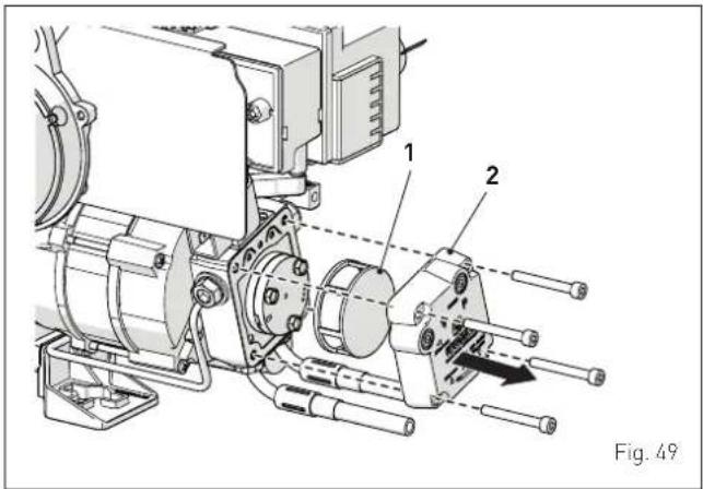
6.2.7 Cleaning the pump filter
To clean the filter (1), remove the cover (2) and extract the filter, After cleaning:
- mount the filter back on (1);
- check the seal of the cover (2) and replace it if necessary;
- put the cover (2) back on and tighten the screws firmly.
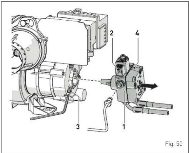
6.2.8 Checking the pump rotation
To verify whether the pump rotates freely:
- detach the oil pipe from its housing (1);
- detach the connector from the solenoid valve housing (2);
- loosen the screws (3) using the Allen key provided;
- remove the pump (4) and the connecting joint from the motor.
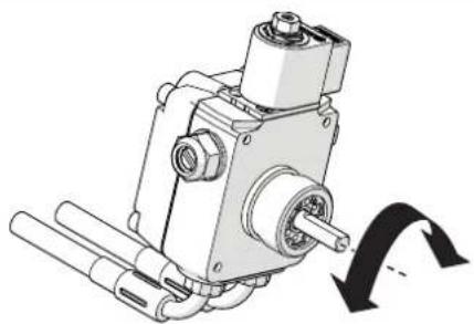
- manually turn the shaft (3 or 4 times clockwise and anti-clockwise).
natural_image
Mechanical assembly diagram showing a motor or gear mechanism with no visible text or symbolsFig. 51
Replace the pump if remains seized or if it resists manual rotation.
To mount the pump back on:
- apply the joint to the pump shaft (4) and insert it in the motor housing;
- screw the oil pipe onto the housing (1);
- put the connector back onto the solenoid valve housing (2).

WARNING
When the burner starts up, check that there are no leakages from the pump.
6.2.9 Scheduled replacement of worn components
The table below shows the components subject to wear and their life cycle, at the end of which they should be replaced exclusively by the SIME Technical Service or by professionally qualified personnel
| Components | Life cycle (years) |
| Nozzles 1 | |
| Seals 2 | |
| Fuel supply pipes 2 | |
| Flame monitoring systems 3 | |
| Ignition electrodes 2 | |
| Power cable 5 | |
| Magnesium anode 1 |
6.2.10 Replacing the capacitor
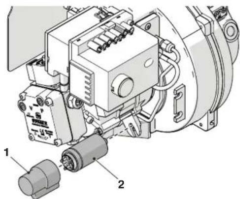
To replace the capacitor:
- remove the protective cap (1) from the capacitor (2);
natural_image
Technical diagram of an industrial machine with labeled components (no text or symbols present)Fig. 52
- disconnect the power supply to the capacitor;
- connect a tester to the Faston terminals of the capacitor; if the reading is roughly 10% higher than the rated capacity shown on the capacitor, it means that the capacitor is damaged.
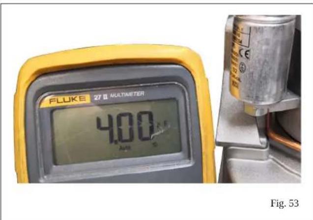
The value shown in the figure refers to a 4 F capacitor and is purely indicative. Please refer to the characteristics of the capacitor mounted on the burner.
- Remove the capacitor (2) and replace it
- Mount the components back on by performing the above steps in reverse order.

CAUTION
- After completing the maintenance operations and mounting the burner back onto the boiler, the burner must be started up by performing the procedure described in the chapter "COMMISSIONING".
7 POSSIBLE FAULTS AND SOLUTIONS
In case of a burner malfunction [red signal of the Unlock Button (TSB)], it is advisable to first check whether:
– There is any fuel in the tank
- The shut-off valves of the fuel are all open
- The safety device of the boiler is unlocked
Subsequently, verify in what phase of the programme the malfunction occurred and, after solving the problem, press the TSB button to restart the burner.

CAUTION
To prevent damages to the appliance or to the system, do not unlock the burner more than 2 times consecutively. If further lock-outs occur, promptly contact the Assistance Service Sime.

CAUTION
ONLY use original spare parts to replace the burner's components. Otherwise, the appliance's warranty may be voided.
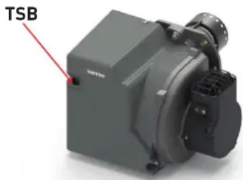
Fig. 54
7.1 Troubleshooting
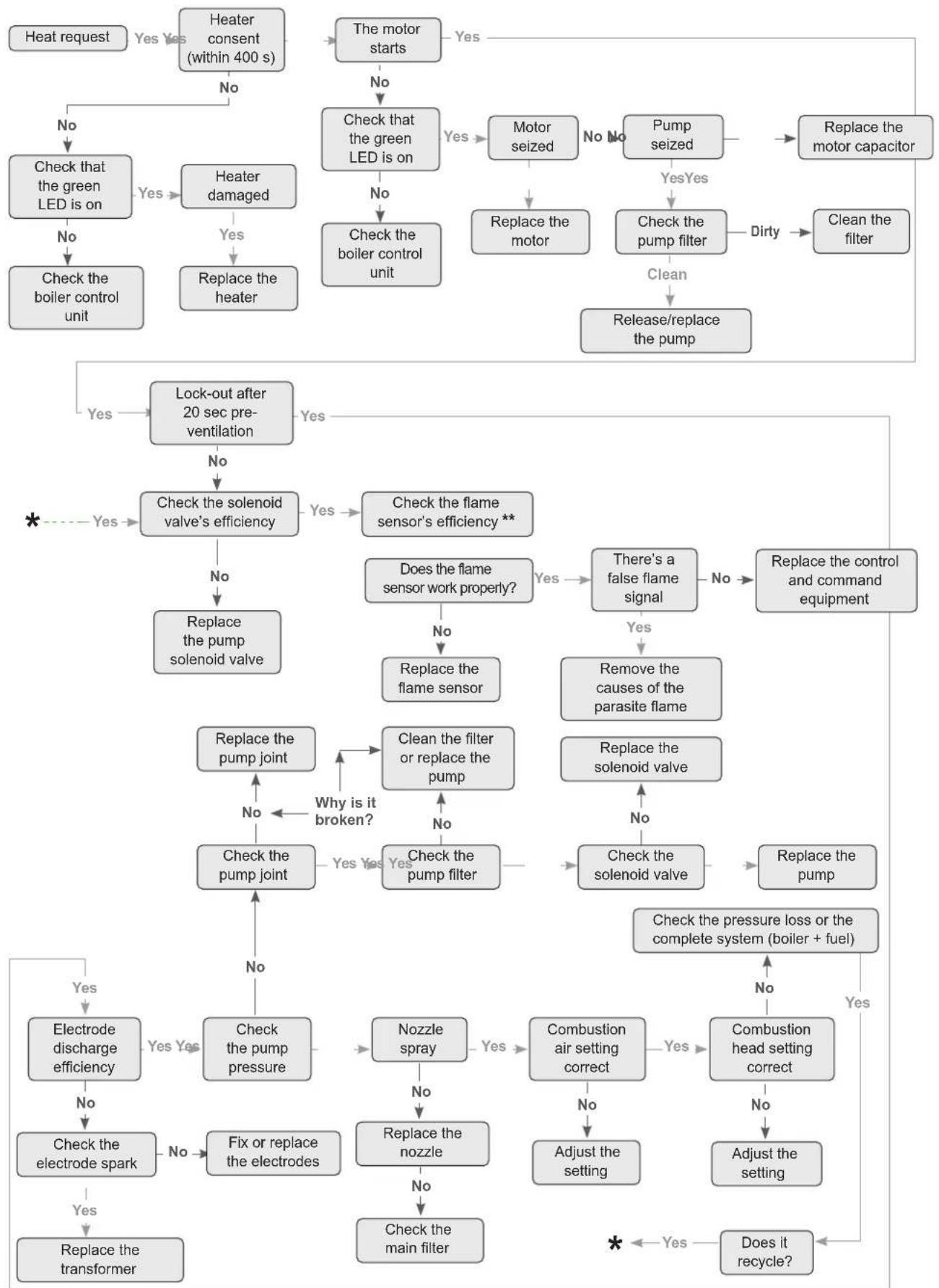
flowchart
graph TD
    A["Heat request"] --> B{Heater consent (within 400 s)}
    B -->|No| C["Check the green LED is on"]
    B -->|Yes| D["Heater damaged"]
    D --> E["Replace the boiler control unit"]
    C --> F{Check the boiler control unit}
    F -->|No| G["Lock-out after 20 sec pre-ventilation"]
    F -->|Yes| H["Check the boiler control unit"]
    G --> I{Check the solenoid valve's efficiency}
    I -->|No| J["Replace the pump solenoid valve"]
    I -->|Yes| K{Check the flame sensor's efficiency **}
    K -->|Yes| L["Does the flame sensor work properly?"]
    K -->|No| M["Replace the flame sensor"]
    L --> N{Check the pump joint}
    N -->|No| O["Check the pump joint"]
    N -->|Yes| P{Clean the filter or replace the pump}
    P -->|Yes| Q["Check the pump filter"]
    P -->|No| R{Check the pump joint}
    R -->|Yes| S["Check the pump pressure"]
    R -->|No| T{Check the pump joint}
    T -->|Yes| U["Electrode discharge efficiency"]
    T -->|No| V["Check the electrode spark"]
    T -->|No| W["Fix or replace the electrodes"]
    T --> X{Check the main filter}
    X --> Y["Combustion air setting correct"]
    Y -->|No| Z["Adjust the setting"]
    Y -->|Yes| AA{Combustion head setting correct}
    AA -->|No| AB["Adjust the setting"]
    AA -->|Yes| AC{Combustion head setting correct}
    AC -->|No| AD["Does it recycle?"]
    AC -->|Yes| AE{Combustion head setting correct}
    AE -->|No| AF["Adjust the setting"]
    AE -->|Yes| AG{Combustion head setting correct}
    AG -->|No| AH["Adjust the setting"]
    AG -->|Yes| AI{Combustion head setting correct}
    AI -->|No| AJ["Adjust the setting"]
    AI -->|Yes| AK{Combustion head setting correct}
    AK -->|No| AL["Adjust the setting"]
    AK -->|Yes| AM{Combustion head setting correct}
    AM -->|No| AN["Adjust the setting"]
    AM -->|Yes| AO{Combustion head setting correct}
    AO -->|No| AP["Adjust the setting"]
    AO -->|Yes| AQ{Combustion head setting correct}
    AQ -->|No| AR["Adjust the setting"]
    AQ -->|Yes| AS{Combustion head setting correct}
    AS -->|No| AT["Adjust the setting"]
    AS -->|Yes| AU{Combustion head setting correct}
    AU -->|No| AV["Adjust the setting"]
    AU -->|Yes| AW{Combustion head setting correct}
    AW -->|No| AX{Combustion head setting correct}
    AX -->|No| AY["Adjust the setting"]
    AX -->|Yes| AZ{Combustion head setting correct}
    AZ -->|No| BA{Combustion head setting correct}
    BA -->|No| BB{Combustion head setting correct}
    BB -->|No| BC{Combustion head setting correct}
    BC -->|No| BD{Combustion head setting correct}
    BD -->|No| BE{Combustion head setting correct}
    BE -->|Yes| BF{Combustion head setting correct}
    BF -->|No| BG{Combustion head setting correct}
    BG -->|No| BH{Combustion head setting correct}
    BH -->|No| BI{Combustion head setting correct}
    BI -->|Yes| BJ{Combustion head setting correct}
    BJ -->|No| BK{Combustion head setting correct}
    BK -->|No| BL{Combustion head setting correct}
    BL -->|Yes| BM{Combustion head setting correct}
    BM -->|No| BN{Combustion head setting correct}
    BN -->|Yes| BO{Combustion head setting correct}
    BO -->|No| BP{Combustion head setting correct}
    BP -->|Yes| BQ{Combustion head setting correct}
    BQ -->|No| BR{Combustion head setting correct}
    BR -->|Yes| BS{Combustion head setting correct}
    BS -->|No| BT{Combustion head setting correct}
    BT -->|Yes| BU{Combustion head setting correct}
    BU -->|No| BV{Combustion head setting correct}
    BV -->|Yes| BW{Combustion head setting correct}
    BW -->|No| BX{Combustion head setting correct}
    BX -->|Yes| BY{Combustion head setting correct}
    BY -->|No| BZ{Combustion head setting correct}
    BZ -->|Yes| CA{Combustion head setting correct}
    CA -->|No| CB{Combustion head setting correct}
    CB -->|Yes| CC{Combustion head setting correct}
    CC -->|No| CD{Combustion head setting correct}
    CD -->|Yes| DE{Combustion head setting correct}
    DE -->|No| BE
    DE -->|Yes| BE
Fig. 55
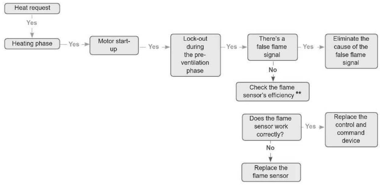
flowchart
graph TD
    A["Heat request"] -->|Yes| B["Heating phase"]
    B -->|Yes| C["Motor start-up"]
    C -->|Yes| D["Lock-out during the pre-ventilation phase"]
    D -->|Yes| E["There's a false flame signal"]
    E -->|No| F["Check the flame sensor's efficiency **"]
    F -->|Yes| G["Replace the control and command device"]
    F -->|No| H["Does the flame sensor work correctly?"]
    H --> I["Replace the flame sensor"]
Fig. 56
(**) CHECKING THE FLAME SENSOR'S EFFICIENCY
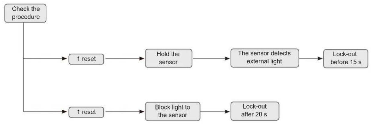
flowchart
graph TD
    A["Check the procedure"] --> B["1 reset"]
    B --> C["Hold the sensor"]
    C --> D["The sensor detects external light"]
    D --> E["Lock-out before 15 s"]
    A --> F["1 reset"]
    F --> G["Block light to the sensor"]
    G --> H["Lock-out after 20 s"]
Fig. 57
8.1 Use of biodiesel
The burner is suitable for working with a biodiesel blend of up to 10%. This is a minimum requirement in conformity to the applicable standards, the regional regulations and FAME requirements in conformity to EN 14214.

CAUTION
If the burner must be used with fuels containing biofuel percentages above 10%, contact the manufacturer.
8.2 Important suggestions for using biofuel blends
8.2.1 Introduction
The growing attention towards renewable and sustainable energy foreshadows an increasingly widespread use of biofuels. If you plan to use them, a few technical aspects must be taken into account for reducing potential faults in the burner and in the system, besides the risk of fuel leakages.
"Liquid biofuel" is a broad term that identifies oil deriving from numerous raw materials, including recycled cooking oil. These types of oil must be considered and treated differently to common mineral and fossil fuels, since they are more acidic, hygroscopic and less stable.
Special care must be taken when storing the fuel, in the conveying piping, in the ancillary equipment, during filtration and in the choice of the burner.
The classification of biofuel is important for the efficient operation of the equipment.

CAUTION
The owner or the manager of the plant is responsible for thoroughly analysing the potential risks associated with the introduction of a biofuel blend, the suitability of the appliances and the installation.
8.2.2 General information and instructions
The fuel supplier must demonstrate conformity to an accredited quality management system for its own storage, mixing and delivery processes.
In the installations, make sure that all the materials and sealing devices of the storage tank and of the pipe conveying the oil to the burner are compatible with biofuels.
The tank must include a high-quality biocompatible oil filter plus a size 60 micron secondary filter for protecting the burner against contaminations.
Whenever an existing tank must be used to store the oil, in addition to the above-mentioned checks on the materials, it is essential that the tank be inspected above all to verify its conditions and to make sure that it does not contain water or other contaminants. If contaminants are found, deep cleaning must be performed. If this is not done, the hygroscopic nature of the fuel could cause complex components to dissolve and to detach causing the appliance to malfunction.
Depending on the storage tank's capacity and on how the plant is used, fuels can remain inside it for a considerable period of time. Consult the biofuel distributor for information on how to use biocides to prevent microbial growth inside the tank and for instructions on fuel filtering.
When commissioning the burner, check that all the combustion parameters conform to the recommended values appearing in the appliance's technical manual.
Check the filters of the pipe and of the burner's oil pump and replace them if necessary:
- At least every 4 months during burner use
- Prior to starting the burner following a prolonged shutdown
- More frequently in case of contamination.

WARNING
Be particularly careful during checks and inspections for detecting fuel leakages from sealing devices, seals and flexible pipes.

WARNING
If a biofuel blend is used, consult the biofuel distributor.
natural_image
3D rendering of a gray industrial machine component with mounting bracket and control panel (no visible text or symbols)natural_image
Technical diagram showing a mechanical component with cross-sectional view and dimension lines (no text or symbols)Fig. 10
natural_image
Technical diagram of a circular mechanical component with radial slots and central hub, labeled 'A' at both ends (no text or symbols beyond labels)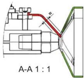
Fig. 11
Fig. 13
Fig. 14
natural_image
Close-up of a black industrial motor or fan assembly with red arrow indicating rotation (no text or symbols visible)Fig. 15
Fig. 17
4.8 Circuito aceite
1 Electroválvula
natural_image
Mechanical assembly diagram showing a component with red arrows indicating direction, no visible text or symbolsFig. 22
| H (m) | Lunghezza tubo (m) | ||
| ∅6 mm ∅8 mm ∅10 mm | |||
| 0,5 19 60 | 100 | ||
| 1 21 66 | 100 | ||
| 1,5 23 72 | 100 | ||
| 2 25 79 | 100 | ||
| 2,5 27 85 | 100 | ||
| 3 29 91 | 100 | ||
| 3,5 31 98 | 100 | ||
| ---- | |||

ATENCIÓN
- X < 20m
natural_image
3D mechanical assembly diagram showing internal components with no visible text or symbols
ADVERTENCIA
Es obligatorio:
Fig. 30
natural_image
Mechanical assembly diagram showing a motor component with a highlighted part labeled 'H' and a red arrow indicating motion (no text or symbols beyond label)Fig. 32
natural_image
3D mechanical assembly of a motor or generator unit with no visible text or symbolsFig. 36
natural_image
Technical diagram showing a mechanical component with cross-sectional view and dimension lines (no text or symbols)natural_image
Mechanical component diagram showing a rotating shaft and housing assembly (no text or symbols)natural_image
Technical diagram of an industrial electrical component with labeled parts (1 and 2), no readable text or symbols beyond labelsFig. 52
- Circuito olio
- Sistema monotubo (optional)
- ATTENZIONE
- AVVERTENZA
- É obbligatorio:
- SAFETY WARNINGS AND REGULATIONS
- WARNINGS
- RESTRICTIONS
- IT IS FORBIDDEN
- COMPLIANCE
- SYMBOLS
- WARNING
- ELECTRICAL HAZARD
- CAUTION
- DANGER: FLAMMABLE MATERIAL
- WARNING: HOT SURFACE
- SPECIFIC WARRANTY
- DISPOSAL OF THE EQUIPMENT
- TABLE OF CONTENTS
- SAFETY 38
- GENERAL 39
- SPECIFICATIONS 43
- INSTALLATION 45
- COMMISSIONING 51
- MAINTENANCE 56
- POSSIBLE FAULTS AND SOLUTIONS 62
- APPENDIX 65
- General information
- Intended use
- Primary dangers
- LOSS OF FUEL
- GENERAL
- Description of the burner
- Supply
- Identification
- Structure
- Burner structure
- Combustion head structure
- Operating logic (two-pipe system)
- Electrical control and command equipment
- Operating function
- Controlled stoppage
- Safety function
- SPECIFICATIONS
- Wiring diagram
- INSTALLATION
- Receiving the product
- Dimension and weights
- Installation room
- Fume exhaust system
- Assembly/adjustment tools
- Preliminary checks prior to mounting the burner
- Mounting the burner
- Removing and mounting the cover
- Oil circuit
- Hydraulic diagram of the fuel pump
- Fuel pump
- Two-pipe system (standard)
- Single-pipe system (optional)
- Two-pipe systems
- Electrical connections to the boiler
- Removing the burner
- NB.
- COMMISSIONING
- Preliminary operations
- Then verify that:
- Factory calibration
- Reference conditions
- Initial start-up of the burner
- Adjustment
- Pump pressure adjustments
- Checking the pump's negative pressure
- Commissioning adjustments
- Setting and measured values
- Adjustments
- Removing the burner
- Position A:
- Position B:
- Position C:
- POSITION A
- Cleaning the impeller
- Replacing the coil
- POSITION B
- Cleaning and replacing the combustion head
- Checking the position of the diffuser
- Checking he position of the combustion head
- Checking the position of the electrodes
- POSITION C
- Cleaning the pump filter
- Checking the pump rotation
- Scheduled replacement of worn components
- Replacing the capacitor
- POSSIBLE FAULTS AND SOLUTIONS
- Troubleshooting
- Use of biodiesel
- Important suggestions for using biofuel blends
- Introduction
- General information and instructions
- Circuito aceite
- ATENCIÓN
- ADVERTENCIA
- Es obligatorio:
Brand : SIME
Model : FUEL EV
Category : Boiler