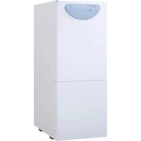
Aqua INOX - Boiler SIME - Free user manual and instructions
Find the device manual for free Aqua INOX SIME in PDF.


| Product type | Oil boiler |
| Brand | SIME |
| Model | Aqua INOX |
| Use | Central heating and domestic hot water production |
| Fuel | Oil (heating oil) |
| Useful output | 31.3 kW (AQUA 30 INOX) / 40.0 kW (AQUA 40 INOX) |
| Heat input | 34.8 kW (AQUA 30 INOX) / 44.3 kW (AQUA 40 INOX) |
| Dimensions (H x W x D) | 1690 x 460 x 830 mm (approx.) |
| Weight | 233 kg (AQUA 30 INOX) / 260 kg (AQUA 40 INOX) |
| Electrical supply | 230 V - 50 Hz, single-phase |
| Max. heating operating pressure | 4 bar |
| Max. cylinder operating pressure | 7 bar |
| Max. operating temperature | 95 °C |
| Heating adjustment range | 45 – 85 °C |
| DHW adjustment range | 30 – 60 °C |
| Domestic hot water tank capacity | 100 litres |
| Tank material | Stainless steel AISI 316L |
| Specific DHW flow rate (EN 625) | 21.6 l/min |
| DHW recovery time (25→55 °C) | 12 min |
| Heating expansion vessel | 10 l (AQUA 30 INOX) / 12 l (AQUA 40 INOX) |
| DHW expansion vessel | 4 l |
| Burner | Integrated oil burner, pre-calibrated |
| Protection anode | Magnesium, to be checked periodically |
| Recommended annual maintenance | Cleaning of flue passages, combustion head and nozzle replacement |
Frequently Asked Questions - Aqua INOX SIME
User questions about Aqua INOX SIME
0 question about this device. Answer the ones you know or ask your own.
Ask a new question about this device
Download the instructions for your Boiler in PDF format for free! Find your manual Aqua INOX - SIME and take your electronic device back in hand. On this page are published all the documents necessary for the use of your device. Aqua INOX by SIME.
USER MANUAL Aqua INOX SIME
Aqua INOX
CERTIFICAZIONE
DEL SISTEMA DI
QUALITA' AZIENDALE

ISO 9001
2000 VERSION
sime
ISTRUZIONI PER L'INSTALLATORE
INDICE
G 3/4" (UNI-HSO 228/1)
U Uscita sanitario
G 3/4" (UNI-ISO 228/1)
C Ricircolo
G 3/4" (UNI-ISO 228/1)
Fig. 1
1.3 DATI TECNICI
natural_image
Technical diagram of a mechanical assembly with a central rotating component and an upward arrow, labeled Fig. 11 (no text or symbols on the diagram itself)natural_image
Technical line drawing of a mechanical component with bolts and a central shaft (no text or symbols)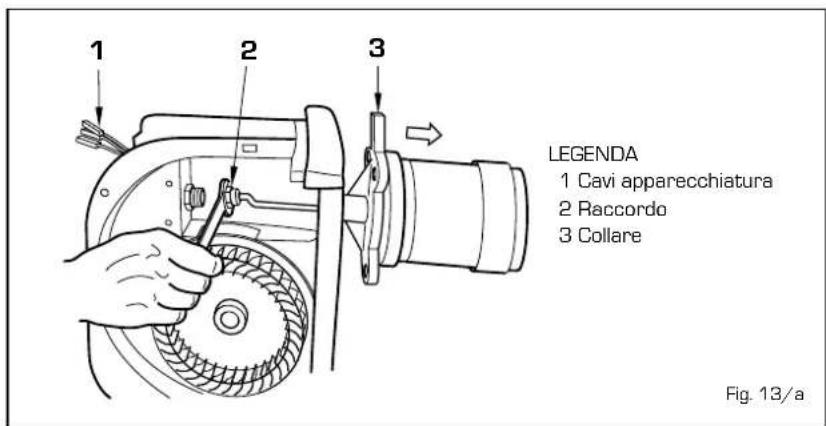
natural_image
Technical line drawing of an internal combustion engine assembly with a hand operating the valve (no text or labels present)AQUA 30 INOX
natural_image
Technical line drawing of a symmetrical mechanical or architectural component with no visible text or symbolsAQUA 40 INOX
natural_image
Technical line drawing of a mechanical component with symmetrical features and mounting brackets (no text or symbols)Fig. 14
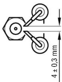
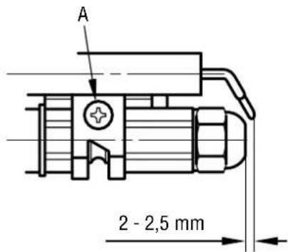
Fig. 15
4.6 PULIZIA E MANUTENZIONE CALDAIA
natural_image
Line drawing of two hands holding wrenches, no text or symbols presentnatural_image
Illustration of a hand holding a circular device with control panel and indicator lights (no text or symbols)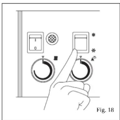
TERMOSTATO SICUREZZA
Fig. 21
SPEGNIMENTO CALDAIA
LEYENDA
LEYENDA
natural_image
Technical diagram of a mechanical assembly with a rotating component and an upward arrow, labeled Fig. 11 (no text or symbols on the diagram itself)natural_image
Technical line drawing of a mechanical component with mounting bracket and housing (no text or symbols)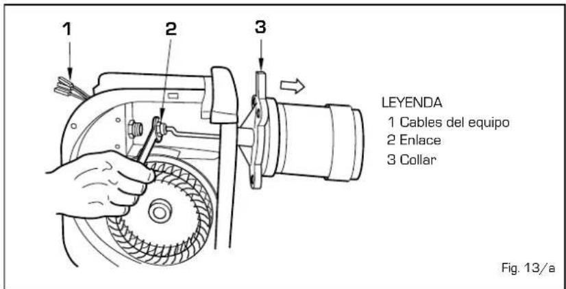
natural_image
Illustration of two hands using a wrench to adjust a mechanical component (no text or symbols present)natural_image
Hand holding a circular dial indicator with control buttons and symbols (no text or labels)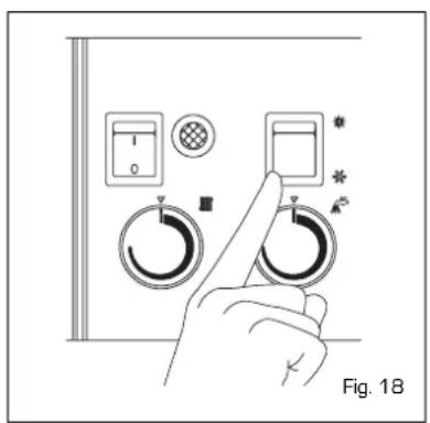
TERMOSTATO DE SEGURIDAD
C Ricirculo G 3/4" (UNI-HSO 228/1)
Fig. 1
1.3 DADOS TECNICOS
LEGENDA
natural_image
Technical diagram of a mechanical assembly with a circular component and an upward arrow, labeled Fig. 11 (no text or symbols on the diagram itself)natural_image
Technical line drawing of a mechanical component with no visible text or symbols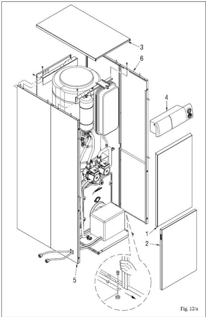
LEGENDA
natural_image
Line drawing of two hands using wrenches to adjust a mechanical component (no text or symbols)natural_image
Hand holding a circular dial with control panel and indicator lights (no text or symbols on the dial itself)
TERMOSTATO DE SEGURANÇA
Fig. 21
When carrying out commissioning of the boiler, you are highly recommended to perform the following checks:
- Make sure that there are no liquids or inflammable materials in the immediate vicinity of the boiler.
- Make sure that the electrical connections have been made correctly and that the earth wire is connected to a good earthing system.
- Check that the flue pipe for the outlet of the products of the combustion is unobstructed.
- Make sure that any shutoff valves are open.
- Make sure that the system is charged with water and is thoroughly vented.
- Check that the circulator is not blocked.
1 DESCRIPTION OF THE BOILER
1.1 INTRODUCTION
One of the features of the cast iron thermal group AQUA INOX with the integrated gas-oil burner is its functional silence and it has been designed in accordance with the european directives CEE 92/42.
The perfectly balanced combustion and the high yield allows it to economise considerably the operating costs.
Hot tap water is produced by a stainless steel hot water tank offering
exceptional dependability and durability.
The instructions given in this manual are provided to ensure proper installation and perfect operation of the appliance and should be strictly followed.
1.2 DIMENSIONS
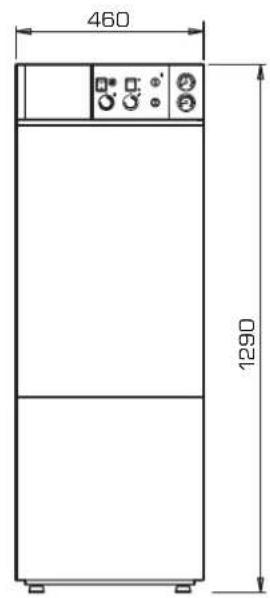
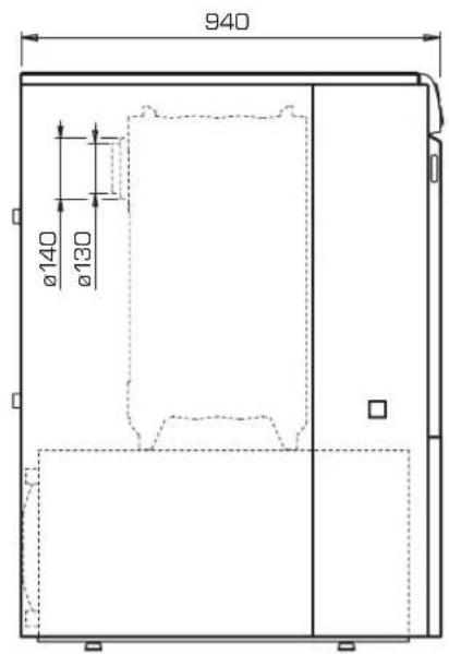
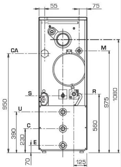
M C.H. flow R 1" (UNHISO 7/1)
R C.H. return Rp 1 1/4" (UNI-ISO 7/1)
E D.C.W. inlet G 3/4" (UNI-ISO 228/1)
U D.H.W. outlet G 3/4" (UNI-ISO 228/1)
C Recirculation G 3/4" (UNI-ISO 228/1)
Fig. 1
1.3 TECHNICAL FEATURES
| AQUA 30 AQUA 40 | |||
| Heat output * kW 31.3 (27.5) 40.0 (35.2) | |||
| kcal/h 26,900 (23,700) 34,400 (30,300) | |||
| Heat input * kW 34.8 (30.6) 44.3 (39.0) | |||
| kcal/h 29,900 (26,300) 38,100 (33,500) | |||
| Type | B23 | B23 | |
| Elements | n° | 4 | 5 |
| Maximum water head | bar | 4 | 4 |
| Water content | l | 31 | 35 |
| Expansion vessel | |||
| Water content | l | 10 | 12 |
| Preloading pressure | bar | 1 | 1 |
| Loss of head smoke | mbar | 0.16 | 0.21 |
| Combustion chamber pressure | mbar | -0.02 | -0.02 |
| Suggested chimney depression | mbar | 0.18 | 0.24 |
| Smoke temperature * | °C | 176 (166) | 200 (186) |
| Smoke flow * | m3n/h | 42 (38.4) | 53.5 (48.9) |
| CO2* | % | 13 (12.5) | 13 (12.5) |
| Maximum temperature | °C | 95 | 95 |
| Power consumption | W | 225 | 185 |
| Adjustment range heating | °C | 45÷85 | 45÷85 |
| Adjustment range D.H.W. | °C | 30÷60 | 30÷60 |
| D.H.W. production | |||
| Tank capacity | l | 100 | 100 |
| D.H.W. flow rate EN 625 | l/min | 21.6 | 21.6 |
| Contin. D.H.W. flow rate Δt 30°C * | l/h | 830 (790) | 830 |
| Recuper. time between 25°C and 55°C | min | 12 | 12 |
| D.H.W. expansion vessel | l | 4 | 4 |
| D.H.W. tank maximum water head | bar | 7 | 7 |
| Gas-oil burner | |||
| Burner nozzle * | 0.75 60°W (0.65 60°W) | 0.85 60°W | |
| Pump pressure * | bar | 12.5 (13) | 14 (11) |
| Shutter regulator position * | 5.2 (4.1) | 6.1 (5.5) | |
| Weight | kg | 233 | 260 |
| * The date shown between the brackets refer to the factory settings. | |||
1.4 MAIN COMPONENTS
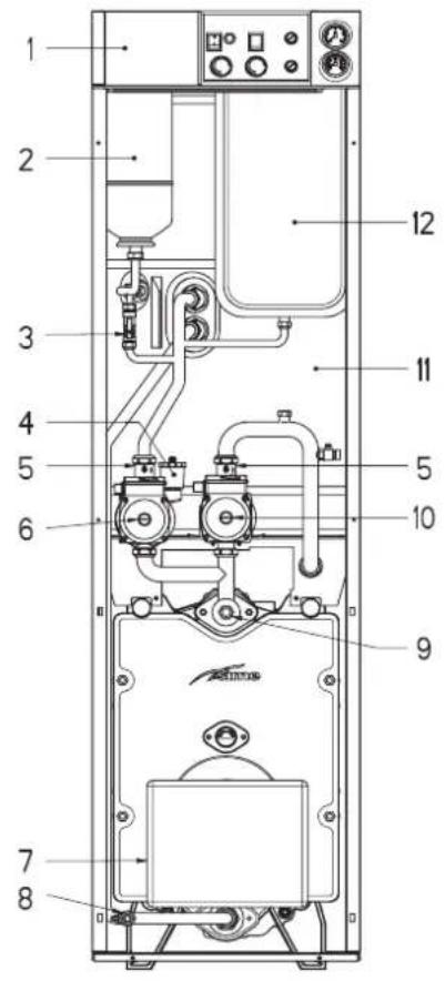
KEY
1 Control panel
2 D.H.W. expansion vessel
3 Filling
4 Air vent valve
5 Control valve
6 Tank pump
7 Gas-oil burner
8 Boiler drain
9 Bulb housing sheath
10 System pump
11 100 litre tank
12 Expansion vessel
Fig. 2
1.5 FUNCTIONAL DIAGRAM
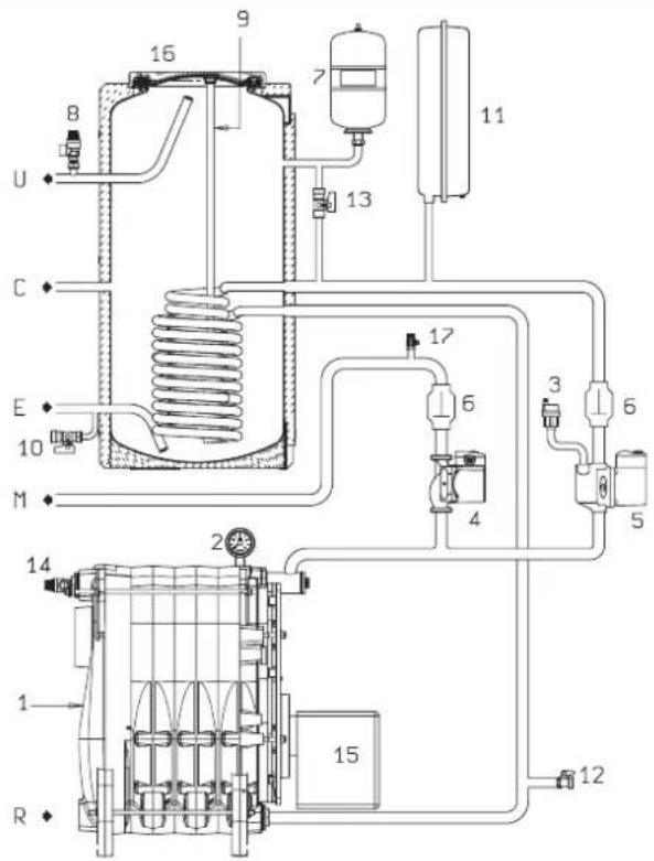
KEY
1 Boiler body
2 Hydrometer
3 Air relief valve
4 System pump
5 Tank pump
6 Control valve
7 Tank expansion vessel
8 Tank safety valve
9 Magnesium anode
10 Tank drainer cock
11 Expansion vessel
12 Boiler drainer cock
13 Filling
14 Safety valve
15 Gas-oil burner
16 100 litre tank
17 Air vent valve
Fig. 3
2 INSTALLATION
2.1 BOILER ROOM
The boilers with a rating of more than 35 kW must be equipped with a technical room whose dimensions and requirements correspond to the current standards and regulations.
The minimum distance between the walls of the room and the boiler must not be less than 0.60 m., while the minimum height between the top of the boiler and the ceiling must be at least 1 m. which can be reduced to 0.50 m. for boilers with incorporated heaters (however the minimum height of the boiler room must not be less than 2.5 m).
The boilers with a rating of less than 35 kW can be installed only in perfectly air-vented rooms.
To circulate air in the room, air vents must be made on the outside walls which satisfy the following requirements:
- Have a total surface area of at least 6 cm ^2 for each installed Kw of thermal capacity and however not less than 100 cm ^2 .
- To be situated as close as possible to the floor, unobstructable and protected by a grate which does not reduce the air passage area.
2.2 CONNECTING UP SYSTEM
Before proceeding to connect up the boiler, you are recommended to make the water circulate in the piping in order to eliminate any foreign bodies that might be detrimental to the operating efficiency of the appliance.
For connecting up the pipes, make sure to follow the indications illustrated in fig. 1. The connections should be easy to disconnect using pipe unions with orientable connections.
The shutoff valve must be connected to a suitable flow system and return pipes
2.2.1 System filling (fig. 4)
The boiler and the relative system must be filled operating on the bearing tap and the pressure of cold charging the system must be included between
1 - 1.2 bar. During filling the main switch should be left open.
Filling must be done slowly so as to allow any air bubbles to be bled off through the provided air vents. This operation can be made easy by positioning horizontally the block screw of
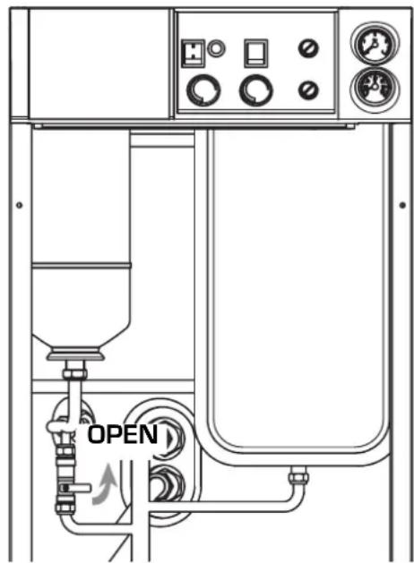
Fig. 4
the shutoff valve.
Upon completing the filling, put the screw back to its original position.
At the end of the operation make sure that the tap is closed.
In order that the boiler be capable of supplying treated water in the "AQUA INOX" version, all the air in the boiler's serpentine must be bled off at the first ignition.
This operation is made easy by positioning horizontally the block screw of the shutoff valve (5 fig. 2). After all the air has been bled off, put the screw back to its original position.
2.2.3 Characteristics of feedwater
IT IS ABSOLUTELY ESSENTIAL THAT THE WATER USED FOR THE CENTRAL HEATING SYSTEM SHOULD BE TREATED IN THE FOLLOWING CASES:
- Very extensive systems (with high contents of feedwater).
- Frequent addition of makeup water into the system.
- In case it is necessary to empty the system either partially or totally.
2.3 CONNECTING UP FLUE
The flue is of fundamental importance for the proper operation of the boiler; if not installed in compliance with the standards, starting the boiler will be difficult and there will be a consequent formation of soot, condensation and encrustation.
A flue therefore must satisfy the following requirements:
- be constructed with waterproof materials and resistant to smoke temperature and condensate;
- be of adequate mechanical resilience and of low heat conductivity;
- be perfectly sealed to prevent cooling of the flue itself:
- be as vertical as possible; the terminal section of the flue must be fitted with a static exhaust device that ensures constant and efficient extraction of products generated by combustion;
- to prevent the wind from creating pressure zones around the chimney top greater than the uplift force of combustion gases, the exhaust outlet should be at least 0.4 m higher than structures adjacent to the stack (including the roof top) within 8 m;
- have a diameter that is not inferior to that of the boiler union: square or rectangular-section flues should have an internal section 10% greater than that of the boiler union;
- the useful section of the flue must conform to the following formula:
$$ S = K \frac {P}{\sqrt {H}} $$
S resulting section in cm 2
K reduction coefficient for liquid fuels: 0.024
P boiler input in Kcal/h
H height of the flue in meters measured from the flame axis to the flue outlet into the atmosphere When dimensioning the flue, the effective height of the flue in meters must be considered, measured from the flame axis to the top of the flue, reduced by:
- 0.50 m for each change of direction of the connection union between boiler and flue;
- 1.00 for each horizontal metre of the union itself.
Our boilers are the B 23 type and do not need any particular connections other than the one to the flue as described above.
2.4 FUEL ADDUCTION
The fuel can be fed into the thermal group sideways, the ducts must be passed through the aperture on the right or left hand side of the shell for connection to the pump (fig. 5 - 5/a).
Important
- Make sure, before turning on the boiler, that the return tube is free. An excessive counter-pressure would break the pump seal.
- Make sure that the tubes are sealed.
- The maximum depression of 0.4 bar (300 mmHg) [see Table 1] must not be exceeded. Gas is freed from the fuel above that value and can cause cavitation of the pump.
- It's advisable to bring the return tube in the depression systems up to the same height of the intake tube. In this case the foot valve is unnecessary.
If instead the return tube arrives above the fuel level, the foot valve is indispensable.
Starting the pump
Turn on the burner to start the pump and check the flame ignition.
If a "lock out" occurs before fuel arrival, wait for at least 20 seconds then press the burner release button "RESET" and wait for the whole startup operation to repeat until the flame
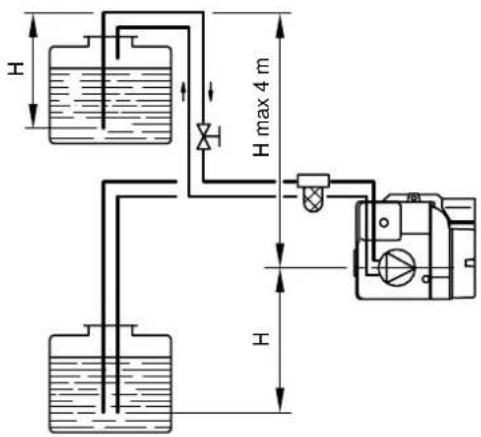
TABLE 1
| H meters | L (meters) | |
| øi tube 8 mm | øi tube 10 mm | |
| 0 | 35 | 100 |
| 0,5 | 30 | 100 |
| 1 | 25 | 100 |
| 1,5 | 20 | 90 |
| 2 | 15 | |
| 3 | 8 | |
| 3,5 | 6 | 20 |
H = Difference in level
L = Maximum length of the intake tube
Fig. 5
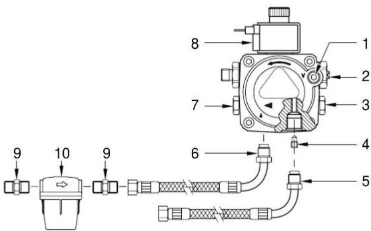
CONNECTIONS
1 Vacuometer attachment
2 Pressure regulator
3 Manometer attachment
4 By-pass screw
5 Back-flow flexible pipe (included in supply)
6 Suction flexible pipe (included in supply)
7 Auxiliary pressure intake
8 Valve
9 Racor 3/8" (included in supply)
10 Fuel feed line filter [included in supply]
ATTENTION:
- loosen the pump joints [5-6] before pointing the flexible pipes for bringing them out from the prefixed opening on the right/left hand side of the shell. Afterwards tighten the joints to the pump.
- The pump is prearranged for the double-tube function. Remove the by-pass screw [4] for single tube function.
Fig. 5/a
lights up.
2.5 BURNER ADJUSTMENTS
Each unit is shipped with a burner unit
equipped with a nozzle and calibrated at the factory; it is recommended, however, that the settings listed under point 1.3 be checked, with reference to atmospheric pressure at sea level. If it is necessary to adjust the burner
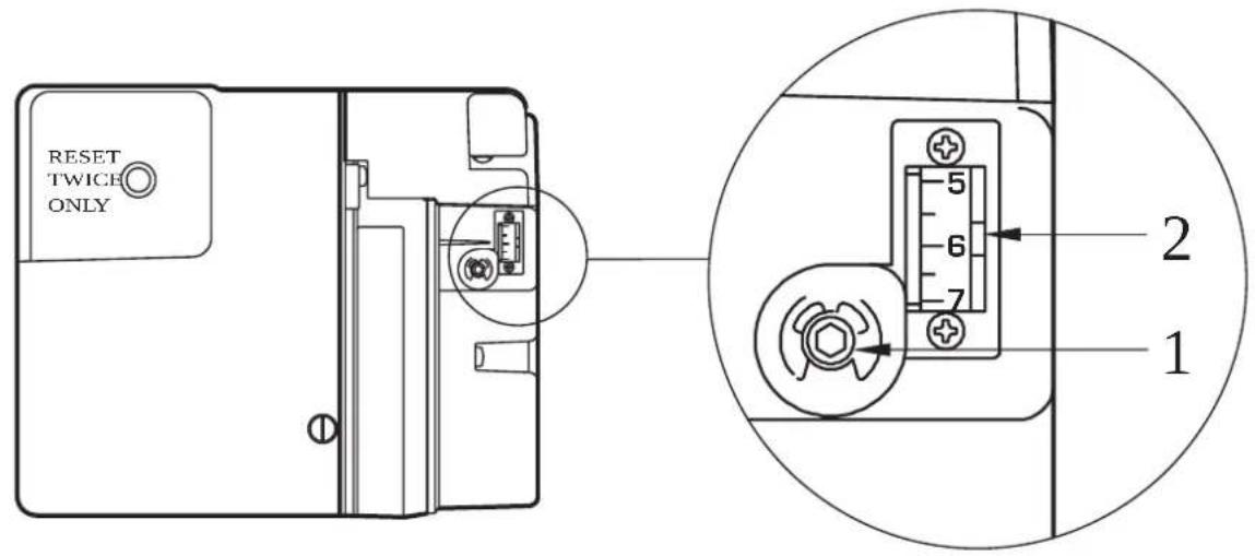
Fig. 6
differently from the factory settings, this should be done by authorised personnel following the instructions provided below. Remove the shell door to access the burner unit's controls.
2.5.1 Air lock adjustment
To adjust the air lock, loosen the screw (1 fig. 6) and slide the graduated scale (2 fig. 6) indicating the position air lock position. The values for adjustment of each unit are given in point 1.3.
2.5.2 Pump pressure adjustment
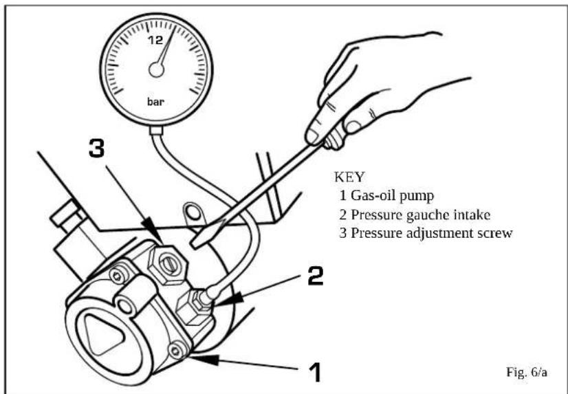
To adjust gas-oil pressure, turn the screw (3 fig. 6/a) and check pressure with a pressure gauche connected to the intake (2 fig. 6/a), making sure pressure corresponds to the value given under point 1.3.
2.6 HEATER UNIT
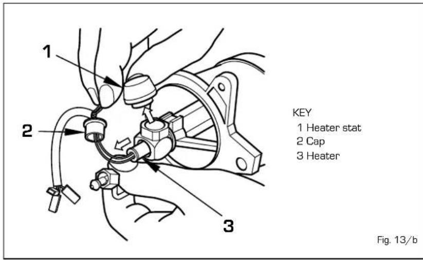
In "AQUA 30 INOX" models, the heater unit comes on with the consensus of the burner, after a delay of a maximum of 90 seconds required to bring fuel in the nozzle holder area up to a temperature of 65^ . Once this temperature has been reached, the thermostat, which is located above the preheater (1 fig. 13/b), will give consensus for the burner to start. The heater will remain on for as long as the burner stays on and go off when the burne goes off.
"AQUA 40 INOX" model have no heater unit, as it is not required.
2.7 ELECTRICAL CONNECTION
The boiler is supplied with an electric cable and the electric power supply to the boiler must be 230V-50Hz single-phase through a fused main switch.
The stat cable, whose installation is compulsory for obtaining a better adjustment of the room temperature, must be connected as shown in fig. 7.
NOTE: Device must be connected to an efficient earthing system.
SIME declines all responsibility for injury or damage to persons resulting from the failure to provide for proper earthing of the appliance.
Always turn off the power supply before doing any work on the electrical panel.
2.7.1 Wiring diagram
![1 2 3 4 5 6 7 8 9 10 11 12 13 14 15 16 17 18 19 20 21 22 23 24 25 26 27 28 29 TL IG N L 230V-50Hz 190W E/I TB OP 2 3 5 PB TS marcode nero SB BU TC TA PI A F VG M TR R KEY TS Safety stat SB Burner "lock out" warning light E/I Summer/Winter switch TA Room stat TC Boiler stat TL Limit stat IG Main switch PI C.H. pump OP Timer programmer TB Tank stat PB Tank pump RE Relay F Photoresistance VG Gas-oil valve M Motor A Burner control box R Heater [not in mod. "40"] TR Heater stat [not in mod. "40"] Fig. 7/b](/content/2026/04/713111/images/0bd1530e3ccd25dac5e71f96706f326d9e97e0b3bfc71ab34d5edde795c070f8.jpg)
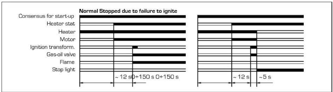
2.7.2 "AQUA 30 INOX" functional diagram
bar
| Category | Time Interval | | -------------------- | ------------- | | Consensus for start-up | ~12 s0÷150 s 0÷150 s | | Heater stat | ~12 s0÷150 s 0÷150 s | | Heater | ~12 s0÷150 s 0÷150 s | | Motor | ~12 s0÷150 s 0÷150 s | | Ignition transform. | ~12 s0÷150 s 0÷150 s | | Gas-oil valve | ~12 s0÷150 s 0÷150 s | | Flame | ~12 s0÷150 s 0÷150 s | | Stop light | ~12 s0÷150 s 0÷150 s |2.7.3 "AQUA 40 INOX" functional diagram
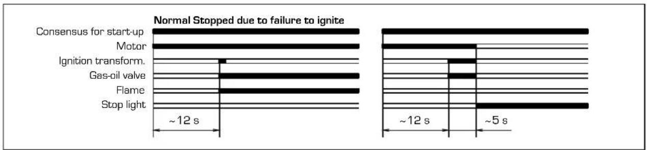
bar
| State / Condition | Time (s) | | --------------------------- | -------- | | Consensus for start-up | ~12 | | Motor | ~5 | | Ignition transform. | ~5 | | Gas-oil valve | ~5 | | Flame | ~5 | | Stop light | ~5 |3 CHARACTERISTICS
3.1 COMBUSTION CHAMBER DIMENSIONS
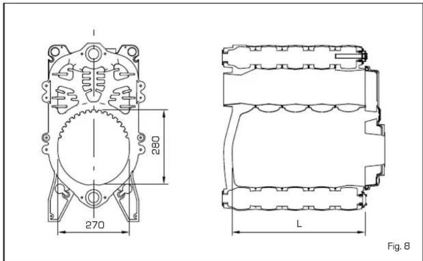
The combustion chamber is a direct passage type and is conform to the pr EN 303-3 standard annex E. The dimensions are shown in fig. 8.
| Lmm | Volumedms | |
| AQUA 30 INOX | 405 | 24,0 |
| AQUA 40 INOX | 505 | 30,5 |
3.2 SYSTEM AVAILABLE HEAD
The head available for the heating plant is shown as a function of the flow in graph in fig. 9.
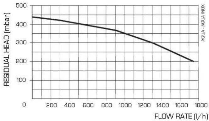
line
| FLOW RATE (l/h) | RESIDUAL HEAD (mbar) | | --------------- | -------------------- | | 0 | 450 | | 200 | 430 | | 400 | 410 | | 600 | 390 | | 800 | 370 | | 1000 | 350 | | 1200 | 320 | | 1400 | 280 | | 1600 | 240 | | 1800 | 200 |Fig. 9
4 USE AND MAINTENANCE
4.1 TIMER PROGRAMMER (optional)
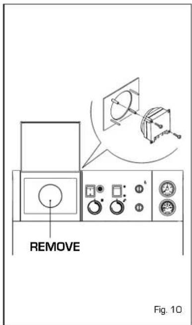
The control panel allows the use of a timer supplied in kit form upon request, complete with mounting instructions (fig. 10).
Make the electric connection as shown in point 2.6 eliminating the boiler junction-box.
4.2 TANK MAINTENANCE
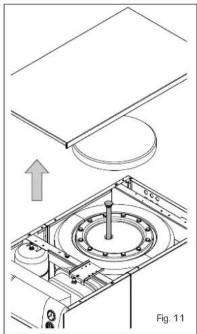
The preparation of hot treated water is guaranteed by a heater in INOX AISI 316L, complete with magnesium anode for protecting the heater and inspection flange for control and cleaning.
The magnesium anode should be periodically controlled and substituted whenever worn out (fig. 11).
natural_image
Technical diagram of a mechanical assembly with a circular component and an upward arrow, labeled Fig. 11 (no text or symbols on the diagram itself)4.3 DISASSEMBLY OF OUTER CASING
The shell can be completely disassembled for an easy maintenance of the boiler by following the numeric steps shown in fig. 12.
4.4 DISASSEMBLY OF EXPANSION VESSEL
The heating expansion tank is disassembled in the following manner:
- Make sure that the boiler has been emptied of water.
- Unscrew the union which connects the expansion tank and the two seal pins on the anchoring bracket.
Before filling up the system make sure that the expansion tank is reloaded at the pressure of 0.8 ÷ 1 bar.
4.5 BURNER MAINTENANCE
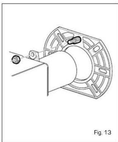
To dismantle the burner from the boiler door, remove the nut (fig. 13).
- To access the internal part of the burner, remove the air lock unit held in place by two screws to the sides and remove the right hand shell, which is held in place by four screws, taking care not to damage the O-ring seal. OR.
-
To dismantle the nozzle holder and heater unit, proceed as follows:
-
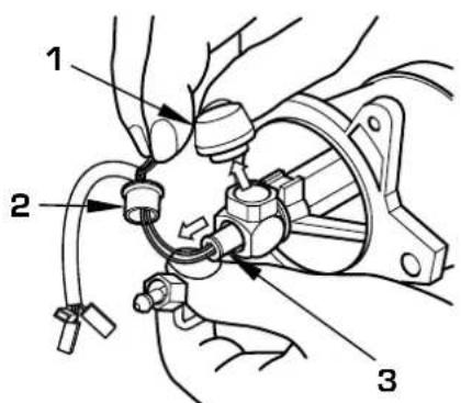
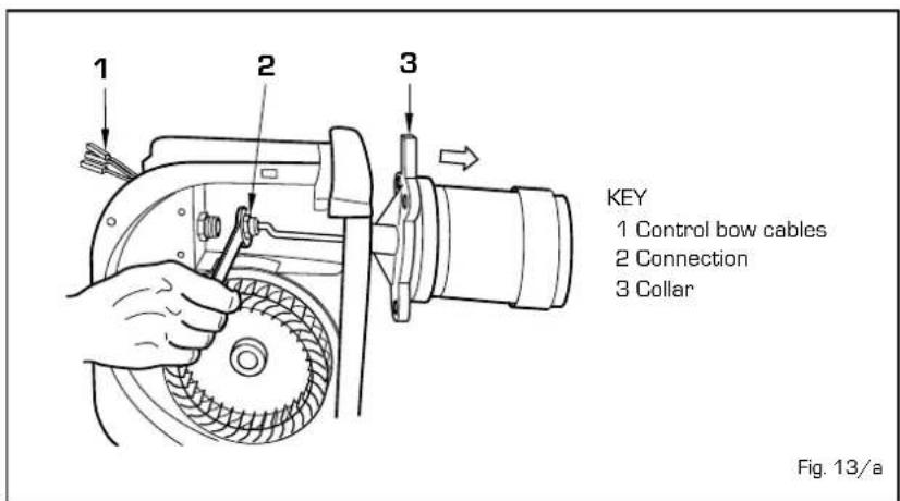
open the cover, which is held in place by a screw, and remove the heater cables (1 fig. 13/a) protected by a heat resistant sheath; remove the fairlead and pass the cables through the hole.
- remove the two cables from the ignition electrodes fastened in place with a faston.
- loosen the union (2 fig. 13/a) and remove the four screws which fas-
natural_image
Technical line drawing of a mechanical component with no visible text or symbols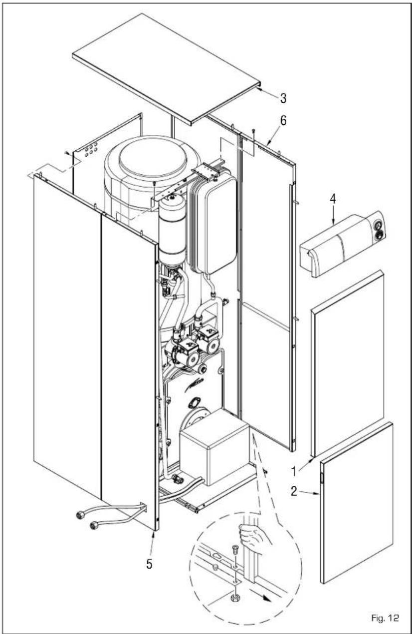
ten the collar (3 fig. 13/a) to the burner.
- To dismantle the eater or thermostat, refer to figure 13/b.
4.6 CLEANING
AND MAINTENANCE
Preventive maintenance and checking of the efficient operation of the equipment and safety devices must be carried out at the end of each heating season exclusively by the authorised technical staff.
4.6.1 Cleaning smoke ducts
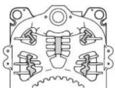
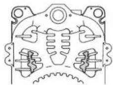
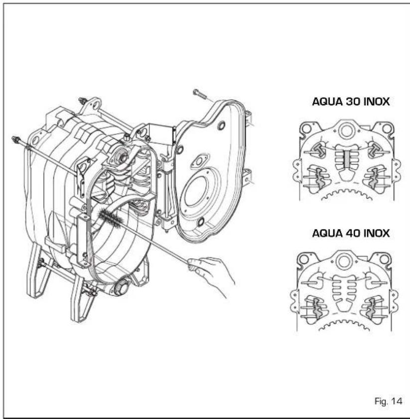
To clean exhaust passageways, remove the screws holding the door onto the boiler body, remove the turbulators and use the brush provided to clean the inner surfaces and the exhaust pipe, removing residues. When finished, put the turbulators back in position [fig. 14].
4.6.2 Cleaning combustion head
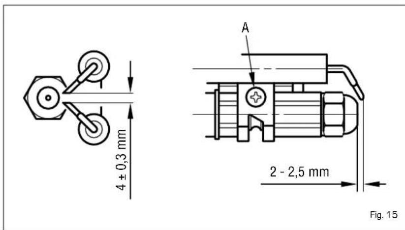
The combustion head is cleaned in the following manner (fig. 15):
- Disconnect the high tension cables from the electrodes.
- Unscrew the fixture screws of the circulator support and remove it.
- Brush the propeller delicately [turbulence disc].
- Carefully clean the photo-resistance of eventual deposits of dirt deposited on its surface.
- Clean the remaining components of the combustion head of eventual deposits.
- Upon completion re-assemble the unit in the opposite way as described above taking care to respect the indicated measurements.
4.6.3 Substitution of nozzle
The nozzle should be substituted at the beginning of every heating system for guaranteeing the correct fuel flow and a good spray efficiency.
The nozzle is substituted in the following manner:
- Disconnect the high tension cables from the electrodes.
- Loosen the fixture screw (A fig. 15) of the electrodes support and remove it.
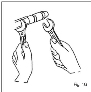
- Block the spray door using a n°19
spanner and unscrew the nozzle with a n°16 spanner (fig. 16).
natural_image
Line drawing of two hands holding wrenches, one adjusting the other (no text or symbols)4.7 FAULT FINDING
There follow a list of some reasons and the possible remedies for a series of faults which could happen causing a failure or an irregular function of the appliance. A function fault, in most cases, causes the "lock out" signal on the control panel to turn on. When this light turns on, the burner can only function again after the reset button has been pressed; once this has been done and a regular ignition occurs, the failure can be defined momentary and not dangerous.
On the contrary, if the "lock out" persists, then the cause of the fault as well as the remedy must be looked for in the following faults:
The burner does not ignite
- Check the electric connections.
- Check the regular fuel flow, the cleanness of the filters, of the nozzle and air vent from the tube.
- Check the regular spark ignition and the proper function of the burner.
The burner ignites regularly but the flame goes out immediately
- Check the flame detection, the air calibration and the function of the appliance.
Difficulty in regulating the burner and/or lack of yield
- Check: the regular flow of fuel, the cleanness of the boiler, the non obstruction of the smoke duct, the real input supplied by the burner and its cleanness (dust).
The boiler gets dirty easily
- Check the burner regulator (smoke analysis), the fuel quantity, the flue
obstruction and the cleanness of the air duct of the burner (dust).
The boiler does not heat up
- Control the cleanness of the shell, the matching, the adjustment, the burner performances, the pre-adjusted temperature, the correct function and position of the regulation stat.
- Make sure that the boiler is sufficiently powerful for the appliance.
Smell of unburnt products
- Control the cleanness of the boiler shell and the flue, the airtightness of the boiler and of the flue ducts (door, combustion chamber, smoke ducts, flue, washers).
- Control the quality of the fuel.
Frequent intervention of the boiler shutoff valve
- Control the presence of air in the system, the function of the circulation pumps.
- Check the load pressure of the appliance, the efficiency of the expansion tanks and the valve calibration.
WARNINGS
- In case of fault and/or incorrect operation, deactivate it without making any repairs or taking any direct action. If fuel or combustion is smelt, air the room and close the fuel interception device. Contact the authorised technical staff.
- The installation of the boiler and any servicing or maintenance job must be carried out by qualified personnel.
- It is absolutely prohibited to block the intake grilles and the aeration opening of the room where the equipment is installed. The intake grilles are indispensable for a correct combustion.
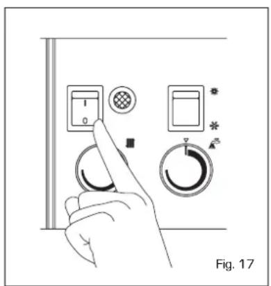
Press the main switch for lighting the boiler (fig. 17) and choose the position Summer/Winter on the switch (fig. 18):
- The boiler operates in treated phase with the switch in the position (SUMMER)
- The boiler operates both in treated
phase as well as for heating with the switch in the position (WIN-TER). The room stat or the chrono-stat will stop the operation of the boiler.
TEMPERATURE ADJUSTMENT
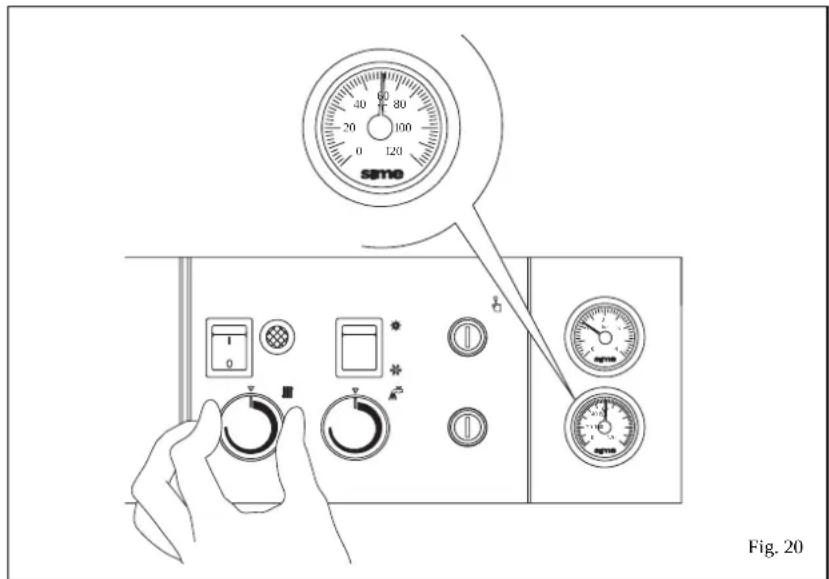
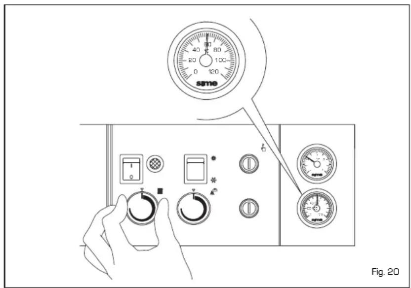
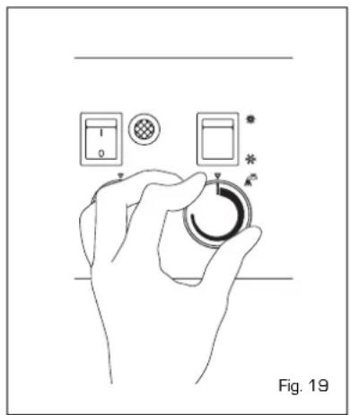
- The heating temperature can be adjusted by turning the knob of the thermostat (fig. 19).
- The heating temperature can be adjusted by turning the knob of the thermostat which has a range of between 45 and 85^ .
The temperature setting can be checked on the thermometer. To ensure optimal boiler efficiency at all times, we recommend not to
drop below a minimum working temperature of 60°C (fig. 20).
natural_image
Illustration of a hand holding a circular device with control panel and indicator lights (no text or symbols)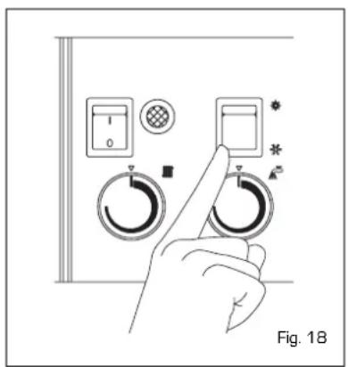
natural_image
Hand pressing a button on a control panel with circular gauges and indicator lights (no text or symbols visible)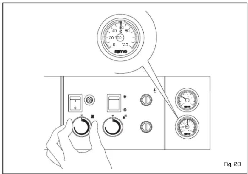
SAFETY STAT
The safety stat is of the manually resetting type and opens, causing the main burner to turn off immediately, whenever the temperature of 110^ C is exceeded in the boiler. To restore boiler operation, unscrew the black cap and reset the button (fig. 21).
Should the appliance "lock out" again, please approach the authorised technical staff.
BURNER RESTART
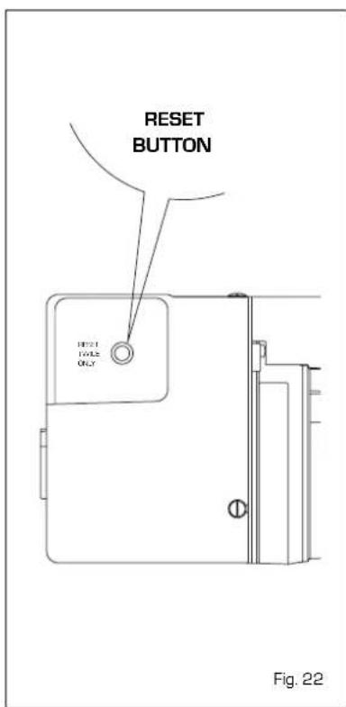
In case that ignition or operation faults occur, the main burner "locks out" and the red lamp lights up on the control panel. Press the "RESET" button to restart the ignition conditions until the flame lights up (fig. 22). This operation can be repeated 2-3 times at maximum and in case of failure contact the authorised technical staff.
ATTENTION: Make sure that there is fuel in the tank and that the taps are open. After each fill up of the tank it is advisable to interrupt the operation of the burner for about one hour.
TURNING OFF BOILER
It is sufficient to press the main switch
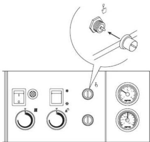
Fig. 21
to turn off the boiler (fig. 17).
Close both the gas-feed pipe tap and the water tap if the boiler remains inoperative for a long period.
SYSTEM FILLING
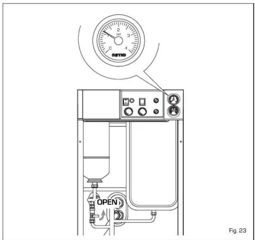
Check periodically that the hydrometer has pressure values at a switched-off system of 1 - 1.2 bar. If the pressure is less than 1 bar, re-charge it rotating the knob anti-clockwise.
After the operation check that the tap is properly closed (fig. 23).
Should the pressure exceed the foreseen limit, discharge the superfluous amount by operating on the vent knob of any radiator.
CLEANING AND MAINTENANCE
At the end of each heating season, it is essential to have the boiler thoroughly checked and cleaned out.
Preventive maintenance and checking of the efficient operation of the equipment and safety devices must be carried out exclusively by the authorised technical staff.
INSTRUCTIONS DESTINEES A L'INSTALLATEUR
TABLE DES MATIERES
1 DESCRIPTION DE LA CHAUDIERE 64
2 INSTALLATION 67
3 CARACTERISTIQUES 71
4 UTILISATION ET ENTRETIEN 71
LEGENDE
LEGENDE
1 Corps chaudière
2 Hidromètre
4 Pompe installation
5 Pompe ballon
6 Soupape de retenue
2.4 AMENEE DU COMBUSTIBLE
natural_image
Technical diagram of a mechanical assembly with a central rotating component and an upward arrow, labeled Fig. 11 (no text or symbols on the diagram itself)natural_image
Technical line drawing of a mechanical component with no visible text or symbols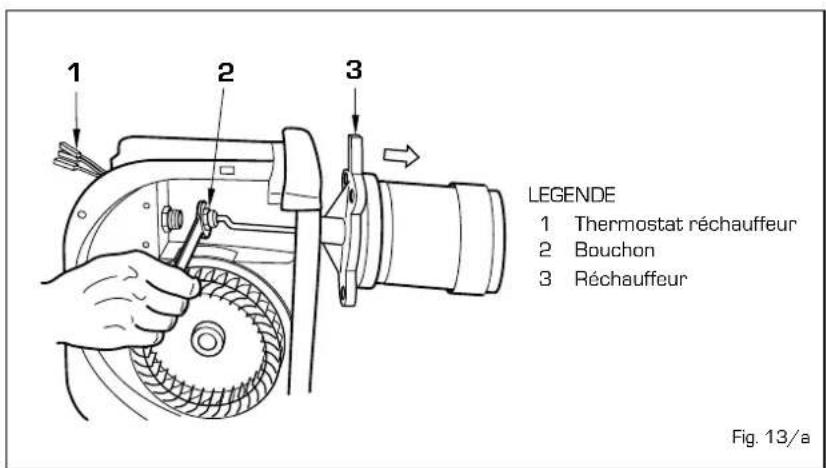
natural_image
Line drawing of two hands holding wrenches, one adjusting the other (no text or symbols)4.8 ANOMALIES DE FONCTIONNEMENT
natural_image
Illustration of a hand holding a circular device with control panel and indicator lights (no text or symbols)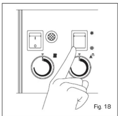
natural_image
Hand pressing a button on a control panel with dials and indicators (no text or symbols visible)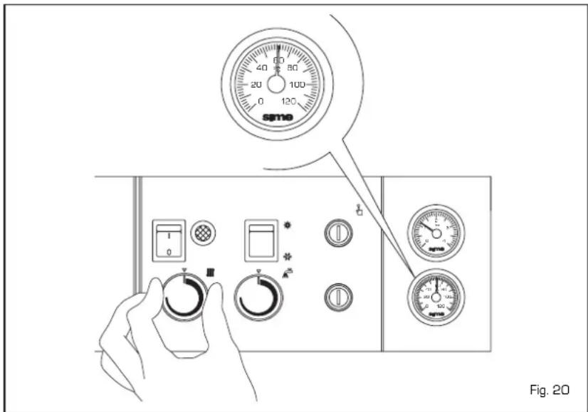
AQUASTAT DE SECURITE
natural_image
Technical line drawing of a mechanical component with mounting holes and a central shaft (no text or symbols)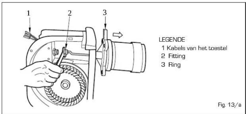
natural_image
Illustration of two hands using a wrench to adjust a mechanical component (no text or symbols present)4.7 STORINGEN IN DE WERKING
Fig. 21
DE KETEL UITSCHAKELEN
- Aqua INOX
- ISTRUZIONI PER L'INSTALLATORE
- INDICE
- PULIZIA E MANUTENZIONE CALDAIA
- TERMOSTATO SICUREZZA
- SPEGNIMENTO CALDAIA
- LEYENDA
- TERMOSTATO DE SEGURIDAD
- DADOS TECNICOS
- LEGENDA
- TERMOSTATO DE SEGURANÇA
- DESCRIPTION OF THE BOILER
- INTRODUCTION
- DIMENSIONS
- MAIN COMPONENTS
- KEY
- FUNCTIONAL DIAGRAM
- INSTALLATION
- BOILER ROOM
- CONNECTING UP SYSTEM
- System filling (fig. 4)
- Characteristics of feedwater
- CONNECTING UP FLUE
- FUEL ADDUCTION
- Important
- Starting the pump
- CONNECTIONS
- ATTENTION:
- BURNER ADJUSTMENTS
- Air lock adjustment
- Pump pressure adjustment
- HEATER UNIT
- ELECTRICAL CONNECTION
- CHARACTERISTICS
- COMBUSTION CHAMBER DIMENSIONS
- SYSTEM AVAILABLE HEAD
- USE AND MAINTENANCE
- TIMER PROGRAMMER (optional)
- TANK MAINTENANCE
- DISASSEMBLY OF OUTER CASING
- DISASSEMBLY OF EXPANSION VESSEL
- BURNER MAINTENANCE
- CLEANING
- AND MAINTENANCE
- Cleaning smoke ducts
- Cleaning combustion head
- Substitution of nozzle
- FAULT FINDING
- The burner does not ignite
- The boiler does not heat up
- Smell of unburnt products
- WARNINGS
- TEMPERATURE ADJUSTMENT
- SAFETY STAT
- BURNER RESTART
- TURNING OFF BOILER
- SYSTEM FILLING
- CLEANING AND MAINTENANCE
- INSTRUCTIONS DESTINEES A L'INSTALLATEUR
- TABLE DES MATIERES
- LEGENDE
- AMENEE DU COMBUSTIBLE
- ANOMALIES DE FONCTIONNEMENT
- AQUASTAT DE SECURITE
- STORINGEN IN DE WERKING
- DE KETEL UITSCHAKELEN
Brand : SIME
Model : Aqua INOX
Category : Boiler