Speed S+plus - Juicer Zumex - Free user manual and instructions
Find the device manual for free Speed S+plus Zumex in PDF.

| Brand | Zumex |
| Model | Speed S+plus |
| Product type | Professional citrus juicer |
| Dimensions (W × D × H) | 593 × 665 × 1050 mm |
| Net weight | 83.5 kg |
| Power supply | 220-240 V ~ 50/60 Hz (other voltages available) |
| Rated power | 460 W (560 W with optional cooler) |
| Current consumption | 2 A (2.4 A with cooler) |
| Pressing capacity | 37 to 40 oranges per minute |
| Compatible fruit types | Oranges, mandarins, lemons, grapefruits |
| Fruit size | 65 to 81 mm (45 to 67 mm with optional S kit) |
| Hopper capacity | 20 kg |
| Protection | IPX4 (protection against water splashes) |
| Noise level | Less than 70 dB(A) |
| Operating modes | Automatic, Professional, Manual (emergency) |
| Main functions | Continuous or quantity pressing, orange counter, automatic PulpOut system (optional), multifunction tap with free flow, digital display with configuration menu |
| Maintenance and cleaning | Plastic parts dishwasher-safe; daily cleaning recommended with Zumex Citric Active detergent; easy disassembly of the pressing unit (Kit 1Step) |
| Safety | Safety cover with presence detection, bin detection, emergency stop via OFF button or disconnection, overcurrent protection |
| Spare parts and repairability | Numerous accessories and spare parts available: Kit 1Step, taps, bins, filters, PulpOut systems, S/L calibration kits, display units, etc. |
| General information | Designed for intensive use in restaurants, cafeterias and supermarkets; black or mirror finishes; optional podium with Drain&Clean system; EU declaration of conformity |
Frequently Asked Questions - Speed S+plus Zumex
User questions about Speed S+plus Zumex
0 question about this device. Answer the ones you know or ask your own.
Ask a new question about this device
Download the instructions for your Juicer in PDF format for free! Find your manual Speed S+plus - Zumex and take your electronic device back in hand. On this page are published all the documents necessary for the use of your device. Speed S+plus by Zumex.
USER MANUAL Speed S+plus Zumex
Speed Up | Speed S+plus
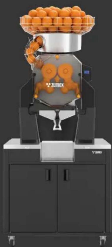
natural_image
3D rendering of a Zumex industrial machine with orange juice tray and control panel (no text or symbols visible)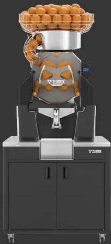
natural_image
Modern Zumex machine with orange juice tray and control panel (no visible text or symbols)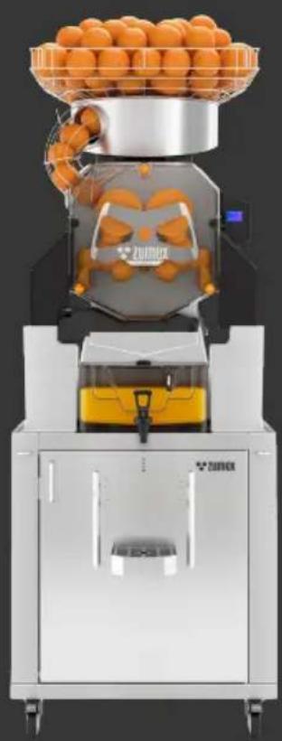
natural_image
Exterior view of a modern automated food processing machine with orange juice and a tray (no visible text or symbols)User's Manual

zumex®

bar
| Category | Value | |---|---| | Category 1 | 100 | | Category 2 | 100 | | Category 3 | 100 | | Category 4 | 100 | | Category 5 | 100 | | Category 6 | 100 | | Category 7 | 100 | | Category 8 | 100 | | Category 9 | 100 | | Category 10 | 100 | | Category 11 | 100 | | Category 12 | 100 | | Category 13 | 100 | | Category 14 | 100 | | Category 15 | 100 | | Category 16 | 100 | | Category 17 | 100 | | Category 18 | 100 | | Category 19 | 100 | | Category 20 | 100 | | Category 21 | 100 | | Category 22 | 100 | | Category 23 | 100 | | Category 24 | 100 | | Category 25 | 100 | | Category 26 | 100 | | Category 27 | 100 | | Category 28 | 100 | | Category 29 | 100 | | Category 30 | 100 | | Category 31 | 100 | | Category 32 | 100 | | Category 33 | 100 | | Category 34 | 100 | | Category 35 | 100 | | Category 36 | 100 | | Category 37 | 100 | | Category 38 | 100 | | Category 39 | 100 | | Category 40 | 100 | | Category 41 | 100 | | Category 42 | 100 | | Category 43 | 100 | | Category 44 | 100 | | Category 45 | 100 | | Category 46 | 100 | | Category 47 | 100 | | Category 48 | 100 | | Category 49 | 100 | | Category 50 | 100 | | Category 51 | 100 | | Category 52 | 100 | | Category 53 | 100 | | Category 54 | 100 | | Category 55 | 100 | | Category 56 | 100 | | Category 57 | 100 | | Category 58 | 100 | | Category 59 | 100 | | Category 60 | 100 | | Category 61 | 100 | | Category 62 | 100 | | Category 63 | 100 | | Category 64 | 100 | | Category 65 | 100 | | Category 66 | 100 | | Category 67 | 100 | | Category 68 | 100 | | Category 69 | 100 | | Category 70 | 100 | | Category 71 | 100 | | Category 72 | 100 | | Category 73 | 100 | | Category 74 | 100 | | Category 75 | 100 | | Category 76 | 100 | | Category 77 | 100 | | Category 78 | 100 | | Category 79 | 100 | | Category 80 | 100 | | Category 81 | 100 | | Category 82 | 100 | | Category 83 | 100 | | Category 84 | 100 | | Category 85 | 100 | | Category 86 | 100 | | Category 87 | 100 | | Category 88 | 100 | | Category 89 | 100 | | Category 90 | 100 | | Category 91 | 100 | | Category 92 | 100 | | Category 93 | 100 | | Category 94 | 100 | | Category 95 | 100 | | Category 96 | 100 | | Category 97 | 100 | | Category 98 | 100 | | Category 99 | 100 | | Total (Total) |Index
User's manual → 36
Drawing and description
SS: Self Service / Self Service All-in-One. Tank: Tank All-in-One. Cooler: Cooler Podium.
Speed Up
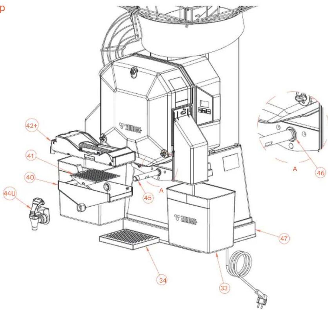
Fig. 3U
| EN | ES | FR | DE | IT | |
| 33 | PEEL BUCKET | CUBETA CORTEZAS | BAC À DÉCHETS | SCHALENBEHÄLTER | VASCHETTA BUCCE |
| 34 | DRIP TRAY | BANDEJA GOTEO | BAC ANTIGOUTTES | TROPFAUFFANGSCHALE | VASCHETTA RACCOGLIGOCCE |
| 40 | SS JUICE CONTAINER | CUBETA ZUMO SS | BAC À JUS SS | SS SAFTBEHÄLTER | VASCHETTA SUCCO SS |
| 4 | SS SUB-FILTER | SUBFILTRO SS | SOUS-FILTRE SS | SS UNTERFILTER | SOTTOFILTRO SS |
| 42+ | AUTOMATIC PULPOUT SYSTEM | SISTEMA PULPOUT AUTOMÁTICO | SYSTÈME PULPOUT AUTOMATIQUE | AUTOMATISCHES PULPOUT-SYSTEM | SISTEMA PULPOUT AUTOMATICO |
| 44L | SS UP TAP | GRIFO SS UP | ROBINET SS UP | SS-HAHN UP | RUBINETTO SS UP |
| 45 | TAP DETECTOR TUBE | TUBO DETECTOR DE GRIFO | TUBE DÉTECTEUR DE NIVEAU ROBINET | SENSORROHR HAHN | TUBO SENSORE DI RUBINETTO |
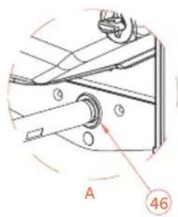
| 46 | DETECTOR TUBE GASKET | JUNTA TUBO DETECTOR | JOINT TUBE DÉTECTEUR | DICHTUNG SENSORROHR | GUARNIZIONE TUBO SENSORE |
| 47 | MACHINE SUPPLEMENT | SUPLEMENTO MÁQUINA | ACCESSOIRE DE LEVAGE MACHINE | ERGÄNZUNGSTEIL MASCHINE | SUPPLEMENTO MACCHINA |
Speed S +plus
Fig. 3+
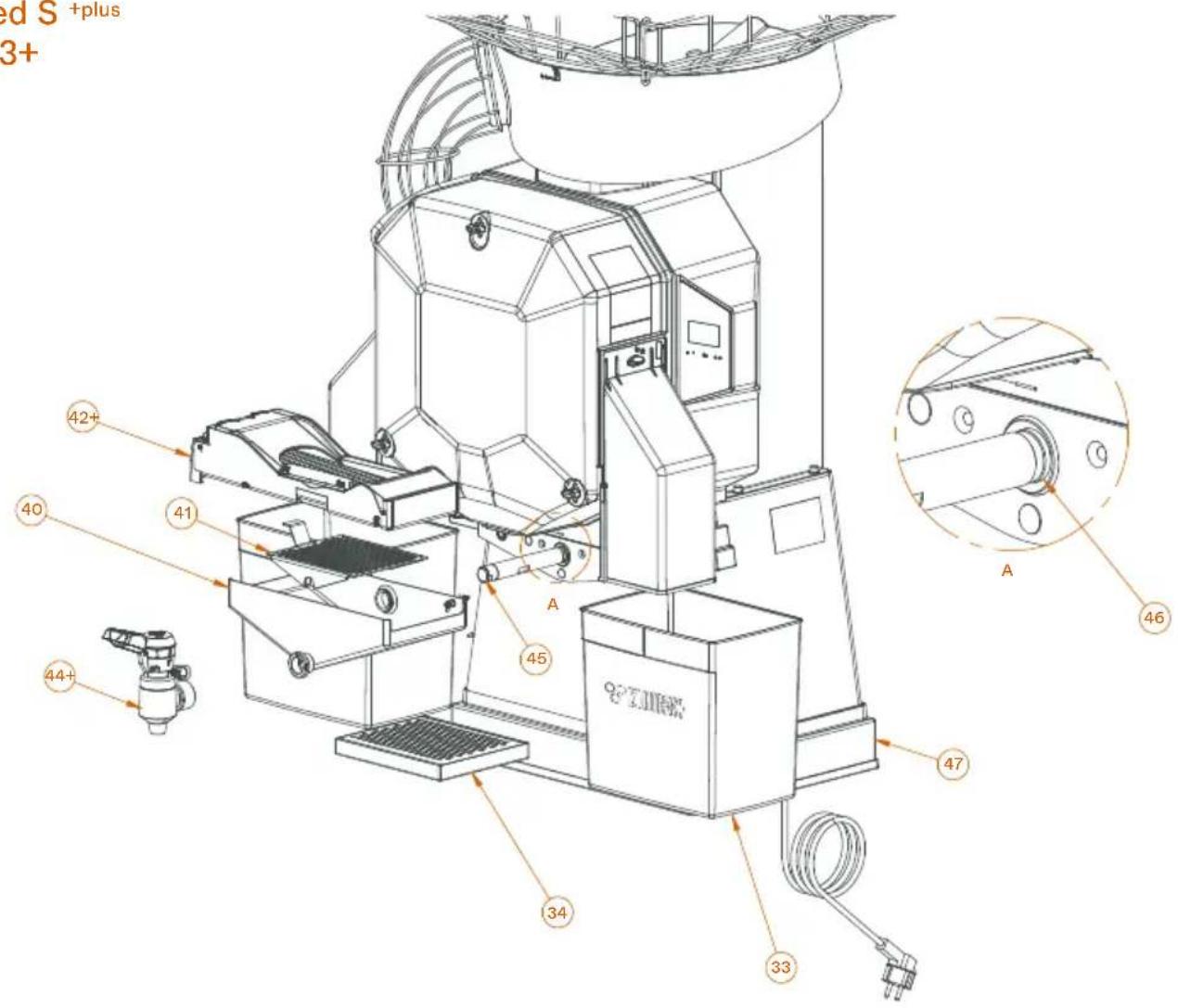
| EN | ES | FR | DE | IT | |
| 42+ | AUTOMATIC PULPOUT | SISTEMA PULPOUT AUTOMÁTICO | SYSTÈME PULPOUT | AUTOMATISCHES PULPOUT-SYSTEM | SISTEMA PULPOUT AUTOMATICO |
| 44+ | SYSTEM | GRIFO SS S +PLUS | AUTOMATIQUE | SS-HAHN S +PLUS | RUBINETTO SS S +PLUS |
| SS S +PLUS TAP | ROBINET SS S +PLUS |
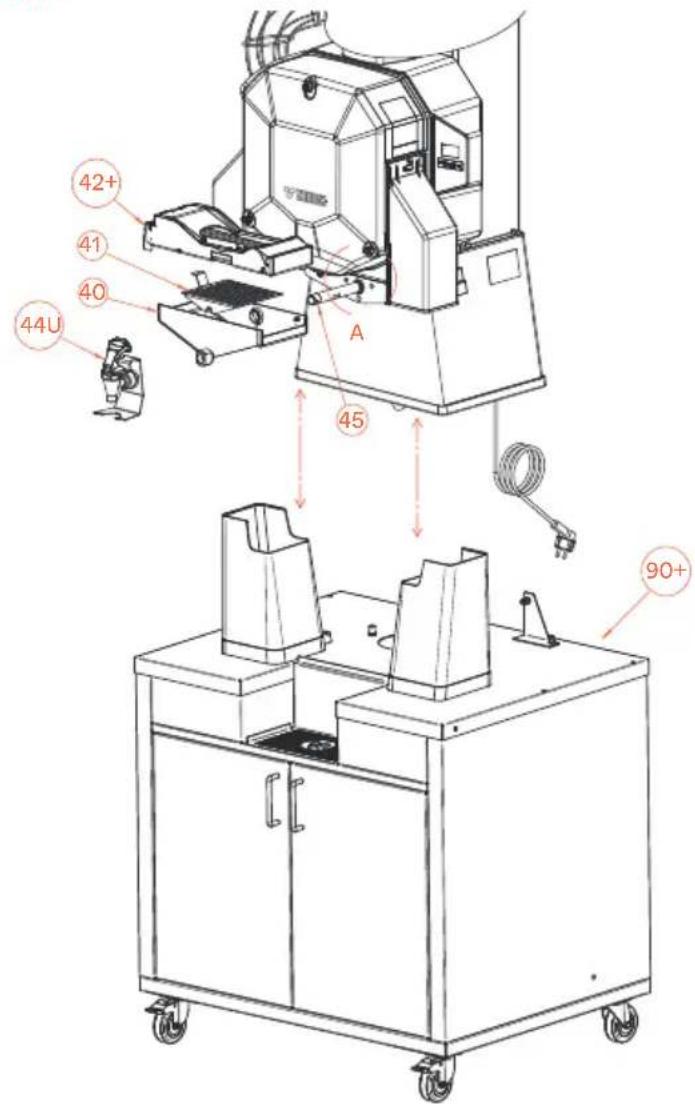
Speed Up All-in-One
Fig. 4U
Z
| 40 | SS JUICE CONTAINER | CUBETA ZUMO SS | BAC À JUS SS | SS SAFTBEHÄLTER | VASCHETTA SUCCO SS |
| 41 | SS SUB-FILTER | SUBFILTRO SS | SOUS-FILTRE SS | UNTERFILTER SS | SOTTOFILTRO SS |
| 42+ | AUTOMATIC PULPOUT | SISTEMA PULPOUT | SYSTÈME PULPOUT | A U T O M A T I S C H E S | SISTEMA PULPOUT AUTOMATICO |
| 44U | SYSTEM | AUTOMÁTICO | AUTOMATIQUE | PULPOUT-SYSTEM | RUBINETTO SS UP |
| 45 | SS UP TAP | GRIFO SS UP | ROBINET SS UP | SS-HAHN UP | TUBO SENSORE DI RUBINETTO |
| 46 | TAP DETECTOR TUBE | TUBO DETECTOR DE | TUBE DÉTECTEUR DE NIVEAU | SENSORROHR HAHN | GUARNIZIONE TUBO SENSORE |
| 90+ | DETECTOR TUBE | GRIFO | ROBINET | DICHTUNG SENSORROHR | PODIUM UP |
| GASKET | JUNTATUBO DETECTOR | JOINT TUBE DÉTECTEUR | PODIUM UP | ||
| UP PODIUM | PODIUM UP | PODIUM UP |
ES
FR
DE
上
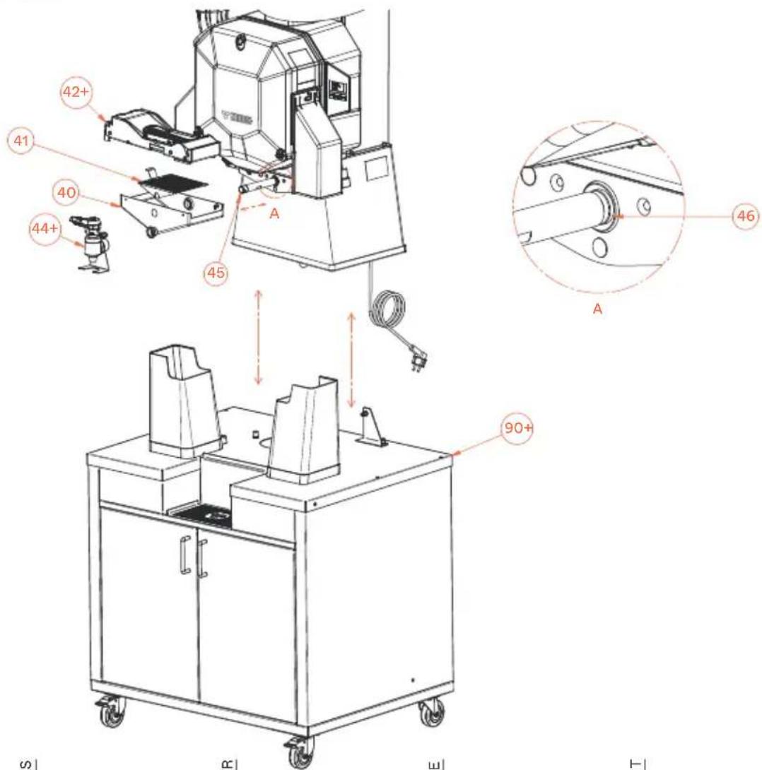
Speed S All-in-One
Fig. 4+
Z
42+ AUTOMATIC PULPOUT
44+ SYSTEM
90+ SS S +PLUS TAP
SS PODIUM S +PLUS
ES
SISTEMA PULPOUT
AUTOMÁTICO
GRIFO SS S +PLUS
PODIUM SS S +PLUS
FR
SYSTÈME PULPOUT
AUTOMATIQUE
ROBINET SS S +PLUS
PODIUM SS S +PLUS
DE
AUTOMATISCHES
PULPOUT-SYSTEM
SS-HAHN S +PLUS
PODIUM SS S +PLUS
上
SISTEMA PULPOUT AUTOMATICO
RUBINETTO SS S +PLUS
PODIUM SS S +PLUS
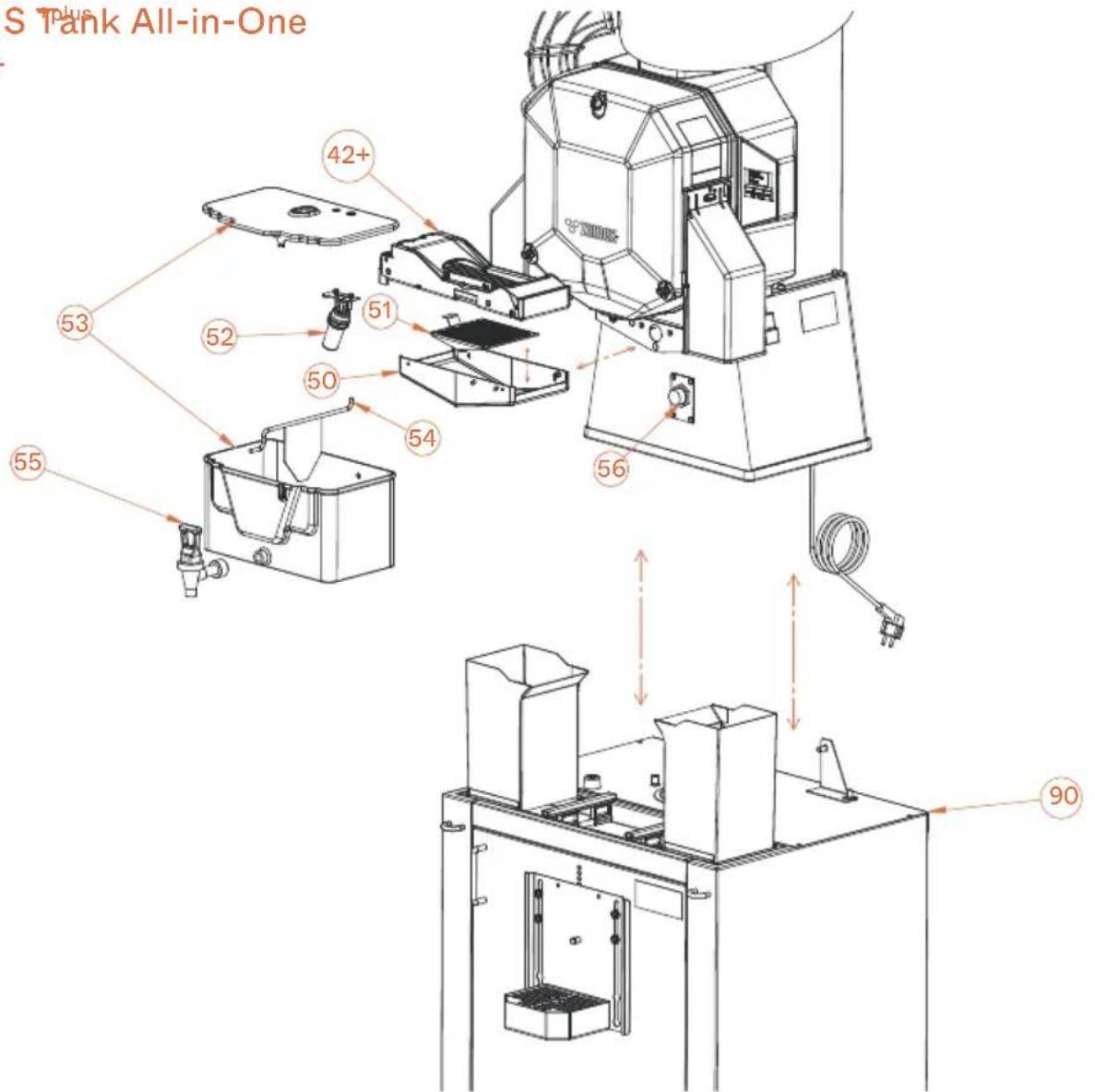
Speed S Tank All-in-One
Fig. 5+
Z
+
AUTOMATIC PULPOUT
SYSTEM
TANK JUICE CONTAINER
TANK SUB-FILTER
TANK/COOLER BUOY
TANK
SHAKER
TANK TAP
LEVEL DETECTOR
SS/TANK PODIUM
ES
SISTEMA PULPOUTAUTOMÁTICO
CUBETA ZUMO TANK
SUBFILTRO TANK
BOYATANK/COOLER
TANK
AGITADOR
GRIFO TANK
DETECTOR DE NIVEL
PODIUM SS/TANK
FR
SYSTÈME PULPOUT AUTOMATIQUE
BACÀ JUS TANK
SOUS-FILTRE TANK
FLOTTEUR TANK/COOLER
TANK
MÉLANGEUR
ROBINET TANK
DÉTECTEUR DE NIVEAU
PODIUM SS/TANK
DE
AUTOMATISCHES PULPOUT-SYSTEM
SAFTBEHÄLTER TANK
UNTERFILTER TANK
SCHWIMMER TANK/COOLER
TANK
RÜHRELEMENT
HAHN TANK
FULLSTANDSENSOR
PODIUM SS/TANK
上
SISTEMA PULPOUTAUTOMATICO
VASCHETTA SUCCO TANK
SOTTOFILTRO TANK
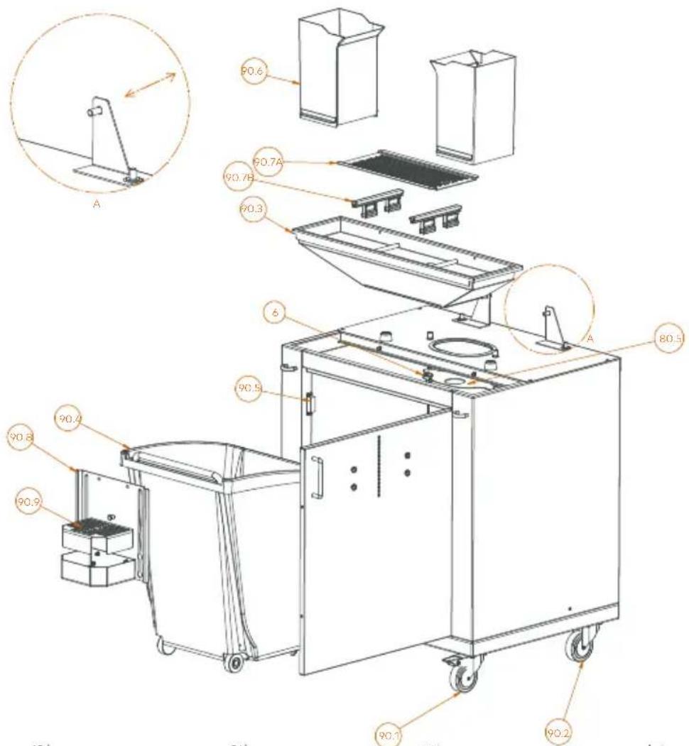
Podium (Speed S +plus Tank All-in-One)
Fig. 8
Z
| 6 | PLASTIC SECURING KNOB | VOLANTE PLÁSTICO INYECCIÓN | ECROU PAPILLON PLASTIQUE INJECTION | SICHERHEITSSCHRAUBE SPRITZGUSSKUNSTSTOFF | VITE DI SICUREZZA PLASTICA INIEZIONE |
| 80.5 | SS/TANK STAND COVER | TAPA MUEBLE TANK-SS | PLAQUE MEUBLE SS/TANK | UNTERSCHRANKDECKEL SS/TANK | COPERCHIO MOBILE SS/TANK |
| 90.1 | SWIVEL WHEEL WITH BRAKE | RUEDA GIRATORIA CON FRENO | ROUE TOURNANTE AVEC FREIN | CHWENKROLLE MIT BREMSE | RUOTA GIREVOLE CON FRENO |
| 90.2 | SWIVEL WHEEL WITHOUT BRAKE | RUEDA GIRATORIA SIN FRENO | ROUE TOURNANTE SANS FREIN | SCHWENKROLLE OHNE BREMSE | RUOTA GREVOLE SENZA FRENO |
| 90.3 | STAND HOPPER | TOLVA MUEBLE | ENTONNOIR MEUBLE | TRICHTER UNTERSCHRANK | TRAMOGGA MOBILE |
| 90.4 | WASTE BIN | CARRITO RESIDUOS | CHARRIOT À DÉCHETS | ABFALLWACEN | CARRELLO SCARTI |
| 90.5 | DOOR LOCK MAGNET | IMÁN CIERRE PUERTA | AIMANT FERMETURE PORTE | TÜRVERSCHLUSSMAGNET | CALAMITA CHILISURA SPORTELLO |
| 90.6 | PEEL OUTLET | CAÍDA CORTEZAS | RÉCUPÉRATEUR DECHETS | SCHALENAUSTRITT | CADUTA BUCCE |
| 90.7 A | SS STAND FILTER | FILTRO MUEBLE SS | FILTRE MEUBLE SS | FILTER UNTERSCHRANK SS | FILTRO MOBILE SS |
| 90.7 B | TANK GUIDES | GUIAS DEPÓSITO TANK | GUIDES TANK | BEHÄTERFUHRUNGEN TANK | GUIDA SERBATOIO TANK |
| 90.8 | TRAY FRONT | FRONTIS BANDEJA | PLAQUE FACE BAC | FRONTBLENDE TABLETT | FRONTALINO VASCHETTA |
| 90.9 | TRAY FILTER | FILTRO BANDEJA | FILTRE BAC | FILTER TABLETT | FILTRO VASCHETTA |
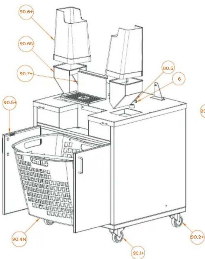
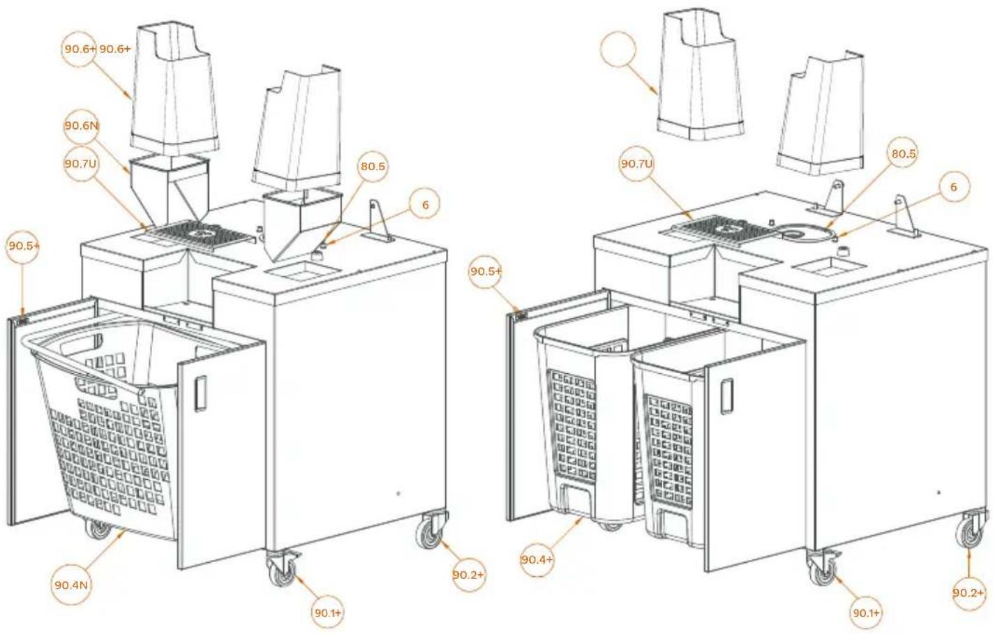
Podium Mirror (Narrow / Wide)
Fig. 8.1
EN
| € | PLASTIC SECURING KNOB | VOLANTE PLÁSTICO |
| 80.5 | SS/TANK STAND COVER | INYECCIÓN |
| 90.1+ | SWIVEL WHEEL WITH BRAKE | TAPA MUEBLE TANK-SS |
| 90.2+ | SWIVEL WHEEL WITHOUT | RUEDA GIRATORIA CON FRENO |
| 90.4+ | BRAKE | RUEDA GIRATORIA SIN FRENO |
| 90.4N | WASTE BIN | CARRITO RESIDUOS |
| 90.5+ | WASTE BIN | CARRITO RESIDUOS |
| 90.6+ | DOOR LOCK MAGNET | IMÁN CIERRE PUERTA |
| 90.6N | PEEL OUTLET | CAÍDA CORTEZAS |
| 90.7+ | PEEL OUTLET | CAÍDA CORTEZAS |
| TWO-POSITION TRAY | BANDEJA 2 POSICIONES |
ER
| ECROU PAPILLON PLASTIQUE |
| INJECTION |
| PLAQUE MEUBLE SS/TANK |
| ROUE TOURNANTE AVEC FREI |
| ROUE TOURNANTE SANS FREI |
| CHARRIOT À DÉCHETS |
| CHARRIOT À DÉCHETS |
| AIMANT FERMETURE PORTE |
| RÉCUPÉRATEUR DECHETS |
| RÉCUPÉRATEUR DECHETS |
| PLATEAU 2 POSITIONS |
DE
| SICHERHEITSSCHRAUBE |
| SPRITZGUSSKUNSTSTOFF |
| UNTERSCHRANKDECKEL SS/TANK |
| CHWENKROLLE MIT BREMSE |
| SCHWENKROLLE OHNE BREMSE |
| ABFALLWAGEN |
| ABFALLWAGEN |
| TÜRVERSCHLUSSMAGNET |
| SCHALENAUSTRITT |
| SCHALENAUSTRITT |
| TROPFSCHALE 2 POSITIONEN |
上
| VITE DI SICUREZZA PLASTICA |
| INIEZIONE |
| COPERCHIO MOBILE SS/TANK |
| RUOTA GIREVOLE CON FRENO |
| RUOTA GIREVOLE SENZA |
| FRENO |
| CARRELLO SCARTI |
| CARRELLO SCARTI |
| CALAMITA CHIUSURA |
| SPORTELLO |
| CADUTA BUCCE |
| CADUTA BUCCE |
| VASSOIO 2 POSIZIONI |
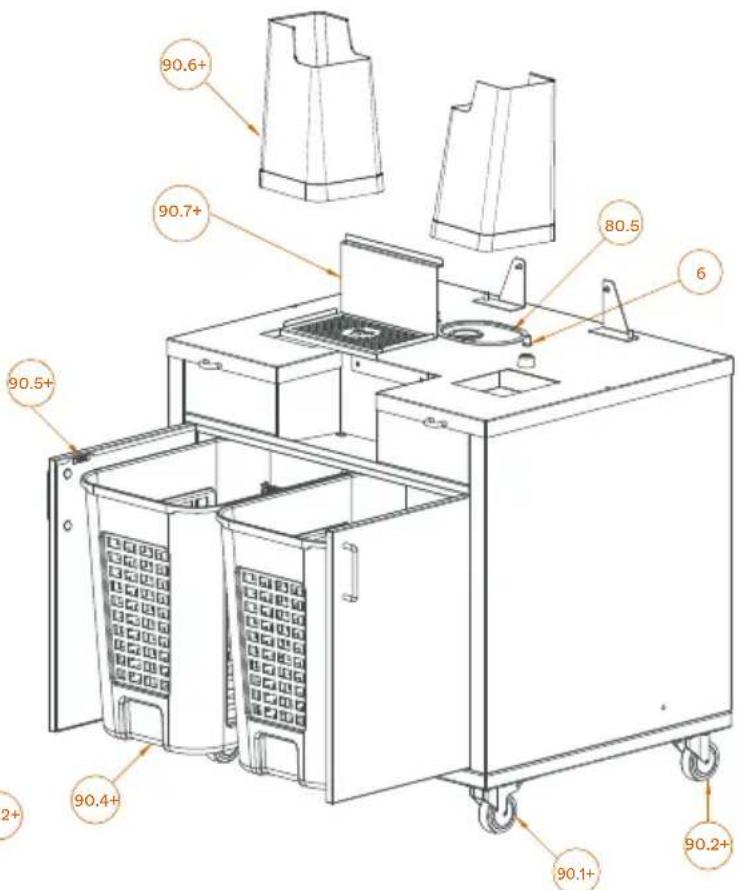
Podium Black (Narrow / Wide)
Fig. 8.2
| EN | ES | FR | DE | IT | |
| € | PLASTIC SECURING KNOB | VOLANTE PLÁSTICO INYECCIÓN | ECROU PAPILLON PLASTIQUE INJECTION | SICHERHEITSSCHRAUBE | VITE DI SICUREZZA PLASTICA |
| 80.5 | SS/TANK STAND COVER | TAPA MUEBLE TANK-SS | PLAQUE MEUBLE SS/TANK | SPRITZGUSSKUNSTSTOFF | INIEZIONE |
| 90.1+ | SWIVEL WHEEL WITH BRAKE | RUEDA GIRATORIA CON FRENO | ROUE TOURNANTE AVEC FREIN | UNTERSCHRANKDECKEL SS/TANK | COPERCHIO MOBILE SS/TANK |
| 90.2+ | SWIVEL WHEEL WITHOUT BRAKE | RUEDA GIRATORIA SIN FRENO | ROUE TOURNANTE SANS FREIN | CHWENKROLLE MIT BREMSE | RUOTA GIREVOLE CON FRENO |
| 90.4+ | WASTE BIN | CARRITO RESIDUOS | CHARRIOT À DÉCHETS | SCHWENKROLLE OHNE BREMSE | RUOTA GIREVOLE SENZA FRENO |
| 90.4N | WASTE BIN | CARRITO RESIDUOS | CHARRIOT À DÉCHETS | ABFALLWAGEN | CARRELLO SCARTI |
| 90.5+ | DOOR LOCK MAGNET | IMÁN CIERRE PUERTA | AIMANT FERMETURE PORTE | ABFALLWAGEN | CARRELLO SCARTI |
| 90.6+ | PEEL OUTLET | CAÍDA CORTEZAS | RÉCUPÉRATEUR DECHETS | TÜRVERSCHLUSSMAGNET | CALAMITACHIUSURA SPORTELLO |
| 90.6N | PEEL OUTLET | CAÍDA CORTEZAS | RÉCUPÉRATEUR DECHETS | SCHALENAUSTRITT | CADUTA BUCCE |
| 90.7U | TRAY FILTER | FILTRO BANDEJA | FILTRE BAC | SCHALENAUSTRITT | CADUTA BUCCE |
| FILTER TAPLETT | FILTRO VASCHETTA | ||||
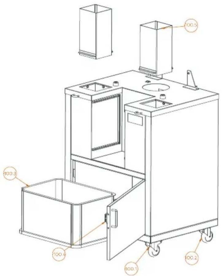
Podium (Speed Pro Cooler)
Fig. 9.1-9.2
natural_image
Line drawing of a mechanical device with wheels and two rectangular components (no text or symbols)Z
| 1001 | SWIVEL WHEEL WITH BRAKE | RUEDA GIRATORIA CON FRENO | ROUE TOURNANTE AVEC FREIN | SCHWENKROLLE MIT BREMSE | RUOTA GIREVOLE CON FRENO |
| 100.2 | SWIVEL WHEEL WITHOUT BRAKE | RUEDA GIRATORIA SIN FRENO | ROUE TOURNANTE SANS FREIN | SCHWENKROLLE OHNE BREMSE | RUOTA GIREVOLE SENZA FRENO |
| 100.3 | PEEL BUCKET | CUBO CORTEZAS | BAC À DECHETS | SCHALENEIMER | DEPOSITO BUCCE |
| 100.6 | DOOR LOCK MAGNET | IMAN CIERRE PUERTA | AIMANT FERMETURE PORTE | TÜRVERSCHLUSSMAGNET | CALAMITA CHIUSURA SPORTELLO |
| 100.5 | PEEL CHUTE | CAIDA CORTEZAS | RÉCUPÉRATEUR DECHETS | SCHALENAUSTRITT | CADUTA BUCCE |
ES
FR
DE
T
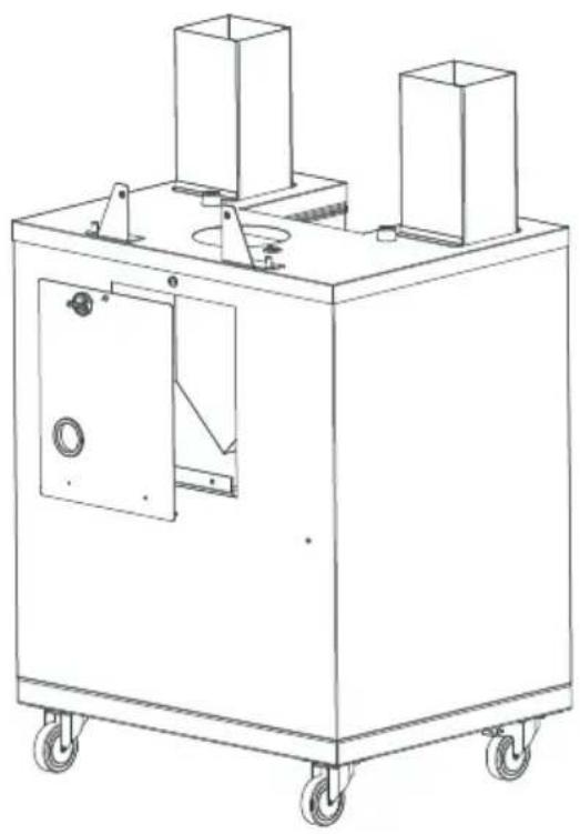
Fig. 10.1
natural_image
Line drawing of a greenhouse structure with doors, pipes, and a chimney (no text or symbols)2
natural_image
Technical line drawing of a mechanical component with mounting bracket (no text or symbols)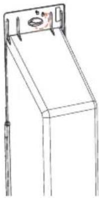
natural_image
Line drawing of a mechanical support structure with no visible text or symbols3
natural_image
Technical line drawing of a mechanical device with no visible text or symbolsFig. 10.2
natural_image
Technical line drawing of a mechanical assembly with gears and housing (no text or symbols)2
3
natural_image
Technical line drawing of a mechanical device with no visible text or symbols4
natural_image
Technical line drawing of a mechanical device with no visible text or symbolsFig. 11
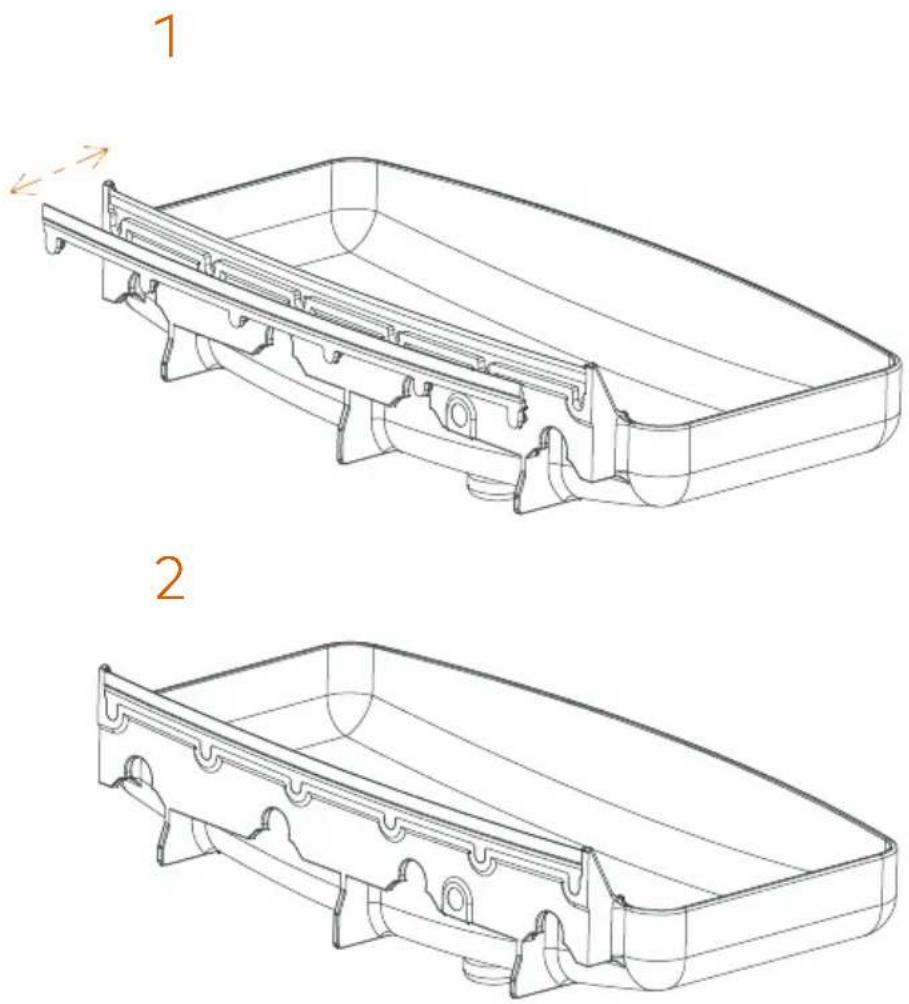
Fig. 12
natural_image
Technical line drawing of a mechanical assembly with no visible text or symbolsFig. 13.1
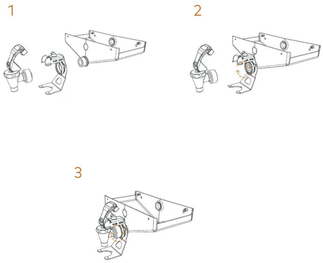
Fig. 13.2
1
natural_image
Technical line drawing of a mechanical assembly with no visible text or symbols2
natural_image
Technical line drawing of a mechanical component with no visible text or symbols3
natural_image
Technical illustration of a mechanical assembly with no visible text or symbols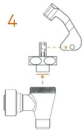
5
6
natural_image
Technical line drawing of a mechanical device with no visible text or symbolsFig. 14.1+
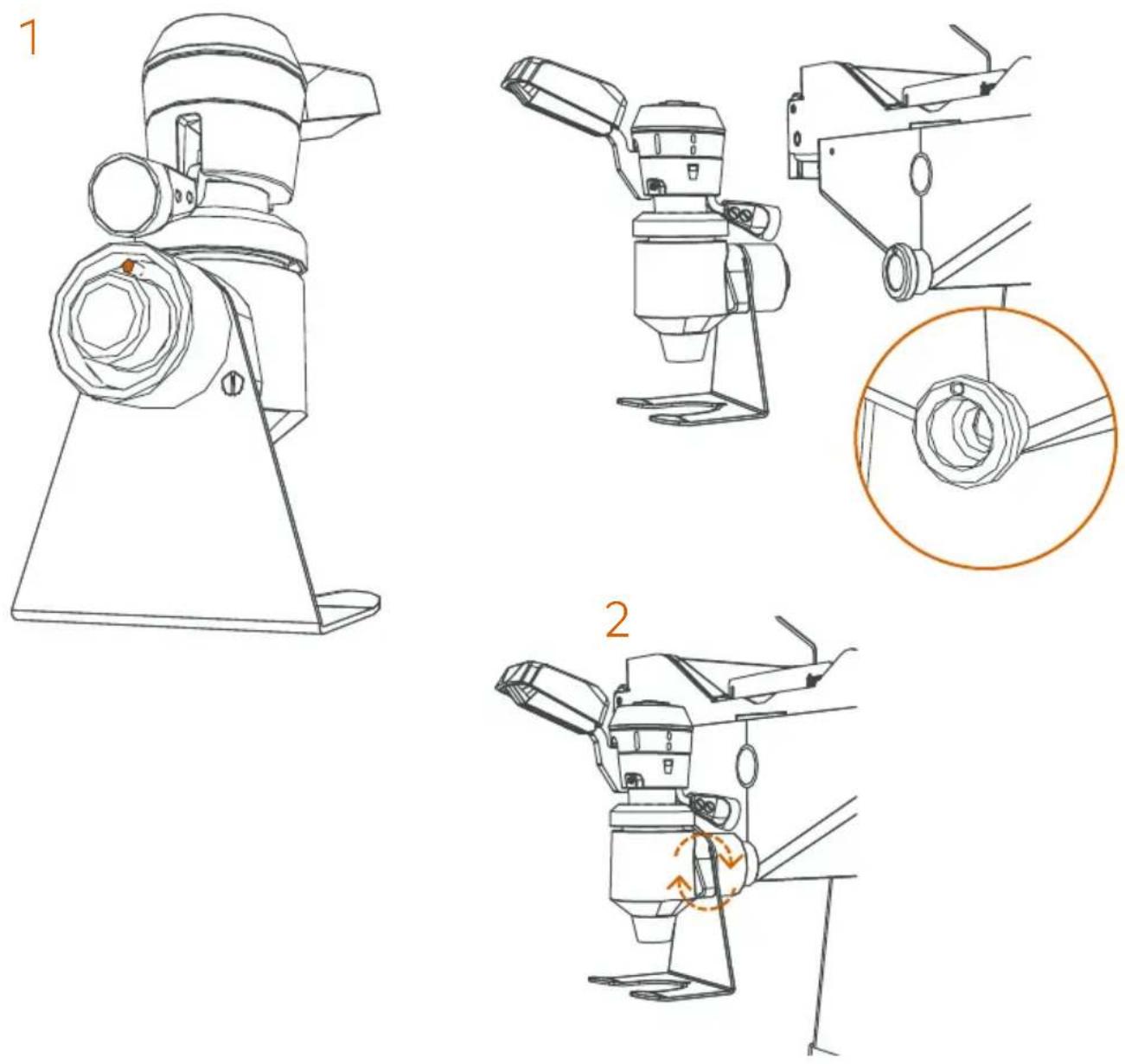
Fig. 14.2+
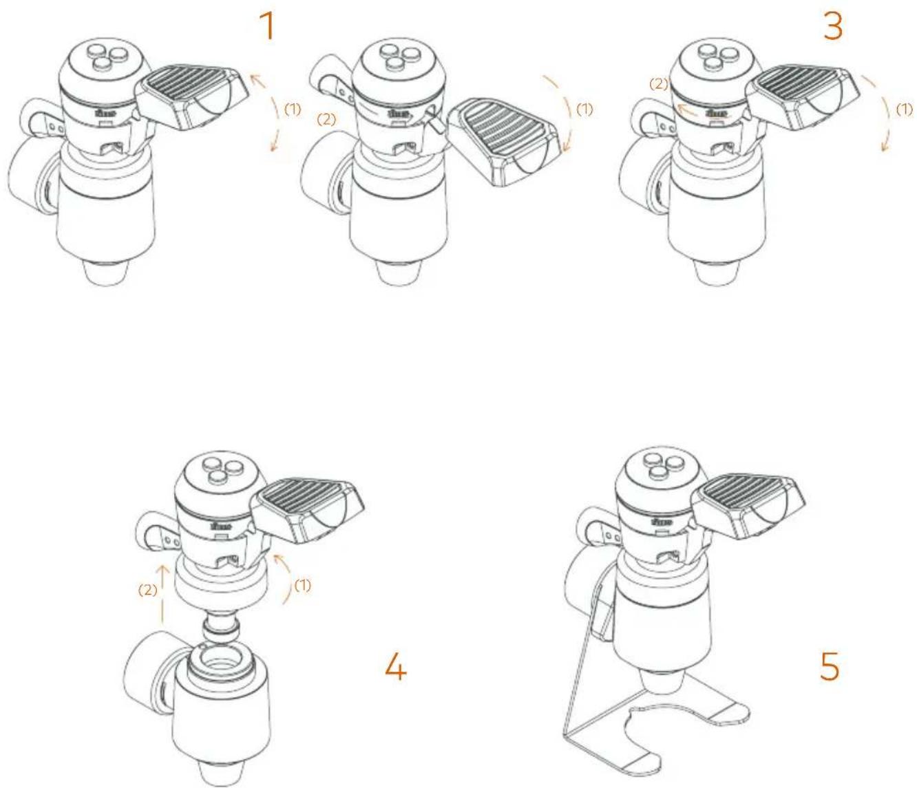
Fig. 15
natural_image
Technical line drawing of a mechanical assembly with mounting bracket, bolts, and housing (no text or symbols)Fig. 16
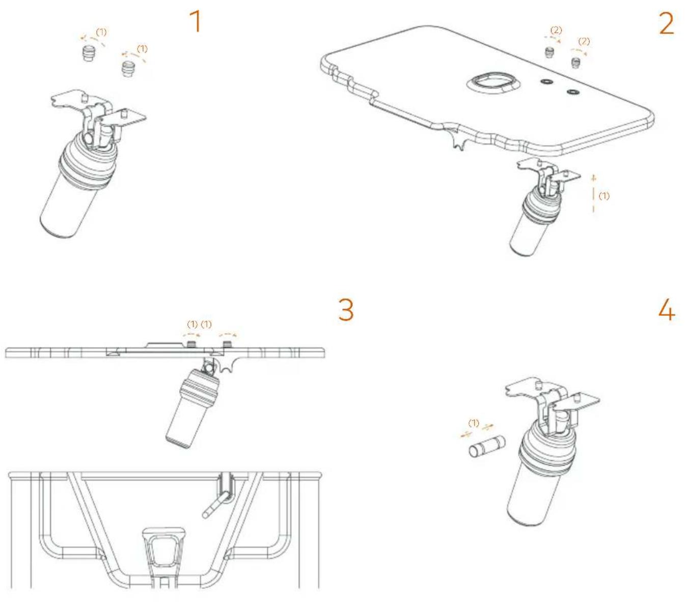
Fig. 17.1-17.2
natural_image
Technical line drawing of a mechanical device with wheels and internal components (no text or symbols)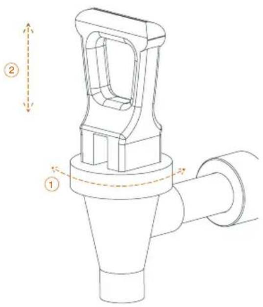
Fig. 18
| EN | ES | FR | DE | IT | |
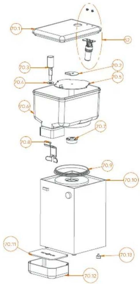
| 52 | TANK / COOLER BUOY | BOYA TANK/COOLER | FLOTTEUR TANK/COOLER | SCHWIMMER TANK/COOLER | GALLEGGIANTE TANK/COOLER |
| 70.1 | TANK COVER | TAPA DEPÓSITO | COUVERCLE RÉSERVOIR | DECKEL SAFTBEHÄTER | TAPPO SERBATOIO |
| 70.2 | COUPLER PLATE | PLACA DE ENGANCHE | PLAQUE CONNECTEUR | BEFESTIGUNGSPLATTE | PIASTRA DI ATTACCO |
| 70.3 | TAP PISTON | PISTÓN GRIFO | PISTON ROBINET | KOLBEN HAHN | PISTONE RUBINETTO |
| 70.4 | TAP GASKET | JUNTA GRIFO | JOINT ROBINET | DICHUNG HAHN | GUARNIZIONE RUBINETTO |
| 70.5 | PUMP COVER | TAPA BOMBA | COUVERCLE POMPE | DECKEL PUMPE | COPERCHIO POMPA |
| 70.6 | TANK | DEPÓSITO | RÉSERVOIR | BEHÄTER | SERBATOIO |
| 70.7 | PUMP TURBINE | TURBINA BOMBA | TURBINE POMPE | TURBINE PUMPE | TURBINA POMPA |
| 70.8 | TAP CONTROL LEVER | PALANCA MANDO GRIFO | TIRETTE DE COMMANDE ROBINET | HAHN BETÄTIGUNGSHEBEL | LEVA COMANDO RUBINETTO |
| 70.9 | TANK GASKET | JUNTA DEPÓSITO | JOINT RÉSERVOIR | DICHUNG BEHÄTER | GUARNIZIONE SERBATOIO |
| 70.10 | COOLER UNIT | UNIDAD ENFRIADORA | UNITÉ REFROIDISSEUR | KÜHLENHET | SISTEMA REFRIGERANTE |
| 70.11 | TRAY GRATING | REJILLA CAJÓN | GRILLE BAC | GITTER KASTEN | GRIGLIA VASCHETTA |
| 70.12 | DRIP TRAY H | CAJÓN RECOGE GOTAS H | BAC ANTIGOUTTES H | TROPFAUFFANGKASTEN H | VASCHETTA RACCOGLIGOCCE H |
| 70.13 | LEVELLING FOOT | PIE NIVELADOR | VIS DE REGLAGE HAUTEUR | NIVELLIERFUSS | PIEDINO LIVELLATORE |
Fig. 19+
1
natural_image
Technical line drawings of mechanical components and housing (no text or symbols)2
3
natural_image
Technical line drawing of a mechanical assembly with no visible text or symbols4
natural_image
Technical line drawing of a mechanical assembly with no visible text or symbols
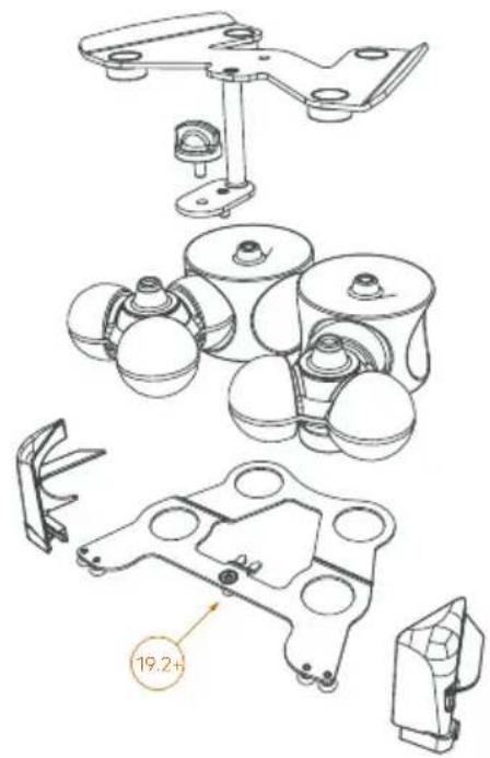
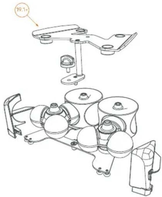
19.1+
192+

FRONT HOLDER
REAR HOLDER
SOPORTE DELANTERO
SOPORTE TRASERO

SUPPORT AVANT
SUPPORT ARRIÈRE

VORDEREN HALTER
HINTEREN HALTER

SUPPORTO ANTERIORE
SUPPORTO POSTERIORE
Fig. 20.1+
natural_image
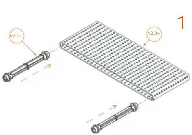
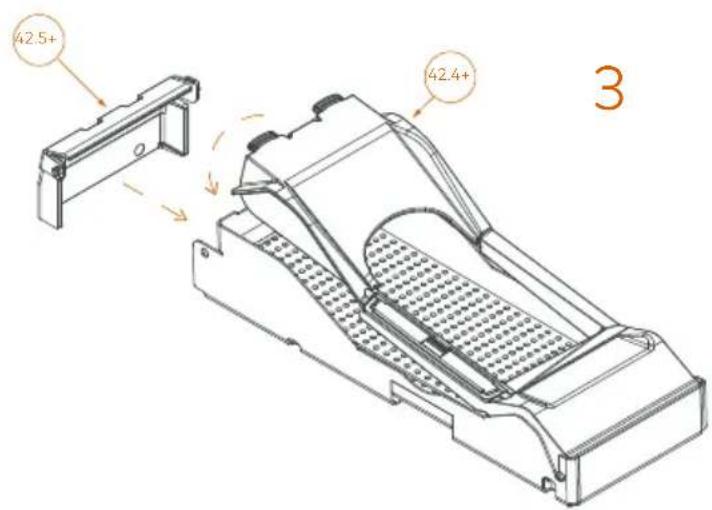
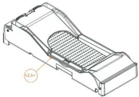
Technical line drawing of a mechanical component with a grid-patterned inner structure and a labeled section (no text or symbols beyond the label)| EN | ES | FR | DE | IT | |
| 42.1+ | ROLLER | RODILLO | ROULEAUX | WALZEN | RULLI |
| 42.2+ | CONVEYOR BELT | CINTA TRANSPORTADORA | TAPIS ROULANT | TRANSPORTBAND | TRASPORTATORE |
| 42.3+ | FRAME | BASTIDOR | CHÄSSIS | GESTELLS | TELAIO |
| 42.4+ | RIBBON COVER | TAPA DE LA CINTA | COUVERCLE DE LA BANDE | DECKEL DES BANDES | COPERCHIO DEL NASTRO |
| 42.5+ | SIDE COVER | TAPA LATERAL | COUVERCLE LATÉRAL | SEITENDECKEL | COPERCHIO LATERALE |
| 42.6+ | ANTI-SPLASH CAP | TAPA SALPICADURA | COUVERCLE ANTI-PROJECTIONS | SPRITZSCHUTZDECKEL | COPERCHIO PARA-SCHIZZI |
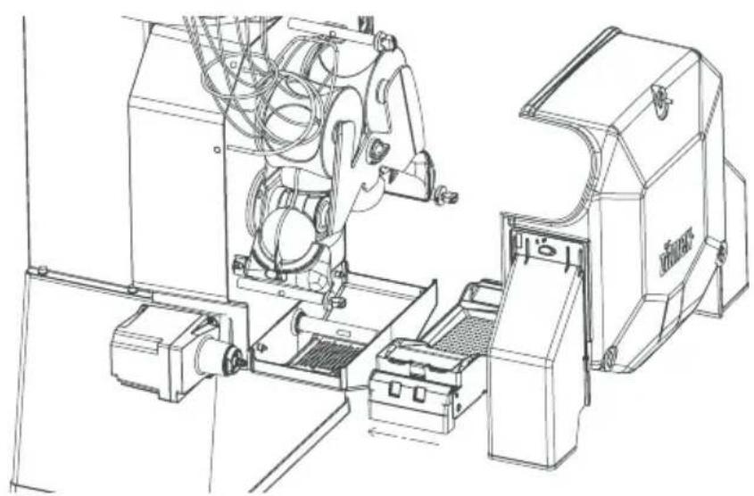
Fig. 20.2+
1
natural_image
Technical line drawing of an industrial machine with hoses and control panel (no text or symbols)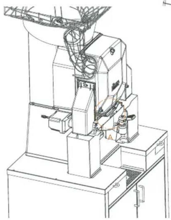
natural_image
Technical line drawing of a mechanical device with no visible text or symbols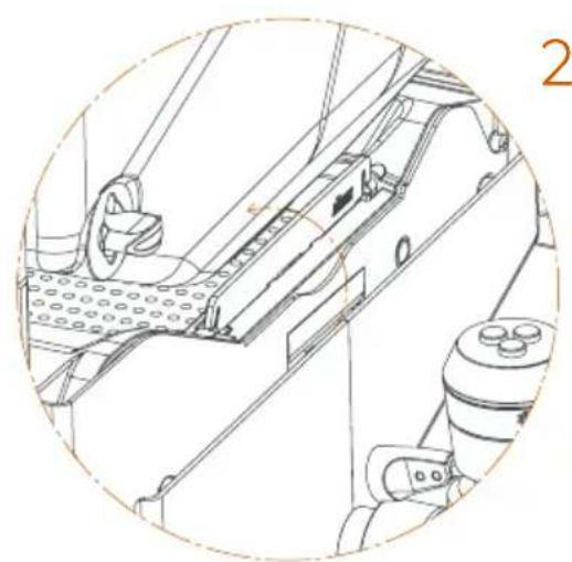
natural_image
Technical line drawing of a mechanical assembly with no visible text or symbolsA
Fig. 20.3+
1
natural_image
Technical line drawing of a mechanical assembly with no visible text or symbols2
natural_image
Technical line drawing of a mechanical device with an inset close-up showing internal components (no text or symbols)Fig. 21
1
natural_image
Technical line drawing of a mechanical device with no visible text or symbols2
natural_image
Technical line drawing of a mechanical device with no visible text or symbols3
natural_image
Technical line drawing of a mechanical component with a highlighted circular detail (no text or symbols)ZUMEX PRESENTS
The fastest and most robust range of machines just got bigger
Speed Up and Speed S +plus have been specially designed for times when a large quantity of juice is needed. The new models are better than ever before in terms of efficiency. They are perfect for restaurants, cafeterias and supermarkets.
Here we will discover how the machine works and how easy they are to clean.
This manual is for the Speed Up and Speed S +plus models.

Register your product here
Speed
User Manual. First steps.
In this manual, you will find everything you need to assemble and start up your Speed Up or Speed S +plus series juicier, as well as information about how it works, its features and accessories as well as some tips and precautions.
Please read the instructions carefully to get the best performance out of your machine.
CONTENTS
3
38
42
43
[Non-Text]
[Non-Text]
[Non-Text]
[Non-Text]
[Non-Text]
[Non-Text]
[Non-Text]
72
22
Zume
contained in this manual without prior notice.
ANNEX
IMPORTANT GENERAL INFORMATION
TECHNICAL FEATURES
43 INSTRUCTIONS FOR USE
PREPARATION
46 UNPACKING AND START-UP
ASSEMBLY AND DETACHMENT OF COMPONENTS ACCORDING TO MODEL
GENERAL OPERATION
CONFIGURATION
CLEANING
ACCESSORIES
TROUBLESHOOTING AND TIPS
EU DECLARATION OF CONFORMITY
Zumex reserves the right to modify the information
contained in this manual without prior notice.
Important general information
This manual refers to the following
Zumex models
| Speed Up models | Zumex Speed Up |
| Zumex Speed Up All-in-One Wide Black | |
| Zumex Speed Up All-in-One Narrow Black | |
| Zumex Speed Up All-in-One Wide Mirror | |
| Zumex Speed Up All-in-One Narrow Mirror | |
| Speed S +plus models | Zumex Speed S +plus |
| Zumex Speed S +plus All-in-One Wide Black | |
| Zumex Speed S +plus All-in-One Narrow Black | |
| Zumex Speed S +plus All-in-One Wide Mirror | |
| Zumex Speed S +plus All-in-One Narrow Mirror | |
| Zumex Speed S +plus Tank All-in-One |
Before you start, we recommend you to take the following precautions into account:
- The specific details about your Zumex juicer (voltage, frequency and other data of interest), can be found on the Identification Label attached to the actual machine.
- Remember that if you have any technical queries, you should get in touch with your Regular Dealer / Official Technical Support Service, always stating the Serial Number on the machine Identification Label.
- Zumex adopts the necessary measures to ensure that the machines placed on the market are selectively collected and managed in an environmentally respectful manner. Please contact your authorised Zumex dealer to correctly dispose of these machines.
- Do not manipulate the machine in such a way that it works without safety elements.
- This appliance can be used by children over the age of 8 or older, or by people with impaired physical, sensorial or mental capacities or who lack experience or knowledge, if they are supervised or have received adequate training with respect to the safe operation of the appliance and they understand the risks entailed.
- Children should be supervised to make sure they do not play with the appliance.
- The cleaning and maintenance to be performed by the user must not be carried out by children without supervision.
- This machine contains an equipotential terminal on the rear to connect the Earth Tap of other appliances to the Earth Tap of your installation through this terminal. If you use it, slacken the nuts and
washers, couple the Earth Tap cable of the auxiliary appliance and firmly tighten the nuts and washers again. This equipotentiality point is indicated with the following symbol:

- Do not spray the appliance with water to clean it.
- This machine is designed for squeezing citrus fruit of the size indicated in this manual: Orange, Limes, Mandarin and Grapefruit.
- Do not use other different fruit to that specified in the manual.
- When you clean, perform maintenance or replace parts, make sure that you have always unplugged the power cable from the socket and it is visible.
- Use the cutting elements with great care, to avoid possible cuts.
- The parts that are in contact with food must be cleaned according to the instructions that you can read in the cleaning chapter.
- If the power cable is damaged, it must be replaced with a cable or special unit to be supplied by the manufacturer or by the after-sales service.
- The unit is manufactured/prepared with a cable's protector in order to prevent accidentally pulling the cable out. Please make sure this protection is placed as indicated below in the instructions,
to guarantee the safety of the appliance.
The instructions may be updated. You can consult the updated instructions on our website www.zumex.com, in the section of the selected model.
If you have any suggestions or comments that you believe may improve our machines or service network, please get in touch with Zumex directly at the address below:

ZUMEX GROUP, S.A.
Polígono Ind. Moncada III C/Molí 2. 46113 Moncada. Valencia. Spain.
Tel. +34 961 301 251 · Fax: +34 961 301 255
zumex@zumex.com / www.zumex.com
ZUMEX SERVICE
Tel. +34 960 800 999 · service@zumex.com
Technical features
| Model | Weight | Dimensions | Width x Height x Depht | | ||
| Speed Up | 76.7 Kg | 169.2 lb | 593 × 624 × 1050 mm | 23.3" x 24.6" x 41.3" |
| Speed Up All-in-One Wide Black | 133 Kg | 293.3 lb | 810 × 682 × 1775 mm | 31.9" x 26.8" x 69.9" |
| Speed Up All-in-One Narrow Black | 129.1 Kg | 284.7 lb | 710 × 682 × 1775 mm | 28" x 26.8" x 69.9" |
| Speed Up All-in-One Wide Mirror | 122.1 Kg | 269.3 lb | 805 x709 × 1774 mm | 31.7" x 27.9" x 69.8" |
| Speed Up All-in-One Narrow Mirror | 113.3 Kg | 249.8 lb | 700 x709 × 1774 mm | 27.5" x 27.9" x 69.8" |
| Speed S +plus | 83.5 Kg | 184.1 lb | 593 × 665 × 1050 mm | 23.3" x 26.2" x 41.3" |
| Speed S +plus All-in-One Wide Black | 131.5 Kg | 290 lb | 810 × 682 × 1775 mm | 31.9" x 26.8" x 69.9" |
| Speed S +plus All-in-One Narrow Black | 127.6 Kg | 281.4 lb | 710 × 682 × 1775 mm | 28" x 26.8" x 69.9" |
| Speed S +plus All-in-One Wide Mirror | 120.6 Kg | 266 lb | 805 x709 × 1774 mm | 31.7" x 27.9" x 69.8" |
| Speed S +plus All-in-One Narrow Mirror | 111.8 Kg | 246.5 lb | 700 x709 × 1774 mm | 27.5" x 27.9" x 69.8" |
| Speed S +plus Tank All-in-One | 110.1 Kg | 242.8 lb | 675 x699 × 1755 mm | 26.6" x 26.3" x 69.1" |
OTHER CHARACTERISTICS (For all models)
| Voltage 100 V | 50-60 Hz 120 V | 60 Hz 220-240 V | 50-60Hz | |||
| Power | 350 W (560 W Cooler) | 320 W (560 W Cooler) | 460 W (560 W Cooler) |
| Consumption | 3.5 A (4.87 A Cooler) | 2.7 A (4.87 A Cooler) | 2 A (2.4 A Cooler) |
| Oranges per minute 36/43 40 37/40 | |||
| Fruits* | Oranges, tangerines, limes, grapefruits | ||
| Size of fruit | 65-81 mm (45-67 mm with Kit S) | ||
| Feeder capacity | 20 kg / 44 lb | ||
| Protection | IPX4 | ||
| Sound pressure level | Lower 70 dB(A) | ||
* For other fruits squeezed always check with your nearest dealer.
Instructions for use
Preparation
To start to extract juice, you must follow the steps below:
1 Unpack your juicer and place it on as flat a surface as possible.
② Make sure that the mains voltage coincides with the voltage indicated on the machine identification label that you will find on the machine.
3 Ensure that no obstacles hinder you during the unpacking process.
Before first use, we recommend that you clean the juicing system.
Please see the section entitled 'Cleaning'.
Unpacking and start-up
Follow the instructions given, depending on the machine model you have purchased. The following components could be loose and if so must be installed properly:
Speed Up
Right cover side outlet (2), Left cover side outlet (3), Power cable (15), Protector cable (16), SS Juice container (40), SS Sub-filter (41), Automatic PulpOut System (42+), SS Tap Up (44U).
See Figures 1 and 3U.
Speed Up All-in-One
Right cover side outlet (2), Left cover side outlet (3), Power cable (15), Protector cable (16), SS Juice container (40), SS Sub-filter (41), Automatic PulpOut System (42+), SS Tap Up (44U).
See Figures 1 and 4U. See section Podium Wide and Podium Narrow (90) for information about your machine stand.
Speed S +plus
Right cover side outlet (2), Left cover side outlet S +plus (3+), Power cable (15), Protector cable (16), Peel bucket (33), Drip tray (34), SS juice container (40), SS Sub-filter (41), Automatic PulpOut System (42+), SS Tap S +plus (44+), Machine supplement (47).
See Figures 1+ and 3+.
Speed S +plus All-in-One
Right cover side outlet (2), Left cover side outlet S +plus (3+), Power cable (15), Protector cable (16), SS Juice container (40), SS Sub-filter (41), Automatic PulpOut System (42+), SS Tap S +plus (44+).
See Figures 1+ and 4+. See section Podium S +plus (90+) for information about your machine stand.
Speed S +plus Tank All-in-One
Right cover side outlet (2), Left cover side outlet S +plus (3+), Power cable (15), Protector cable (16), Automatic PulpOut System (42+), Tank juice container (50), Tank sub-filter (51), Tank/Cooler buoy (52), Tank (53), Shaker (54), Tank Tap (55).
See Figures 1+ and 5+. See section Podium Speed S +plus Tank All-in-One (90) for information about your machine stand.
Drain&Clean System (80)
If you have a Podium model, your machine is equipped with the Drain&Clean system. This system facilitates cleaning and waste disposal by working as a drainage system from the feeder to the waste bin. Thus the machine it self will clean and remove waste automatically.
See Figures 7.1 and 7.2.
Podium Tank S ^+plus All-in-One (90), Podium Black All-in-One (90+), Podium Mirror All-in-One (90+), Podium Cooler (100)
All the stand components can be found inside the stand.
Assembly and detachment of components according to model
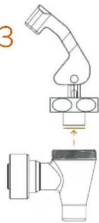
Right cover side outlet (2), Left cover side outlet (3), Left cover side outlet S ^+ plus (3+)
The side outlets are not the same. Ensure that the correct side outlet is installed on the corresponding side.
Assembly of the outlets (Fig. 10).
Line up the bottom of the side outlet and lift up the upper part, ensuring that it closes with a 90^ turn of the knob.
Mount the right outlet by turning the latch clockwise.
Mount the left outlet by turning the latch counter-clockwise.
! Important! There are icons on the part indicating the direction of the turn, do not force the tab in the opposite direction.
Ensure that the side outlets are fully installed and correctly positioned in their place.
Disassembly of the outlets (Fig. 10)
Remove the right outlet by turning the latch counter-clockwise to its vertical position.
Remove the left outlet by turning the latch clockwise to its vertical position.
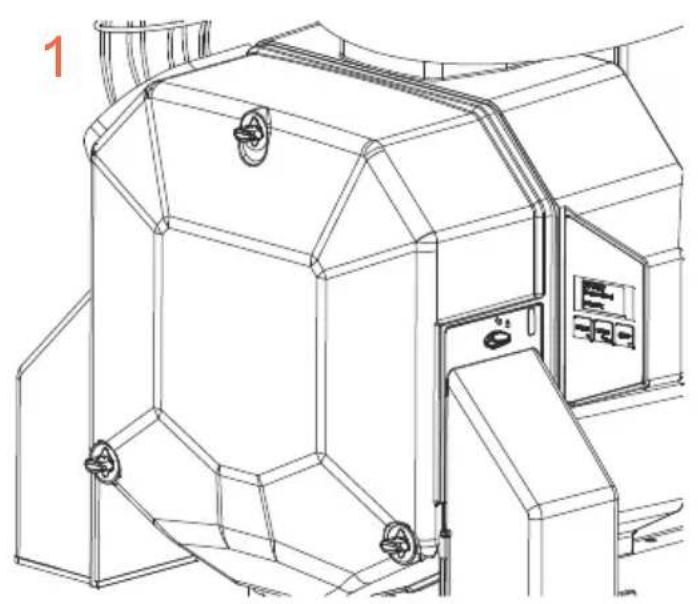
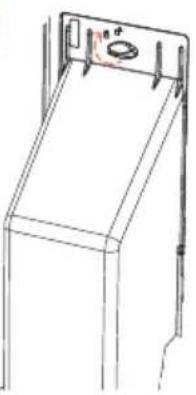
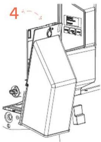
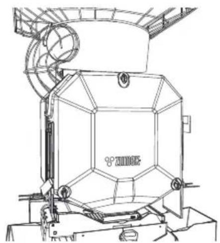
Cover (1)
Assembly of the cover (Fig. 10.1)
Check that the knobs on the shafts of the machine are turned perpendicular to the floor (open)
Hold the cover by the outlet holes, match the holes with the knobs and press until they are completely inserted. Turn the knobs 90° degrees clockwise to secure the cover.
Important! Avoid forcing the cover onto the machine if the shafts are not completely aligned, as this may damage the part.
Disassembly of the cover (Fig. 10.1)
Turn the knobs 90^ degrees until they align with the holes in the cover.
Remove the cover with a horizontal movement, holding it with both hands by the outlet holes.
Important! Avoid forcefully removing the cover if the shafts are not completely aligned, as this may damage the part.
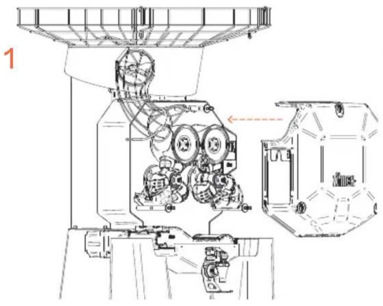
Lower pressing unit (4), Upper pressing unit (5)
Place the pressing units in the shafts (Fig. 1).
If you have a Speed S + plus then refer to the section 1Step kit (19+). Always mount the lower and upper pressing units of the same side at the same time to make it easier to position them.
Injection Plastic Securing Knob (6)
Screw in the knobs to secure the pressing units and the feeder plate (Fig. 1).
If you have a Speed S + plus then refer to the section 1Step kit (19+).
Left peel ejector (7), Right peel ejector (8)
Assembly of the ejector (Fig. 21).
Place the ejectors on the corresponding side and insert them onto the knobs. Push the ejector until the blade is fully inserted into the lower pressing unit and the channel makes contact with the second knob.
Important! If the ejector is not correctly installed as indicated above, the part may be damaged when the machine is in operation.
If you have purchased the Speed S +plus model, read the 1Step Kit (19+) section.
Disassembly of the ejector (Fig. 21)
Pull the ejector out until it is completely free from the machine.
Important! Remove the ejectors before removing other parts of the juicing unit.
Blade holder (9)
Place the blade carefully on its guide and push inwards (Fig. 1).
Blade holder S +plus (9+)
Place the blade carefully on its guide and push inwards (Fig. 1+).
Note: Always insert before inserting the 1Step kit.
Feeder basket (13)
The feeder basket can be removed and re-attached facing guides and making a slight movement until it stops (Fig. 1).
The feeder basket has an easy-to-open door to make it easier to fill the basket up with oranges (Fig. 1).
Power cable (15)
Check cord is plugged in the machine and protected with cord retainer (Fig. 1).
Protector cable with 3 screws (16)
Check protector holds cable with three screws (Fig. 1).
Self Service/Tank Tray gasket 6.3 × 3.5 (17)
If required, this gasket can easily be removed for cleaning and fitted back in by hand (Fig. 1).
Tray bolt (18)
This component only has to be handled if a spare SS Juice container (40) or Tank juice container (50) is requested (Fig. 1). After inserting the spare container, adjust the bolt from the rear to adjust the container position.
1Step kit (19+)
This device allows for easy insertion and removal of the pressing units and peel ejectors in just one step (Fig. 1+).
Before installation remember to insert the Blade holder S +plus (9+).
To install, line up the pressing units with the shafts and adjust their position while sliding them in. Use the central knob to attach the device to the machine.
Note: To remove simply reverse the process.
Assembly of the 1Step Kit (19+)
a) Place the rear holder (19.2+) on a surface. The metal ejector holders should be face down.
b) Match up the lower and upper pressing units (4 and 5). Line up the circular bases of the pressing units with the holes on the holder. Note that the faces of the pressing units are different.
Ensure to mount them as shown in the figure.
d) Line up the protruding cones of the pressing units with the four circular bushes on the front holder (19.1+).
e) Join both holders with the plastic securing knob (6).
c) Turn the 1step kit 180^ and line up the ejectors (7 and 8) with the ejector holders, inserting the extractor blade into the seal of the lower pressing unit. Ensure that both holders are inside the ejector channel as shown in image 4.
Disassembly of the 1Step Kit (19+)
c) From the position shown in image 4, pull the ejectors (7 and 8) sideways to remove them from the metal holders.
a) Turn the kit 180° and unscrew the plastic securing knob (6), which is located behind the pressing units and holds both metal holders (19.1+ and 19.2+).
b) Carefully pull the front holder (19.1+).
c) Separate the lower pressing unit (4) and the upper pressing unit (5).
Note: To clean the unit, refer to the Cleaning section.
Plastic Juice Container (30)
Make sure that the sealing gasket is correctly mounted on the container (Fig. 11). Then place the container in the machine. Line up and place under the container on the four lugs that you will see on the machine (Fig. 2).
Plastic inner filter (31)
Place on the inside of the juice container (Fig. 2).
Plastic juicer filter (32)
Place on the inside of the juice container (Fig. 2).
Peel bucket (33)
Place the peel buckets under the cover side outlets (Fig. 2 or 3U depending on model).
Drip tray (34)
Place under the juice outlet (Fig. 2 or 3U depending on model).
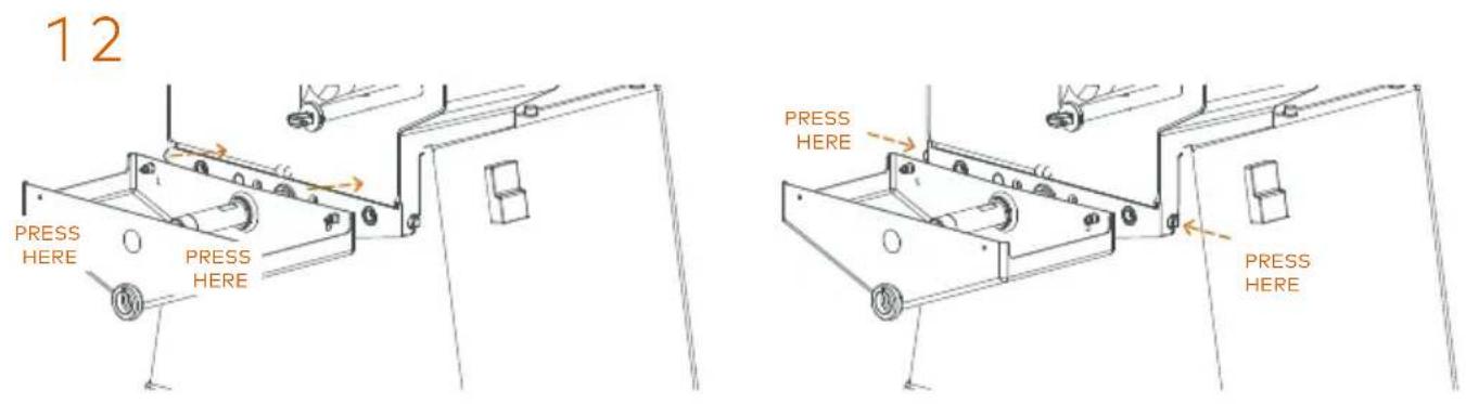
Self Service Juice container (40)
Assembly (Fig. 12).
Line up the tap detector tube (45) with the hole in the back of the container. Slide it until the container fixing pins are fully inserted in the latch holes. Press firmly with your right hand on the front of the container until you hear the click of the latch and then with your left hand until you hear the click of the left latch. Ensure that it is correctly attached by gently pulling on it.
Important! The incorrect assembly of the container can lead to breaks in the seal and small juice leaks. Always make sure that it is correctly fixed to the body of the machine and that the container is in good condition.
Note: To ensure the correct fit of the container, it is recommended to keep the fixing latches clean of juice and/or dirt. Spray a detergent (Zumex Citric Active) in the container fixing holes and the inner part as shown in picture 3. (Fig. 12). Allow the detergent to work for 1 minute. Repeatedly activate the latches and wipe away any remaining product with a clean cloth.
Disassembly (Fig. 12).
To disassemble the container, press the left and right latches at the same time. Slide the container out.
Self Service Sub-filter (41)
Place on the inside of the juice extraction container (Fig. 3U).
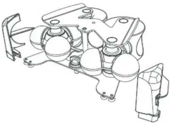
Automatic PulpOut System (42+)
With this device pulp and seeds will be removed automatically during the juicing process.
Assembly (Fig. 20.1+ and 20.2+)
a) Place the rollers (42.1+) into the conveyor belt (42.2+).
b) First place the left hand roller into the metal socket on the frame. Then stretch the belt and place the other roller into the right hand sockets.(Fig. 20.1+).
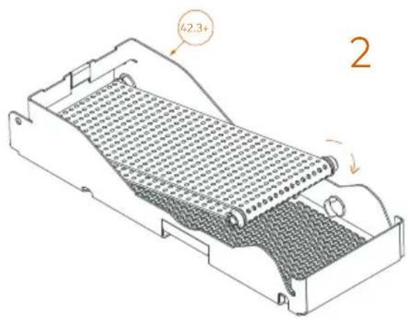
c) Insert the ribbon cover (42.4+) by first of all guiding the right hand side pivots into the slots on the frame (42.3+)(Fig. 20.1+). Then rotate the cover until it rests completely on the frame in a horizontal position and press down until it clips into place.
d) Press down lightly on the sides of the Side Cover (42.5+) and fit it into the holes on the left hand side of the Frame (Fig. 20.1+). Ensure that the pivots have been inserted completely, and that the cover can rotate freely. Leave it in the vertical position.
e) Fit the PulpOut System (42+) into the machine (Fig. 20.2+ and 20.3+). To do this, fit the left roller onto the drive shaft on the left side of the machine. Make sure that the assembly rests and is inserted into the pivots of the container.
f) Turn the Anti-Splash Cap (42.6+) is in a vertical position. It is possible to remove the PulpOut System without removing the cover.
Note: The anti-splash cap must be in a horizontal position to assemble the cover.
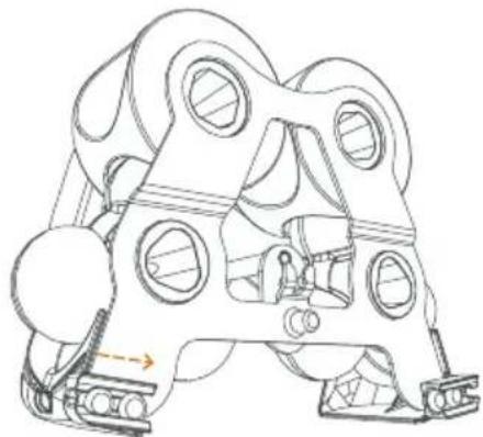
Disassembly (Fig. 20.3+)
To remove the PulpOut from the machine, pull it up and out. To disassemble the unit, reverse the steps indicated for its assembly.
See the Cleaning section for the correct maintenance of the Automatic PulpOut System.
See how it is fitted in various models:
Speed S +plus (Fig. 3+).
Speed S + plus All-in-One (Fig. 4+).
Speed S + plus Tank All-in-One (Fig. 5+).
Self Service Tap Up (44U), Self Service Tap S+plus (44+)
Assembly of the Up Tap (13.1)
Hold the centring device/bottle holder with one hand while turning the nut on the holder with the other hand to secure it to the spout on the container.
Align the tap with the centring device/bottle holder and insert the button between the arms of the holder. Hold the tap with one hand while turning the tap fixing nut with the other hand.
Disassembly of the Up Tap (13.1)
Hold the tap with one hand while loosening the tap fixing nut with the other hand. After loosening the tap fixing nut, gently pull the tap out.
Hold the bottle holder with one hand while unscrewing the centring device/bottle holder nut with the other hand. Pull gently to separate it from the thread of the container.
! Important! Use both hands to dismantle the tap and holder to avoid any parts being dropped or injury.
Assembly of the S+ Tap (14.1+)
To install the S+plus tap in the container, hold the tap with both hands, line up the pin with the hole in the container thread and gently push the tap in. Hold the tap firmly by the bottle holder with one hand and tighten the tap floating fixing nut with the other hand.
Note: Remember to tighten the floating nut until the threads on the container are no longer visible.
If it is not positioned correctly, the tap sensor will not be activated.
Disassembly of the S+ Tap (14.1+)
Hold the tap with one hand while loosening the tap fixing nut with the other hand.
After loosening the tap fixing nut, gently pull the tap out.
! Important! Handle the tap with both hands, do not force the pin or the tap thread. Do not put any weight on the tap.
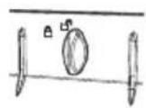
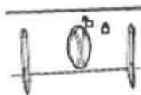
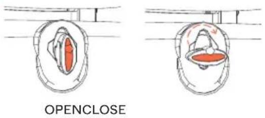
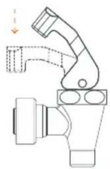
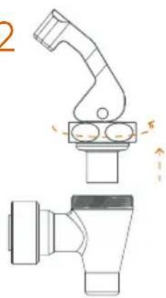
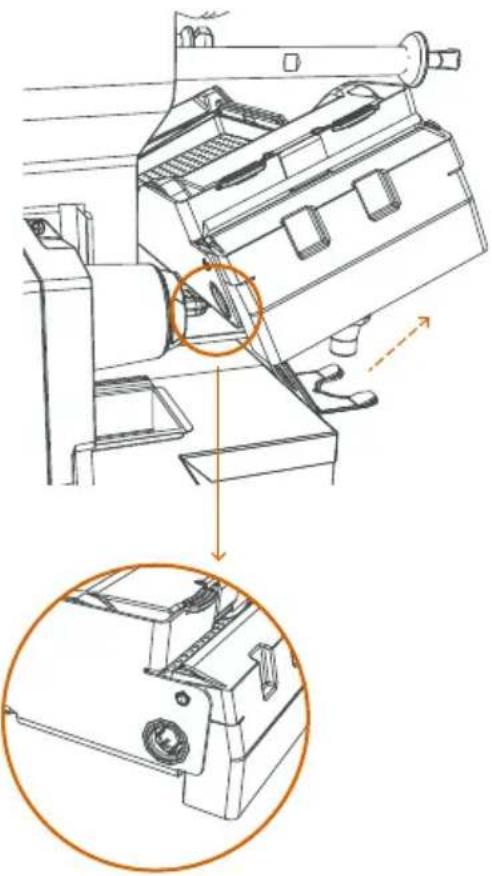
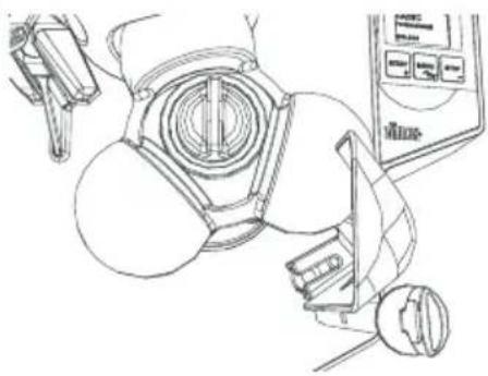
Tap operation (Fig. 13.2 and 14.2+)
The tap is operated by pressing and releasing for juice extraction.
On the SS S +plus tap (44+), the button is located on the outside. The button can be locked in the "free spout" position. To do this, turn the ring with the dotted/continuous lines until the continuous line is over the glass icon. Release the button. It is now locked in position. To release, simply press the button again.
The Speed S +plus All-in-One machine has a bottle holder that can be removed, if necessary, by removing the two rear screws.
On the SS Up tap (44U), the button is located on the inside. The button can be locked in the "free spout" position. To do this, press the button completely and move the metal tab on the side of the bottle holder/centring device. Release the button. It is now locked in position. To release, simply press the button again.
For the daily cleaning of both taps you must remove the upper part as shown in the images (Fig. 13.2 y 14.2+). The Up tap is dismantled by turning the plastic ring on the tap body and then removing the button. The S +plus tap is dismantled by turning the ring on the metal body.
Detector tube gasket (46)
If required, this gasket can be removed for cleaning (Fig. 3U or 4).
Machine supplement (47)
Use this supplement to raise the machine (Fig. 3U or 3+).
Important! Never place the machine onto the supplement alone, it should always be done by at least two people.
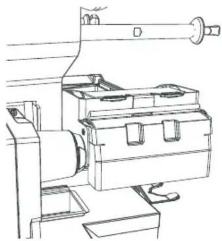
Tank Juice Container (50)
Line up the two side lugs at the ends of the container and press. Pressing the side buttons may help mount it (Fig. 15).
To remove the container, just press the side buttons and pull out towards you.
Tank Sub-filter (51)
Place on the inside of the juice extraction container (Fig. 5+).
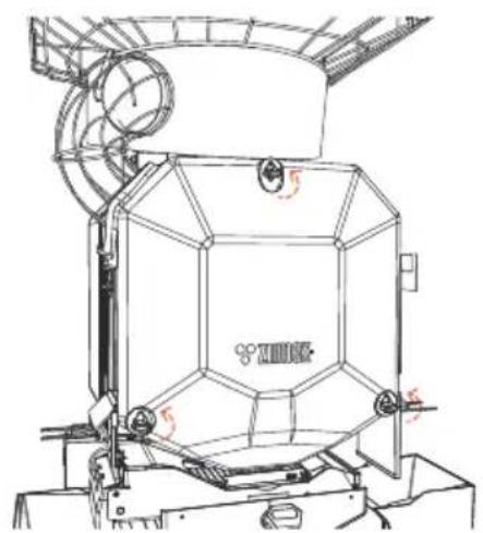
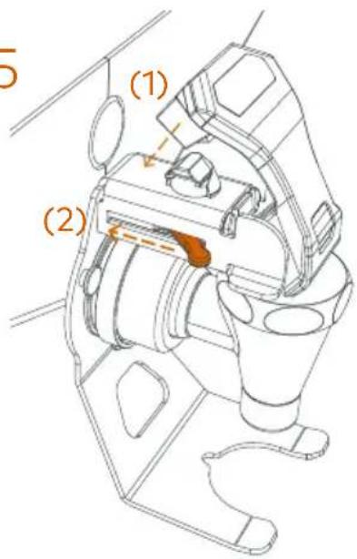
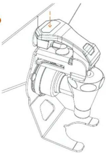
Tank/Cooler Buoy (52)
Tank Model
a) If the support with buoy is loose, loosen the knobs on the support (Fig. 16 (1)).
b) Line up the lugs on the support with the inside of the lid (Fig. 16 (2)).
c) Tighten the knobs (Fig. 16 (2 and 3U)).
d) If a deep clean is necessary, remove the reverse the order of the previous steps and remove the shaft (Fig. 16 (4)).
Cooler or Tank model
Slacken the upper lugs. Line up the plate with the openings from below. Tighten the upper lugs again (Fig. 18).
Tank (53)
Use the thread to secure the Self Service tap to the Tank container (Fig. 5+).
Tank Tap (55)
Use the thread to secure the Self Service Tap to the Tank container. Make sure that it is in upright position (Fig. 17.1).
The Tank Tap can work continuously or discontinuously. Just turn the handle 180^ and it will be locked when the handle is lowered, thus permitting free spout.
For cleaning, you can remove the upper part of the Self Service Tap (Fig. 17.2).
Level detector (56)
This component only needs to be manipulated if a spare part is requested. Remember to place the detector in the same position as the original detector. If you have a Tank machine, the detector is located in the upper part; if you have a Cooler machine, it is located in the lower part (Fig. 5+ y 6).
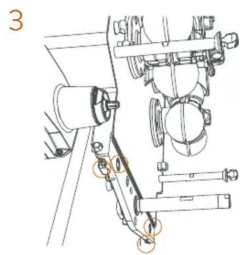
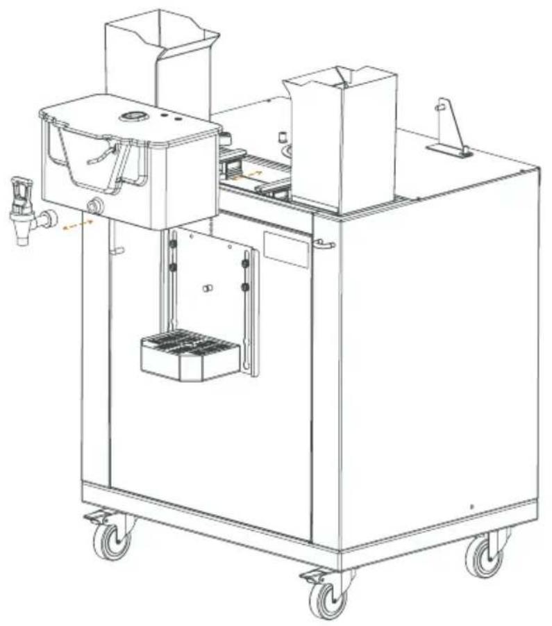
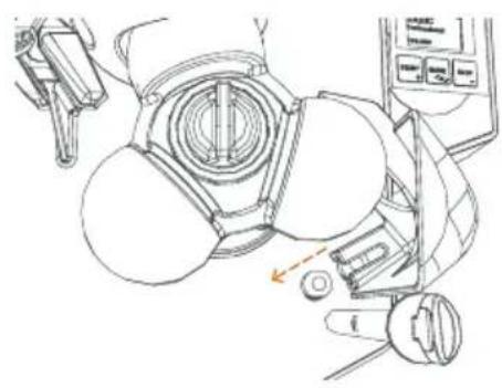
Cooler unit (70)
Place the cooler unit in its housing in the stand (Fig. 6).
Mount the components as indicated in Fig. 18 in this order.
a) Mount the piston-gasket and the lever in the tank following the steps indicated in the enclosed drawing.
b) Fit the tank.
c) Adjust the pump lid inside the tank with the arrow pointing towards you.
d) Secure the metal coupler plate, securing the tank with it.
Podium Tank S ^+plus All-in-One (90), Podium Black All-in-One (90+),
Podium Mirror All-in-One (90+), Podium Cooler (100)
Machine placement on display stand:
Important! This operation must be carried out by 2 or 3 people. It must never be attempted by just one person.
Lock the front wheels of the stand with the brake pedal to prevent it from moving during the installation.
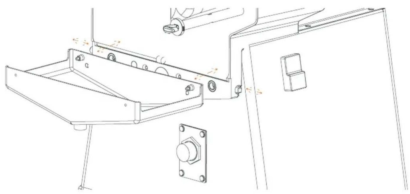
After unpacking the stand, remove the screws from the fixing brackets and put them on one side for later. See detail "A" of Fig. 8.
The peel chutes and the drip tray of the stand with filter are located on the inside of the stand.
Place the machine on the stand, making the inside corners of the machine base coincide with the two rubber blocks of the stand. Thus, the fixing bracket holes will coincide with the machine holes. You can now secure the machine with the screws mentioned above (See Fig. 5+ y 6).
Remember:
The machine and display stand are joined together with the screws supplied, as indicated in this instructions manual.
Never try to tilt the machine or the stand. To move, unlock the wheels.
Individual features for Podium Tank S ^+ plus All-in-One (90)
For the Tank stand, secure the drip tray with its filter in the display stand.
Component 90.7 varies depending on the stand model purchased:
Self Service stand: Component SS stand filter (90.7A).
Tank stand: Component TANK tank guides (90.7B).
The position of components Tray front (90.8) and Tray filter (90.9), can be adjusted to be able to adapt them to different bottle and glass formats.
Individual features for Podium Black and Mirror All-in-One (90+)
The (90+) Podium SS S +plus has two independent waste bins.
Remember to insert both of them every time.
Individual features for Podium Cooler (100)
See Fig. 6 and 9.1 on how to fit the components correctly.
Pass the power cable of the Cooler unit through the hole on the rear door. To do this, you can unscrew the door if necessary (Fig. 9.2).
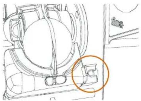
Drain&Clean System Installation
! Important! Unplug the machine from the wall socket.
Podium Tank All-in-One (90)
If fitted, remove the Peel chute (90.6), the SS stand filter (90.7A) and the Stand hopper (90.3) (Fig. 8). Open the front door. If it is connected then remove the Injection securing knob (6), and the Podium Tank Lid (80.5).
Find the upper hole (Fig. 7.2) and insert your hand, taking hold of the Flexible tube (80.4) and placing it in the hole (Fig. 7.1). Do not pull or hold any other part of the machine.
Later, place the lower cover of the tube with the two securing knobs supplied and fit all the previously removed parts back on (Fig. 7.2).
See parts breakdown on how to fit the components (Fig. 8).
Podium Podium Black and Mirror All-in-One (90+)
Open the front doors and remove the waste bins (Fig. 8.1 and 8.2). If it is connected then remove the Injection securing knob (6), and the Podium Tank Lid (80.5).
Find the upper hole (Fig. 7.2) and insert your hand, taking hold of the Flexible tube (80.4) and placing it in the hole (Fig. 7.1). Do not pull or hold any other part of the machine.
Later, place the lower cover of the tube with the two securing knobs supplied and fit all the previously removed parts back on (Fig. 7.2).
See parts breakdown on how to fit the components (Fig. 8.1 and 8.2).
General operation
Once you have installed the machine correctly and before plugging it into the mains, confirm electrical data coincide with the electricity supply. If everything is correct, plug the machine into the mains.
To switch the machine on, press the green ON button. The LED of the ON/OFF button and the digital display of the machine will light up.
Before operating the machine with oranges, you must calibrate it without load. Enter the Calibration section of the CLIENT MENU, or leave the machine operating without load for approximately 1 minute until it comes to a stop.
To make sure the count is correct, you may have to adjust the Offset parameter after calibrating the machine.
Option 1: It does not count all of the oranges. Reduce the Offset value.
Option 2: It counts too many oranges. Increase the Offset value.
To do so, enter MENU>5.Calibration>2.Offset and adjust the value. Exit the Menu and check the count without load, with 2 or 3 oranges. Repeat the process again until you find the value that allows for a correct machine count.
To avoid possible counting errors, try not to stop the machine with an orange trapped between the upper and lower pressing units.
The orange counter is shown in all the models. (Deviation +-1%)
Remember to put a jug or glass under the juice outlet of your machine.
The machine will not work if any safety element is missing.
If necessary, you can always switch the machine off as follows:
A Release the actuator used. For example, the tap.
B Press the STOP button.
C Press the red OFF button.
ONLY IN EMERGENCIES: Unplug the machine directly from the wall socket.
E If the machine does not detect oranges, it will stop approximately 60" after the last orange has passed through.
Loading the feeder
To load the machine feeder with oranges, you can open the Feeder basket (14) door and partially empty the box of oranges into it. Close the door and finish filling the basket.
Juice extraction unit
Make sure that all the elements that permit cutting the orange, extracting the juice and collecting it are mounted on the machine. To do this, consult the machine model purchased on the diagram indicated in section: Unpacking and start-up. Assembly and detachment of components according to model.
Check the state of the containers and filter to guarantee quality juice.
If you have a machine with 1Step kit (19+) you can remove and replace the 1Step kit in just one step.
Juicing
If you have a machine with:
- Automatic PulpOut System (42+), the pulp and any seeds will be expelled from the left hand side of the machine.
- SS Tap Up (44U), SS Tap S +plus (44+) or Tank tap (55), read the instructions for use of the Self Service tap in section Assembly and detachment of components according to model.
- Automatic filling machine, the machine will stop automatically when it reaches maximum level. Remember to fit the Tank/Cooler buoy (2), following the assembly instructions. You will also have to select filling quantity.
Waste area
Make sure that the elements that collect the orange peel are correctly positioned.
Check if the tanks are getting full, to prevent the peel from flowing over.
You can also use the new function, Waste Limit, which enables you to programme an alarm so that the machine will stop when the waste bin is full.
You can select the number of oranges you want to squeeze before the alarm sounds. Once you have squeezed the amount of oranges programmed, the machine will stop and a warning will appear on the display so that the operator knows the waste bin has to be emptied.
If you have purchased a machine with Podium, the peel will fall directly into the Peel buckets
To switch the alarm off, press the OK button for approximately 2" until it comes to a stop.
Remember!
"Short OK", it doesn't switch off.
"Long OK", double "beep", to switch off.
To switch the alarm off permanently, enter the Waste Limit section of the CLIENT MENU.
If the machine is turned off or unplugged, the waste alarm will be eliminated and it will start from zero again.
Machine operation
General
The machine can operate in Professional or Automatic mode in all the models. To shift from one mode to another keep the Mode button pressed for a few seconds. Whenever you change from Automatic to Professional, you will be asked to program the number of oranges to be squeezed. If you do not want to change the quantity, just wait a few seconds or quickly press the OK button. If you wish to modify the quantity, press the + - buttons to select the quantity, and then the OK button until the Saved symbol appears.
Speed Up, Speed S +plus
Speed Up All-in-One, Speed S +plus All-in-One
The START button is not active. It is only active in MANUAL mode.
AUTOMATIC MODE
Control from SS Tap Up (44U)/SS Tap S + Plus (44+).
Uninterrupted operation, whilst the tap is pressed.
PROFESSIONAL MODE
Control from tap whilst pressed.
Minimum number of oranges
Maximum number of oranges
Default value

MANUAL MODE (If the tap does not work)
The START button becomes active in Manual mode.
In manual mode, it is still possible in Automatic and Professional mode from the keypad.
"AUTOMATIC" MANUAL
Uninterrupted operation.
Minimum number of oranges
Maximum number of oranges
Default value

The STOP button is always operative.
Tap Self Service Up (44U), Tap Self Service S+plus (44+)
You have purchased a multi-function tap. This enables you to produce juice either discontinuously or continuously without having to press the button.
See the different possibilities in: Assembly of components according to model, SS Tap Up (44U), SS Tap S +plus (44+).
Speed S +plus Tank All-in-One (90), Speed Pro Cooler Podium (100)
Make sure that the Tank (53) or Tank (70.6) is placed as close as possible to the sensor on the base. Make sure that the buoy is placed correctly on the lid and that it moves freely (Fig. 5+ and 6).
If the Tank/Cooler buoy (52) is not in place, the machine will not work (Fig. 16).
AUTOMATIC MODE
When you connect the machine at the start of the day, select the START button for the machine to start up.
1
The machine starts to squeeze until the tank is full and the Level detector (56) does not find the Tank/Cooler buoy (52). The machine will stop then.
2
When the juice level gets low again, the machine will start up again, about 15" after it has not detected the buoy, and so on and so forth, in automatic mode.
3
The full or half full tank symbol will appear unless STOP has been pressed, indicating that although the machine is in automatic mode, it has stopped, waiting for the tank to be emptied, in order to re-start the filling process. When you press STOP, the symbol will disappear as the machine is no longer operating.
4
PROFESSIONAL MODE
The machine will start up when you press START and will stop when the Level detector (56) does not find the Tank/Cooler buoy (52) or reaches the assigned volume. When the level drops, the machine will not start up again until you press START again.
It has 3 different filling volumes, according to your juice needs.
Non stop operation.
1
2
MANUAL MODE (In case the sensor does not work)
If the Level detector (56) does not work, enter the menu and activate the MANUAL MODE. When you do this, you will be able to enjoy all the machine functions without the detector, until this is repaired.
"AUTOMATIC" MANUAL
1
Program the number of oranges to be squeezed. The machine will stop when it reaches the selected value or the STOP button is pressed.
Remember! In manual mode, you must keep a watch over the juice level so that it never flows over, as level function has been annulled.
2
Configuration
Your Zumex Speed juicer enables you to set parameters to your liking.
Use the electronic device to choose and program the operating mode of your machine. With it, you can control attributes and functionalities following the MENUS enclosed.
To enter the MENU press the STOP and MODE buttons for at least 2 seconds and enter the default PIN (0000). Then press OK button for at least 2 seconds to confirm the PIN.
After entering the menu, you can set:
LANGUAGE: You have a choice of 23 available languages.
PIN: See or change the current PIN so that nobody else can change the machine parameters.
COUNTER: See total or partial counter of the machine. Reset the partial counter, visible on the main screen. To reset the machine counter, press STOP + START for 3 seconds until the counter indicates 0000000.
Ascending or descending CREDIT: You can program the machine credit so the machine can be stopped, in ascending order or descending order, until the machine has been programmed again.
MODE LOCKING SYSTEM: You can get the machine to only work in Automatic or Professional and even so the number of oranges or volume to be squeezed cannot be changed, so that it only squeezes the quantity set by you.
MANUAL MODE (Help mode): Some machine models have an actuator or an auxiliary operating sensor. This can be annulled by selecting the MANUAL mode. [Self Service Model: SS Tap Up (44U), SS Tap S +plus (44+) and Cooler Model: Level detector (56)].
WASTE LIMIT: You can activate an alarm so that the machine will stop when the desired number of oranges has been squeezed. Thus, you will know when the waste bin has to be emptied.
PULPOUT SYSTEM: You can activate the Automatic PulpOut System for automatic pulp and seed removal. You can choose between continuous and non-continuous modes.
Continuous mode, eliminates pulp whenever the machine is juicing. It means the system runs automatically and therefore means that you can go longer between cleans.
Non-continuous mode, means a longer amount of time for the pulp to be filtered. You can choose how often the system is activated depending on the type of fruit used and the quantity of pulp created. Fast frequency will mean that the system is activated more often.
The conveyor belt will run on the following settings:
What is more, you can activate the “Self cleaning” option which means that the belt will be cleaned automatically after the last juicing. In non-continuous mode the “Self cleaning” function will activate 30 seconds after the last use.
On your Display Digital, you will see symbols such as these:

10 oranges15 oranges20 oranges
What is more, you can activate the “Self cleaning” option which means that the belt will be cleaned automatically after the last juicing. In non-continuous mode the “Self cleaning” function will activate 30 seconds after the last use.
On your Display Digital, you will see symbols such as these:

Continuous Mode

Non-continuous Mode Intermediate

Continuous Mode with "Self Cleaning"

Non-continuous mode, high speed with "Self Cleaning"
The PulpOut system can always be stopped by pressing the STOP button. In continuous mode with “Self Cleaning” the STOP button must be pressed twice, once to stop the machine and the second time to stop the self cleaning.
CALIBRATION: You can calibrate the machine to guarantee that the machine count is correct at all times.
MACHINE STATUS: You have access to the different anomalies that a machine stoppage may have caused.
CONTRAST: You can adjust the brightness level on the display.
Remember! Within the CLIENT MENU mode:
"Press OK" to go down a level.
"Press OK at least 2 seconds" to go up a level.
"Press OK at least 2 seconds" to save data (The save symbol will appear).
To exit CLIENT MENU, you must go up the same number of levels you have gone down.
Menu diagram
Main menu
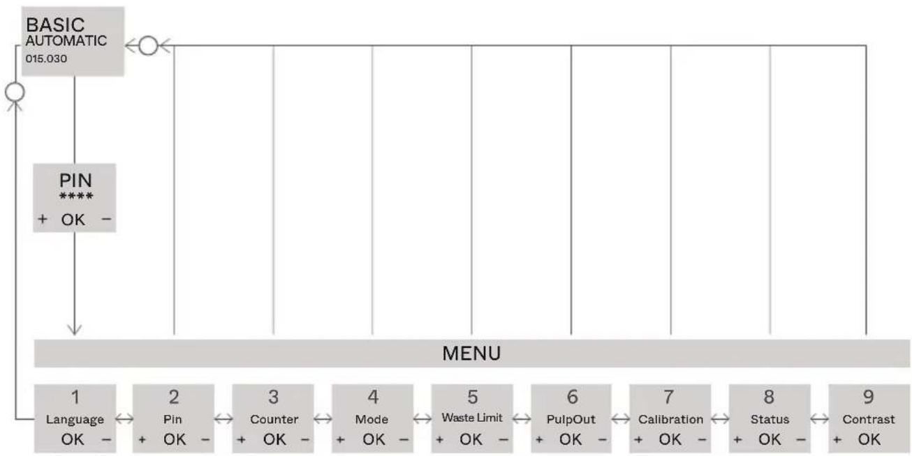
flowchart
graph TD
    A["BASIC AUTOMATIC 015.030"] --> B["PIN **** + OK -"]
    B --> C["MENU"]
    C --> D["1 Language OK -"]
    C --> E["2 Pin + OK -"]
    C --> F["3 Counter + OK -"]
    C --> G["4 Mode + OK -"]
    C --> H["5 Waste Limit + OK -"]
    C --> I["6 PulpOut + OK -"]
    C --> J["7 Calibration + OK -"]
    C --> K["8 Status + OK -"]
    C --> L["9 Contrast + OK"]
| 1 | LANGUAGE. Select the language to operate the machine. | PULPOUT. Choose the mode for the Automatic PulpOut System. |  |
| 2 | PIN. See or change the PIN. | CALIBRATION. To calibrate the machine for correct count. |  |
| 3 | COUNTER. See total or partial counter of the machine. | STATUS. Access the different anomalies that a machine stoppage may have caused. |  |
| 4 | MODE. Select the working mode: automatic or professional. | CONTRAST. To adjust the brightness level on the display. |  |
| 5 | WASTE LIMIT. Activate a warning to know when to empty the waste bin. |
Cleaning
Zumex recommends cleaning the machine at least once or twice a day, depending on how much it is used in order to maintain optimal food hygiene conditions.
Zumex recommends using Zumex Citric Active Detergent™, which is specially designed to clean citrus juicers with a high descaling effect for wax and pulp.
For correct cleaning you must follow the steps below:
A All of the plastic components are dishwasher safe.
B Do not put the SS Tap Up (44U), SS Tap S +plus (44+) in the dishwasher as it can lead to premature oxidation of the stainless steel.
All models
1 Unplug the machine from mains.
2 For assembly and disassembly check the relevant section for each component found in the Assembly and Disassembly section.
3 Remove Side Outlets.
4 Remove the Cover.
5 Follow the instructions for the Assembly/disassembly of the various components dependent on model.
Speed Up, Speed Up All-in-One,
Speed Cooler Podium
6 Remove the blade-holder, pulling towards you from the handle.
! WARNING! Handle this part with great care as you could cut yourself.
7 Extract the peel ejectors from their supports (Fig. 1)
8 Remove the pressing units by pairs, previously unscrewing the securing knobs (Fig. 1).
9 Remove the juice containers and filters; see the respective Figure according to model according to section Unpacking and start-up.
Speed S +plus, Speed S +plus All-in-One, Speed S +plus Tank All-in-One
6 ^+ Remove the 1Step Unit (19+).
There are two possibilities when cleaning:
- Complete cleaning: once the unit has been removed from the machine, get rid of extra pulp and peel if there is any washing it with water and if necessary a mild soap. The whole unit is also dishwasher safe.
- Deep cleaning: all of the components can be removed and can be cleaned individually. Zumex recommend this type of deep cleaning at least once a week depending on how much usage the machine gets.
7 ^+ Remove the Blade holder S +plus (9+) and clean it carefully taking care not to hurt yourself.
8 ^+ Remove the PulpOut System (42+).
9 ^+ To clean all of the components of the unit they should be removed and washed individually, this can be done by hand or in the dishwasher.
Things to remember
C Cleaning non-detachable elements. Use a damp cloth with lukewarm water and soap, and then rinse.
D Remember that although some parts are similar they must be mounted on different sides.
E Transparent parts and dish-washers: these parts can be washed in the dish-washer, although you must make sure you use the correct soap, salt and brightener so that the parts remain shiny and transparent.
F In models with tap: Unscrew the tap from the container, separate the button from the body to clean thoroughly. Remove taps as indicated in the sections: SS Tap Up (44U), SS Tap S +plus (44+), Tank Tap (55) of Assembly and detachment of components according to model.
G In models with the Drain&Clean System, Zumex recommends cleaning the inside of the tube with a large brush (Fig. 7.1) at the start of the feeding tube, at least once a week. This process will avoid any possible blockages.
H Feeding tube: Whether or not your machine has the Drain & Clean System, it is advisable to disassemble the turntable from the feeder for complete removal of wax and debris.
For any area with difficult cleaning Access, we recommend using the brush (Fig. 1) included in the machine.
Accessories
There is a wide range of accessories available for you to make the most of your machine:
1Step Kit
With this accessory you will be able to dismantle the machine in just 10 seconds and clean it under the tap or in the dishwasher.
*Accessory available for all of the Speed S +plus range. Including juice extraction system.
M elbow feeder cover
Impedes access to the fruit inside the M feeder elbow thus preventing contact with external agents.
L elbow feeder cover
Impedes access to the fruit inside the L feeder elbow thus preventing contact with external agents.
Two-position tray
Accessory available for Black podiums for serving juice in glasses and bottles
Closed basket
Accessory that closes off and prevents access to the basket of oranges.
Pulp cover kit
Part covering the sweeper belt that hides the pulp and prevents any possible splashes.
Kit S / 1Step Kit S
To juice fruit that has a diameter of 45 mm to 67 mm.
Kit L / 1Step Kit L
To juice fruit that has a diameter of 75 mm to 95 mm.
DCS System
To juice soft or overripe citrus fruit.
Display Stand
So that you can keep your bottles of freshly squeezed juice ready to take away. Available in two sizes.
Contrabarra Kit
Integrates waste management keeping things practical and clean.
Bottle set
For self-service restaurants - bottles, glasses or jugs of juice can be distributed easily. Includes three trays (4 heights). It is integral to the podium and the whole set can be transported with ease.
Zumex Pack
Fresh drinks can be packaged for commercialization, especially freshly squeezed orange juice. There are 6 formats (1.5 l, 1 l, 75 cl, 50 cl, 33cl and 25 cl) and custom-made stickers.
Check www.zumex.com for more information on accessories for your machine.
Troubleshooting and tips
To eliminate an error, press OK briefly and check that the cause of the fault is corrected, as indicated in the table below.
| ERROR POSSIBLE CAUSE ACTION | ||
| 01 Cover | Does not detect the cover safety device | Check cover placementCheck side outlet placementCheck magnet placementCheck connected cablesCheck cover detector |
| 02 Tray | Does not detect container | Check container placementCheck wiring connectionCheck container detector |
| 03 Motor power | The motor does not work at correct voltage | Check mains voltageCheck electronics plate |
| 04 Halt | Electricity cut | Check mains voltage cableCheck inner connection of cables |
| 05 Overcurrent | The motor has over-consumption | Check obstacles in juice extraction systemCheck fruit hardnessCheck motorCheck cooling |
| 06 No Float | Does not detect buoy | Position buoy correctlyPosition tank correctlyCheck wiringCheck detector |
| 07 Credit | Counter limit reached | Eliminate counter limitReprogram counter limit |
| 08 Waste Limit | Counter limit reached | Press "OK" for longer until you hear a double "beep" |

zumex.com
ZUMEX PRESENTA
Grifo Self Service Up (44U), Grifo Self Service S
+plus (44+)
Montaje Grifo Up (13.1)
Boya Tank/Cooler (52)
Modelo Tank
Podium Tank S ^+plus All-in-One (90), Podium Black All-in-One (90+),
Podium Mirror All-in-One (90+), Podium Cooler (100)
Podium Tank All-in-One (90)
Speed Up All-in-One, Speed S +plus All-in-One
Speed S +plus, Speed S +plus All-in-One,
Speed S +plus Tank All-in-One
natural_image
Pure geometric diagram with two diagonal lines crossing inside a square (no text or symbols)
zumex.com
ZUMEX PRESENTE
Speed S +plus All-in-One
Speed S +plus Tank All-in-One
Ensemble Drain&Clean System (80)
Podium Tank S ^+plus All-in-One (90), Podium Black All-in-One (90+),
Podium Mirror All-in-One (90+), Podium Cooler (100)
Joint bac Self Service/Tank 6.3 × 3.5 (17)
Robinet Self Service Up (44U), Robinet Self Service S+plus (44+)
Podium Tank S ^+plus All-in-One (90), Podium Black All-in-One (90+),
Podium Mirror All-in-One (90+), Podium Cooler (100)
Installation Drain&Clean System:
Podium Tank All-in-One (90)
Speed Up All-in-One, Speed S +plus All-in-One
MANUEL "PROFESSIONNEL"
Speed S +plus Tank Podium (90),
MANUEL "PROFESSIONNEL"
Speed S +plus, Speed S +plus All-in-One,
Speed S +plus Tank All-in-One
Speed S +plus All-in-One
Speed S +plus Tank All-in-One
Podium Tank S ^+plus All-in-One (90), Podium Black All-in-One (90+),
Podium Mirror All-in-One (90+), Podium Cooler (100)
Podium Tank S ^+plus All-in-One (90), Podium Black All-in-One (90+), Podium Mirror All-in-One (90+), Podium Cooler (100)
Podium Tank All-in-One (90)
Speed Up All-in-One, Speed S +plus All-in-One
Hahn Self Service Up (44U), Hahn Self Service S +plus (44+)
Speed S +plus, Speed S +plus All-in-One,
Speed S +plus Tank All-in-One
Speed S +plus All-in-One
Speed S +plus Tank All-in-One
Drain&Clean System (80)
Podium Tank S ^+plus All-in-One (90), Podium Black All-in-One (90+),
Podium Mirror All-in-One (90+), Podium Cooler (100)
Podium Tank S ^+ plus All-in-One (90), Podium Black All-in-One (90+), Podium Mirror All-in-One (90+), Podium Cooler (100)
! Podium Tank All-in-One (90)
Speed S + plus Self Service, Speed S + plus All-in-One,
Speed S +plus Tank All-in-One
EU DECLARATION OF CONFORMITY
ZUMEX GROUP S.A., whose registered offices are situated at Polígono Industrial de Moncada III, C/ Molí, 2 – 46113 - Moncada, Valencia (Spain) does hereby declare, under its sole responsibility, that Speed Pro Basic, Speed Pro Cooler Podium, Speed Pro Self-Service, Speed Pro Self-Service Podium, Speed Pro Tank Podium, Speed Up, Speed Up All in One, Speed Up All in One Narrow, Speed S +plus, Speed S +plus All in One, Speed S +plus All in One Narrow, Speed S +plus Tank Podium juicer machines are in compliance with the provisions of the European Directives detailed below:
2006/42/EU Security on machinery
2014/35/EU Electrical equipment designed for use within certain voltage limits
2014/30/EU Electromagnetic compatibility (EMC)
REG.(EC) N° 1935/2004 Materials and articles intended to come into contact with food
REG.(EC) N° 10/2011 Plastic materials and articles intended to come into contact with food
REG.(EC) N° 2023/2006 Good manufacturing practice for materials and articles intended to come into contact with food
2011/65/EU Restriction of the use of certain hazardous substances in electrical and electronic equipment ROHS)
2012/19/EU Waste electrical and electronic equipment (WEEE)
To ensure such conformity, the above-mentioned model complies with the following harmonized standards and/or regulations:
| IEC 60335-1 | 2010 | Safety of household electrical appliances and similar. Part 1: General requirements |
| + A1 | 2013 |
| IEC 60335-2-64 | 2002 | Safety of household and similar electrical appliances. Part 2-64: Particular requirements for commercial electric kitchen machines |
| + A1 | 2007 |
EN 62233 2008 Measurement methods for electromagnetic fields of household appliances and similar apparatus with regard to human exposure
EN 55014-1 2008
+ A1 2009
+A2 2012
Electromagnetic compatibility. Requirements for household appliances,
electric tools and similar apparatus. Part 1: Emission
EN 55014-2 2015 Electromagnetic compatibility. Requirements for household appliances, electric tools and similar apparatus. Part 2: Immunity. Product family standard
EN 61000-3-2 2014 Electromagnetic compatibility (EMC). Part 3-2: Limits. Limits for harmonic current emissions (equipment input current <= 16 A per phase)
EN 61000-3-3 2013 Electromagnetic compatibility (EMC) - Part 3-3: Limits. Limitation of voltage changes, voltage fluctuations and flicker in public low-voltage supply systems, for equipment with rated current <= 16 A per phase and not subject to conditional connection
NSF/ANSI 8 2012 National Sanitation Foundation. Commercial powered food preparation equipment
NSF/ANSI 51 2014 National Sanitation Foundation. Food equipment materials
Moncada, February 06th, 2019


natural_image
Abstract line drawing with intertwined curves and a central vertical line (no text or symbols)Francisco Serrano Operations Manager

bar
| Category | Value | |---|---| | Category 1 | 100 | | Category 2 | 100 | | Category 3 | 100 | | Category 4 | 100 | | Category 5 | 100 | | Category 6 | 100 | | Category 7 | 100 | | Category 8 | 100 | | Category 9 | 100 | | Category 10 | 100 | | Category 11 | 100 | | Category 12 | 100 | | Category 13 | 100 | | Category 14 | 100 | | Category 15 | 100 | | Category 16 | 100 | | Category 17 | 100 | | Category 18 | 100 | | Category 19 | 100 | | Category 20 | 100 | | Category 21 | 100 | | Category 22 | 100 | | Category 23 | 100 | | Category 24 | 100 | | Category 25 | 100 | | Category 26 | 100 | | Category 27 | 100 | | Category 28 | 100 | | Category 29 | 100 | | Category 30 | 100 | | Category 31 | 100 | | Category 32 | 100 | | Category 33 | 100 | | Category 34 | 100 | | Category 35 | 100 | | Category 36 | 100 | | Category 37 | 100 | | Category 38 | 100 | | Category 39 | 100 | | Category 40 | 100 | | Category 41 | 100 | | Category 42 | 100 | | Category 43 | 100 | | Category 44 | 100 | | Category 45 | 100 | | Category 46 | 100 | | Category 47 | 100 | | Category 48 | 100 | | Category 49 | 100 | | Category 50 | 100 | | Category 51 | 100 | | Category 52 | 100 | | Category 53 | 100 | | Category 54 | 100 | | Category 55 | 100 | | Category 56 | 100 | | Category 57 | 100 | | Category 58 | 100 | | Category 59 | 100 | | Category 60 | 100 | | Category 61 | 100 | | Category 62 | 100 | | Category 63 | 100 | | Category 64 | 100 | | Category 65 | 100 | | Category 66 | 100 | | Category 67 | 100 | | Category 68 | 100 | | Category 69 | 100 | | Category 70 | 100 | | Category 71 | 100 | | Category 72 | 100 | | Category 73 | 100 | | Category 74 | 100 | | Category 75 | 100 | | Category 76 | 100 | | Category 77 | 100 | | Category 78 | 100 | | Category 79 | 100 | | Category 80 | 100 | | Category 81 | 100 | | Category 82 | 100 | | Category 83 | 100 | | Category 84 | 100 | | Category 85 | 100 | | Category 86 | 100 | | Category 87 | 100 | | Category 88 | 100 | | Category 89 | 100 | | Category 90 | 100 | | Category 91 | 100 | | Category 92 | 100 | | Category 93 | 100 | | Category 94 | 100 | | Category 95 | 100 | | Category 96 | 100 | | Category 97 | 100 | | Category 98 | 100 | | Category 99 | 100 | | Total (Total) |zumex®
www.zumex.com