GLL2XG Professional - Laser level BOSCH - Free user manual and instructions
Find the device manual for free GLL2XG Professional BOSCH in PDF.

| Product type | Line laser level |
| Brand | Bosch |
| Model | GLL2XG Professional |
| Dimensions (L × W × H) | 87 × 64 × 87 mm |
| Weight (without battery/alkaline cells) | 0.3 kg |
| Power supply | Lithium-ion battery 3.7 V (1.0 Ah) or 2 LR6 (AA) batteries |
| Battery life | 8 h |
| Range | 20 m |
| Leveling accuracy | ±0.6 mm/m |
| Self-leveling range | ±3.5° |
| Leveling time | < 6 s |
| Laser class | 2 |
| Laser type | < 5 mW, 500–540 nm |
| Tripod thread | 1/4" |
| Protection rating | IP55 |
| Operating temperature | -10 °C to +40 °C |
| Main functions | Horizontal and vertical line projection, self-leveling, manual mode |
| Included accessories | USB Type-C® cable, protective cover |
| Maintenance and cleaning | Clean with a soft, damp cloth, no detergents or solvents |
| Safety | Do not look into the laser beam, avoid eye exposure |
| Spare parts and repairability | Repair only by a qualified technician using original Bosch parts |
| General information | Indoor use, compatible with standard tripod |
Frequently Asked Questions - GLL2XG Professional BOSCH
User questions about GLL2XG Professional BOSCH
0 question about this device. Answer the ones you know or ask your own.
Ask a new question about this device
Download the instructions for your Laser level in PDF format for free! Find your manual GLL2XG Professional - BOSCH and take your electronic device back in hand. On this page are published all the documents necessary for the use of your device. GLL2XG Professional by BOSCH.
USER MANUAL GLL2XG Professional BOSCH
natural_image
3D illustration of a Bosch industrial component with internal ports (no text or symbols)en Original instructions
fr Notice originale
es Manual original
Bosch Power Tools 1 609 92A C6K | (21.05.2025)
(14) 1608 M00 05J
natural_image
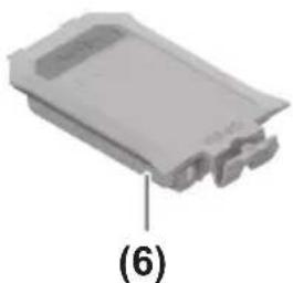
3D model of a gray plastic electronic component with two ports and a label (6) pointing to its interior (no text or symbols on the component itself)1 608 M00 C5D
natural_image
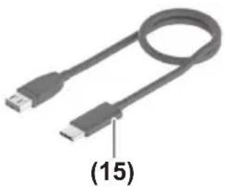
Close-up of a USB cable with a labeled end (15), showing no text or symbols beyond the label.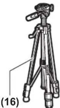
natural_image
Line drawing of a tripod with adjustable legs and a handle, labeled (16) at the base (no text or symbols on the tripod itself)BT 150 0 601 096 B00
natural_image
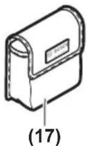
Simple line drawing of a rectangular device with a label and number (17) below it, no readable text or symbols present.English
Safety Instructions

All instructions must be read and observed in order for the measuring tool to function safely. The safeguards integrated into the measuring tool may be compromised if the measuring tool is not used in accordance with these instructions. Never make warning signs on the measuring tool unrecognisable. SAVE THESE IN-STRUCTIONS FOR FUTURE REFERENCE AND INCLUDE THEM WITH THE MEASURING TOOL WHEN TRANSFERRING IT TO A THIRD PARTY.
▶ Warning! If operating or adjustment devices other than those specified here are used or other procedures are carried out, this can lead to dangerous exposure to radiation.
The measuring tool is delivered with a laser warning sign (marked in the illustration of the measuring tool on the graphics page).
▶ If the text of the laser warning label is not in your national language, stick the provided warning label in your national language over it before operating for the first time.
Do not direct the laser beam at persons or animals and do not stare into the direct or reflected laser beam yourself. You could blind somebody, cause accidents or damage your eyes.
▶ If laser radiation hits your eye, you must close your eyes and immediately turn your head away from the beam.
▶ Do not make any modifications to the laser equipment.
▶ Do not use the laser goggles (accessory) as protective goggles. The laser goggles make the laser beam easier to see; they do not protect you against laser radiation.
▶ Do not use the laser goggles (accessory) as sunglasses or while driving. The laser goggles do not provide full UV protection and impair your ability to see colours.
▶ Have the measuring tool repaired only by a qualified specialist using only original replacement parts. This will ensure that the safety of the measuring tool is maintained.
▶ Do not let children use the laser measuring tool unsupervised. They could unintentionally blind themselves or other persons.
▶ Do not use the measuring tool in explosive atmospheres which contain flammable liquids, gases or dust. Sparks may be produced inside the measuring tool, which can ignite dust or fumes.
▶ Do not modify or open the battery. There is a risk of short-circuiting.
In case of damage and improper use of the battery, vapours may be emitted. The battery can set alight or explode. Ensure the area is well ventilated and seek medical attention should you experience any adverse effects. The vapours may irritate the respiratory system.
If used incorrectly or if the battery is damaged, flammable liquid may be ejected from the battery. Contact with this liquid should be avoided. If contact accidentally occurs, rinse off with water. If the liquid comes into contact with your eyes, seek additional medical attention. Liquid ejected from the battery may cause irritation or burns.
The battery can be damaged by pointed objects such as nails or screwdrivers or by force applied externally. An internal short circuit may occur, causing the battery to burn, smoke, explode or overheat.
When the battery is not in use, keep it away from paper clips, coins, keys, nails, screws or other small metal objects that could make a connection from one terminal to another. A short circuit between the battery terminals may cause burns or a fire.
▶ Only use the battery with products from the manufacturer. This is the only way in which you can protect the battery against dangerous overload.


Protect the battery against heat, e.g. against continuous intense sunlight, fire, dirt, water and moisture. There is a risk of explosion and short-circuiting.
Keep the measuring tool and the magnetic accessories away from implants and other medical devices, e.g. pacemakers or insulin pumps. The magnets inside the measuring tool and accessories generate a field that can impair the function of implants and medical devices.
▶ Keep the measuring tool and the magnetic accessories away from magnetic data storage media and magnetically sensitive devices. The effect of the magnets inside the measuring tool and accessories can lead to irreversible data loss.
8 | English
Product Description and Specifications
Please observe the illustrations at the beginning of this operating manual.
Intended Use
The measuring tool is intended for determining and checking horizontal and vertical lines.
The measuring tool is suitable for indoor use.
This product is a consumer laser product in accordance with EN 50689.
Product Features
The numbering of the product features shown refers to the illustration of the measuring tool on the graphic page.
(1) 1/4" tripod mount
(2) Laser beam outlet aperture
(3) On/off switch
(4) Charge indicator of the lithium-ion battery pack ^a)
(5) USB Type-C® port ^a)b)
(6) Lithium-ion battery pack ^4
(7) Lithium-ion battery pack locking mechanism ^a)
(8) Locking mechanism of the battery compartment cover
(9) Battery compartment cover
(10) Laser warning label
(11) Serial number
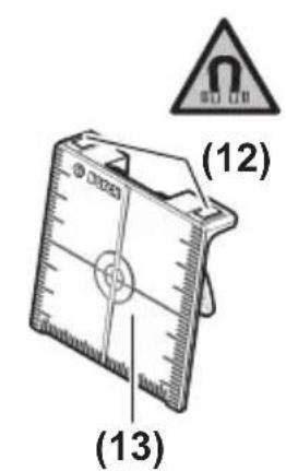
(12) Magnet ^a)
(13) Laser target plate ^a)
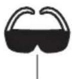
(14) Laser viewing glasses ^a)
(15) USB Type-C ^® cable ^a)
(16) Tripod ^a)
(17) Protective bag ^a)
a) This accessory is not part of the standard scope of delivery.
b) USB Type-C® and USB-C® are trademarks of USB Implementers Forum.
Technical Data
| Line laser GLL2XG | |
| Article number | 3 601 K65 3G. |
| Working rangeA) | 20 m |
| Levelling accuracy B)C) | ±0.6 mm/m |
| Self-levelling range ±3.5° | |
| Levelling time < 6 s | |
| Operating temperature -10 °C to +40 °C | |
| Storage temperature (without rechargeable battery) -20 °C to +70 °C | |
| Max. altitude 2000 m | |
| Relative air humidity max. 90 % | |
| Pollution degree according to IEC 61010-1 2 | D) |
| Laser class 2 | |
| Laser type < 5 mW, 500–540 nm | |
| C6 | 5 |
| Divergence 25 × 5 mrad (full angle) | |
| Tripod mount 1/4" | |
| Energy supply | |
| – Lithium-ion battery pack 3.7 V | |
| – Non-rechargeable batteries (alkaline man-ganese) | 2 × 1.5 V LR6 (AA) |
| Operating time 8 h | |
| WeightE) | 0.3 kg |
| Dimensions (length × width × height) 87 × 64 × 87 mm | |
| Protection rating | IP55 |
| Lithium-ion battery pack (accessory) | BA 3.7V 1.0Ah A |
| Article number | 1 607 A35 ON81 607 A35 17H |
| Charging connection | USB Type-C® |
| Recommended USB Type-C® cable | 1 600 A01 6A8 |
| Rated voltage 3.7 V | — |
10 | English
Line laser GLL2XG
| Capacity 1.0 Ah | |
| Recommended ambient temperature during charging | +10 °C to +35 °C |
| Recommended ambient temperature during operation and during storage | -10 °C to +45 °C |
Power supply
| Output voltage 5.0 V | == |
| Minimum output current 500 mA |
A) The working range may be reduced by unfavourable environmental conditions (e.g. direct sunlight).
B) Valid when levelled (0°)
C) The values stated presuppose normal to favourable environmental conditions (e.g. no vibration, no fog, no smoke, no direct sunlight). Extreme fluctuations in temperature can cause deviations in accuracy.
D) Only non-conductive deposits occur, whereby occasional temporary conductivity caused by condensation is expected.
E) Weight without lithium-ion battery pack/non-rechargeable batteries
The serial number (11) on the type plate is used to clearly identify your measuring tool.
Measuring Tool Power Supply
The measuring tool can be operated either with a Bosch lithium-ion battery pack (6) or with conventional non-rechargeable batteries.
Note: Never store the measuring tool without an inserted battery compartment cover (9) or lithium-ion battery pack (6), particularly in dusty or humid environments.
Operation with Non-Rechargeable Batteries
To switch from a lithium-ion battery pack (6) to non-rechargeable batteries, remove the lithium-ion battery pack (6).
It is recommended that you use alkaline manganese batteries to operate the measuring tool.
Insert the non-rechargeable batteries.
When inserting the batteries, ensure that the polarity is correct according to the illustration on the inside of the battery compartment.
Insert the battery compartment cover (9) and let it click into place.
If the non-rechargeable batteries are running low, the laser lines will flash slowly for approx. 1 min.
If the non-rechargeable batteries are empty, the laser lines will flash quickly for approx. 10 s, then the measuring tool will switch off.
Always replace all the batteries at the same time. Only use batteries from the same manufacturer and which have the same capacity.
▶ Take the batteries out of the measuring tool when you are not using it for a prolonged period of time. The batteries can corrode during prolonged storage in the measuring tool.
Operation with Lithium-Ion Battery Pack
Inserting/Replacing a Lithium-Ion Battery Pack
To switch from non-rechargeable batteries to a lithium-ion battery pack (6), remove the battery compartment cover (9) and the inserted non-rechargeable batteries.
Insert the lithium-ion battery pack (6) and let the locking mechanism (7) click into place.
To remove the lithium-ion battery pack (6), press the locking mechanism (7) and take the lithium-ion battery pack out of the measuring tool.
Charging a Lithium-Ion Battery Pack
For charging, use only a USB power supply unit whose output voltage and minimum output current comply with the requirements in the "Technical data" section. Observe the operating manual of the USB power supply unit.
▶ Pay attention to the mains voltage. The voltage of the power source must match the voltage specified on the type plate of the power supply.
▶ Only use the USB connection to charge the battery at an ambient temperature of between +10 °C and +35 °C. Charging outside of this temperature range can damage the battery and increase the risk of fire.
Note: Lithium-ion rechargeable batteries are supplied partially charged according to international transport regulations. To ensure full rechargeable battery capacity, fully charge the rechargeable battery before using your tool for the first time.
If the lithium-ion battery pack is running low, the laser lines will flash slowly for approx. 1 min.
If the lithium-ion battery pack is empty, the laser lines will flash quickly for approx. 10 s, then the measuring tool will switch off.
Open the flap for the USB Type-C ^® port (5). Connect the USB port to a USB power supply unit using the USB cable (15). Connect the USB power supply unit to the mains supply.
12 | English
Colour of charge indicator (4) Meaning
Yellow Lithium-ion battery pack is being charged.
Green Lithium-ion battery pack is fully charged.
Red Charging voltage or charging current is unsuitable.
Remove the USB cable (15) after completing the charging process. Close the flap for the USB Type-C® port (5) to protect it from dust and splashes.
Operation
Starting Operation
▶ Protect the measuring tool from moisture and direct sunlight.
Do not expose the measuring tool to any extreme temperatures or fluctuations in temperature. For example, do not leave it in a car for extended periods of time. If it has been subjected to significant fluctuations in temperature, first allow the measuring tool to adjust to the ambient temperature and then always carry out an accuracy check before continuing work (see "Accuracy Check of the Measuring Tool", page 13). The precision of the measuring tool may be compromised if exposed to extreme temperatures or fluctuations in temperature.
- Avoid substantial knocks to the measuring tool and avoid dropping it. Always carry out an accuracy check before continuing work if the measuring tool has been subjected to severe external influences (see "Accuracy Check of the Measuring Tool", page 13).
▶ Switch the measuring tool off when transporting it. The pendulum unit is locked when the tool is switched off, as it can otherwise be damaged by big movements.
Switching On/Off
To switch on the measuring tool, slide the on/off switch (3) to the "ON" position. Immediately after switching on, the measuring tool sends laser lines out of the outlet aperture (2).
▶ Do not direct the laser beam at persons or animals and do not stare into the laser beam yourself (even from a distance).
To switch off the measuring tool, slide the on/off switch (3) to the OFF position. The pendulum unit is locked when the tool is switched off.
▶ Never leave the measuring tool unattended when switched on, and ensure the measuring tool is switched off after use. Others may be blinded by the laser beam.
If the maximum permitted operating temperature of 40^ C is exceeded, the tool shuts down to protect the laser diode. Once it has cooled down, the measuring tool is operational again and can be switched back on.
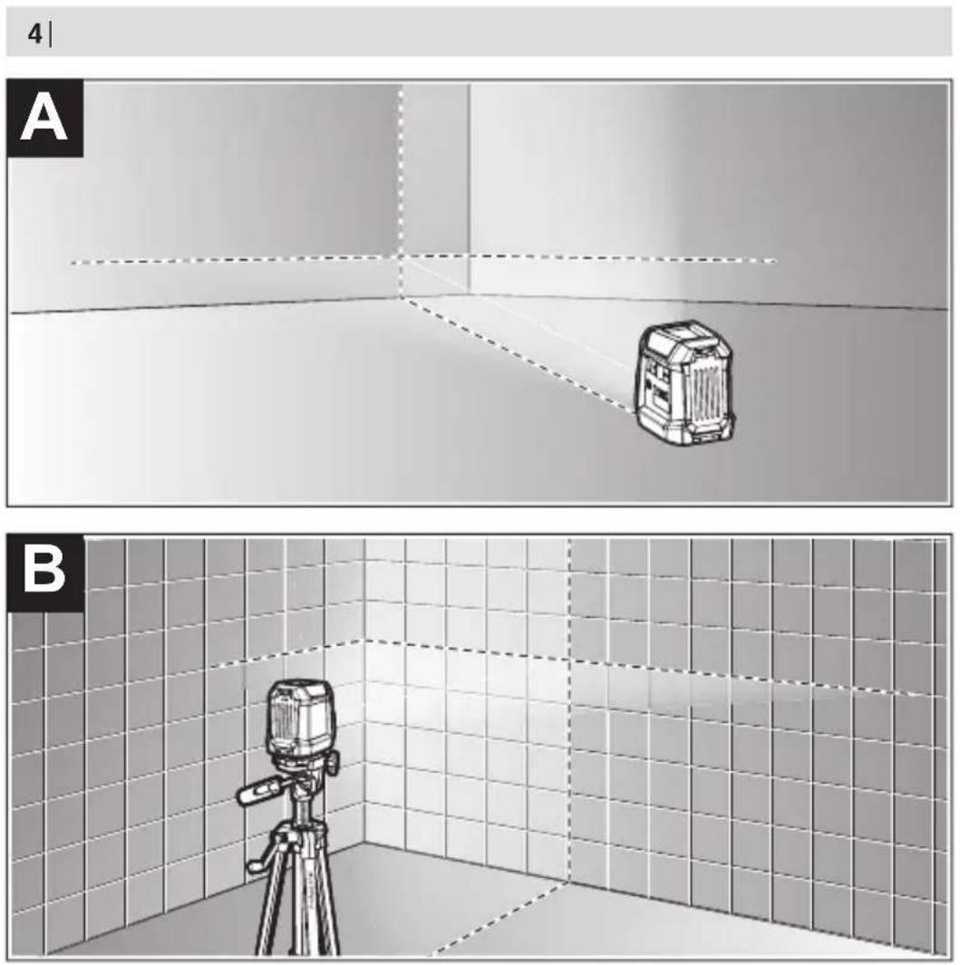
Automatic Levelling (see figures A-B)
Position the measuring tool on a level, firm support or attach it to a tripod (16).
After switching on, the automatic levelling function automatically compensates irregularities within the self-levelling range of ±3,5^ . The levelling is finished as soon as the laser lines are permanently lit (i.e. no longer flashing) and do not move anymore.
If automatic levelling is not possible, e.g. because the surface on which the measuring tool stands deviates by more than 3,5^ from the horizontal plane, the laser lines will flash continuously and quickly and the measuring tool will work without automatic levelling.
The laser lines remain switched on, but the two intersecting lines will no longer necessarily be perpendicular to each other.
To work with automatic levelling again, set up the measuring tool so that it is horizontal and wait for the self-levelling procedure to complete. As soon as the measuring tool is within the self-levelling range of ±3,5^ and is levelled in, the laser lines will light up continuously again.
In case of ground vibrations or position changes during operation, the measuring tool is automatically levelled again. Upon re-levelling, check the position of the horizontal or vertical laser line with regard to the reference points to avoid errors by moving the measuring tool.
Accuracy Check of the Measuring Tool
Influences on Accuracy
The largest influence is exerted by the ambient temperature. In particular, temperature differences that occur from the ground upwards can refract the laser beam.
In order to minimise thermal influences resulting from heat rising from the floor, it is recommended that you use the measuring tool on a tripod. In addition, position the measuring tool in the centre of the work surface, wherever this is possible.
In addition to external influences, device-specific influences (e.g. falls or heavy impacts) can also lead to deviations. For this reason, check the levelling accuracy each time before beginning work.
First check the height accuracy and levelling accuracy of the horizontal laser line, then the levelling accuracy of the vertical laser line.
Should the measuring tool exceed the maximum deviation during one of the tests, please have it repaired by a Bosch after-sales service.
14 | English
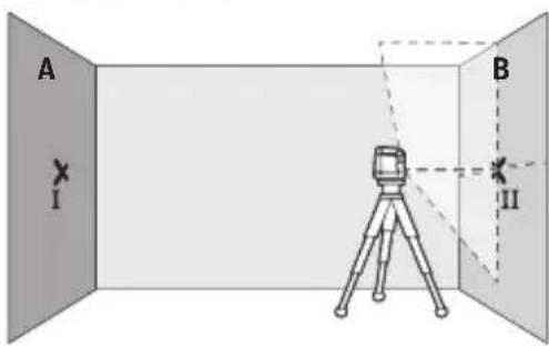
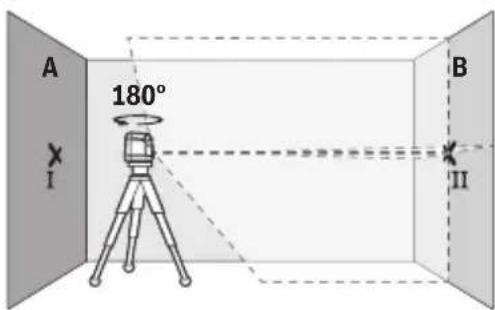
Checking the Height Accuracy of the Horizontal Line
For this check, you will need a free measuring distance of 5 m on firm ground between two walls (designated A and B).
- Mount the measuring tool close to wall A on a tripod, or place it on a firm, flat surface. Switch on the measuring tool.
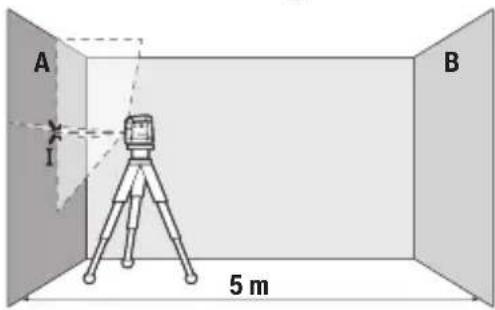
- Aim the laser at the closer wall A and allow the measuring tool to level in. Mark the middle of the point at which the laser lines cross on the wall (point I).
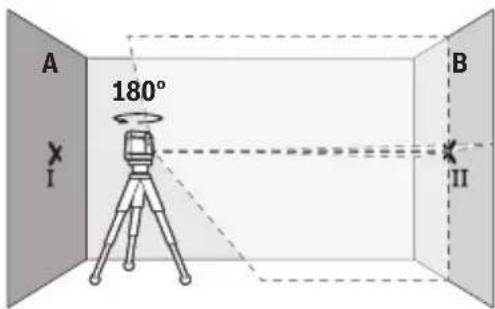
- Turn the measuring tool 180^ , allow it to level in and mark the point where the laser lines cross on the opposite wall B (point II).
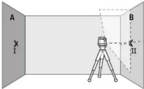
- Position the measuring tool – without rotating it – close to wall B, switch it on and allow it to level in.
- Align the height of the measuring tool (using the tripod or by placing objects underneath as required) so that the point where the laser lines cross exactly hits the previously marked point II on wall B.
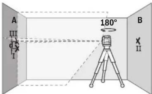
- Turn the measuring tool 180^ without adjusting the height. Aim it at wall A such that the vertical laser line runs through the already marked point I. Allow the measuring tool to level in and mark the point where the laser lines cross on wall A (point III).
- The discrepancy d between the two marked points I and III on wall A reveals the actual height deviation of the measuring tool.
The maximum permitted deviation on the measuring distance of 2 × 5 m = 10 m is as follows:
10 m × ±0.6 mm/m = ±6 mm. The discrepancy d between points I and III must therefore amount to no more than 6 mm.
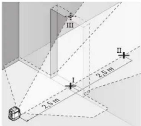
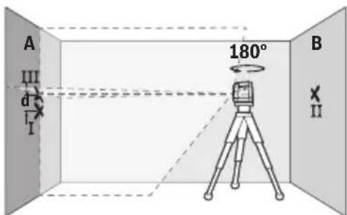
Checking the Level Accuracy of the Horizontal Line
For this check, you will need a free area of 5 × 5 m.
- Mount the measuring tool in the middle between walls A and B on a tripod, or place it on a firm, level surface. Switch the measuring tool on and allow it to level in.
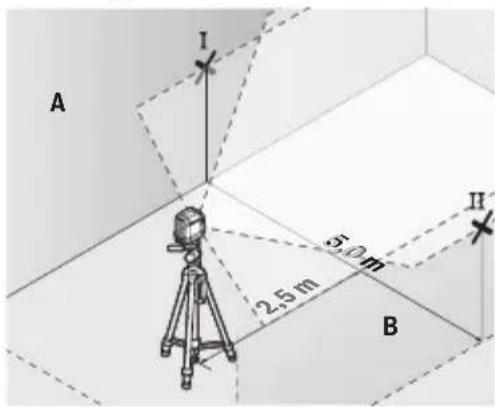
- At a distance of 2.5m from the measuring tool, mark the centre of the laser line on both walls (point I on wall A and point II on wall B).
16 | English
- Set up the measuring tool at a 5 m distance and rotated by 180^ and allow it to level in.
- Align the height of the measuring tool (using the tripod or by placing objects underneath as required) so that the centre of the laser line exactly hits the previously marked point II on wall B.
- Mark the centre of the laser line on wall A as point III (vertically above or below point I).
- The discrepancy d between the two marked points I and III on wall A reveals the actual horizontal deviation of the measuring tool.
The maximum permitted deviation on the measuring distance of 2 × 5 m = 10 m is as follows:
10 m × ±0.6 mm/m = ±6 mm. The discrepancy d between points I and III must therefore amount to no more than 6 mm.
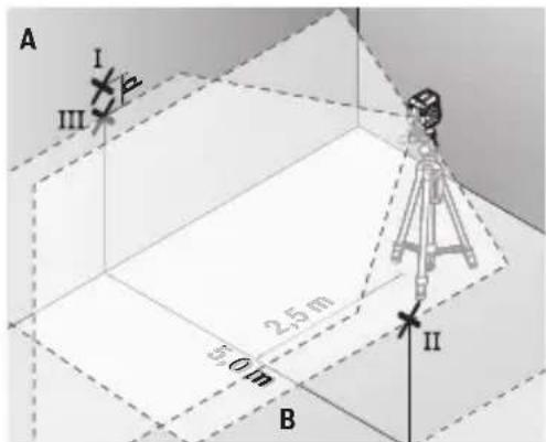
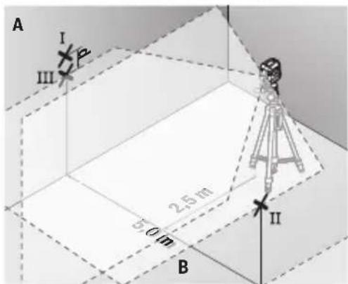
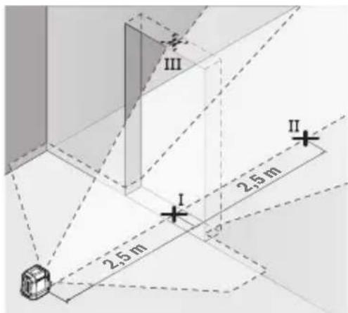
Checking the Level Accuracy of the Vertical Line
For this check, you will need a door opening (on solid ground) which has at least 2.5 m of space either side of the door.
- Place the measuring tool 2.5 m away from the door opening on a firm, flat surface (not on a tripod). Switch the measuring tool on and allow it to level in.
- Mark the centre of the vertical laser line on the floor of the door opening (point I), 5 m away on the other side of the door opening (point II) and on the upper edge of the door opening (point III).
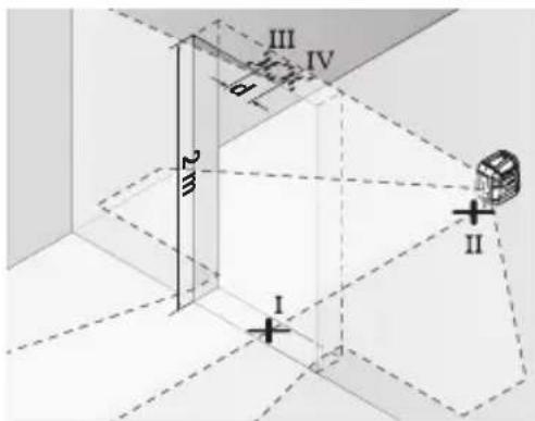
- Set up the measuring tool on the other side of the door opening, directly behind point II. Allow the measuring tool to level in and align the vertical laser line in such a way that its centre passes through points I and II exactly.
- Mark the centre of the laser line on the upper edge of the door opening as point IV.
- The discrepancy d between the two marked points III and IV reveals the actual vertical deviation of the measuring tool.
- Measure the height of the door opening.
You can calculate the maximum permitted deviation as follows:
Doubled height of the door opening × 0.6 mm/m
Example: At a door opening height of 2 m, the maximum deviation amounts to
2 × 2 m × ± 0.6 mm/m = ± 2.4 mm . The points III and IV must therefore be no further than 2.4 mm from each other.
Working Advice
▶ Only the centre of the laser line must be used for marking. The width of the laser line changes depending on the distance.
18 | English
Working with the Laser Target Plate
The laser target plate (13) improves visibility of the laser beam in unfavourable conditions and at greater distances.
The reflective surface of the laser target plate (13) improves visibility of the laser line. The transparent surface enables the laser line to be seen from behind the laser target plate.
Working with the Tripod
A tripod offers a stable, height-adjustable support surface for measuring. Place the measuring tool with the 1/4" tripod mount (1) on the thread of the tripod (16) or a conventional camera tripod. Tighten the measuring tool using the locking screw of the tripod.
Roughly align the tripod before switching on the measuring tool.
Laser Goggles
The laser goggles filter out ambient light. This makes the light of the laser appear brighter to the eye.
▶ Do not use the laser goggles (accessory) as protective goggles. The laser goggles make the laser beam easier to see; they do not protect you against laser radiation.
▶ Do not use the laser goggles (accessory) as sunglasses or while driving. The laser goggles do not provide full UV protection and impair your ability to see colours.
Maintenance and Service
Maintenance and Cleaning
Keep the measuring tool clean at all times.
Never immerse the measuring tool in water or other liquids.
Wipe off any dirt using a damp, soft cloth. Do not use any detergents or solvents.
The areas around the outlet aperture of the laser in particular should be cleaned on a regular basis. Make sure to check for lint when doing this.
Only store and transport the measuring tool in the protective pouch (17).
If the measuring tool needs to be repaired, send it off in the protective pouch (17).
After-Sales Service and Application Service
Great Britain
Tel. Service: (0344) 7360109
Malaysia
Tel.: (03) 79663194
You can find our service addresses and links to the repair service and spare parts ordering at www.bosch-pt.com/serviceaddresses
In all correspondence and spare parts orders, please always include the 10-digit article number given on the nameplate of the product.
Disposal
Measuring tools, rechargeable/non-rechargeable batteries, accessories and packaging should be sorted for environmental-friendly recycling.
Do not dispose of the measuring tools or battery packs/batteries with household waste.
Only for EU countries and United Kingdom:
Electrical and electronic equipment or used batteries that are no longer suitable for use must be collected separately and disposed of in an environmentally friendly manner. Use the designated collection systems. Incorrect disposal may cause harmful effects on the environment and human health, due to the potential presence of hazardous substances.
Français
Calle Robert Bosch No. 405
C.P. 50071 Zona Industrial,
Toluca - México, RFC: RBO910102QJ9
Tel.: (52) 55 528430-62
Tel.: 800 6271286
España
www.bosch-pt.com/serviceaddresses
| 6s8m3s6n m5s8g6y6n 603g7m6n | GLL2XG |
| m5s8j6nlu 61n3n | < 5 ∂m38, 500-540 6a |
| C6 | 5 |
| g6m3dnmj6s | 25 × 5 ∂m5o (l6m7m03y06b) |
| d6y6g ∂6s6n3n l d3j6 | 1/4" |
| 33j6s | |
| - m6m0nγδ-nm6y6n s3y6y6ms6y6m6n l d6mm3n | 3,7 3 |
| - d6y6s6y6n (6y6g) | 2 × 1,5 3 LR6 (AA) |
| ls6y6dsm m6y6m6n | 8 U |
| slu ^E) | 0,3 38 |
| 8m6d6n (l6m6d y x l6s6g x l6d6m6g) | 87 × 64 × 87 3a |
| q6s3z6n q6m6g | IP55 |
| m6m0nγδ-nm6y6n s3y6y6ms6y6m6n l d6mm3n(s6j6u7s6n) | BA 3.7V 1.0Ah A |
| ls6s6m6m6m6m6m6m6m6m6m6m6m6m6m6m6m6m6m6m6m6m6m6m6m6m6m6m6m6m6m6m6m6m6m6m6m6m6m6m6m6m6m6m6m6m6m6m6m6m6m6m6 | 1 607 A35 0N81 607 A35 17H |
| q6s6d6y6h6n d6y6g | USB Type-C® |
| m63m6g6y6y6y6m n 3s6y6m USB Type-C® | 1 600 A01 6A8 |
| 6m6n6s6m6m6m6m6m6m6m6m6m6m6m6m6m6m6m6m6m6m6m6m6m6m6m6m6m6m6m6m6m6m6m6m6m6m6m6m6m6m6m6m6m6m6m6m6m6m6m6m6 | 3,7 3 = |
| 6y6s6m6s | 1,0 s/uω |
| m63m6g6y6y6y6m n 3s6y6dmlu 6y6d3g6s6y6m6q6s6y6h6znlss | +10 °C ... +35 °C |
| m63m6g6y6y6y6m n 3s6y6dmlu 6y6d3g6s6y6m6q6s6y6h6znlss | -10 °C ... +45 °C |
| 33j6nlu d6mm3n ∂6y6y6l6m6m6m6m6m6m6m6m6m6m6m6m6m6m6m6m6m6m6m6m6m6m6m6m6m6m6m6m6m6m6m6m6m6m6m6m6m6m6m6m6m6m6m6m6m6m6m6m6m6 m6m6m6m6m6m6m6m6m6m6m6m6m6m6m6m6m6m6m6m6m6m6m6m6m6m6m6m6m6m6m6m6m6m6m6m6m6m6m6m6m6m6m6m6m6m6m6m6m6m6 33j6nlu d6mm3n ∂6y6y6l6m6m6m6m6m6m6m6m6m6m6m6m6m6m6m6m6m6m6m6m6m6m6m6m6m6m6m6m6m6m6m6m6m6m6m6m6m6m6m6m | |
| gs6m6s3s3m n ds6s | 5,0 3 = |
124 | ʃʌməŋɡən
| bsdmsb6n gmsgmynmn b03gmnomdn | GLL2XG |
| dn6ndsmynmn gsdmls13mynmn qg6n | 500 as |
A) 6n3g0m0n1u5d7dsm gns3s8m6n dgnndmgds dgn3g0m0glu smsbgmlusyngmn gsmgm3n6m0d0n1 ysdm (dgsg0m0nssp, d8n1u5b3g0n1 3n6q0s3n6n dgn4mfdg0g0n1 ysdm).
B) მოქმედებს ნიველორების მდგომარეობაში (0°)
C) ἀποπομόγμπο δδαδεβμμμόγιον οπασμηλύγικδυ διμάσμημί ρος βρμλυγμόγμ
ασμόγμί δασμόγμί (δασμόγμί, στάσμόγμί, διμόγμί, 33σμόγμί, δυλύ δασμόγμί
υβασμόγμί δασμόγμί υσμόγμί). Θβαδεβμαδεγμίον δδαδεβμμμόγιον ήγασμόγμί
δασμόγμί δασμόγμί ινδυλύγικύ ρσμόγμί.
D) ( \lambda_{3}g_{1}m_{1}g_{2}d_{1}n_{2}g_{3}s_{1}g_{2} ) , ( \lambda_{6}n_{1} ) ( \lambda_{6}n_{2} ) ( \lambda_{6}n_{3} ) ( \lambda_{6}n_{4} ) ( \lambda_{6}n_{5} ) ( \lambda_{6}n_{6} ) ( \lambda_{6}n_{7} ) ( \lambda_{6}n_{8} ) ( \lambda_{6}n_{9} ) ( \lambda_{6}n_{10} ) ( \lambda_{6}n_{11} ) ( \lambda_{6}n_{12} ) ( \lambda_{6}n_{13} ) ( \lambda_{6}n_{14} ) ( \lambda_{6}n_{15} ) ( \lambda_{6}n_{16} ) ( \lambda_{6}n_{17} ) ( \lambda_{6}n_{18} ) ( \lambda_{6}n_{19} ) ( \lambda_{6}n_{20} ) ( \lambda_{6}n_{21} ) ( \lambda_{6}n_{22} ) ( \lambda_{6}n_{23} ) ( \lambda_{6}n_{24} ) ( \lambda_{6}n_{25} ) ( \lambda_{6}n_{26} ) ( \lambda_{6}n_{27} ) ( \lambda_{6}n_{28} ) ( \lambda_{6}n_{29} ) ( \lambda_{6}n_{30} ) ( \lambda_{6}n_{31} ) ( \lambda_{6}n_{32} ) ( \lambda_{6}n_{33} ) ( \lambda_{6}n_{34} ) ( \lambda_{6}n_{35} ) ( \lambda_{6}n_{36} ) ( \lambda_{6}n_{37} ) ( \lambda_{6}n_{38} ) ( \lambda_{6}n_{39} ) ( \lambda_{6}n_{40} ) ( \lambda_{6}n_{41} ) ( \lambda_{6}n_{42} ) ( \lambda_{6}n_{43} ) ( \lambda_{6}n_{44} ) ( \lambda_{6}n_{45} ) ( \lambda_{6}n_{46} ) ( \lambda_{6}n_{47} ) ( \lambda_{6}n_{48} ) ( \lambda_{6}n_{49} ) ( \lambda_{6}n_{50} ) ( \lambda_{6}n_{51} ) ( \lambda_{6}n_{52} ) ( \lambda_{6}n_{53} ) ( \lambda_{6}n_{54} ) ( \lambda_{6}n_{55} ) ( \lambda_{6}n_{56} ) ( \lambda_{6}n_{57} ) ( \lambda_{6}n_{58} ) ( \lambda_{6}n_{59} ) ( \lambda_{6}n_{60} ) ( \lambda_{6}n_{61} ) ( \lambda_{6}n_{62} ) ( \lambda_{6}n_{63} ) ( \lambda_{6}n_{64} ) ( \lambda_{6}n_{65} ) ( \lambda_{6}n_{66} ) ( \lambda_{6}n_{67} ) ( \lambda_{6}n_{68} ) ( \lambda_{6}n_{69} ) ( \lambda_{6}n_{70} ) ( \lambda_{6}\bar{u}_{1}=0.00000000000000000000000000000000000000000000000000000000000000000000000000000000000000000000000000
E) ἐμδες προσηγα-παβγίαν αγγαγμαζομήν/αδιξικόγδον γαμγαγ
υλθμανο βγμλαξίγμιν βαμλυδο οργβδύσοχοςβος δρλυστηγδόγμος υλφικάδε
ασησοχοςδύ δασωσογδόγμον υλφικόγμον δαμάνος (11).
- ∂ndsmɔŋən ɒs8gɪn ɒsbɛmɡl 3gɒŋmʊ A ωs ∂ngʒən lʌðmđ bɡmʊsʃyml σʒən6b3gμoŋdɔn ləgjʊsdʒmɒdæmòs. ∂mδnədʒən ɒs8gɪŋmʊ n ʊbnʒdɔn ləsφs3ʒɔnlu ɒj6θ̃m (ˈŋɪm̃θ̃nɔn 1).

www.bosch-pt.com/serviceaddresses
- Usmerite laser na bliski zid A i pustite da se merni alat niveliše. Označite sredinu tačke na kojoj se laserske linije na zidu ukrštaju (tačka I).
- Okrenite merni alat za 180°, pustite da se niveliše i označite tačku ukrštanja laserskih linija na suprotnom zidu B (tačka II).
- Stavite merni alat - bez okretanja - blizu zida B, uključite ga i pustite da se niveliše.
- Merni alat usmerite u vis tako (pomoću stativa ili po potrebi podmetanjem), da tačka ukrštanja laserskih linija tačno pogađa prethodno označenu tačku II na zidu B.
- Merni alat okrenite za 180°, a da ne pomerate visinu. Usmerite ga prema zidu A, tako da vertikalna laserska linija prolazi kroz već označenu tačku I. Pustite merni alat da se niveliše i označite tačku ukrštanja laserskih linija na zidu A (tačka III).
– Označite na 2,5 m udaljenosti od mernog alata na oba zida sredinu laserske linije (tačka I na zidu A i tačka II na zidu B).
- Postavite merni alat za 180° okrenut na 5 m udaljenosti i iznivelišite ga.
– Merni alat usmerite uvis tako (pomoću stativa ili po potrebi podmetanjem) da sredina laserske linije tačno pogađa prethodno označenu tačku II na zidu B.
– Označite na zidu A sredinu laserske linije kao tačku III (vertikalno iznad odn. ispod tačke I).
- Razlika d između obe označene tačke I i III na zidu A predstavlja stvarno odstupanje mernog alata od horizontale.
Na mernoj deonici od 2 × 5 m = 10 m maksimalno dozvoljeno odstupanje iznosi: 10 m × ±0,6 mm/m = ±6 mm. Razlika d između tačaka I i III prema tome sme da iznosi maksimalno 6 mm.
Provera preciznosti nivelisanja vertikalne linije
Za kontrolu potreban Vam je otvor od vrata, kod kojih (na čvrstoj zemlji) sa svake strane vrata ima najmanje 2,5 m prostora.
– Postavite merni alat na 2,5 m rastojanja od otvora vrata na čvrstu ravnu podlogu (ne na stativ). Uključite merni alat i pustite ga da se niveliše.
- Označite sredinu vertikalne laserske linije na podu otvora za vrata (tačka I), na razdaljini od 5 m od druge strane otvora za vrata (tačka II) kao i na gornjoj ivici otvora za vrata (tačka III).

USB يت waterfront جهد
جهد منبع التيار مع
دما تكون درجات
الأucus Additional scope as they.