PCM 125 A1 - Cement mixer PARKSIDE - Free user manual and instructions
Find the device manual for free PCM 125 A1 PARKSIDE in PDF.

| Product Type | Cement mixer (concrete mixer) |
| Brand | Parkside |
| Model | PCM 125 A1 |
| Drum capacity | 120 liters |
| Power supply | 230 V ~ 50 Hz |
| Motor power | 0.55 kW |
| Full load current | 1 A |
| Max. drum speed | 26.6 min⁻¹ |
| Drum opening diameter | 385 mm |
| Protection type | IP45D |
| Protection class | II (double insulation) |
| Operating mode | S6 30% (intermittent duty with load) |
| Net weight | 45.4 kg |
| Guaranteed sound power level | 95 dB(A) |
| Drum material | Steel |
| Main functions | Mixing concrete and mortar, tiltable drum, transport wheels |
| Maintenance and cleaning | Clean with water and brush after use; do not immerse the motor block |
| Safety | Thermal safety cut-out, splash protection, On/Off switch |
| Spare parts and repairability | V-belts (wear parts), after-sales service via Scheppach |
| Intended use | Domestic use (DIY, garden) |
| Warranty | 3 years (conditions in manual) |
Frequently Asked Questions - PCM 125 A1 PARKSIDE
User questions about PCM 125 A1 PARKSIDE
0 question about this device. Answer the ones you know or ask your own.
Ask a new question about this device
Download the instructions for your Cement mixer in PDF format for free! Find your manual PCM 125 A1 - PARKSIDE and take your electronic device back in hand. On this page are published all the documents necessary for the use of your device. PCM 125 A1 by PARKSIDE.
USER MANUAL PCM 125 A1 PARKSIDE
natural_image
Line drawing of a concrete mixer with wheels and control panel (no text or symbols)
CEMENT MIXER - PCM 125 A1
BETONMISCHER - PCM 125 A1
BÉTONNIÈRE - PCM 125 A1
GB IE NI CY MT DE
CEMENT MIXER
Operating and Safety Instructions.
Translation of Original Operating Manual.
FR BE CH NL
BÉTONNIÈRE
Before reading, unfold the page with the illustrations and then familiarise yourself with all the functions of the product.
DE AT CH
2
natural_image
Pure mechanical diagram of a T-shaped structural component without any text, numbers, or symbols8
natural_image
Line drawing of a fan-shaped device with visible blades and central hub (no text or symbols)4
natural_image
Pure geometric diagram of concentric and overlapping circles without any text, numbers, or symbols9
natural_image
Technical line drawing of a mechanical component with concentric circular grooves and two protruding ports (no text or symbols)The image is too blurry to recognize any text content.
natural_image
Technical line drawing of a structural frame with two vertical supports and a central horizontal beam (no text or symbols)11
natural_image
Simple line drawing of a triangular support structure with no text or symbolsm = 311
natural_image
Simple line drawing of a mechanical component inside a circular frame (no text or symbols)The image is too blurry to recognize any text content.
natural_image
Technical line drawing of two mechanical components with internal compartments, connected by a dimension line (no text or symbols)2
flowchart
graph TD
    A["Two Circles"] --> B["5"]
    A --> C[" "]
    style A fill:#f9f,stroke:#333
    style B fill:#ccf,stroke:#333
    style C fill:#cfc,stroke:#333


3
other
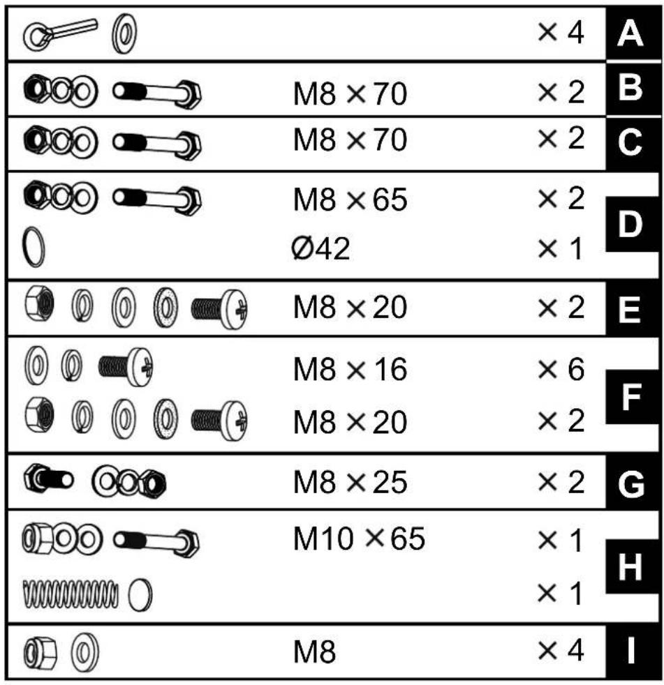
| Category | Item | Value | | :--- | :--- | :--- | | A | [O] | ×4 | | B | [O] | M8 ×70 | | B | [O] | ×2 | | C | [O] | M8 ×70 | | C | [O] | ×2 | | D | [O] | M8 ×65 | | D | [O] | Ø42 | | E | [O] | M8 ×20 | | E | [O] | ×2 | | F | [O] | M8 ×16 | | F | [O] | M8 ×20 | | F | [O] | ×2 | | G | [O] | M8 ×25 | | G | [O] | ×2 | | H | [O] | M10 ×65 | | H | [O] | ×1 | | I | [O] | M8 | ×4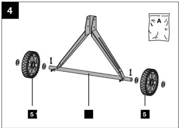
8
9
10
11
12
natural_image
Two identical mechanical device diagrams with no text or symbols13b
natural_image
Technical line drawing of a mechanical device with rotating components and support legs (no text or symbols)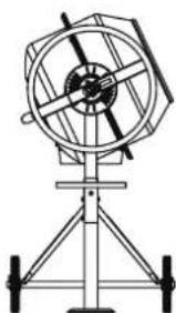
natural_image
Technical line drawing of a mechanical instrument with tripod base (no text or symbols)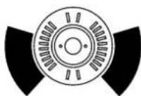
natural_image
Technical line drawing of a mechanical device with tripod base and circular components (no text or symbols)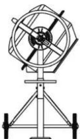
natural_image
Technical line drawing of a mechanical device with rotating components and support legs (no text or symbols)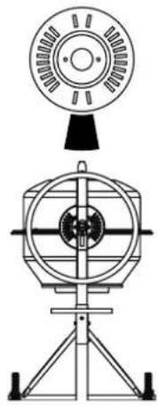
natural_image
Technical line drawing of a mechanical device with top and side views (no text or symbols)Table of contents: Page:
- Explanation of the symbols on the device ....2
- Introduction....4
- Device description (Fig. 1 - 13d) ....4
- Scope of delivery (Fig. 2 + 3)....4
- Proper use....4
- Safety instructions....5
- Technical data ....5
- Unpacking....6
- Assembly / Before commissioning....6
- Start-up....7
- Electrical connection....8
- Cleaning 8
- Transport 8
- Storage....9
- Maintenance....9
- Disposal and recycling....9
- Troubleshooting....10
- Warranty certificate .... 11
- Exploded view....123
- Declaration of conformity....124
1. Explanation of the symbols on the device
 | Read the operating manual before first use! |
 | Wear safety shoes. |
 | Wear safety gloves! |
 | Wear safety goggles! |
 | Wear dust protection mask! |
 | Wear hearing protection! |
 | Place the concrete mixer horizontally on level and firm floor! |
 | Concrete mixer must not be moved during operation! |
 | Concrete mixer may only be operated with the guard fully closed! |
 | Do not reach into the drum when it is moving! |
 | Caution! Danger of crushing on the sprocket in the locking disc. |
 | Do not start the motor until the drum has been fully loaded. |
 | Protect the environment! Take the leftover material to an authorized collection point. Make sure that it will not enter the sewage system, the ground or the water. |
 | Keep unauthorised persons and children away from the device! |
 | The device has protective insulation! Attention! The protection class is only maintained if original insulating materials are used during servicing and the insulation distances are not changed. |
 | Pull out the mains plug before cleaning or maintenance! |
 | Assembly aid! See: Assembly, Fitting the drum upper section. |
 | Specification of the sound power level in dB |
 | Protection class II |
 | The product complies with the applicable European directives. |
2. Introduction
MANUFACTURER:
Scheppach GmbH
Günzburger Straße 69
D-89335 Ichenhausen
DEAR CUSTOMER,
We hope your new tool brings you much enjoyment and success.
NOTE:
In accordance with the applicable product liability laws, the manufacturer of this device assumes no liability for damage to the device or caused by the device arising from:
- Improper handling,
- Failure to comply with the operating instructions,
• Repairs carried out by third parties, unauthorised specialists, - Installing and replacing non-original spare parts,
- Application other than specified,
- Failures of the electrical system in the event of the electrical regulations and VDE provisions 0100, DIN 57113 / VDE0113 not being observed.
Note:
Read the whole text of the operating manual before assembly and commissioning.
This operating manual should help you to familiarise yourself with your device and to use it for its intended purpose.
The operating manual includes important instructions for safe, proper and economic operation of the device, for avoiding danger, for minimising repair costs and downtimes, and for increasing the reliability and extending the service life of the device.
In addition to the safety instructions in this operating manual, you must also observe the regulations applicable to the operation of the device in your country.
Keep the operating manual at the device, in a plastic sleeve, protected from dirt and moisture. They must be read and carefully observed by all operating personnel before starting the work.
The device may only be used by personnel who have been trained to use it and who have been instructed with respect to the associated hazards. The required minimum age must be observed.
In addition to the safety instructions in this operating manual and the separate regulations of your country, the generally recognised technical rules relating to the operation of such machines must also be observed.
We accept no liability for accidents or damage that occur due to a failure to observe this manual and the safety instructions.
3. Device description (Fig. 1 - 13d)
- Drum
- Mixing unit
- On/off switch
- Motor unit
4a Screws - Transport wheels
- Machine stand
-
Swivel wheel
-
Foot
- Drum upper section
- Drum lower section
- Frame middle section
- Foot with wheel axle
- Locking disc
13a Holder - Bearing support
4. Scope of delivery (Fig. 2 + 3)
- Mixing unit (2)
- Motor unit (4)
- Transport wheels (5)
- Swivel wheel (7)
- Foot (8)
- Drum upper section (9)
- Drum lower section (10)
• Frame middle section (11) - Foot with wheel axle (12)
- Grating disc (13)
- Bearing support (14)
- 9x Enclosed accessories bag
- Operating manual
5. Proper use
The concrete mixer can be used for home work to mix concrete and mortar. The concrete mixer is only intended for private use in the home and garden.
The machine may only be used in the intended manner. Any use beyond this is improper. The user/operator, not the manufacturer, is responsible for damages or injuries of any type resulting from this.
An element of the intended use is also the observance of the safety instructions, as well as the assembly instructions and operating information in the operating manual.
Relevant accident prevention regulations and other generally recognized safety and technical rules must also be observed.
The machine may only be used, maintained or repaired by persons who are familiar with it and have been informed of the dangers. The manufacturer shall not be liable for damage resulting from unauthorised changes to the machine.
The machine may only be operated with original parts and original accessories from the manufacturer. The safety, operating and maintenance specifications of the manufacturer, as well as the dimensions specified in the technical data, must be observed.
Please note that our equipment was not designed with the intention of use for commercial or industrial purposes. We assume no guarantee if the device is used in commercial or industrial applications, or for equivalent work.
6. Safety instructions
General safety instructions
WARNING: When using power tools, the basic safety precautions below must be followed in order to reduce the risk of fire, electric shock, and personal injury.
Please read all instructions before working with this device.
- Observe all safety information and danger notices on the machine.
- Ensure that all of the safety and danger notices on the machine are complete and in legible condition.
- The safety equipment on the machine must not be disassembled or made unusable.
- Check the mains connection cables. Do not use defective connection cables.
- Check for correct function of the device before first use.
- Keep unauthorised persons and children away from the concrete mixer.
- Persons under the influence of alcohol, drugs or medication are not permitted to use the equipment.
- The operator is obligated to wear their personal protective equipment (PPE).
- Caution when working: Danger of injury due to rotating parts.
- Only carry out cleaning and maintenance work and rectify faults when the motor is switched off. Pull out the mains plug!
- Installation, repairs and maintenance work on the electrical equipment may only be carried out by electricians.
- All protective and safety equipment must be reassembled immediately after repair, maintenance is completed.
- Switch off the motor and pull out the mains plug before leaving the work area!
- Ensure adequate lighting. Poor lighting can significantly increase the danger of injury!
- In case of danger, switch the machine off and pull mains plug!
- Never place your hands on moving parts of the machine when it is switched on. There is a danger of entanglement due to the rotating drum and rotating mixing tools.
- The machine must not be operated while being moved to another location!
- The machine may only be positioned on a level surface!
- There is a danger of breathing in toxic vapours and dusts.
Additional safety instructions
- The concrete mixer may only be put into operation fully assembled.
- Check the connection cables for damage before commissioning.
- Wear safety shoes, gloves, safety goggles and a breathing mask.
- Keep hands and feet away from the moving parts.
- Do not reach into the mixing drum while it is running.
- Do not put any objects into the mixing drum while it is running, e.g. shovel or similar.
- Danger of injury when the mixing drum is rotating.
- The concrete mixer may only be operated with original spare parts.
- Repairs to the concrete mixer may only be carried out by authorised specialist companies.
- Do not leave ready-to-use concrete mixer unattended.
- Switch off the machine and pull out the mains, leaving the workstation.
Residual risks
The machine has been built according to the state-of-the-art and the recognised technical safety requirements. However, individual residual risks can arise during operation.
- Danger of injury due to rotating parts.
- Health hazard due to electrical power, with the use of improper electrical connection cables.
- Before performing setting or maintenance work, switch the motor off and unplug the mains plug.
• Furthermore, despite all precautions having been met, some non-obvious residual risks may still remain.
- Residual risks can be minimised if the “Safety Instructions” and the “Intended Use” together with the operating manual as a whole are observed.
- Avoid accidental start-ups of the machine: Make sure that the ON/OFF switch is set to "0" before inserting the plug into the socket.
- Use the tool that is recommended in this operating manual. This is how to ensure that your machine provides optimum performance.
- Keep your hands away from the working area when the machine is in operation.
Warning! This power tool generates an electromagnetic field during operation. This field can impair active or passive medical implants under certain circumstances.
In order to prevent the risk of serious or deadly injuries, we recommend that persons with medical implants consult with their physician and the manufacturer of the medical implant prior to cooperating the power tool.
7. Technical data
Motor 230 V\~ / 50Hz
Engine power 0.55 kW
Max. drum speed.... 26.6 rpm
Full load current 1 A
Capacity 120 l
Drum opening diameter 385 mm
Protection class IP45D
*Operating mode ...... S6 30%
Protection class ...... II
Weight 45.4 kg
Subject to technical changes!
*S6 30 %: Continuous duty with intermittent loading (operating time 10 min.)
In order to avoid impermissible overheating of the motor, the motor should be driven for only 30% of the operating time with the stipulated nominal power and must then continue to run with no load for the remaining 70% of the operating time.
Noise and vibration
⚠ Warning:
Noise can have serious effects on your health. If the machine noise exceeds 85 dB, please wear suitable hearing protection.
Noise data
The noise levels have been determined in accordance with EN ISO 3744:2010.
Sound pressure level L_pA 71.21 dB
Uncertainty K_pA 3.33 dB
Sound power level L_WA 91.21 dB
Uncertainty K_WA 3.33 dB
Guaranteed sound power level L_WA .....95 dB
8. Unpacking
- Open the packaging and carefully remove the device.
- Remove the packaging material, as well as the packaging and transport safety devices (if present).
- Check whether the scope of delivery is complete.
- Check the device and accessory parts for transport damage.
- If possible, keep the packaging until the expiry of the warranty period.
⚠️ DANGER
The device and the packaging are not children's toys! Do not let children play with plastic bags, films or small parts! There is a danger of choking or suffocating!
9. Assembly / Before commissioning
⚠ Attention!
Always make sure the device is fully assembled before commissioning!
In order to make assembly easier, assembly must be carried out by two persons.
The enclosed accessory bags (A to I) contain all the small parts required for assembly (see Fig. 3).
Tools required for assembly (not included in the scope of delivery):
- 2x Open-ended spanner, size 13
- 2x Open-ended spanner, size 16
- 1x Allen key, size 8
- 1x Combination pliers
• 1x Phillips screwdriver
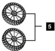
Fitting the transport wheels (5) (Fig.4) (enclosed accessory bag A)
- Insert a split pin through the inner hole of the wheel axle on both sides.
- Now push a washer onto the wheel axle on both sides.
- Then place the transport wheels (5) on both sides of the stand with wheel axle (12).
- Then push another washer onto the wheel axle on both sides.
- Insert a split pin through the outer hole of the wheel axle on both sides.
- Secure the transport wheels (5) by bending the split pins apart with suitable combination pliers (not included).
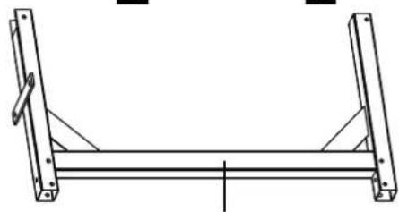
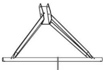
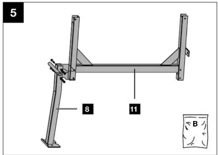
Installing the foot (8) on the frame middle section (11) (enclosed accessories bag B) (Fig. 5)
- Hold the foot (8) to the frame middle section (11) as shown. Select the holes such that the foot (8) is in the lower position.
- Push the two M8x70 hexagonal screws through the holes.
- Fix the screws with a washer, a spring washer and an M8 nut each.
- Tighten all screws using two open-ended spanners (size 13) (not included in the scope of delivery).
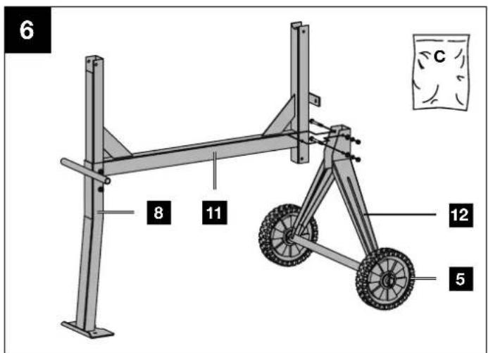
Installing the foot with wheel axle (12) and transport wheels (5) on the frame middle section (11) (enclosed accessories bag C) (Fig. 6)
- Hold the foot with wheel axle (12) to the frame middle section (11).
- Push the two M8x70 hexagonal screws through the holes.
- Fix the screws with a washer, a spring washer and an M8 nut each.
- Tighten all screws using two open-ended spanners (size 13) (not included in the scope of delivery).
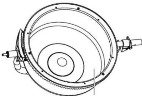
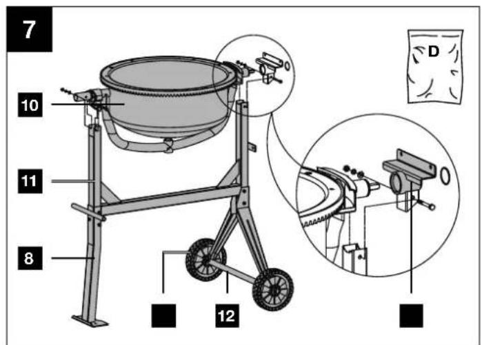
Fitting drum lower section (10) (enclosed accessories bag D) (Fig. 7)
- Fit the bearing support (14) onto the drum lower section (10) at the intended location.
- At the same time, insert the bearing of the drum lower section (10) with the premounted bearing support (14) into the opening of the machine stand (6). Make sure that the bearing support (14) is above the foot with wheel axle (12).
- Pay attention to the position of the holes.
- Push the two M8x65 hexagonal screws through the holes.
- Fix the screws with a washer, a spring washer and an M8 nut each.
- Then tighten all screws using one or two open-ended spanners (size 13) (not included in the scope of delivery).
- Fix the lower part of the drum (10) with the securing ring (see illustration).
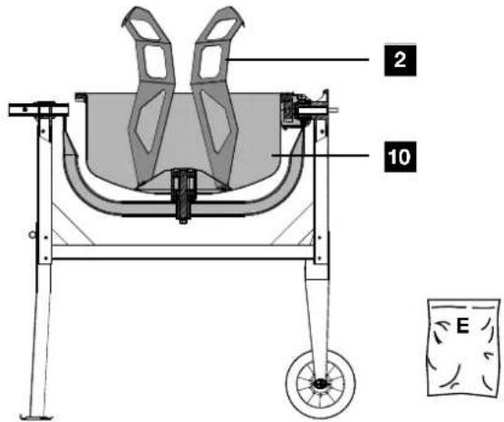
Fitting mixing unit (2) (enclosed accessories bag E) (Fig. 8)
- Insert an M8x20 Phillips screw from the outside through the lower part of the drum (10).
- Push one rubber washer each onto the Phillips-head screws just inserted in the lower drum part (10).
- Now place the mixing unit (2) on the mounted cross-head screws and fix it with one washer, one spring washer and one M8 nut each.
- The mixing unit (2) is not tightened until the upper part of the drum (9) has been mounted.
Note: In order to make correct installation of the mixing unit (2) easier, two arrows are attached to the upper and lower drum. If you are not sure whether the mixing unit has been installed correctly, you can test this. To do this, place the upper part of the drum (9) on the lower part of the drum (10) and turn them until the two arrows point towards each other.
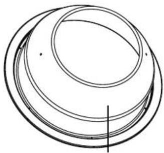
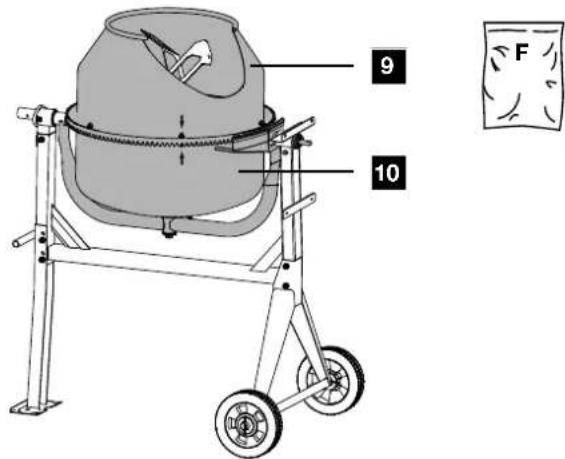
Fitting drum upper section (9) (enclosed accessories bag F) (Fig. 9)
- Put the upper part of the drum (9) on the lower part of the drum (10). Make sure that the fixing holes of the upper and lower drum align with each other.
Attention! The glued-on arrows mark the exact alignment of the drum lower section (10) and drum upper section (9). - Fix the upper part of the drum (9) by inserting the six M8x16 screws, the spring washers and washers.
- Then tighten the screws crosswise using a Phillips screw-driver (not included in the scope of delivery).
- Insert one M8x20 Phillips screw each through the upper part of the drum (9) from the outside.
- Push one rubber washer each onto the Phillips-head screws just inserted in the upper part of the drum (9).
- Attach the upper end of the mixing unit (2) by placing it on the Phillips screws just inserted. Fix it with one washer, one spring washer and one nut M8 on each.
- Finally, tighten all four screws in the lower drum section (10) and upper drum section (9) using a Phillips screwdriver and a size 13 open-end spanner (not included in the scope of delivery).
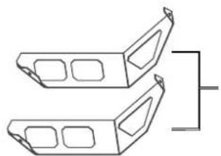
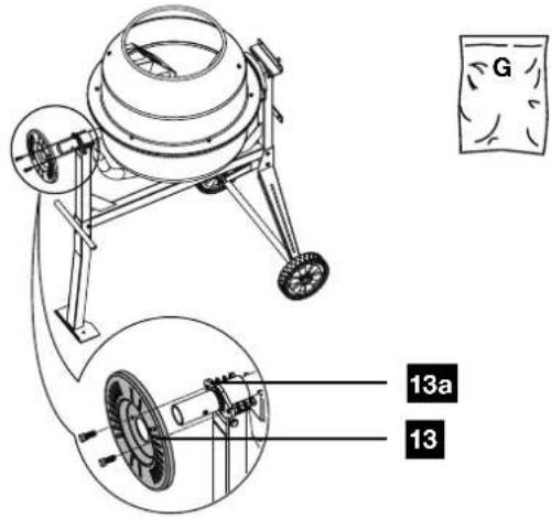
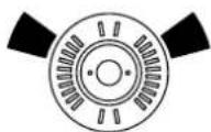
Installing the locking disc (13) (enclosed accessories bag G) (Fig. 10)
- Push the locking disc (13) onto the holder (13a).
- Fix them with the two hexagonal screws M8x25 and one washer, one spring washer and one nut M8 each.
- Then tighten all screws using one or two open-ended spanners (size 13) (not included in the scope of delivery).
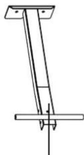
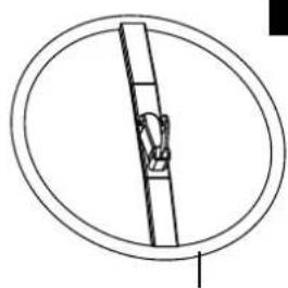
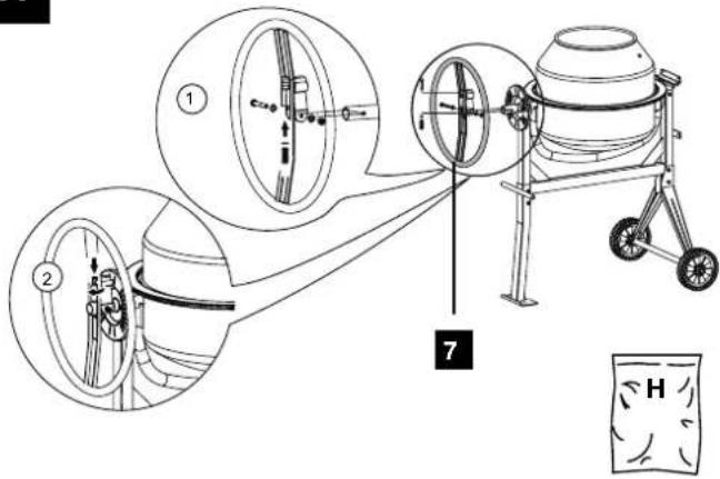
Installing the swivel wheel (7) (enclosed accessories bag H) (Fig. 11)
- Insert the washer and then the spring from below into the tube of the swivel wheel (7).
- Hold the spring in place with a finger.
- Place the swivel wheel (7) above the shaft of the drum lower section (10) so that the spring lies on the shaft.
- Push the swivel wheel (7) down until the holes in the shaft of the drum lower section (10) align with the holes in the swivel wheel (7).
- Fix the swivel wheel (7) with the M10x65 hexagon head screw, two washers and a stop nut.
- Then tighten the screw using two open-ended spanners size 16 (not included in the scope of delivery) until the swivel wheel (7) can still be tilted easily.
- Turn the cylinder screw of the tube clockwise using an 8 mm Allen key (not included in the scope of delivery) to adjust the spring tension.
Note: The swivel wheel (7) must be able to tilt when mounted on the shaft. It must be able to grip easily into the recesses of the locking disc (13).
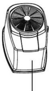
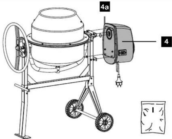
Installing the motor unit (4) (enclosed accessories bag I) (Fig. 12)
- Position the motor unit (4) such that the threaded bolts match the holes.
-
Now push the motor unit (4) completely onto the shaft.
-
Then fix the motor unit (4) with the four washers and the four M8 stop nuts. Use an open-ended spanner (size 13) for this (not included in the scope of delivery).
10. Start-up
⚠ Attention!
Always make sure the device is fully assembled before commissioning!
Only operate the concrete mixer if no parts are missing or faulty and if the connection cable is not damaged.
10.1 Setup
- Set up the concrete mixer horizontally on a level, non-tilting and firm surface. Prevent the machine from sinking into the ground.
- Do not set up the concrete mixer on the connection cable!
- Lay the connection cable so that it cannot be kinked, crushed or damaged in any other way.
Note:
The drum (1) must be able to swivel to the right and left. Make sure that a sufficient container (e.g. a mortar bucket) is beneath the drum (1) for emptying the drum (1). When setting up the machine, make sure that the mixing drum can be emptied freely.
10.2 Switching on/off (Fig. 1)
ATTENTION!
Danger of injury!
A rotating mixing drum can lead to injuries.
- Do not reach into the mixing drum while it is running.
-
Do not put any objects into the mixing drum while it is running (e.g. shovel or similar).
-
Connect a suitable extension cable to the connection cable of the concrete mixer.
- Plug the extension cable into the socket.
- Press the on/off switch (3) "I" (green button) to start the device.
- Press the on/off switch (3) "0" (red button) to switch off the device.
10.2.1. Thermal protection
With overloading or overheating, the protective shut-down integrated in the device switches off for safety reasons.
- Wait approx. 15 minutes until the motor has cooled down.
- Restart the device by pressing the on/off switch (green button).
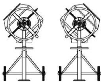
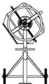
10.3 Adjusting the drum (1) (Fig. 1, Fig. 13a/13b)
The concrete mixer must be engaged in a certain mixing position for concrete and mortar production. Only the correct mixing position ensures the best mixing ratio and guarantees a trouble-free working process.
- Always hold the swivel wheel (7) firmly to adjust the drum (1).
- Release the swivel device by pulling the swivel wheel (7) towards you. The latch is released from the locking disc (13).
- Swivel the drum (1) to suit the consistency that corresponds with your mix.
• Fig. 13a: Drum position for the production of mortar
• Fig. 13b: Drum position for the production of concrete
- When the drum (1) is in the desired position, engage the pivoting wheel (7) into the locking disc (13) again.
10.4 Filling (Fig. 13a + 13b)
ATTENTION!
Health risk and danger of injury!
Breathing in dust can cause damage to health. Do not touch the cement or admixtures without protective gloves.
- Wear a breathing mask.
- Wear protective gloves and never reach into the mixing drum while it is running.
⚠ WARNING!
Tipping hazard!
Pay attention to the stability of the concrete mixer before filling.
- Only operate the concrete mixer on a firm, level (non-tilting) surface.
-
Do not change the location of the concrete mixer when filling or when the drum is running.
-
Press the on/off switch (3) "I" (green button) to start the device.
- Check the mixing position on the locking disc (13):
• Fig. 13a: Drum position for the production of mortar
• Fig. 13b: Drum position for the production of concrete
- Fill the mix while the drum is running (1). Do not overfill the drum (1). Caution! Danger from moving parts!
- Do not throw material into the drum (1) with great momentum in order to prevent it sticking to the underside of the drum (1). Feed in the material in small portions.
- Before filling, make sure that the opening of the drum (1) is aligned so that no mix can fall out of the drum (1).
Note: Ask a specialist for advice about the composition and quality of the mix.
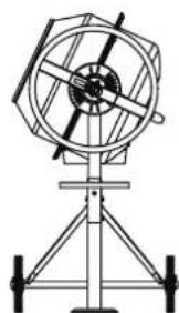
10.5 Emptying (fig. 13c)
- Place a sufficient container (e.g. a mortar bucket) beneath the drum (1). Make sure that no mix can get onto the floor.
- Unlock the swivelling device by pulling the pivoting handle (1) towards you. The latch is released from the locking disc (14).
- Now swivel the drum (1) downwards slowly to empty it.
11. Electrical connection
The electrical motor installed is connected and ready for operation. The connection complies with the applicable VDE and DIN provisions.
The customer's mains connection as well as the extension cable used must also comply with these regulations.
11.1 Damaged electrical connection cable
The insulation on electrical connection cables is often damaged.
This may have the following causes:
- Pressure points, where connection cables are passed through windows or doors.
-
Kinks where the connection cable has been improperly fastened or routed.
-
Places where the connection cables have been cut due to being driven over.
• Insulation damage due to being ripped out of the wall outlet. - Cracks due to the insulation ageing.
Such damaged electrical connection cables must not be used and are life-threatening due to the insulation damage.
Check the electrical connection cables for damage regularly. Ensure that the connection cables are disconnected from electrical power when checking for damage.
Electrical connection cables must comply with the applicable VDE and DIN provisions. Only use connection cables with the designation H07RN.
The printing of the type designation on the connection cable is mandatory.
For single-phase AC motors, we recommend a fuse rating of C 16A or K 16A for machines with a high starting current (from 3000 watts)!
12. Cleaning
⚠ WARNING!
Danger of injury!
The product can start unexpectedly and cause injuries.
- Switch off the motor before carrying out any clear maintenance work.
- Disconnect the mains plug before carrying out any cleaning work.
NOTE!
Risk of damage!
Damage to the motor can occur if water penetrates into the motor unit. Do not tap on the mixing drum with hard objects (hammer, shovel, etc.). A dented mixing drum impairs the mixing process and can be more difficult to clean.
- Clean the product with a brush or a scraper.
- Do not immerse the product in water or other liquids and do not spray the motor unit with a high-pressure cleaner.
We recommend that you thoroughly clean the inside and outside of the device directly after every use. Never remove dirt with a hammer, shovel or the like.
After each use of the concrete mixer:
- Clean the drum (1) with water and remove cement and mortar crusts with a brush or a scraper.
- To clean the inside of the drum, circulate a few shovels of gravel with water.
13. Transport
⚠ WARNING!
Danger of injury!
The product can start unexpectedly and cause injuries.
- Switch the motor off before transporting.
- Pull out the mains plug.
13.1 Vehicle transport (Fig. 13d)
-
Release the swivel device by pulling the swivel wheel (7) towards you. The latch is released from the locking disc (13).
-
Now place the drum (1) with the filling opening facing downwards.
- Remove the screws from the foot (8) and from the foot with wheel axle (12).
- Fold up the foot (8) and the foot with wheel axle (12).
- Secure the concrete mixer from sliding with a tension strap.
- Do not lift the concrete mixer with a crane.
13.2 Transport at the workplace (fig. 13d)
- Release the swivelling device by pulling the pivoting handle (1) towards you. The latch is released from the locking disc (13).
- Now place the drum (1) with the filling opening facing downwards.
- For a brief transport, tilt the concrete mixer gently and transport it on the transport wheels (5).
14. Storage
Store the device and its accessories in a dark, dry and frost-free place that is inaccessible to children. The optimum storage temperature is between 5 and 30°C.
Cover the concrete mixer to protect it from dust and moisture. Store the operating manual with the power tool.
15. Maintenance
⚠ WARNING!
Danger of injury!
The product can start unexpectedly and cause injuries.
- Switch the motor off before performing any work.
- Disconnect the mains plug before carrying out any maintenance work.
15.1 Checking belt tension (Fig. 12)
The belt tension is adjusted correctly in the factory. The belt tension cannot be readjusted.
- Remove the cover of the motor unit (4) by loosening the screws (4a) on the motor unit (4). Use a Phillips screwdriver for this (not included in the delivery).
- Check the belt tension. By pressing on the belt with your finger, the belt should give approx. 5 mm.
- Put the cover of the motor unit (4) back on and tighten the screws (4a). Use a Phillips screwdriver for this (not included in the delivery). When assembling, make sure that the seal is correctly inserted into the cover.
15.2 Replacing the belt
Belts are wearing parts that have to be replaced after a certain time.
- Remove the cover of the motor unit (4) by loosening the screws (4a) on the motor unit (4).
- Pull off the motor cover.
- The ribbed side of the new V-belt should face outwards when inserted. Make sure the lower part of the V-belt is installed first.
-
Check the belt tension. By pressing on the belt with your finger, the belt should give approx. 5 mm. It is not possible to retension the belt.
-
Put the cover of the motor unit (4) back on and tighten the screws (4a). When assembling, make sure that the seal is correctly inserted into the cover.
15.3 Connections and repairs
Connections and repair work on the electrical equipment may only be carried out by electricians.
Please provide the following information in the event of any enquiries:
- Type of current for the motor
• Machine data - type plate
15.4 Service information
With this product, it is necessary to note that the following parts are subject to natural or usage-related wear, or that the following parts are required as consumables.
Wearing parts*: Belt
* may not be included in the scope of delivery!
16. Disposal and recycling
Notes for packaging


The packaging materials are recyclable. Please dispose of packaging in an environmentally friendly manner.
Notes on the electrical and electronic equipment act (ElektroG)

Waste electrical and electronic equipment does not belong in household waste, but must be collected and disposed of separately!
- Used batteries or rechargeable batteries that are not installed permanently in the old device must be removed non-destructively before disposal! Their disposal is regulated by the battery act.
- Owners or users of electrical and electronic devices are legally obliged to return them after use.
- The end user is responsible for deleting their personal data from the old device being disposed of!
- The symbol of the crossed-out dustbin means that waste electrical and electronic equipment must not be disposed of with household waste.
-
Waste electrical and electronic equipment can be handed in free of charge at the following places:
-
Public disposal or collection points (e.g. municipal works yards)
- LIDL offers you return options directly in the share markets. Return and disposal are free of charge.
- Up to three waste electrical devices per type of device, with an edge length of no more than 25 centimetres, can be returned free of charge to the manufacturer without prior purchase of a new device from the manufacturer or taken to another authorised collection point in your vicinity.
- Further supplementary take-back conditions of the manufacturers and distributors can be obtained from the respective customer service.
- If the manufacturer delivers a new electrical device to a private household, the manufacturer can arrange for the free collection of the old electrical device upon request from the end user. Please contact the manufacturer's customer service for this.
- These statements only apply to devices installed and sold in the countries of the European Union and which are subject to the European Directive 2012/19/EU. In countries outside the European Union, different regulations may apply to the disposal of waste electrical and electronic equipment.
- Troubleshooting
| Fault Possible cause Remedy | ||
| Engine does not start | No mains voltage Check the safeguard | |
| Connection cable defective Have checked or replaced by an electrician | ||
| Engine switches off | Engine overloaded Let the engine cool down | |
| Supply and exhaust air openings on the motor unit are contaminated | Clean supply and exhaust air openings | |
| Engine runs, drum stands still | V-belt slipping Replace V-belt | |
18. Warranty certificate
Dear Customer,
All of our products undergo strict quality checks to ensure that they reach you in perfect condition. In the unlikely event that your device develops a fault, please contact our service department at the address shown on this guarantee card. Of course, if you would prefer to call us then we are also happy to offer our assistance under the service number printed below. Please note the following terms under which guarantee claims can be made:
- These guarantee terms cover additional guarantee rights and do not affect your statutory warranty rights. We do not charge you for this guarantee.
- Our guarantee only covers problems caused by material or manufacturing defects, and it is restricted to the rectification of these defects or replacement of the device. Please note that our devices have not been designed for use in commercial, trade or industrial applications. Consequently, the guarantee is invalidated if the equipment is used in commercial, trade or industrial applications or for other equivalent activities. The following are also excluded from our guarantee: compensation for transport damage, damage caused by failure to comply with the installation/assembly instructions or damage caused by unprofessional installation, failure to comply with the operating instructions (e.g. connection to the wrong mains voltage or current type), misuse or inappropriate use (such as overloading of the device or use of non-approved tools or accessories), failure to comply with the maintenance and safety regulations, ingress of foreign bodies into the device (e.g. sand, stones or dust), effects of force or external influences (e.g. damage caused by the device being dropped) and normal wear resulting from proper operation of the device.
The guarantee is rendered null and void if any attempt is made to tamper with the device.
- The guarantee is valid for a period of 3 years starting from the purchase date of the device. Guarantee claims should be submitted before the end of the guarantee period within two weeks of the defect being noticed. No guarantee claims will be accepted after the end of the guarantee period. The original guarantee period remains applicable to the device even if repairs are carried out or parts are replaced. In such cases, the work performed or parts fitted will not result in an extension of the guarantee period, and no new guarantee will become active for the work performed or parts fitted. This also applies when an on-site service is used.
- In order to assert your guarantee claim, please contact the service partner shown below. If the complaint is within the guarantee period, we will provide you with a return slip, with which you can return your defective device free of charge to us. It would help us if you could describe the nature of the problem in as much detail as possible. If the defect is covered by our guarantee then your device will either be repaired immediately and returned to you, or we will send you a new device.
Of course, we are also happy offer a chargeable repair service for any defects which are not covered by the scope of this guarantee or for units which are no longer covered. To take advantage of this service, please send the device to our service address.
18.1 Processing of warranty claims
To ensure that your request is processed quickly, please follow the instructions below:
- Please have the receipt and article number (e.g. IAN 471955_2407) ready as proof of purchase for all enquiries.
- Please refer to the type plate on the product, an engraving on the product, the title page of your instructions (bottom left) or the sticker on the back or underside of the product for the article number.
- If functional faults or other defects occur, first contact the service department named below by telephone or e-mail.
- You can then send a product recorded as defective to the service address provided to you free of charge, enclosing the proof of purchase (receipt) and stating what the defect is and when it occurred.
- You can view and download these and many other manuals at parkside-diy.com. This QR code will take you directly to parkside-diy.com. Select your country and use the search mask to search for the operating instructions. Enter the article number (IAN) 471955_2407 to access the operating instructions for your article.
Service contact (GB):
Name: Forest Park & Garden
Coed Court, Taffsmead Road
Treforest, Ind. Estate,
Pontypridd CF375SW
Tel: 00800 4003 4003
E-Mail: service.GB@scheppach.com
Location: Great Britain
Service contact (CY):
Name: GEORGE C SOLOMONIDES
& SON LTD
PO.BOX 56236 / 169, LEONTIOS A'
GR - 3022 LIMASSOL/CYPRUS
Tel: 00800 4003 4003
E-Mail: service.CY@scheppach.com
Location: Cyprus
Service contact (IE):
Name: Forest Park & Garden
Coed Court, Taffsmead Road
Treforest, Ind. Estate,
Pontypridd CF375SW
Tel: 00800 4003 4003
E-Mail: service.IE@scheppach.com
Location: Great Britain
Service contact (IT):
Name:TeleMarComEuropean
Services GmbH
Am Ziegelweiher 24
DE - 61130 Nidderau
Tel: 00800 4003 4003
E-Mail: service.IT@scheppach.com
Location: Germany
Service contact (NI):
Name: Forest Park & Garden
Coed Court, Taffsmead Road
Treforest, Ind. Estate,
Pontypridd CF375SW
Tel: 00800 4003 4003
E-Mail: service.NI@scheppach.com
Location: Great Britain

Inhalt:
Seite:
Günzburger Straße 69
D-89335 Ichenhausen
VEREHRTER KUNDE,
Günzburger Straße 69
D-89335 Ichenhausen
CHER CLIENT,
Günzburger Straße 69
D-89335 Ichenhausen
GEACHTE KLANT,
Servicecontact (NL):
Naam: TeleMarCom European Services GmbH
Am Ziegelweiher 24
DE - 61130 Nidderau
Telefoon: 00800 4003 4003
E-mail: service.NL@scheppach.com
Servicecontact (BE):
Naam: TeleMarCom European Services GmbH
Am Ziegelweiher 24
DE - 61130 Nidderau
Telefoon: 00800 4003 4003
E-mail: service.BE@scheppach.com
Günzburger Straße 69
Günzburger Straße 69
D-89335 Ichenhausen, Germania
EGREGIO CLIENTE,
Günzburger Straße 69
D-89335 Ichenhausen
VÁŽENÝ ZÁKAZNÍKU,
Günzburger Straße 69
D-89335 Ichenhausen
VÁŽENÝ ZÁKAZNÍK,
Günzburger Straße 69
D-89335 Ichenhausen
KEDVES ÜGYFELÜNK!
Günzburger Straße 69
D-89335 Ichenhausen
SZANOWNY KLIENCIE,
Günzburger Straße 69
D-89335 Ichenhausen, Tyskland
KÆRE KUNDE,
EU Declaration of Conformity
Translation of the original EU Declaration of Conformity
Standard references:
EN ISO 12100:2010; EN 60204-1:2018; EN 12151:2007; EN IEC 55014-1:2021; EN IEC 55014-2:2021; EN IEC 61000-3-2:2019+A1:2021; EN 61000-3-3:2013+A1:2019+A2:2021
This declaration of conformity is issued under the sole responsibility of the manufacturer.
Subject to change without notice
Documents registrar: Tobias Ihle
Günzburger Str. 69, D-89335 Ichenhausen

CE
SCHEPPACH GMBH
Günzburger Str. 69
D-89335 Ichenhausen

FSC
www.fsc.org
MIX