
PerfectPaint 800 EasyGo - Paint spray CECOTEC - Free user manual and instructions
Find the device manual for free PerfectPaint 800 EasyGo CECOTEC in PDF.

| Product type | Paint sprayer (spray gun) |
| Brand | Cecotec |
| Model | PerfectPaint 800 EasyGo |
| Reference | EU01_102254 |
| Power | 800 W |
| Power supply | 230 V ~ 50 Hz |
| Tank capacity | 800 ml |
| Maximum viscosity | 120 DIN/s |
| Maximum flow rate | 1100 ml/min |
| Included nozzles | 1.0 mm, 1.5 mm, 2.0 mm, 3.0 mm |
| Spray patterns | Vertical flat spray, horizontal flat spray, circular spray |
| Flow adjustment | Yes, via a knob on the trigger |
| Compatible materials | Water-based paints, solvent-based paints, primers, varnishes, two-component paints, etc. |
| Cleaning function | Cleaning connection for water rinsing |
| Blowing/inflating function | Powder purge connector for cleaning and inflating |
| Included accessories | Carrying strap, funnel, viscosity cup, brush, needle, filter, etc. |
Frequently Asked Questions - PerfectPaint 800 EasyGo CECOTEC
Fill the tank using the provided funnel.
User questions about PerfectPaint 800 EasyGo CECOTEC
0 question about this device. Answer the ones you know or ask your own.
Ask a new question about this device
Download the instructions for your Paint spray in PDF format for free! Find your manual PerfectPaint 800 EasyGo - CECOTEC and take your electronic device back in hand. On this page are published all the documents necessary for the use of your device. PerfectPaint 800 EasyGo by CECOTEC.
USER MANUAL PerfectPaint 800 EasyGo CECOTEC
natural_image
Product photo of an OBCOMAC spray gun with black hose and blue handle (no visible text or symbols)Safety instructions 11
- Parts and components 100
- Before use 100
- Operation 103
- Cleaning and maintenance 105
- Troubleshooting 107
- Technical specifications 108
- Disposal of old electrical and electronic appliances 109
- Technical support and warranty 109
- Copyright 109
- Declaration of Conformity 110
SOMMAIRE
EN · The coding in this manual is generic and applies to all code variants of the appliance.
Read these instructions thoroughly before using the appliance. Keep this instruction manual for future reference or new users.
- WARNING: read all safety warnings, instructions, figures and specifications supplied with this power tool. Failure to follow all instructions listed below may result in electric shock, fire and/or serious injury.
- WARNING: read all safety warnings and instructions marked with the symbol.
- Keep all safety warnings and instructions for future reference.
1) Work area safety
a. Keep the work area clean and well illuminated.
b. Do not operate power tools in explosive environments, such as in the presence of flammable liquids, gases or dust. Power tools create sparks that can light dust or fumes.
c. Keep children and bystanders away while operating a power tool. Distractions can make you lose control of the tool.
2) Electrical safety
a. The power tools plugs must match the socket. Never modify the plug. Do not use adapter plugs with earthed power tools. The unmodified plugs and the suitable sockets reduce the risk of electric shock.
b. Avoid body contact with earthed surfaces, like pipes, radiators, stoves and refrigerators. There is a higher risk of electric shock if your body is in touch with grounded surfaces.
c. Do not expose power tools to rain or wet conditions. The water inlet in a power tool increases the risk of electric shock.
3) Personal safety
a. Stay alert and use common sense when using a power tool. Do not use power tools if you are tired or under the influence of drugs, alcohol or medication. Lack of attention while operating power tools can result in serious personal injury.
b. Use personal protective equipment. Always wear eye protection. Protective gear, like dust mask, non-slip safety footwear, helmet or hearing protection, used under the appropriate conditions, will reduce the risk of injuries.
c. Avoid unintentional start-up. Make sure the switch is in Off position before connecting the tool to a power source and/or battery, or before picking it up or transporting it. Carrying power tools with your finger on the switch or plugging in power tools with the switch in the On position will result in injuries.
d. Remove any spanners or wrenches before switching on the power tool. Leaving a spanner or wrench in a rotary piece of the tool may cause injuries.
e. Do not exert too much force when using the tool. Keep your feet firmly on the ground and always maintain your balance. This will provide better control of the electric tool in unexpected situations.
f. Wear appropriate clothes. Do not wear loose clothing or jewellery. Keep hair and clothing away from moving parts. Loose clothing, jewellery or long hair can get caught in moving parts.
g. The confidence gained from frequent use of tools should not be a reason for ignoring general security principles. A careless action can cause serious injury within a fraction of a second.
4) Use and care of electric tools
a. Do not force the power tool. Use the appropriate power tool for the project. The proper electric tool will make your work better and safer using the speed for which it was designed.
b. Do not use the power tool if the switch does not switch it on and off. Any electric tool that cannot be controlled with a switch is dangerous and must be repaired.
c. Disconnect the plug from the power source and/or remove the battery pack, if detachable, from the power tool before making any adjustments, changing accessories or storing it. These preventive safety measures reduce the risk of the power tool starting up accidentally.
d. Store idle electric tools out of the reach of children and do not allow people unfamiliar with the power tool or these instructions to operate the power tool. Power tools are dangerous in the hands of inexperienced users.
e. Maintenance of power tools and accessories. Check if the moving parts are misaligned or stuck, if there are broken pieces or any other condition that may affect the power tool's operation. If damaged, have the power tool repaired before use. Many accidents are caused by poorly maintained power tools.
f. Use the power tool, accessories, etc. according to these instructions, taking into account the working conditions and the work to be carried out. Use of the power tool for
operations other than those intended could result in a hazardous situation.
g. Keep handles and gripping surfaces dry, clean and free of oil and grease. Slippery handles and grasping surfaces do not allow safe handling and control of the tool in unexpected situations.
5) Service
a. Have your power tool repaired by a qualified technician using only original replacement parts. This will ensure that the power tool remains safe.
6) General precautions
- Hold the electric tool by the insulated gripping surfaces when performing an operation in which the tool may come into contact with exposed wiring. The tool must not come into contact with live wires. This may result in electric shock.
- Keep the power tool and its accessories away from hot surfaces.
- Do not allow untrained people use the power tool and its accessories.
- People with physical or mental disabilities must not use power tools or accessories without supervision.
- Children must not play with, clean or try to repair the power tool and its accessories.
- Allow the tool to cool down completely after use before touching it.
- Always wait until all moving parts have stopped after working with the tool.
7) Additional safety instructions for the spray gun
a. Do not spray flammable materials.
b. Take note of possible risks posed by the spray material. Observe the markings on the container or the manufacturer's information regarding the spray material.
c. Unknown materials could create hazardous conditions.
d. Always wear a dust mask when using the spray gun.
e. It is recommended to wear hearing protection during operation.
f. Do not clean the spray gun with flammable solvents.
g. Warning! Disconnect the mains plug from the socket before making any adjustments, cleaning or maintenance.
h. If the power cord of this power tool is damaged, it must be replaced by the manufacturer.
i. If it is necessary to replace the carbon brushes, have them replaced by a qualified technician (always replace both brushes at the same time).
| Symbol Meaning | |
 | Warning |
 | Warning: risk of electric shock! |
 | Indicates tips for use and other particularly useful information. |
 | Class II tool |
 | Wear a protective mask |
 | Refer to the instruction manual/brochure |
 | Wear protective gloves |
 | Wear eye protection |
INSTRUCTIONS DE SÉCURITÉ
- Carrying strap
- Air hose
- ON/OFF switch
- Main unit
- Material volume control
- Trigger
- Grass catcher handle
- Spray gun front assembly
- Clamping nut
- Air nozzle
- 2.0 mm nozzle
- Paint tank
- Dust-proof cover.
- Power cord
- 1.0 mm nozzle
- 1.5 mm nozzle
- 3.0 mm nozzle
- Cleaning connector
- Powder blowing connector
- Cleaning needle
- Viscosity vessel
- Cleaning brush
NOTE:
The graphics in this manual are schematic representations and may not exactly match the product.
2. BEFORE USE
- This appliance is packaged in a way as to protect it during transport. Take the appliance out of its box and remove all packaging materials. You can keep the original box and other packaging elements in a safe place. This will help you prevent damage to the machine when transporting it in the future. In case the original packaging is disposed of, make sure all packaging materials are recycled accordingly.
- Make sure all parts and components are included and in good conditions. If there is any piece missing or in bad conditions, contact the official Cecotec Technical Support Service immediately.
Box content
- Compressor equipment
- Trigger gun
- Tube
- Belt
- 4 nozzles
- Container lid
- Filling funnel
- Filter
- Cleaning accessories
- Instruction manual
- Do not remove the serial number of the appliance in order to keep a correct traceability of it in case of assistance.
Field of application
This product is suitable for use with water-based and solvent-based paints, topcoats, primers, 2-component paints, clear coats, automotive topcoats, stain sealers and wood sealer-preservatives. It is also compatible with all coating materials bearing the red Perfect Spray logo.
Coating materials suitable for use
Interior wall painting (dispersions and latex paint)
Coating materials unsuitable for use
Materials containing highly abrasive components, facade paint, caustic solutions and acidic coating substances. Flammable materials.
The following materials can only be processed with optional accessories:
Water-based and solvent-based paints, topcoats, primers, 2-component paints, clear coats, automotive topcoats, stain sealers and wood sealer-preservatives.
Workplace preparation
⚠️ Plugs and sockets must be masked! Risk of electric shock as a consequence of spray entering the socket!
⚠ Mask off all areas and objects that should not be painted or remove them from the work area. No liability is assumed for damage caused by overspray.
Silicate corrodes glass and ceramic surfaces on contact! Therefore, all these surfaces must be completely covered.
i
When using adhesive tape, pay attention to the quality of the tape to ensure good adhesion
ENGLISH
without damaging surfaces.
Avoid using too strong adhesive tape on wallpaper and painted surfaces to prevent damage during removal. When removing the tape, do so slowly and evenly, avoiding sudden movements. Do not leave the tape on surfaces longer than necessary to minimize the risk of leaving residue on removal.
Be sure to follow the tape manufacturer's instructions to ensure proper use and best results.
Coating material preparation
For best results, use the spray material at room temperature or diluted with warm water. Do not heat the spray material above 40 °C. Interior wall paints can be sprayed undiluted or slightly diluted using the spray attachment provided.
- Stir the material well and dilute it in the container according to the recommended dilution, using an agitator if available.
| Pulverized material Recommended dilution | |
| Interior wall painting (dispersions and latex paint) dilute from 0-10 %. | |
- If the speed is too low even at the maximum flow setting, dilute the material in 5 - 10 % increments until the feed rate meets your requirements (while respecting the maximum allowable dilution specified by the manufacturer).
Material viscosity: Checking and adjusting
A. This product is designed to use spray materials with a maximum viscosity of 120 DIN/sec. It is essential to check the viscosity of the material before using the spray gun to ensure optimum performance and a quality finish.
B. How to measure viscosity:
- Fill the viscosity cup with the material to be sprayed. Fig. 2
- Allow the material to flow out of the viscosity cup.
- Measure the time in seconds it takes for the material to stop flowing completely out of the viscosity cup. This time is the DIN/sec value.
C. Viscosity adjustment:
- If the measured value is higher than 120 DIN/sec, dilute the material gradually with a suitable diluent.
- Repeat the measurement after each addition of diluent until a value equal to or less than 120 DIN/sec is obtained.
- If the paint takes longer than recommended to empty from the viscosity cup, further thinning will be necessary. Add a small amount of the appropriate thinner to the paint and repeat the viscosity test until the desired value is reached.
- Please note: Use only thinners compatible with the type of spray material. Refer to the material manufacturer's instructions to identify the appropriate thinner.
- The use of an incorrect thinner can cause lumps to form and clog the product.
- WARNING: Never mix synthetic resin paints with nitro thinners.
- Warning: Do not spray materials containing granules or solid particles, as they may
clog the product and damage the equipment.
Table of recommended viscosities (DIN/sec) according to the type of material:
| Material type | Recommended viscosity (DIN/sec) |
| Solvent-based paints 15-50 | |
| Primers 25-50 | |
| Paint stripper No need to dilute | |
| Two-component paint 20-50 | |
| Varnishes 15-40 | |
| Water-based paint 20-40 | |
| Automotive topcoats 20-40 | |
| Wood preservatives No need to dilute | |
| Clear sealants, polyurethane and stains No need to dilute | |
| Enamel, latex paint 25-40 |
3. OPERATION
Before connecting the device to the mains, make sure that the supply voltage corresponds to the value indicated on the rating plate.
- Attach the carrying strap to the unit. Fig. 3
- Unscrew the container from the spray gun.
-
Align the suction tube. Fig. 4
-
If the suction tube is correctly positioned, the contents of the container can be sprayed with almost no residue. When spraying horizontal surfaces, rotate the suction tube forward as shown in figure 4 (A). When spraying overhead objects, turn the suction tube backwards as shown in figure 4 (B).
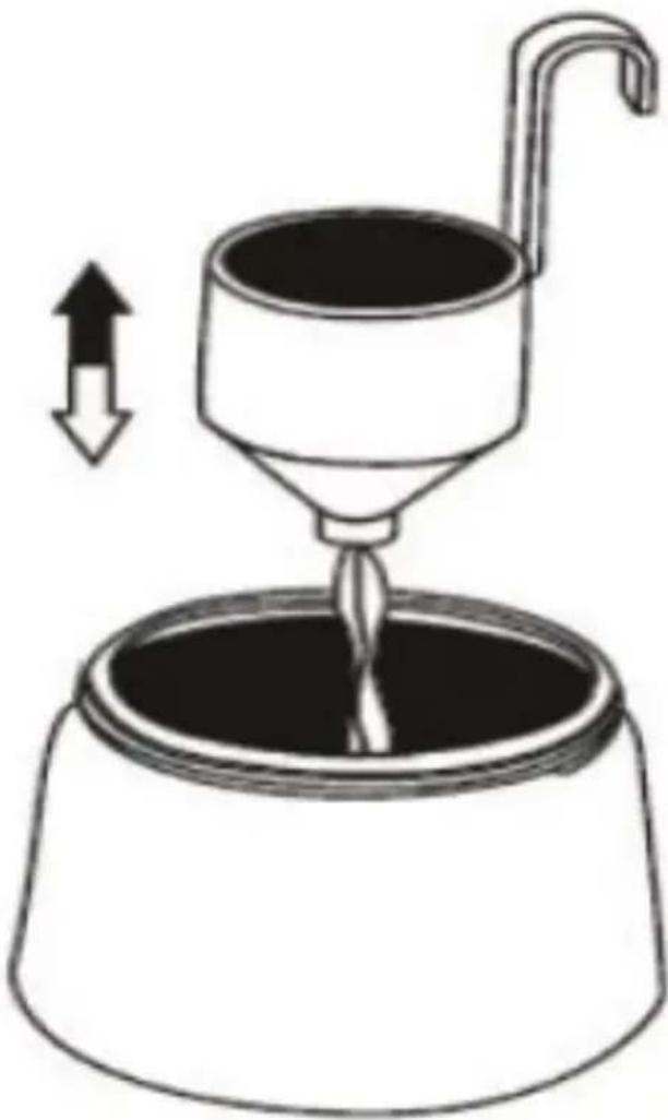
-
Place the paint tank on a paper base and pour the prepared coating substance using the filling funnel. Screw the tank firmly onto the spray gun.
-
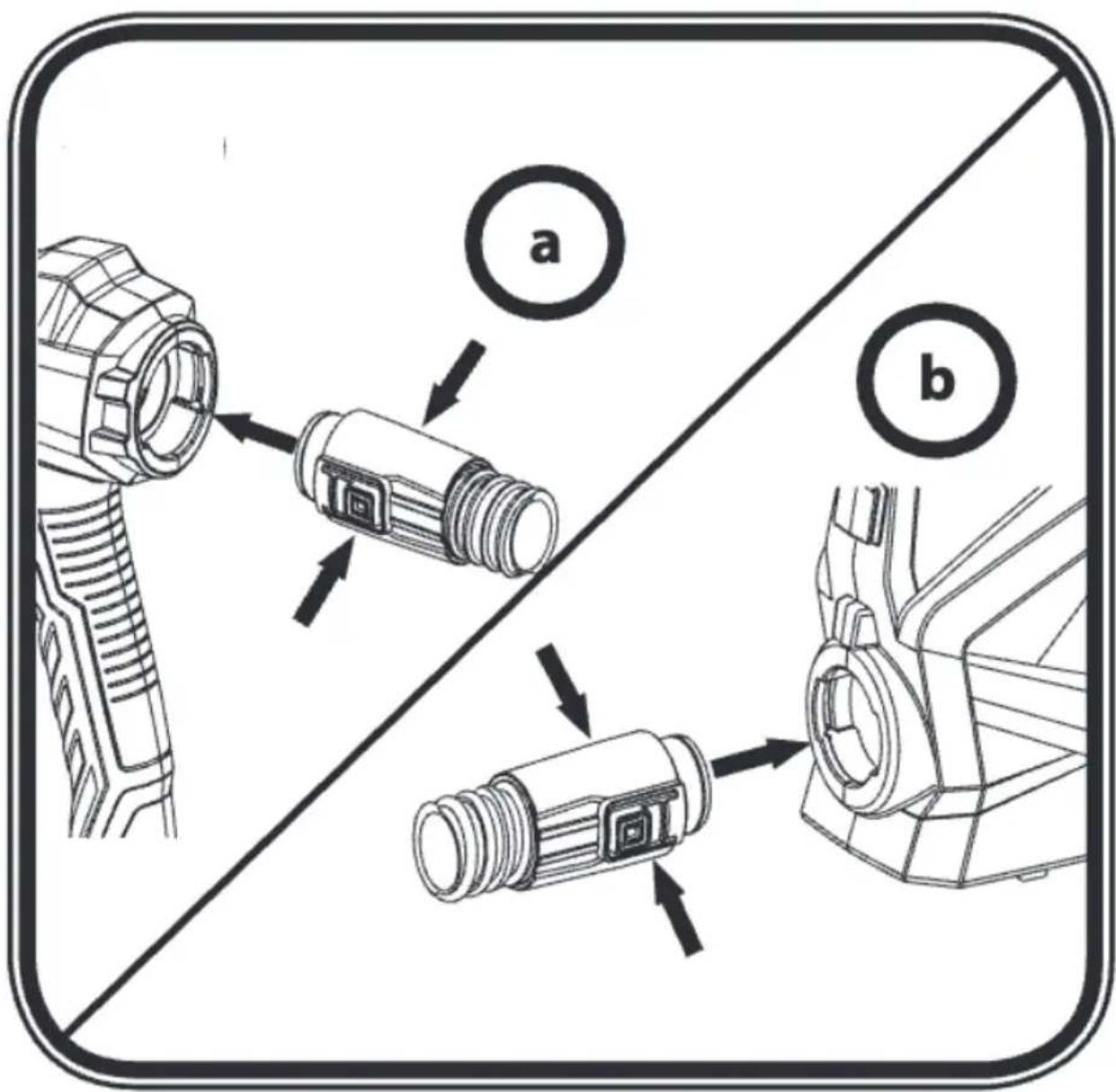
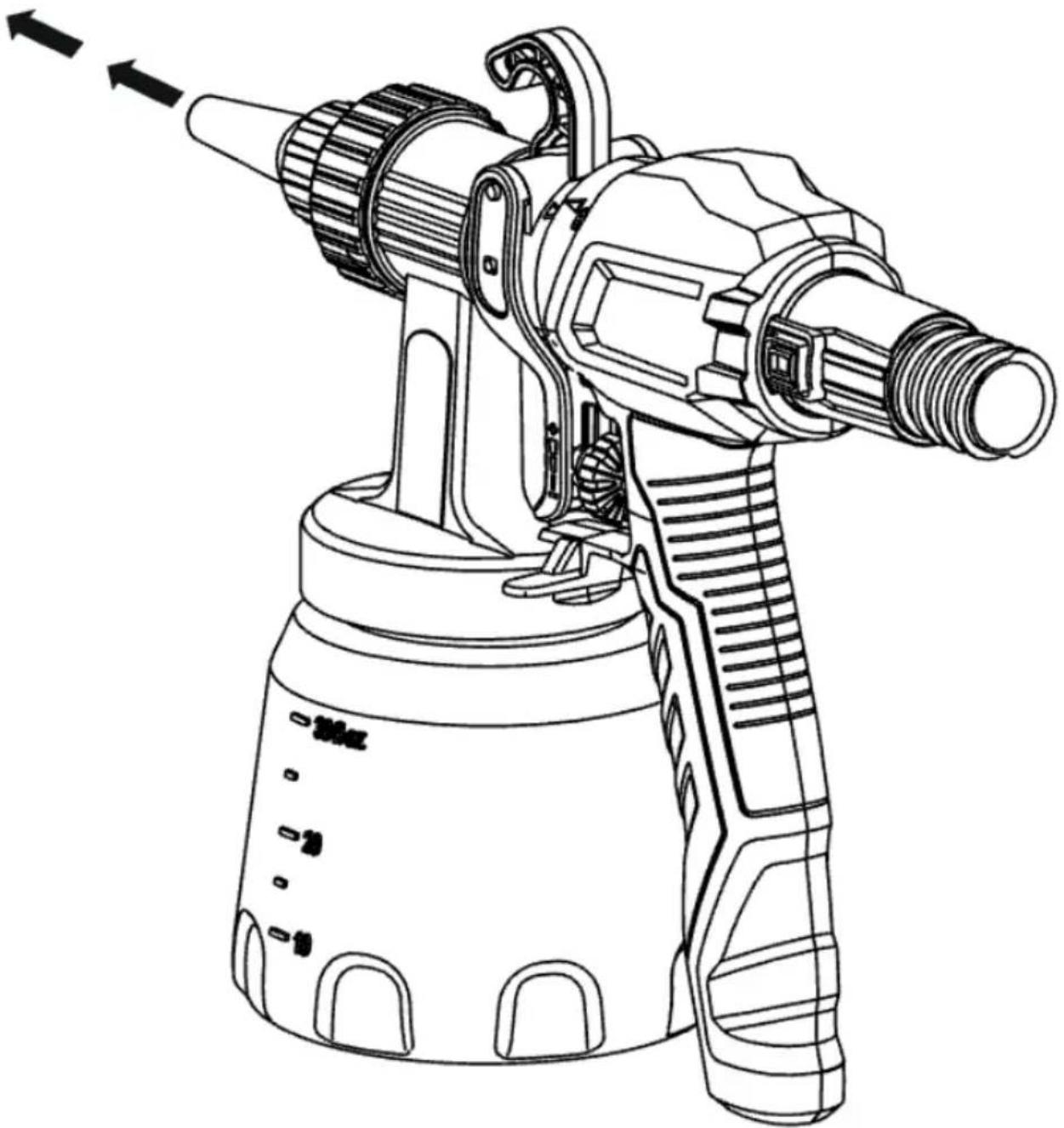
Attach the front assembly to the rear of the spray gun. Fig. 5.
-
Connect the air hose by inserting it firmly into the connection on the unit and into the gun handle. The orientation of the hose is indifferent. Fig. 6 (a+b)
-
Place the main unit only on a level and clean surface. Otherwise, the gun may suck in dust or dirt.
ENGLISH
- Put on the carrying strap and hang it over your shoulder.
- Press the ON/OFF switch on the device to turn it on.
Spray type selection (Fig. 7)
WARNING! Risk of injury! Never pull the trigger while adjusting the air nozzle. Three different spray patterns can be set by turning the air nozzle (Fig. 7, 1).
Tighten the union nut (Fig. 7, 2) so that paint cannot penetrate the unit. Check regularly if the union nut has loosened during operation.
Figure 8 shows the 3 types of spraying available:
- Vertical flat jet: for spraying on horizontal surfaces. Fig. 8A
- Horizontal flat jet: for spraying on vertical surfaces. Fig. 8B
- Circular jet: for spraying in corners, edges and hard-to-reach surfaces. Fig. 8C
To change the shape and width of the spray jet, replace the air cap (1) with the desired one.
Figure 8 shows the 2 possibilities available:
- Wide spray width. Fig. 9A
- Narrow spray width. Fig. 9B
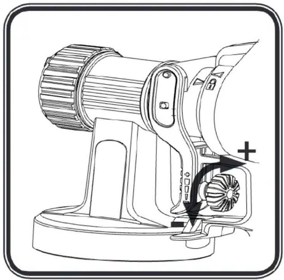
Flow rate adjustment (Fig. 10)
To adjust the volume of material, turn the regulator located on the trigger of the spray gun:
- Turn to the left to reduce the volume of material.
- Turn to the right to increase the volume of material.
For most wall paints, best results are achieved with a medium flow setting.
Spraying technique
- It is advisable to test the spray gun on cardboard or a similar surface to find the correct settings.
- Please note: Start spraying from the edge of the area to be sprayed. Start the spraying motion first, then press the trigger. Avoid stopping or interrupting spraying within the area being sprayed.
- The spraying motion should come from the arm, not the wrist. This ensures that a uniform distance is maintained between the spray gun and the surface during the spraying operation. Select a distance of 20–30 cm, depending on the desired spray pattern width.
o CORRECT spraying: maintain an even distance between the spray gun and the object.
Fig. 11 a
o INCORRECT spraying: uneven spacing will result in uneven paint application. Fig. 11 b
- Move the spray gun uniformly crosswise or up and down, depending on the type of spray pattern selected.
- Uniform spray gun movement results in uniform surface quality.
- If the nozzle and air cap become dirty, clean both parts with water and solvent.
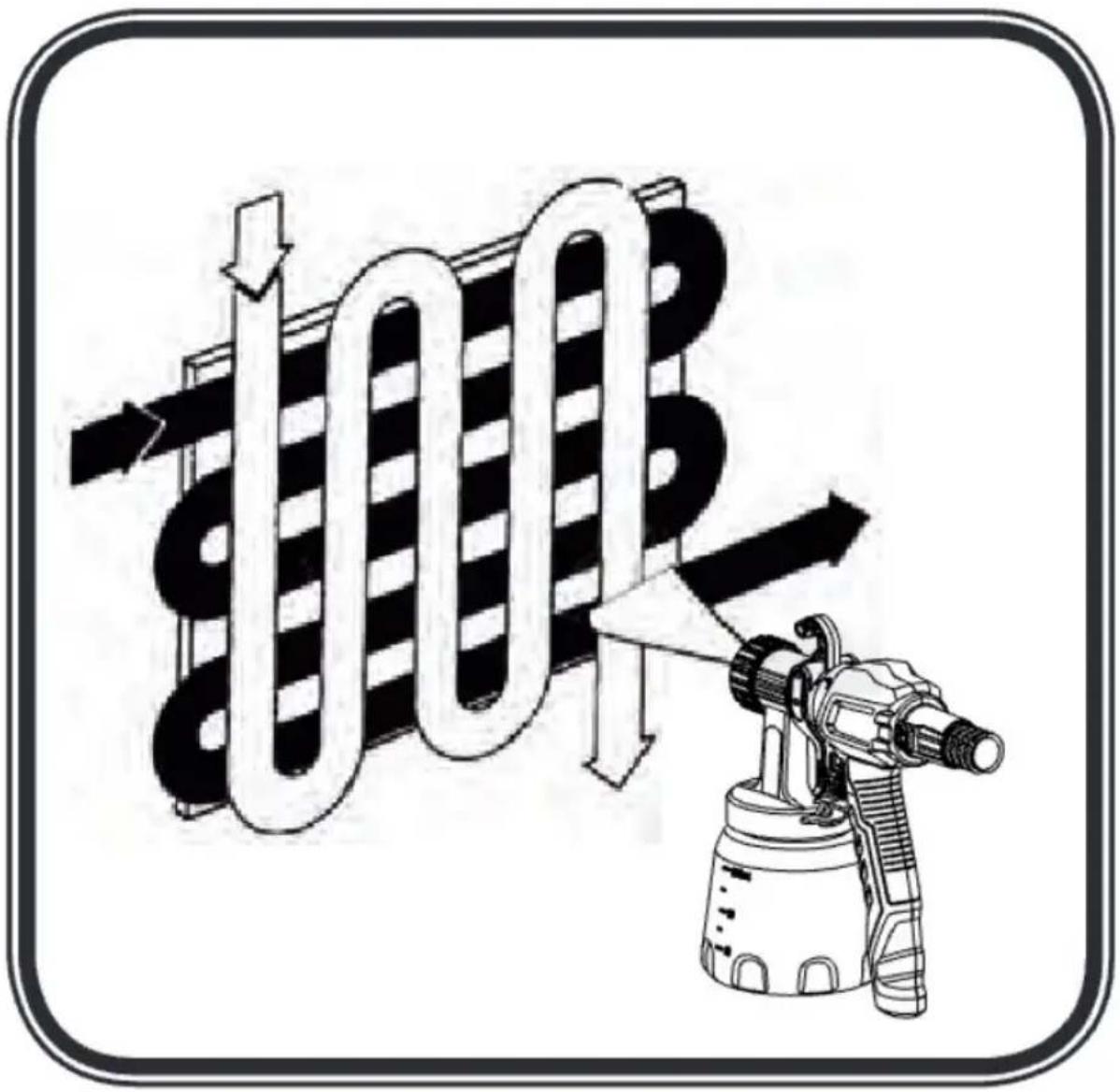
- Useia "cross spray" technique when using low coverage paint or if the surface is very
absorbent. Fig. 12
- Interior wall paints in strong colour tones should be applied at least twice, allowing the first coat of paint to dry first. This will ensure good coverage.
Interruption of operation
- Switch off the machine.
- During longer breaks, ventilate the paint tank by opening it briefly and closing it again.
- Clean the nozzle orifices after a break in operation.
4. CLEANING AND MAINTENANCE
Cleaning
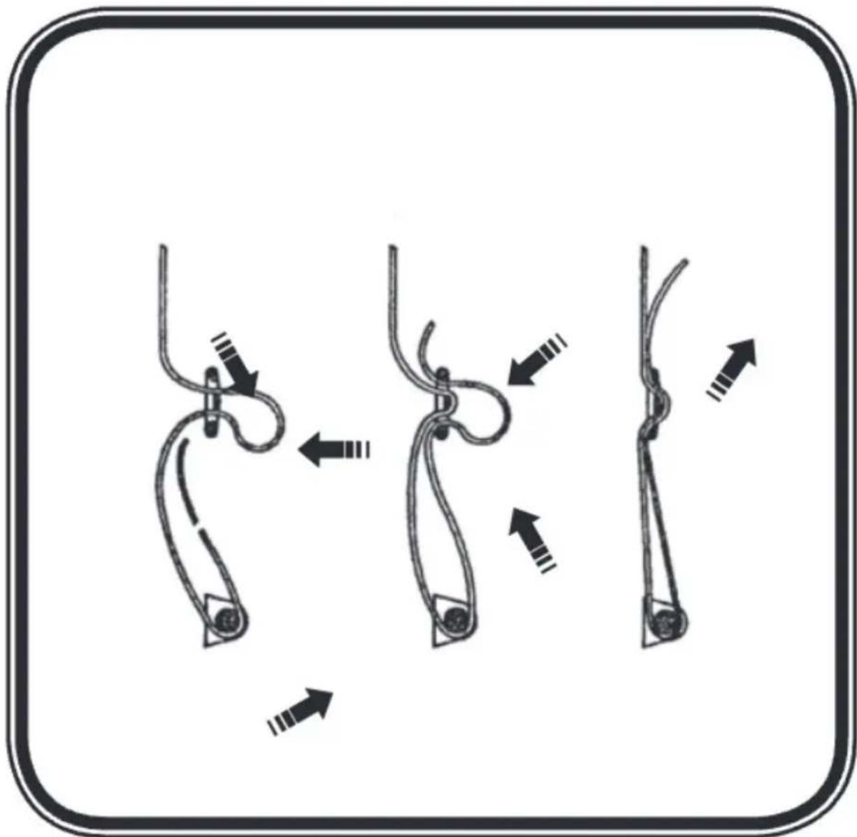
- Switch off the machine.
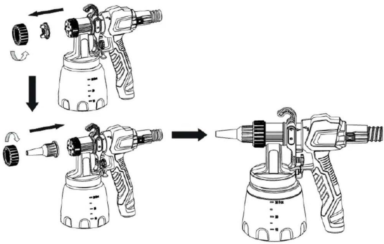
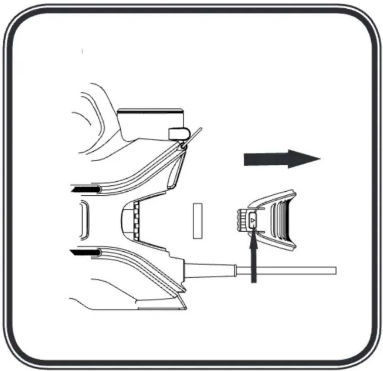
- Disassemble the spray gun. To do this, press the fixing hook down slightly (Fig. 13) and turn the front and rear of the gun in opposite directions.
- Unscrew the paint tank and empty it. Remove the suction pipe together with the gasket from the tank.
- Pre-clean the tank and suction tube with a brush. Clean the vent hole. Fig. 14
We recommend using a common household cleaning brush to clean the tank.
5. Pour water or solvent into the tank and screw it back on. Do not use flammable materials for cleaning.
6. Reassemble the spray gun. Fig. 5.
7. Turn on the gun and spray the water or solvent into a container or a cloth.
8. Repeat the above procedure until the water or solvent coming out of the nozzle is clean.
9. Turn off the spray gun and disassemble it.
10. Unscrew the paint tank and empty it. Remove the suction tube together with the gasket from the tank.
WARNING! Never clean the seals, diaphragm, nozzle or air holes of the spray gun with metal objects. The vent hose and diaphragm are only to a limited extent solvent resistant. Do not soak them in solvent, clean them only with a cloth.
- The spray gun may only be used with an intact valve (Fig. 15.1). If paint gets through the valve clearance (Fig. 15.1), check and clean the valve (see section "Vent valve").
- Turn the locking nut (fig. 16.1) to loosen it and remove it more easily.
- Unscrew the fixing nut (Fig. 16.1). Clean the air nozzle (Fig. 16.2) and the nozzle (Fig. 16.3) with a hand brush, solvent or water.
- Clean the outside of the spray gun and the tank with a cloth dampened with solvent or water.
- Reassemble the parts (see section "Assembly").
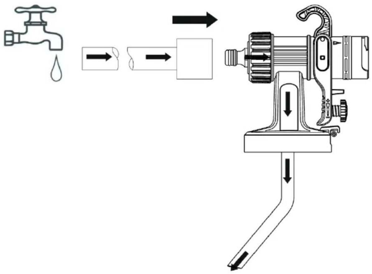
- Another quick method of cleaning the internal duct: connect one end of a hose to the faucet and the other end to the cleaning connector. Open the faucet and rinse the internal line of
ENGLISH
the gun body, as shown in Figure 17.
Assembly
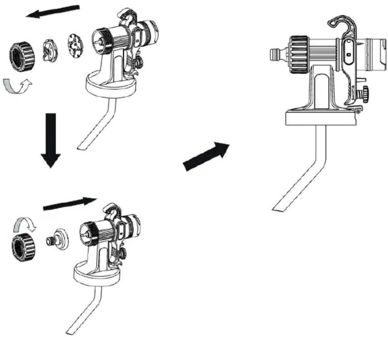
- Screw the union nut (Fig. 18, 1) onto the gun and tighten it.
Make sure that the union nut (Fig. 18, 1) is fully tightened to prevent paint from penetrating the device.
Powder blower connector replacement instructions: Turn the connection counterclockwise, remove the compression nut, remove the spray head, replace the powder blow-off connector and tighten the black compression nut clockwise. Fig. 19
Instructions for powder blowing / inflation: It is used for cleaning narrow gaps (such as door and window seals, computer chassis, etc.), and can also be used for inflating, such as yoga balls, air mattresses, children's toys, etc. Fig. 20
Instructions for the replacement of the cleaning connector: Turn the figure counterclockwise, remove the pressure nut, remove the spray head and nozzle, replace the cleaning connector and tighten the locking nut clockwise. Fig. 21
Cleaning instructions: Connect one end of the water hose to the faucet and the other end to the cleaning connector. Open the faucet to rinse the internal conduit of the gun body. Fig. 17
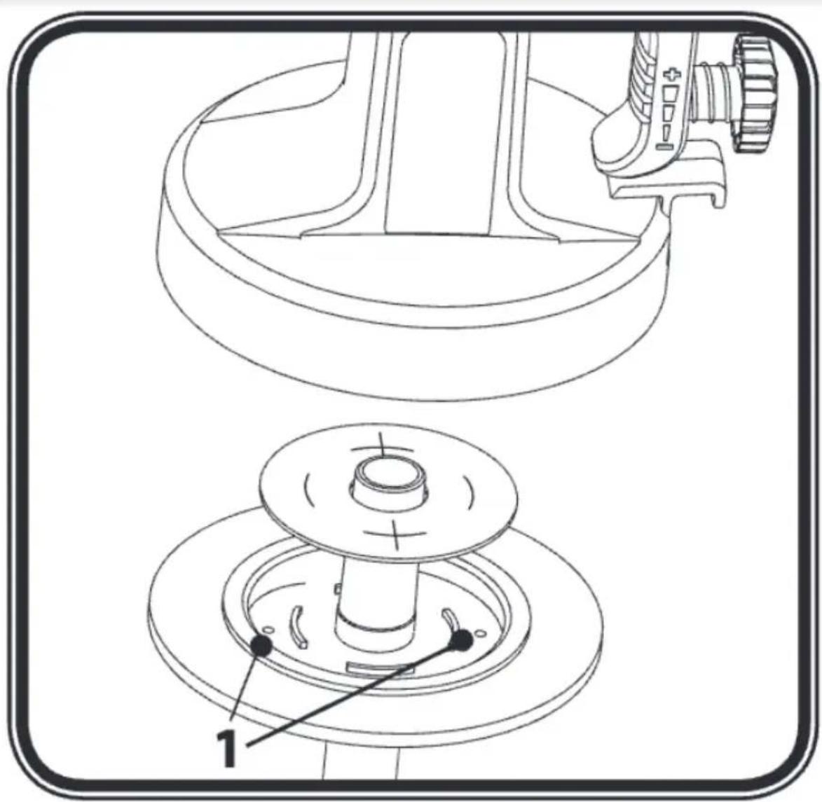
- Place the tank gasket from below onto the suction pipe and slide it over the collar, turning the tank gasket slightly to ensure a secure fit.
- Firmly insert the sealed suction tube into the gun body, making sure it is fully inserted. To facilitate gun assembly, generously apply lubricating grease attached to the O-ring at the front of the gun (see Figure 22, 5).
Service
WARNING! Never use the spray gun without the air filter, as dirt could get inside and affect its operation. Always disconnect the power plug from the mains before changing any parts.
To change the air filter, follow these steps:
- Remove the dirty air filter from the main unit. Fig. 23
- Insert a new air filter into the compartment.
Vent valve
- Remove the suction tube from the lower part of the gun (see figure 24.2) and remove the valve (see figure 24.1) from the suction tube. Clean the part carefully or replace it if damaged.
-
Insert the valve (see figure 24.1) into the top of the suction pipe and place it in the slot.
-
TROUBLESHOOTING
| Problem Possible cause P | Possible solution | |
| No coating material coming out of the nozzle | Clogged nozzle Clean the nozzle | |
| The amount of coating material is insufficient | Increase the amount of coating material | |
| No pressure build-up in the reservoir | Adjust the reservoir | |
| Empty paint tank Refill the paint tank | ||
| Loose suction tube | Correctly insert the suction tube | |
| Suction pipe clogged Clean the suction tube | ||
| Ventilation openings (figs. 14,1 and 15,1) obstructed | Clean the ventilation openings. | |
| Coating material dripping from the nozzle | Material assembly on air nozzle, nozzle or needle | Clean the air nozzle, nozzle or needle. |
| Loose nozzle. Tighten the joint nut | ||
| Nozzle gasket is missing or worn out | Replace the nozzle gasket | |
| Worn nozzle. Replace the nozzle | ||
| Spraying too coarse | The amount of coating material is excessive | Reduce the volume of material |
| Dirty nozzle Clean the nozzle | ||
| Incorrectly mounted air nozzle | Tighten the fastening nut correctly (Fig. 18). | |
| Paint viscosity too high Thin the paint further | ||
| Low reservoir pressure Tighten the reservoir | ||
| Dirty air filter Replace the filter. |
ENGLISH
| Problem Possible cause P | Possible solution | |
| The spray jet is intermittent | The amount of coating material is insufficient | Increase the quantity of coating material |
| Nozzle gasket missing or worn out | Replace the gasket | |
| Dirty air filter Replace the filter. | ||
| Coating material causes "paint drips". | The amount of coating material is excessive | Reduce the volume of material |
| Paint viscosity is too low Thin the paint less | ||
| Overspray of coating material (overspray) | The distance to the object is too great | Reduce the distance |
| The amount of coating material is excessive | Reduce the volume of material | |
| Paint on the ventilation hose | Dirty diaphragm Clean the diaphragm | |
| Defective diaphragm Replace diaphragm | ||
| Poor wall coverage capacity | Spray material is too cold | Spray materials should be stored at room temperature. |
| Highly absorbent surface or paint with low covering capacity | Perform the cross-spraying technique (See figure 12) | |
| The distance to the object is too great | Approach the object | |
6. TECHNICAL SPECIFICATIONS
Product reference: EU01_102254
Product: PerfectPaint 800 EasyGo
Motor power: 800 W
Frequency: 50 Hz
Voltage: 230 V
Container capacity: 800 ml
Max. Viscosity:120 DIN/S
Maximum flow: 1100 mL/min
Technical specifications may change without prior notification to improve product quality.
Made in China | Designed in Spain
7. DISPOSAL OF OLD ELECTRICAL AND ELECTRONIC APPLIANCES

This symbol indicates that, according to the applicable regulations, the product and/or batteries must be disposed of separately from household waste. When this product reaches the end of its shelf life, you should dispose of the cells/batteries/accumulators and take them to a collection point designated by the local authorities.
For detailed information on how to properly dispose of electrical and electronic appliances and/or batteries, consumers should contact their local authorities.
Compliance with the above guidelines will help protecting the environment.
8. TECHNICAL SUPPORT AND WARRANTY
Cecotec shall be liable to the end user or consumer for any lack of conformity that exists at the time of delivery of the product under the terms, conditions and deadlines established by the applicable regulations.
Repairs should be carried out by qualified personnel.
If at any moment you detect any problem with your product or have any doubt, do not hesitate to contact the official Cecotec Technical Support Service at +34 963 210 728.
9. COPYRIGHT
The intellectual property rights over the texts in this manual belong to CECOTEC INNOVACIONES, S.L. All rights reserved. The contents of this publication may not, in whole or in part, be reproduced, stored in a retrieval system, transmitted, or distributed by any means (electronic, mechanical, photocopying, recording or similar) without the prior authorization of CECOTEC INNOVACIONES, S.L.
ENGLISH
10. DECLARATION OF CONFORMITY
MANUFACTURER: CECOTEC INNOVACIONES S.L
ADDRESS: Av. Reyes Católicos, 60, 46910, Alfafar, Valencia (Spain)
DESCRIPTION: Spray gun
PRODUCT IDENTIFICATION: PerfectPaint 800 EasyGo Spray gun
FUNCTION: Paint spray gun
MODEL: EU01_102254
It certifies the appliance described has been designed, manufactured and tested and complies with all applicable provisions.
EU DIRECTIVES IMPLEMENTED:
- Directive 2006/42/CE on machinery.
- Directive 2014/30/EU on the harmonisation of the laws of the Member States relating to electromagnetic compatibility.
- Directive 2011/65/EU and delegated directive (EU) 2015/863 on the restriction of the use of certain hazardous substances in electrical and electronic equipment.
APPLICABLE HARMONISED NORMS:
- EN 62841-1:2015 +A11:2022
- EN 50580:2012 +A1:2013
- EN IEC 55014-1:2021
- EN IEC 55014-2:2021
- EN IEC 61000-3-2:2019 +A1:2019
- EN 61000-3-3:2013 +A1:2019 +A2:2021
1. PIÈCES ET COMPOSANTS
Img. 1
GYÁRTÓ: CECOTEC INNOVATIONS S.L
CÍM: Av. Reyes Católicos, 60, 46910, Alfafar, Valencia (Spanyolország)
Fig./Img./Abb./Afb./Rys.1
natural_image
Diagram of a funnel pouring liquid into a conical flask (no text or symbols)Fig./Img./Abb./Afb./Rys.2
flowchart
graph TD
    A["Initial State"] --> B["Step 1"]
    B --> C["Step 2"]
    C --> D["Step 3"]
Fig./Img./Abb./Afb./Rys. 3
natural_image
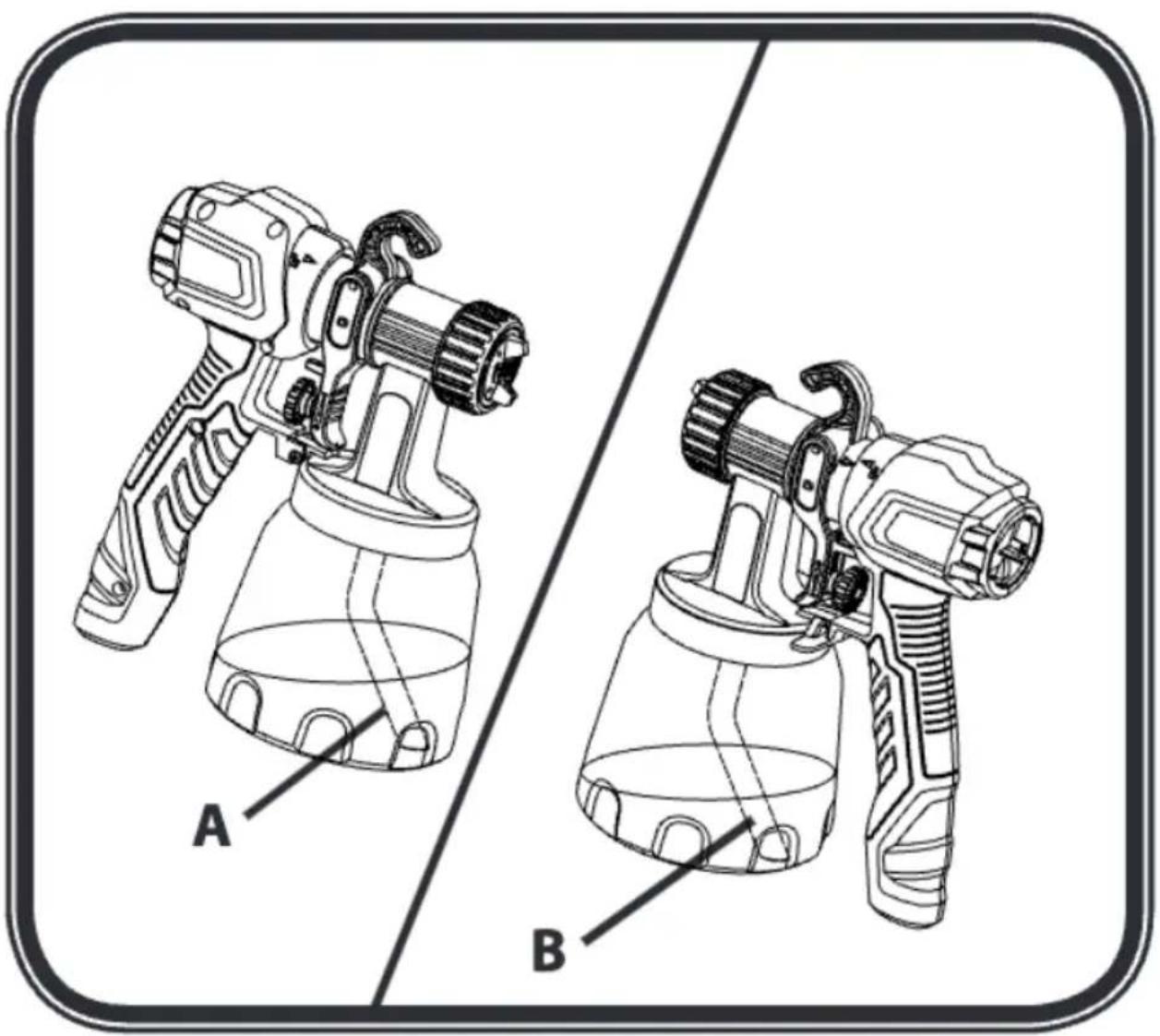
Technical line drawing of two spray gun holders (A and B) with no visible text or symbolsFig./Img./Abb./Afb./Rys. 4
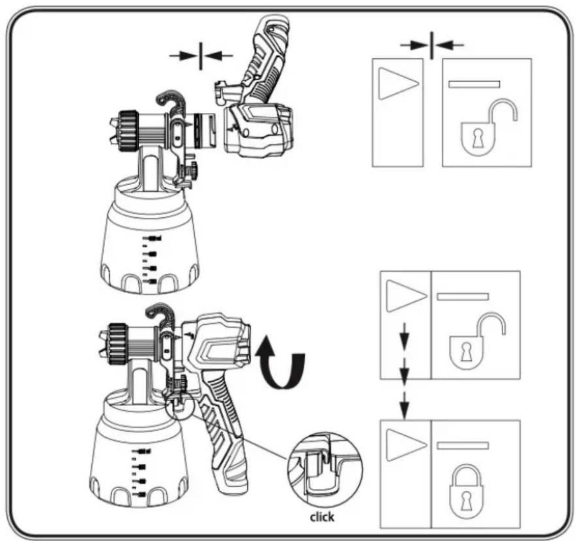
Fig./Img./Abb./Afb./Rys.5
flowchart
graph TD
    A["Component a"] --> B["Arrow to a component"]
    C["Component b"] --> D["Arrow to a component"]
    B --> E["Arrow to a component"]
    D --> F["Arrow to a component"]
Fig./Img./Abb./Afb./Rys.6
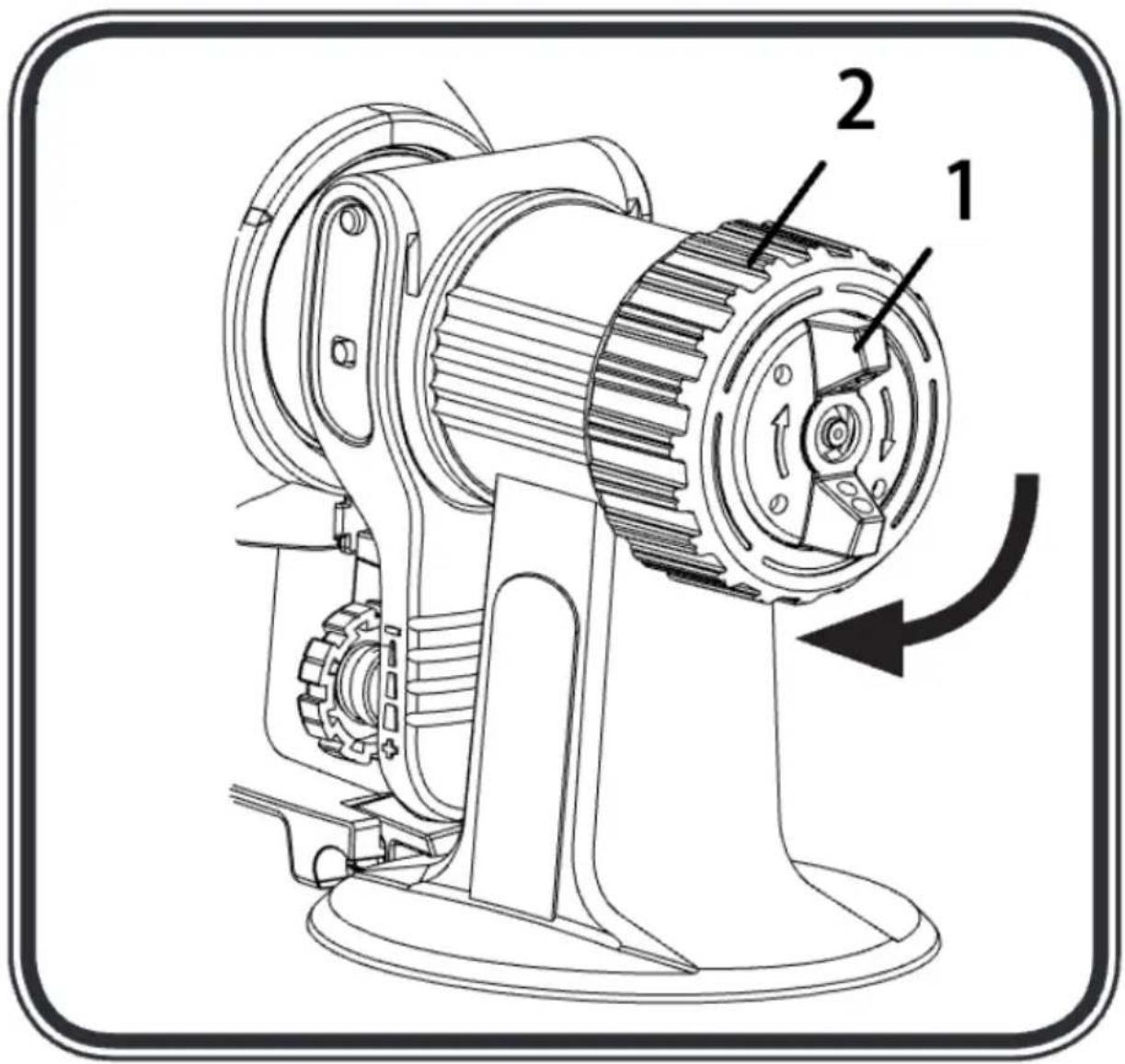
Fig./Img./Abb./Afb./Rys.7
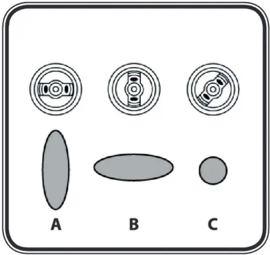
Fig./Img./Abb./Afb./Rys. 8
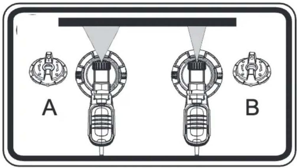
Fig./Img./Abb./Afb./Rys. 9
natural_image
Technical line drawing of a mechanical device with no visible text or symbolsFig./Img./Abb./Afb./Rys.10

Fig./Img./Abb./Afb./Rys.11
natural_image
Illustration of a spray gun operating with a coiled tube, showing airflow direction (no text or symbols)Fig./Img./Abb./Afb./Rys.12

Fig./Img./Abb./Afb./Rys.13
natural_image
Technical line drawing of a mechanical assembly with three views: top view, side view, and bottom view (no text or symbols)Fig./Img./Abb./Afb./Rys.14
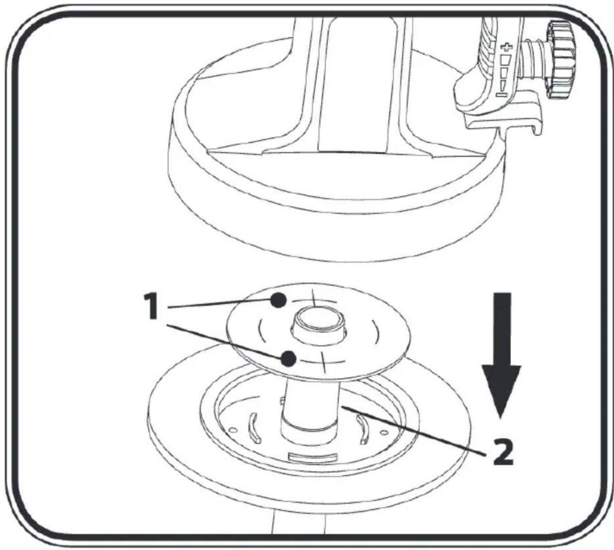
Fig./Img./Abb./Afb./Rys.15
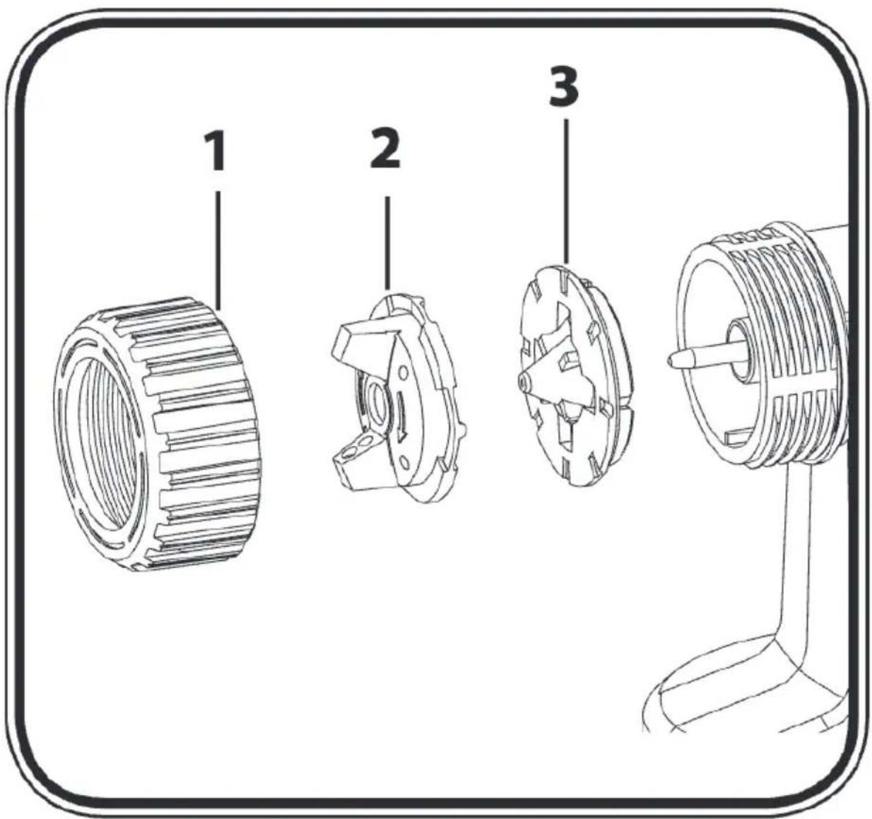
Fig./Img./Abb./Afb./Rys.16
flowchart
graph LR
    A["Water Drop"] --> B["Pump Open"]
    B --> C["Pipe Opening"]
    C --> D["Tool Mount"]
    D --> E["Downward Arrow"]
    style A fill:#f9f,stroke:#333
    style E fill:#bbf,stroke:#333
Fig./Img./Abb./Afb./Rys.17
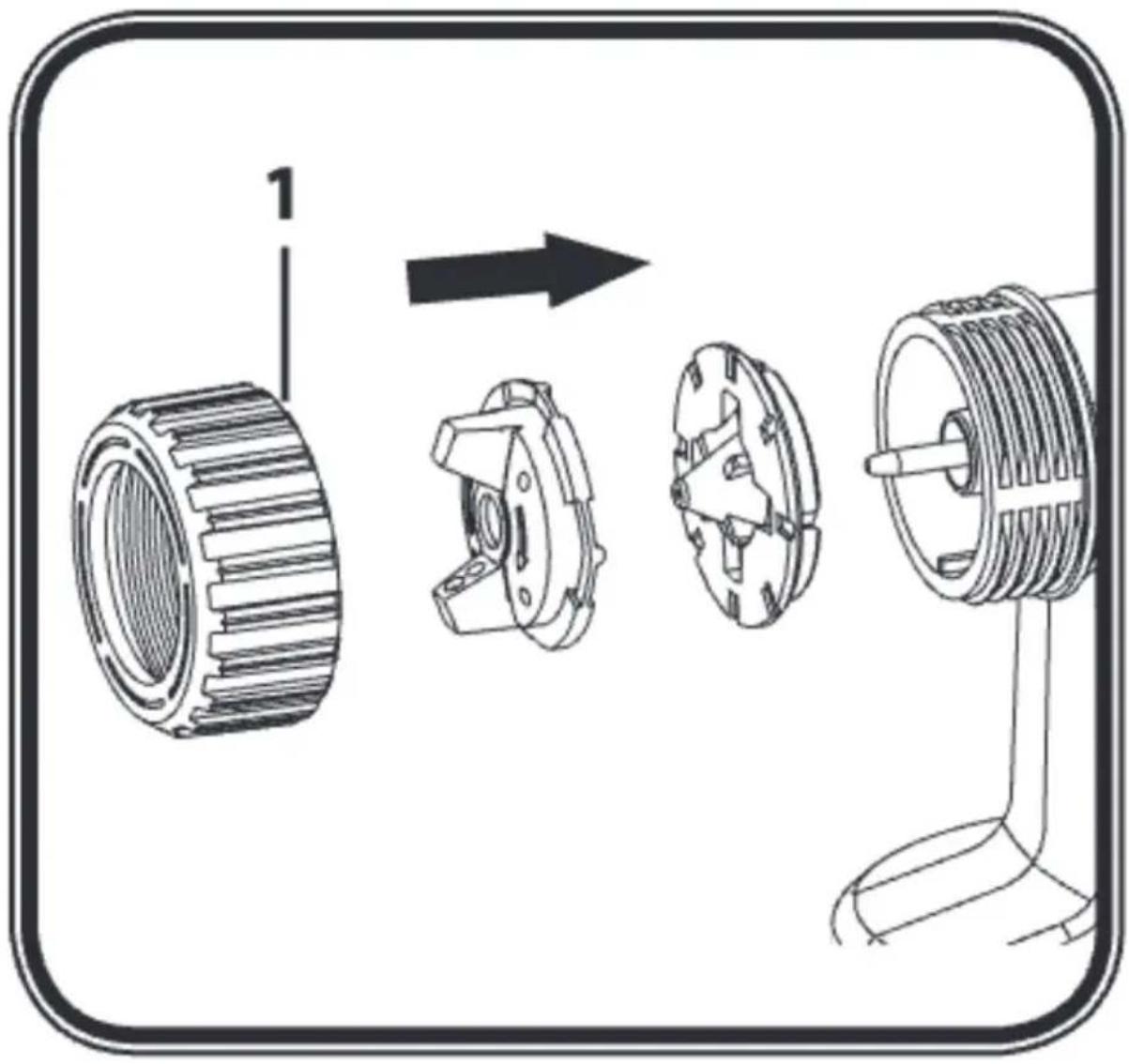
Fig./Img./Abb./Afb./Rys.18
flowchart
graph TD
    A["Initial Gas Gun"] --> B{Reaction Step}
    B -->|Down Roll| C["Assembly Tool"]
    B -->|Up Roll| D["Final Assembly Tool"]
    D --> E["Final Output"]
Fig./Img./Abb./Afb./Rys.19
natural_image
Line drawing of a spray gun with nozzle and handle (no text or symbols)Fig./Img./Abb./Afb./Rys.20
flowchart
graph TD
    A["Disassembly"] --> B["Lossing"]
    B --> C["Molding"]
    C --> D["Mounting"]
    D --> E["Stacking"]
    style A fill:#f9f,stroke:#333
    style B fill:#ccf,stroke:#333
    style C fill:#cfc,stroke:#333
    style D fill:#fcc,stroke:#333
Fig./Img./Abb./Afb./Rys. 21
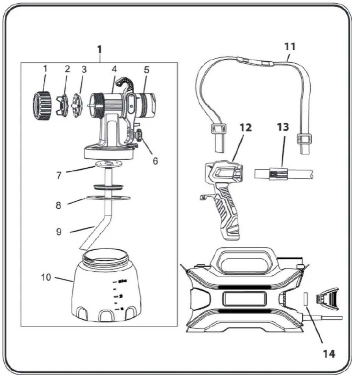
Fig./Img./Abb./Afb./Rys.22
natural_image
Technical diagram showing mechanical assembly steps with no visible text or symbolsFig./Img./Abb./Afb./Rys.23
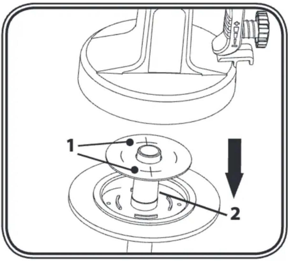
Fig./Img./Abb./Afb./Rys. 24
www.cecotec.es