
PBK 4 C4 - Multitools PARKSIDE - Free user manual and instructions
Find the device manual for free PBK 4 C4 PARKSIDE in PDF.

| Product type | Petrol multifunction tool |
| Brand | Parkside |
| Model | PBK 4 C4 |
| Engine | 2-stroke, 52 cc, 1.4 kW (1.9 HP) |
| Fuel | Petrol-oil mixture 40:1 (ROZ 95/98) |
| Fuel tank capacity | 1.2 L |
| Chain oil tank capacity | 140 ml |
| Weight power head (empty) | 6 kg |
| Weight grass trimmer | 1.7 kg |
| Weight brush cutter | 1.57 kg |
| Weight hedge trimmer | 2.2 kg |
| Weight pole pruner | 1.7 kg |
| Total length hedge trimmer | 2.38 m |
| Total length pole pruner | 2.13 m |
| Cutting diameter grass trimmer | 430 mm |
| Cutting diameter brush cutter | 255 mm |
| Cutting length hedge trimmer | 480 mm |
| Cutting length pole pruner | 290 mm (12" guide bar) |
| Functions | Grass trimming, brush cutting, hedge trimming, pole pruning |
| Safety | Protective guard, command lock, emergency stop, kickback protection |
| Maintenance | Air filter cleaning, spark plug, chain lubrication, transmission greasing |
| Spare parts supplied | Spool of line, chain, guide bar, blade, guard, etc. |
| Guaranteed sound power level | 116 dB(A) |
Frequently Asked Questions - PBK 4 C4 PARKSIDE
User questions about PBK 4 C4 PARKSIDE
0 question about this device. Answer the ones you know or ask your own.
Ask a new question about this device
Download the instructions for your Multitools in PDF format for free! Find your manual PBK 4 C4 - PARKSIDE and take your electronic device back in hand. On this page are published all the documents necessary for the use of your device. PBK 4 C4 by PARKSIDE.
USER MANUAL PBK 4 C4 PARKSIDE
natural_image
Technical line drawing of mechanical components including a robotic arm, chain linkers, and spray bottle (no text or labels)
PETROL MULTI TOOL PBK 4 C4
BENZIN-KOMBIGERÄT PBK 4 C4
OUTIL MODULABLE À ESSENCE PBK 4 C4

Petrol multi tool
Operating and Safety Instructions
Translation of the original operating instructions
WARNING: READ CAREFULLY BEFORE USE AND STORE IN A SAFE PLACE FOR FUTURE REFERENCE.

WAARSCHUWING: VOOR GEBRUIK ZORGVULDIG
DOORLEZEN EN GOED BEWAREN VOOR LATER GEBRUIK.

Before reading, unfold the page with the illustrations and then familiarise yourself with all the functions of the product.
DE AT CH
GB / IE / NI / CY / MT Operating and Safety Instructions Page 1
natural_image
Illustration of a person adjusting a belt buckle (no text or symbols)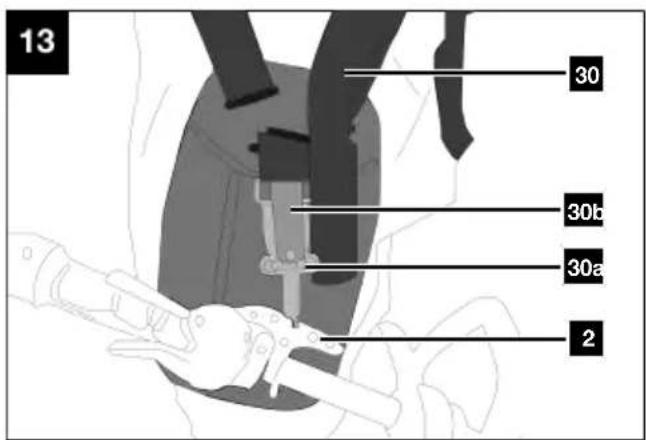
natural_image
Line drawing of a tank with visible exhaust plume and numbered label (16), no text or symbols present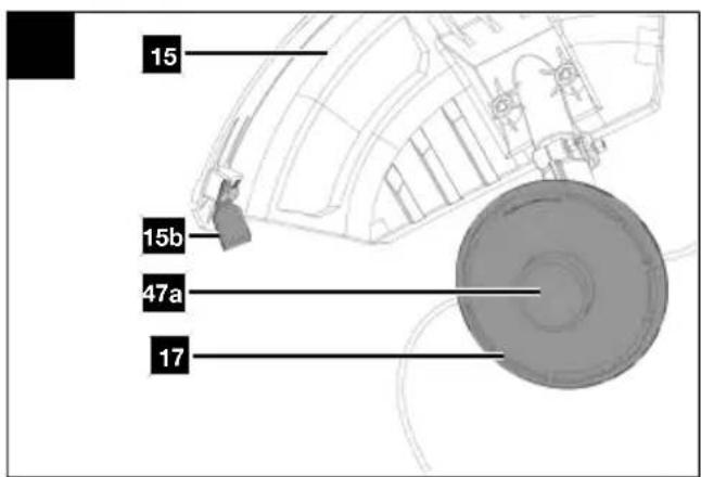

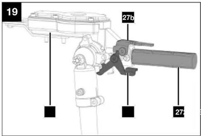
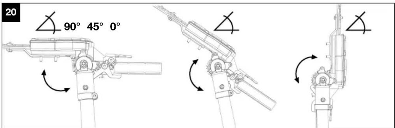
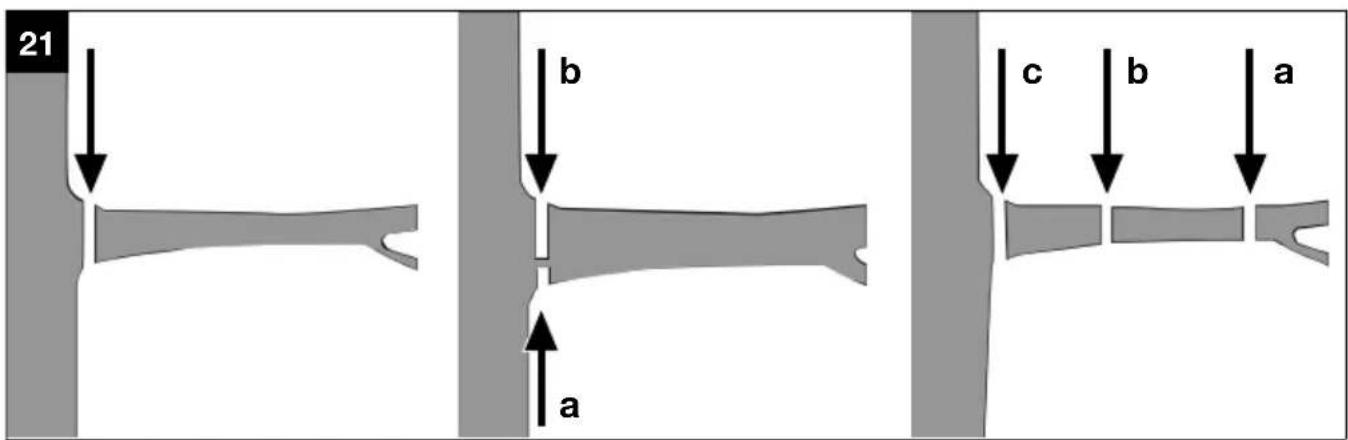
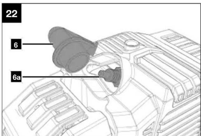
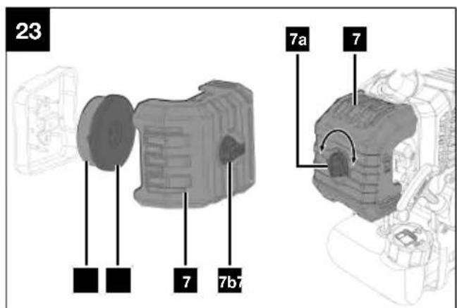
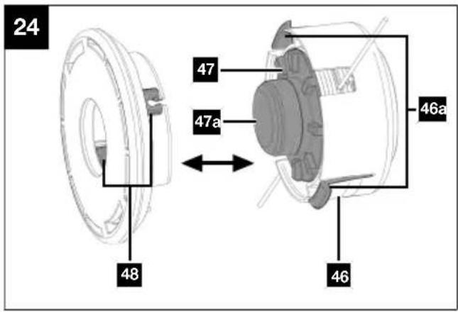
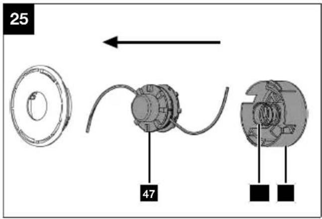
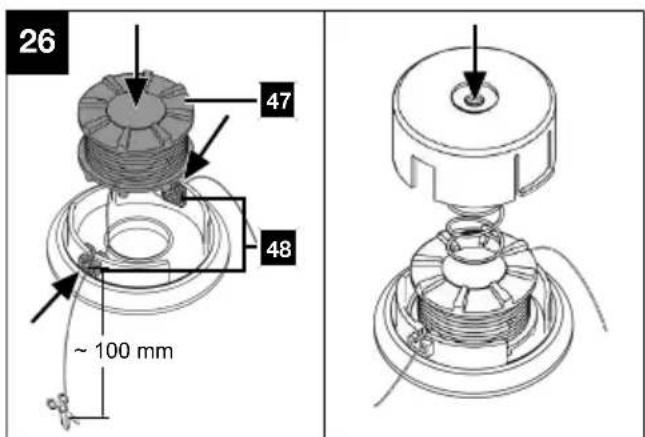
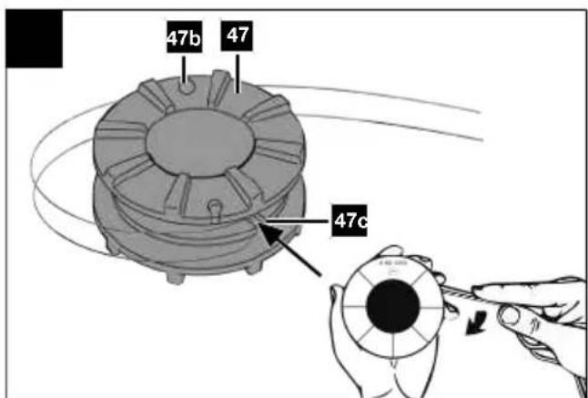
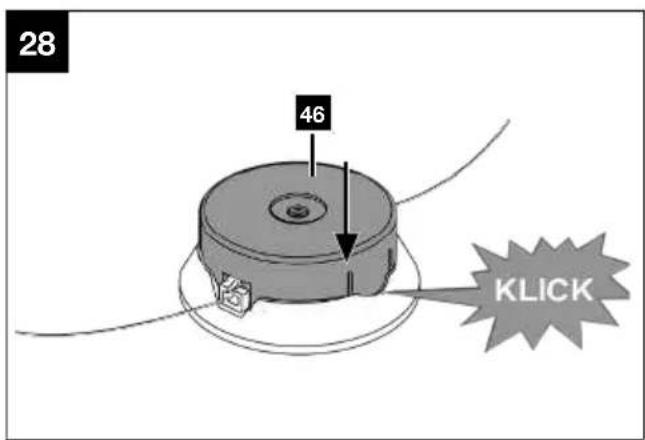
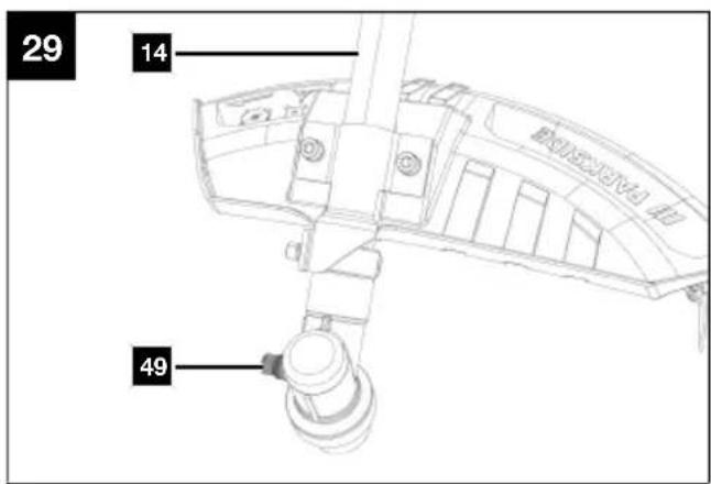
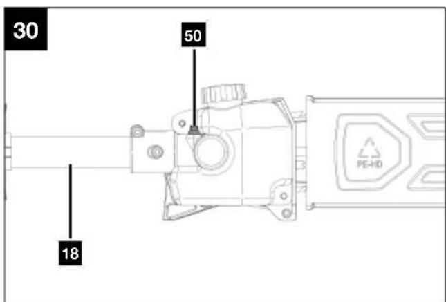
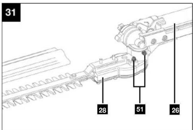
Table of contents
1 Explanation of the symbols on the product.... 2
2 Introduction.... 4
3 Product description (Fig. 1-31) 4
4 Scope of delivery (Fig. 1-31) 5
5 Proper use.... 5
6 Safety instructions 6
7 Technical data.... 10
8 Unpacking.... 11
9 Assembly.... 12
10 Before commissioning 14
11 Operation.... 17
12 Working instructions.... 19
13 Cleaning 21
14 Maintenance 22
15 Storage.... 27
16 Transport.... 28
17 Repair and ordering spare parts 28
18 Disposal and recycling.... 28
19 Troubleshooting.... 29
20 EU Declaration of Conformity 30
21 Warranty certificate.... 31
22 Exploded view.... 203
1 Explanation of the symbols on the product
Symbols are used in this manual to draw your attention to potential hazards. The safety symbols and the accompanying explanations must be fully understood. The warnings themselves will not rectify a hazard and cannot replace proper accident prevention measures.
 | Attention! Failure to observe the safety signs and warning information affixed to the product and failure to observe the safety and operating manual can result in serious injury or even death. |  | Always switch off the engine before refuelling. |
 | Before commissioning, read and observe the operating manual and safety instructions! |  | Important. The exhaust gases are toxic. Do not operate the engine in areas that are not ventilated. |
 | Before commissioning, read and observe the operating manual and safety instructions! |  | Remove the spark plug connector prior to all maintenance work. |
 | Wear safety goggles. Cutting length |  | |
 | Wear hearing protection. Chain lubrication |  | |
 | Always wear a safety helmet! Cutter be |  | |
 | Wear safety gloves! |  | Direction of rotation of the thread coil. |
 | Wear sturdy footwear! Thread coil. |  | |
 | It is important to wear protective clothing for hands, forearms, legs and feet. |  | Direction of rotation of grass trimmer. |
 | Do not expose the product to rain. The product may only be stationed, stored and operated in dry ambient conditions. |  | Cutting blade. |
 | Attention! Risk of injury from running blades. |  | Cutting blade diameter. |
 | Make sure that other persons maintain a sufficient safety distance.Keep unauthorised people away from the product.Hurled objects and rotating parts can cause severe injuries. | Fuel/oil mixture 40:1 | |
| Make sure that other persons maintain a sufficient safety distance. |  | Tank contents. Fuel: ROZ 95 / ROZ 98 | |
| Keep your distance from other people and electrical lines. |  | Tank contents | |
 | Watch out for falling material. |  | Mixing ratio of fuel to 2-stroke engine oil 40:1 |
 | Do not use a saw blade. Press the fuel pun |  er" 10x. er" 10x. | |
 | Keep your feet away from the tool attachment. |  | Press the fuel pump (primer) 10 x. |
 | Material removal direction Turn the choke I |  | |
 | Naked flames or smoking near the device is strictly prohibited! |  | Pull the pull starter. |
 | The motor becomes very hot during operation, do not touch! |  | Guaranteed sound power level of the product. |
 | Warning! Risk of kick-back.Beware of the kick-back of the product and avoid making contact with the rail tip. |  | The product complies with the applicable European directives. |
 | Important. The exhaust gases are toxic. Do not operate the engine in areas that are not ventilated. | ||
2 Introduction
Manufacturer:
Scheppach GmbH
Günzburger Straße 69
D-89335 Ichenhausen
Dear Customer
We hope your new product brings you much enjoyment and success.
Note:
In accordance with the applicable product liability laws, the manufacturer of this product assumes no liability for damage to the product or caused by the product arising from:
- Improper handling
• Non-compliance with the operating manual
• Repairs carried out by third parties, unauthorised specialists - Installing and replacing non-original spare parts
- Improper use
Note:
The operating manual is part of this product.
It includes important instructions for the safe, proper and economic operation of the product, for avoiding danger, for minimising repair costs and downtimes and for increasing the reliability and extending the service life of the product. In addition to the safety instructions in this operating manual, you must also observe the regulations applicable to the operation of the product in your country.
Familiarise yourself with all operating and safety instructions before using the product. Only operate the product as described and for the specified areas of application. Keep the operating manual in a good place and hand over all documents when passing the product on to third parties.
3 Product description (Fig. 1-31)
- Front handle
1a. Hoop guard
1b. Rubber ring
1c. Wing nut
1d. Retaining clip
1e. Clamping pin
1f. Threaded pins - Lifting eye
- On/off switch
- Switch lock
- Rear handle
- Spark plug connector
6a. Spark plug - Air filter cover
7a. Screw
7b. Cover
7c. Air filter
8. Pull starter
9. Fuel filler cap
10. Fuel tank
11. Throttle
12. Tubular shaft
12a. Protective plug
13. Star grip (tubular shaft)
Brush cutter/grass trimmer
- Front tubular shaft
14a. Locking pin
14b. Protective cap
14c. Flange
14d. Receptacle spindle
- Protective cover
15a. Allen screw M6
15b. Thread cutter
15c. Extension piece
- Cutting blade
16a. Transport protection
16b. Spring washer
16c. Cover
16d. M10 nut
- Coil capsule
Pole-mounted pruner
- Front tubular shaft
18a. Locking pin
18b. Protective cap
- Chain cover
19a. Fixing nut
-
Chainsaw guide bar (guide rail)
-
Saw chain
-
Guide bar and chain guard
-
Oil tank
23a. Oil level indicator
- Tubular shaft extension
24a. Locking pin
24b. Protective cap
24c. Protective plug
- Star grip
Hedge trimmer
- Front tubular shaft
26a. Locking pin
26b. Protective cap
- Handle
27a. Unlocking lever (bottom)
27b. Unlocking lever (top)
-
Cutter bar
-
Blade guard
Accessories/Tools/Miscellaneous
- Carrying strap
30a. Carabiner hook
30b. Safety tab
-
Oil-petrol mixing bottle
-
Replacement thread
-
Tool bag
-
Installation spanner (AF 19/21 mm, slotted screwdriver)
-
Allen key, 5 mm
-
Funnel
-
Chain oil
-
Safety goggles
Pole-mounted pruner
-
Chain wheel
-
Chain tensioning bolt
-
Guide pin
-
Chain tensioning screw
-
Adjusting screw (saw chain lubrication)
Accessories/Tools/Miscellaneous
-
Fuel pump "primer"
-
Choke
Brush cutter/grass trimmer
- Cover
46a. Unlocking
46b. Pressure spring
- Thread coil
47a. Trigger
47b. Notch
47c. Notches (centre of thread coil)
- Thread outlet eyelets
Brush cutter/grass trimmer
- Maintenance screw
Pole-mounted pruner
- Maintenance screw
Hedge trimmer
- Maintenance screw
4 Scope of delivery (Fig. 1-31)
Item Quanti- Designation
ty
- 1 x Front handle
1a. 1 x Hoop guard
1b. 1 x Rubber ring
1c. 1 x Wing nut
1d. 1 x Retaining clip
-
1 x Front tubular shaft (brush cutter/grass trimmer)
-
1 x Protective cover
15a. 2 x Allen screw M6
- 1 x Cutting blade
16a. 1 x Transport protection (cutting blade)
16b. 1 x Spring washer
16c. 1 x Cover
16d. 1 x M10 nut
-
1 x Coil capsule
-
1 x Front tubular shaft (pole-mounted pruner)
-
1 x Chainsaw guide bar (guide rail)
-
1 x Saw chain
-
1 x Guide bar and chain guard
-
1 x Tubular shaft extension
-
1 x Front tubular shaft (hedge trimmer)
-
1 x Blade guard (hedge trimmer)
-
1 x Carrying strap
-
1 x Oil-petrol mixing bottle
-
1 x Replacement thread
-
1 x Tool bag
-
1 x Installation spanner (AF 19/21 mm, slotted screwdriver)
-
1 x Allen key, 5 mm
-
1 x Funnel
-
1 x Chain oil
-
1 x Safety goggles
1 x Petrol multipurpose garden tool
1 x Operating manual
5 Proper use
The product may only be fitted to the motor head supplied.
Brush cutter:
The brush cutter (using the cutting knife) is suitable for cutting shrubs, strong weed and undergrowth.
Grass trimmer:
The grass trimmer (using thread coil with trimming line) is suitable for cutting lawns, grass areas and light weed.
Hedge trimmer:
This hedge trimmer is intended for cutting hedges, bushes and shrubs.
Pole-mounted pruner (cordless chainsaw with telescopic handle):
The pole-mounted pruner is intended for branch removal work. It is not suitable for extensive sawing work and felling trees as well as sawing materials other than wood.
The product may only be used in the intended manner. Any use beyond this is improper. The user, not the manufacturer, is responsible for damages or injuries of any type resulting from this.
An element of the intended use is also the observance of the safety instructions, as well as the assembly instructions and operating information in the operating manual.
Persons who operate and maintain the product must be familiar with the manual and must be informed about potential dangers.
The liability of the manufacturer and resulting damages are excluded in the event of modifications of the product.
The product may only be operated with original parts and original accessories from the manufacturer.
The safety, operating and maintenance specifications of the manufacturer, as well as the dimensions specified in the technical data, must be observed.
Please note that our products were not designed with the intention of use for commercial or industrial purposes. We assume no guarantee if the product is used in commercial or industrial applications, or for equivalent work.
Explanation of the signal words in the operating manual

DANGER
Signal word to indicate an imminently hazardous situation which, if not avoided, will result in death or serious injury.

WARNING
Signal word to indicate a potentially hazardous situation which, if not avoided, could result in death or serious injury.

CAUTION
Signal word to indicate a potentially hazardous situation which, if not avoided, could result in minor or moderate injury.
ATTENTION
Signal word to indicate a potentially hazardous situation which, if not avoided, could result in product or property damage.
6 Safety instructions
Keep all safety information and instructions for future reference!

WARNING
Read all safety warnings, instructions, illustrations and specifications provided with this product.
Failure to observe the following instructions can result in serious injuries.

WARNING
Before you start working with the product, familiarise yourself well with all the control parts.
- Practice using the product and have an experienced user or specialist explain its function, how it works and the techniques involved.
- Ensure that the product can be stopped immediately in the event of an emergency.
- Improper use may cause severe injuries.
- In the event of an accident or a fault during operation, switch the product off immediately. Treat injuries properly or consult a doctor.
6.1 Safety instructions for brush cutters and grass trimmers

WARNING
Stay alert, watch what you are doing and use common sense when operating the tool.
Do not use any tool while you are tired or under the influence of drugs, alcohol or medication.
A moment of carelessness when using the tool can result in serious injuries.

WARNING
It is necessary to keep third parties away. People should keep a safety distance of at least 15 metres from the work area.
a) Never use the Product while standing on a ladder.
b) Always keep the product in good operating condition.
c) Do not lean too far forwards when using the product. Always make sure you have a firm footing and keep your balance at all times. Use the carrying strap in the scope of delivery to distribute the weight evenly across the body.
d) Take regular breaks and change your working position regularly.
e) It is necessary to conduct daily inspections before use and after dropping or other impacts to determine any significant damage or defects.
f) National regulations may restrict the use of the product.
g) Always wear sturdy footwear and long trousers when operating the product. Do not operate the product barefoot or in open sandals. Avoid wearing loose-fitting clothing or clothing with hanging strings or ties.
h) Wear personal protective equipment when using the product:
Hearing protection, eye protection (visor or goggles), head protection and cut-resistant work clothing.
i) Only work in daylight or with good, artificial lighting.
j) Never operate the product with defective Protective devices or without safety devices.
k) Do not put your hands or feet in the area of the rotating tool before or after switching on.
I) If a foreign object has been hit, switch off the product immediately and disconnect the spark plug connector from the spark plug. Inspect the product for damage and perform the required repairs before starting again and working with the product. If the product begins to experience exceptionally strong vibrations, switch it off immediately and check it.
m) Check the covers and protective devices for damage and correct seating. Replace them if necessary.
n) Check the product for obvious defects such as loose, worn or damaged parts before each use.
o) Never operate the product while people, especially children, or animals are nearby.
6.1.1 Causes and avoidance of kickback

WARNING
Attention: Kick-back!
Watch out for kick-back when working with the product.
During kick-back, the user receives a strong jolt from the product. This may result in them losing control of the product.
There is a danger of injury!
Avoid kick-backs through caution and correct technique.
Only process free, flat surfaces with the tool attachment.
Carefully inspect the area to be cut and remove all foreign objects.
Avoid bumping into stones, metal or other obstacles.
The tool attachment could be damaged and there is a risk of kickback.
- Keep cutting tools sharp and clean in order to be able to work better and more safely.
- Always hold the product tight with both hands during work. Make sure that you have a secure footing.
6.2 Safety warnings for pole-mounted pruner

CAUTION
Keep your hands away from the tool attachment when the product is in operation.
6.2.1 Personal safety
a) Never use the Product while standing on a ladder.
b) Do not lean too far forwards when using the product. Always make sure you have a firm footing and keep your balance at all times. Use the carrying strap in the scope of delivery to distribute the weight evenly across the body.
c) Do not stand under the branches you wish to cut off to avoid injury from fallen branches. Also watch out for branches springing back to avoid injury. Work at an angle of approx. 60°.
d) Be aware that the device may kick back.
e) Attach the chain guard during transport and storage.
f) Prevent the product being unintentionally started up.
g) Store the product out of the reach of children.
h) Never permit other persons who are not familiar with these operating instructions to use the product.
i) Check whether the set of blade and saw chain stops turning when the engine is idling.
j) Check the product for loose fastening elements and damaged parts.
k) National regulations may restrict the use of the product.
I) It is necessary to conduct daily inspections before use and after dropping or other impacts to determine any significant damage or defects.
m) Wear personal protective equipment when using the product:
Hearing protection, eye protection (visor or goggles), head protection and cut-resistant work clothing.
n) Always wear sturdy footwear and long trousers when operating the product. Do not operate the product barefoot or in open sandals. Avoid wearing loose-fitting clothing or clothing with hanging strings or ties.
o) Do not use the product while tired or under the influence of drugs, alcohol or medication. Do not use products if you are tired.
p) Keep the product, the set of blade and saw chain and the cutting set guard in good working order.
6.2.2 Additional safety instructions
a) Always wear safety gloves, safety goggles, hearing protection, sturdy shoes and long trousers when working with this product.
b) Keep the product away from rain and moisture. Water penetrating the product increases the risk of an electric shock.
c) Before use, check the safety status of the product, especially the guide bar and the saw chain.
d) Electrical hazard, remain at least 10 m from overhead wires.
6.2.3 Use and handling
a) Never start the product before the guide bar, saw chain and chain cover are correctly fitted.
b) Do not cut wood lying on the ground or try to saw roots protruding from the ground. In any case, make sure the saw chain does not come into contact with the soil, otherwise the saw chain will dull immediately.
c) If you accidentally touch a solid object with the product, switch off the engine immediately and inspect the product for any damage.
d) Take regular breaks and move your hands to promote circulation.
e) If the product is shut down for maintenance, inspection or storage, turn off the engine, remove the spark plug connector and ensure that all rotating parts have stopped. Allow the product to cool down before checking, adjusting, etc.
f) Maintain the product carefully. Check for misalignment or binding of moving parts, breakage of parts and any other condition that may affect the product's operation. Have damaged parts repaired before using the product. Many accidents are caused by poorly maintained products.
g) Keep cutting tools sharp and clean. Properly maintained cutting tools with sharp cutting edges are less likely to bind and are easier to control.
Causes and avoidance of kickback

WARNING
Attention: Kick-back!
Watch out for kick-back when working with the product.
During kick-back, the user receives a strong jolt from the product. This may result in them losing control of the product.
There is a danger of injury!
Avoid kick-backs through caution and correct technique.
- Kickback can arise if the tip of the guide rail touches an object or if the wood bends and the saw chain jams in the cut.
- Touching with the rail tip can sometimes lead to an unexpected backward reaction, whereby the guide rail whips up and in the direction of the user.
- If the saw chain jams on the top edge of the guide rail, the rail can jerk back in the direction of the user suddenly.
- Each of these reactions can lead to you losing control of the saw and possibly suffering a serious injury. Never rely solely on the safety equipment integrated in the chainsaw. As the chainsaw user, you should implement various measures to work without a risk of accidents and injuries.
Kick-back is the result of incorrect or deficient use of the product. It can be prevented by suitable precautionary measures, as described in the following:
a) Hold the saw firmly with both hands, with the thumbs and fingers enclosing the chainsaw handles. Bring your body and arms into a position in which you can absorb the kickback forces. If suitable measures are implemented, the user will be able to withstand the kickback forces. Never let go of the chainsaw.
b) Avoid an unusual body stance and never saw above shoulder height. This will help to avoid unintentional contact with the rail tip, and enable improved control of the chainsaw in unexpected situations.
c) Always use replacement guide rails and saw chains prescribed by the manufacturer. Incorrect replacement rails and saw chains may cause the chain to break and/or lead to kick-back.
d) Adhere to the instructions of the manufacturer when sharpening and maintaining the saw chain. If the depth limiter is too low, this increases the tendency towards kickback.
e) Do not saw with the tip of the guide bar. There is a risk of kick-back.
f) Make sure that there are no objects on the floor that you can trip over.
6.3 Safety instructions for hedge trimmers
IMPORTANT
READ CAREFULLY BEFORE USE
KEEP FOR YOUR RECORDS
Familiarise yourself with the operating manual before attempting to operate the product.
6.3.1 Preparation
a) THIS HEDGE TRIMMER CAN CAUSE SERIOUS INJURIES! Read the instructions for correct handling, preparation, maintenance, starting and shutting down the hedge trimmer carefully. Familiarise yourself with all actuators and with using the hedge trimmer properly.
b) Never allow children to use the hedge trimmer.
c) Beware of overhead power lines.
d) Avoid using the hedge trimmer if people, and especially children, are in the vicinity.
e) Wear suitable clothing! Do not wear wide clothing or jewellery, which can become entangled in moving parts. It is recommended to wear sturdy gloves, non-slip shoes and safety goggles.
f) Handle fuel with particular care, it is highly flammable and the vapours are explosive. The following points should be followed.
- Only use tanks specially designed for it.
- Never remove the fuel cap or top up with fuel when the engine is running. Allow the engine and exhaust parts to cool before refilling.
- Do not smoke.
- Only refuel outdoors.
- Never store the hedge trimmer or fuel tank in a room where there is an open flame, such as near a water heater.
- If fuel has overflowed try not to start the engine but remove the hedge trimmer from the petrol contaminated surface before starting.
- Always replace the fuel cap after filling and close it securely.
- If the fuel tank is emptied, this should be done outdoors.
g) If the cutting mechanism touches a foreign object, the operating noises get louder or the hedge trimmer vibrates unusually excessively, stop the engine and allow the hedge trimmer to come to a standstill. Disconnect the spark plug connector from the spark plug and take the following measures:
- check for damage;
– check for loose parts and fasten all parts; - replace damaged parts with equivalent parts or have them repaired.
h) Wear hearing protection.
i) Wear safety goggles.
j) If the event of danger, switch off the product immediately and remove the spark plug connector. Ensure that the product is easy to access and can be reached without any problems in an emergency.
6.3.2 Operation
a) The engine must be stopped before:
- Cleaning or removing a blockage;
- Inspection, maintenance or work on the hedge trimmer;
- Adjusting the working position of the cutting device;
– Leaving the hedge trimmer unattended.
b) Always ensure that the hedge trimmer is properly in one of the prescribed working positions before starting the engine.
c) When operating the hedge trimmer, always ensure that a safe stance is taken, especially when using steps or a ladder.
d) Do not use the hedge trimmer with a faulty or heavily worn cutting device.
e) To reduce the risk of fire, make sure that the engine and silencer are free of debris, leaves and excess lubricant.
f) Always ensure that all handles and guards are in place when using the hedge trimmer. Never attempt to use an incomplete hedge trimmer or one with an impermissible modification.
g) Always use both hands when operating the hedge trimmer.
h) Always be alert to your surroundings and watch out for potential hazards that you may not be able to hear due to the noise of the hedge trimmer.
i) Never misuse the product.
6.3.3 Maintenance and storage
a) When the hedge trimmer is shut down for maintenance, inspection or storage, switch off the engine, ensure that all rotating parts have come to a stop and disconnect the spark plug connector from the spark plug. Allow the hedge trimmer to cool down before checking, adjusting, etc.
b) Store the hedge trimmer where petrol vapours cannot come into contact with open fire or sparks. Allow the hedge trimmer to cool down before storing it.
c) When transporting or storing the hedge trimmer, always attach the transport guard to the cutting device.
6.4 Handling fuel

DANGER
Risk of fire and explosion!
When filling, fuel may ignite and even explode. This can lead to severe burns or death.
- Only store fuel in containers (canisters) designed for this purpose.
- The tank caps must always be properly screwed on and tightened.
- Fuel must be filled before starting the engine. While the engine is running or immediately after switching off the product, do not open the fuel filler cap or add fuel.
-
Before refuelling, switch off the combustion engine and let it cool down.
-
Refuel outdoors only and do not smoke while refuelling.
- Never store the product with fuel in the tank inside a building. Any fuel vapours produced can come into contact with naked flames or sparks and ignite.
- Do not place the product and fuel tank near heaters, radiant heaters, welding machines or other sources of heat.
- If fuel has overflowed, do not start the combustion engine until the area contaminated with fuel has been cleaned. Avoid starting the engine until the fuel vapours have evaporated (wipe dry).
- For safety reasons, check fuel line, fuel tank, fuel cap and connections regularly for damage, ageing (brittleness), tight fit and leaks and replace if necessary.
Residual risks
The product has been built according to state-of-the-art and the recognised technical safety rules. However, individual residual risks can arise during operation.
- Furthermore, despite all precautions having been met, some non-obvious residual risks may still remain.
- Residual risks can be minimised if the "Safety Instructions" and the "Intended Use" together with the operating manual as a whole are observed.
- Prevent the product being unintentionally started up.
- Keep your hands away from the working area when the product is in operation.
- Unintentional starting up of the product.
- Comply with the stipulated maintenance and safety instructions in the operating manual.

WARNING
In case of extended working periods, the operating personnel may suffer circulatory disturbances in their hands (vibration white finger) due to vibrations.
Raynaud's syndrome is a vascular disease that causes the small blood vessels on the fingers and toes to cramp in spasms. The affected areas are no longer supplied with sufficient blood and therefore appear extremely pale. The frequent use of vibrating products can cause nerve damage in people whose circulation is impaired (e.g. smokers, diabetics).
If you notice unusual adverse effects, stop working immediately and seek medical advice.
7 Technical data
| Motor 2-Stroke engine/ air cooled | |
| Fuel mixture 40:1 | |
| Displacement 52 cm | 3 |
| Motor output 1.4 kW (1.9 PS) | |
| Engine idling speed 3200±300 rpm | |
| Tank contents 1.2 l | |
| Grass trimmer: | |
| Cutting diameter 430 millimeters | |
| Thread count 2x∅2,5 mm | |
| Brush cutter: | |
| Diameter | 255 millimeters |
| Cutting diameter | 1.4 millimeters |
| Mounting diameter | 25.4 millimeters |
| Number of teeth | 3 |
| Hedge trimmer: | |
| Cutting diameter | max. 13 mm |
| Blade angle adjustment ° | +90°/0°/-75°(165°) |
| Cutting length | 480 millimeters |
| Overall length 2.38 m | |
| Pole-mounted pruner: | |
| Guide rail length | 12" |
| Cutting length | 290 millimeters |
| Guide rail type | Royal GardenAL12-44-507P |
| Saw chain pitch | 3/8"/9.525 mm |
| Saw chain type | Royal Garden3/8LP-44 |
| Drive link thickness | 1.27 millimeters |
| Drive pinion | 7x9,525 mm |
| Oil tank content 140 ml | |
| Overall length 2.13 m | |
| Max. engine speed | |
| with thread coil | 9000 rpm |
| with cutting blade | 10000 rpm |
| with hedge trimmer | 10000 rpm |
| with chainsaw | 9300 rpm |
| Max. cutting speed | |
| with thread coil | 6600 rpm |
| with cutting blade | 7500 rpm |
| with hedge trimmer | 1550 rpm |
| with chainsaw | 20 m/s |
| Weight (with empty tank, without tool attachments, guard and carrying strap) |
| Motor unit 6 kg |
| Grass trimmer (attachment) 1.7 kg |
| Brush cutter (attachment) 1.57 kg |
| Hedge trimmer (attachment) 2.2 kg |
| Pole-mounted pruner (attachment) 1.7 kg |
Subject to technical changes!
Noise and vibration

WARNING
Noise can have serious effects on your health. If the machine noise exceeds 85 dB, please wear suitable hearing protection for you and persons in the vicinity.

WARNING
Please observe the legal provisions from the noise protection ordinance.
The noise and vibration values have been determined through a standardised measurement process.
Noise data
| Grass trimmer: | |
| Sound pressure L_pA | 102.3 dB |
| Sound power L_wA | 113.9 dB |
| Measurement uncertainty K_wA | 3 dB |
| Brush cutter: | |
| Sound pressure L_pA | 101.6 dB |
| Sound power L_wA | 112.6 dB |
| Measurement uncertainty K_wA | 3 dB |
| Hedge trimmer: | |
| Sound pressure L_pA | 102.0 dB |
| Sound power L_wA | 113.0 dB |
| Measurement uncertainty K_wA | 3 dB |
| Pole-mounted pruner: | |
| Sound pressure L_pA | 101.9 dB |
| Sound power L_wA | 112.9 dB |
| Measurement uncertainty K_wA | 3 dB |
Vibration parameters (hand/arm vibration)
| Lawn trimmer a_hv | 4.15 m/s ^2 / 7.26 m/s ^2 |
| Brush cutter a_hv | 4.63 m/s ^2 / 6.35 m/s ^2 |
| Hedge trimmer a_hv | 4.89 m/s ^2 / 6.24 m/s ^2 |
| Pole-mounted pruner a_hv | 5.82 m/s ^2 / 7.14 m/s ^2 |
| Measurement uncertainty K_pA | 1.5 m/s ^2 |
The total noise emission values specified and the total vibration emission values specified can also be used for an initial estimation of the load.

WARNING
The noise emission values and vibration emission value can vary from the specified values during the actual use of the product, depending on the type and the manner in which the product is used, and in particular the type of workpiece being processed.
Try to keep the stress as low as possible. For example: Limit working time. In doing so, all parts of the operating cycle must be taken into account (such as times in which the product is switched off or times in which it is switched on, but is not running under a load).
8 Unpacking

WARNING
The product and the packaging material are not children's toys!
Do not let children play with plastic bags, films or small parts! There is a danger of choking or suffocating!
- Open the packaging and carefully remove the product.
- Remove the packaging material, as well as the packaging and transport safety devices (if present).
- Check whether the scope of delivery is complete.
- Check the product and accessory parts for transport damage. Immediately report any damage to the transport company that delivered the Product. Later claims will not be recognised.
- If possible, keep the packaging until the expiry of the warranty period.
- Familiarise yourself with the product by means of the operating manual before using for the first time.
- With accessories as well as wearing parts and replacement parts use only original parts. Spare parts can be obtained from your specialist dealer.
- When ordering please provide our article number as well as type and year of manufacture for the product.
9 Assembly

WARNING
There is a risk of accident! Always carry out adjustment or assembly work when the engine is switched off. There is a danger of injury! Allow the product to cool before any adjustment or assembly work. Elements of the engine are hot. There is a danger of injury and burning!
The product can start unexpectedly and cause injuries.
- Switch off the engine before carrying out any adjustment or assembly work.
- Disconnect the spark plug connector from the spark plug.
- Allow the engine to cool down.
- All protective and safety equipment must be refitted immediately when adjustment or assembly work is completed.

DANGER
Danger of injury!
If an incompletely assembled product is used, serious injuries can be caused.
- Do not use the product until it has been fully fitted.
- Before each use, carry out a visual inspection to check that the product is complete and does not contain any damaged or worn components. Safety and protective devices must be intact.

WARNING
Always make sure that the tool attachment is fitted correctly!
- Place the product on a level, even surface.
Tool required:
• Installation spanner (34)
- Allen key, 5 mm (35)
9.1 Mounting the front handle (1) (Fig. 2)
Fit the front handle (1) to the tubular shaft (12):
- First remove the wing nut (1c), the retaining clip (1d) and the rubber ring (1b) from the hoop guard (1a).
-
Place the rubber ring (1b) onto the tubular shaft (12).
-
Attach the front handle (1) to the rubber ring (1b) from above. Make sure that the hoop guard (1a) on the front handle (1) is mounted to the left (towards the user).
- Hook the retaining clip (1d) between the clamping pin (1e) and the front handle (1) and close it by pulling the retaining clip (1d) over the thread pin (1f).
- Fix the retaining clip (1d) with the wing nut (1c). Make sure that the hoop guard (1a) on the front handle (1) is mounted to the left (towards the user).
9.2 Fitting the protective cover (15) (Fig. 3)

DANGER
Danger of injury!
If an incompletely assembled product is used, serious injuries can be caused.
- Do not use the product until it has been fully fitted.
-
Before each use, carry out a visual inspection to check that the product is complete and does not contain any damaged or worn components. Safety and protective devices must be intact.
-
Attach the protective cover (15) to the holder provided on the front tubular shaft (14).
- Fasten the protective cover (15) with the two M6 Allen screws (15a). Use a 5 mm Allen key (35).
9.3 Assembling/disassembling coil capsule (17) (Fig. 4, 5)
The front tubular shaft (14) can be used as a grass trimmer with the coil capsule (17).
- Remove the M10 nut (16d), the cover (16c) and the spring washer (16b) from the receptacle spindle (14c). Attention - Left-handed thread! Hold the flange (14c) using a 5 mm Allen key (35) and use an installation spanner (34) to open the M10 nut (16d).
- The M10 nut (16d), cover (16c) and spring washer (16b) are not required for installation of the coil capsule (17). The flange (14c) remains on the receptacle spindle (14d).
- Hold the flange (14c) using a 5 mm Allen key (35).
- Turn the coil capsule (17) anti-clockwise onto the mounting spindle (14d) and fasten the coil capsule (17) to the receptacle spindle (14d) hand-tight. Attention - Left-handed thread!
- Removal of the coil capsule (17) takes place in reverse order.
Note that the direction of rotation of the coil capsule (17) must match with the direction of the arrow on the protective cover (15).
9.3.1 Attach the extension (15c) of the protective cover (15) (Fig. 4)
When the bobbin case (17) is used, the extension (15c) must be fitted.
-
Clip the extension (15c) into the click locks of the protective cover (15). Use the mounting spanner (34).
-
Clean the extension (15c) and the protective cover (15) after each use.
9.4 Fitting/removing cutting blade (16) (Fig. 4, 6)
The front tubular shaft (14) can be used as a brush cutter with the cutting blade (16).
- Remove the M10 nut (16d), the cover (16c) and the spring washer (16b) from the receptacle spindle (14c). Attention - Left-handed thread! Hold the flange (14c) using a 5 mm Allen key (35) and use an installation spanner (34) to open the M10 nut (16d).
- The flange (14c) remains on the receptacle spindle (14d).
- Place the cutting blade (16) on the flange (14c). Note that the direction of rotation of the cutting blade (16) must match with the direction of the arrow on the shield (15).
- Then push the spring washer (16b) and the cover (16c) onto the mounting spindle (14d).
- Fasten the cutting blade (16) with the M10 nut (16d).
- Hold the flange (14c) using a 5 mm Allen key (35) and use an installation spanner (34) to fit the M10 nut (16d). Attention - Left-handed thread!
- Remove the transport guard (16a) from the cutting blade (16).
- Removal of the cutting blade (16) takes place in reverse order.
9.4.1 Detach the extension (15c) of the protective cover (15) (Fig. 4)
When using the cutting blade (16), the extension (15c) must be removed.
- Clip the extension (15c) out of the click locks of the protective cover (15). Use the mounting spanner (34).
- Pull the extension (15c) off the protective cover (15).
- Clean the extension (15c) and the protective cover (15) after each use.
9.5 Fit the chainsaw guide bar (20) and saw chain (21) (Fig. 1, 7-9)

WARNING
Danger of injury when handling the saw chain or the blade!
- Wear cut-resistant gloves.
ATTENTION
Blunt blades overload the product! Do not use the product if the cutters are faulty or heavily worn.
Notes:
- A new saw chain stretches and needs to be re-tensioned more often. Check and adjust the chain tension regularly after each cut.
- Only use saw chains and blades designed for this product.

CAUTION
An incorrectly installed saw chain leads to uncontrolled cutting behaviour by the product!
When fitting the saw chain, observe the prescribed running direction!
- Turn the fastening nut (19a) anti-clockwise, so that the chain wheel cover (19) is removed. Use an installation spanner (34).
- Turn the chain tensioning screw (42) anti-clockwise to loosen the chain tension. Use an installation spanner (34).
- Lay out the saw chain (21) in a loop so that the cutting edges are aligned clockwise. To align the saw chain (21), follow the symbols (arrow) above the chain wheel (39).
-
Place the saw chain (21) in the groove of the chain-saw guide bar (20).
-
Guide the saw chain (21) around the chain wheel (39) and check the alignment of the saw chain (21). Make sure that the teeth of the saw chain (21) grip securely into the chain wheel (39).
-
Insert the chainsaw guide bar (20) on the guide pin (41) and the chain tensioning bolt (40). The guide pin (41) must be in the elongated hole and the chain tensioning bolt (40) must be in the lower hole on the chainsaw guide bar (20).
-
Fit the chain cover (19) back on.
-
Tighten the fastening nut (19a) clockwise hand- tight. Use an installation spanner (34).
-
Check the fit of the saw chain (21) again and tension the saw chain (21) as described in 9.6.
-
Removal of the saw chain (21) and the chainsaw guide bar (20) is carried out in reverse order.
Note:
Only tighten the fastening nut once the chain tension has been set.
9.6 Tensioning the saw chain (21) (Fig. 1, 7, 9)

WARNING
Risk of injury from the saw chain jumping off!
An insufficiently tensioned saw chain can come off during operation and cause injuries.
- Check the saw chain tension frequently.
- The chain tension is too low if the drive links come out of the groove on the underside of the guide rail.
-
Adjust the tension of the saw chain properly if the saw chain tension is too low.
-
Loosen the fastening nut (19a) by a few turns. Use an installation spanner (34).
- Set the chain tension using the chain tensioning screw (42). Use an installation spanner (34).
- Clockwise - increases the chain tension
- Anti-clockwise - reduces the chain tension
- Turn the saw chain (21) by hand, to check it runs freely. It must glide freely in the chainsaw guide bar (20).
- Re-tighten the fastening nut (19a).
The chain tension and chain lubrication have a considerable influence on the service life of the saw chain.
The saw chain is correctly tensioned when it does not sag on the underside of the chainsaw guide bar and can be pulled all the way round with a gloved hand. When pulling on the saw chain with 9 N (approx. 1 kg) tractive force, the saw chain and chainsaw guide bar must not be more than 7 mm apart.
It should be possible to pull the saw chain (21) off by hand by a maximum of 9 mm using a moderate pulling force.
Note:
- The tension of a new chain must be checked after a few minutes in operation, and adjusted if necessary.
- The tensioning of the saw chain should be carried out in a clean place free from sawdust and the like.
- Correct tensioning of the saw chain is for the safety of the user and reduces or prevents wear and chain damage.
- We recommend that the user check the chain tension before starting work for the first time.
ATTENTION
When working with the saw, the saw chain heats up and expands slightly as a result. This “stretching” is to be expected especially with new saw chains.
10 Before commissioning
ATTENTION
Always carry out assembly and adjustments on the product with the engine switched off and disconnect the spark plug connector.

WARNING
Health hazard!
Inhalation of fuel / lubricating oil vapours and exhaust gases can cause serious damage to health, unconsciousness and in extreme cases death.
- Do not breathe fuel / lubricating oil vapours and exhaust gases.
- Operate the product outdoors only.
ATTENTION
The fuel/oil mixture must be filled in before the device is used for the first time.
Check before operation
- Check all sides of the engine for oil or fuel leaks.
- Check the fuel level – the fuel tank should be at least half-full.
- Check the condition of the air filter.
- Check the condition of the fuel lines.
- Look for signs of damage.
- Check that all protective covers are in place and all screws, nuts and bolts are tightened.
- Ensure that the product is sufficiently ventilated.
- Make sure that the spark plug connector is attached to the spark plug.
Tool required:
• Oil-petrol mixing bottle (31)
- Funnel (36)
- Chain oil (37)
10.1 Fill in chain oil (37) (Fig. 1, 9)

DANGER
Always switch off the product and let the motor cool down before filling with oil. There is a risk of fire if oil overflows.

WARNING
The guide bar and saw chain must never be without oil. If you operate the pole-mounted pruner with too little oil, the cutting performance and service life of the saw chain will be reduced as the saw chain will become blunt more quickly. You can see that there is too little oil by smoke being produced or by the guide bar discolouring.
ATTENTION
Environmental damage!
Spilled oil can pollute the environment permanently. The liquid is highly toxic and can quickly lead to water pollution.
– Fill/empty oil only on level, paved surfaces.
– Use a filling nozzle or funnel.
– Collect drained oil in a suitable container.
- Wipe up spilled oil carefully immediately and dispose of the cloth according to local regulations.
– Dispose of oil as per local regulations.
The saw chain will be lubricated automatically while the product is running. To lubricate the saw chain sufficiently, there must always be enough saw chain oil in the oil tank. Check the amount of oil remaining in the oil tank at regular intervals.
Notes:
* = may not be included in the scope of delivery!
- The cover is equipped with an anti-loss device.
- Preferably fill the pole-mounted pruner with biodegradable chain oil (37).
- Ensure that the cover of the oil tank is in place and closed before switching on the product.
- Clean the funnel (36) before reusing it.
- Open the oil tank (23). To do this, unscrew the oil tank cap (23) anti-clockwise.
- To prevent oil from leaking, use a funnel (36).
- Carefully add the saw chain oil (37) until it reaches the top mark on the oil level indicator (23a). Oil tank capacity: max. 100 ml.
- Screw the cover of the oil tank (23) clockwise to close the oil tank (23).
-
Wipe up any spilled oil carefully immediately and dispose of the cloth* according to local regulations.
-
To check the product lubrication, hold the chain-saw with the saw chain over a sheet of paper and give it full throttle for a few seconds. You can see on the paper whether the chain lubrication is working.
10.2 Check the level of the fuel/oil mixture (Fig. 1)

DANGER
Risk of fire and explosion!
When filling, fuel may ignite and even explode. This can lead to severe burns or death.
- Switch off the engine and let it cool down.
• Always use fresh fuel/oil mixture. - Keep heat, flames and sparks away.
- Only fill up with fuel outdoors.
- Wear protective gloves.
- Avoid contact with skin and eyes.
- Start the product at a distance of at least 3 m from the fuel filling point.
- Watch out for leaks. If fuel is leaking, do not start the engine.
- Use a suitable funnel or filler pipe for refuelling so that no fuel can spill onto the combustion engine and housing.
Do not overfill the fuel tank!
- Check the fuel level.
- Add fuel if the fuel level is too low.
– Pay attention to the correct mixing ratio!
10.2.1 Fuel mixture
Do not mix the fuel mixture in the tank.
Use the oil-petrol mixing bottle (31).
Add the 2-stroke oil in accordance with the fuel mixture table.
| Fuel 2-stroke engine oil (1:40) | |
| 1 litre 0.025 litres | |
| 2 litres 0.050 litres | |
| 5 litres 0.125 litres | |
10.2.2 Filling up fuel/oil mixture
Fuel and 2-stroke oil
Special 2-stroke oil for air-cooled 2-stroke engines with a mixing ratio of 40:1 must be used.

WARNING
Do not use fuel that has not been correctly mixed with 2-stroke oil. This may cause permanent engine damage and will void the manufacturer's warranty on this product. Never use a fuel mixture that has been stored for more than 90 days.
Note:
Clean the funnel (36) before reusing it.
- Mix the correct amount of petrol and 2-stroke oil in an oil-petrol mixing bottle (31).
- Clean the area surrounding the filling area. Impurities in the fuel tank (10) lead to operational faults.
- Carefully open the tank cover (9) so that any possible overpressure can be relieved. The fuel filler cap (9) is connected to an anti-loss device in the fuel tank (10) and thus cannot fall off.
- Shake the oil-petrol mixture bottle (31) with the fuel mixture again before filling it into the fuel tank (10).
- Fill the fuel tank (10) with fuel using a funnel (36). Note the max. filling capacity of 1 l. Fill the petrol up to the lower edge of the filling nozzle carefully.
- Close the tank cover (9) again. Ensure that the fuel filler cap (9) is tightly sealed.
- Clean the tank cover (9), fuel tank (10) and the surroundings.
10.3 Fitting the front tubular shaft (14/18/26) onto the tubular shaft (12) (Fig. 1, 10)
ATTENTION
Never operate the product without an insert tool!
- Remove the protective cap (14b/18b/26b) from the selected front tubular shaft (14/18/26).
- Remove the protective plugs (12a) from the tube shaft (12) and loosen the star grip (13).
- Push the selected front tubular shaft (14/18/26) on-to the tubular shaft (12). Make sure that the locking pin (14a/18a/26a) on the front tubular shaft (14/18/26) is aligned with the hole on the tubular shaft (12).
- Fix the front tubular shaft (14/18/26) to the tubular shaft (12) using the star grip (13).
10.4 Fitting the tubular shaft extension (24) onto the tubular shaft (12) (Figs. 1, 10)
ATTENTION
Do not use the tubular shaft extension with a brush cutter/lawn trimmer!
- In order to carry out work at height, the pole-mounted pruner or hedge trimmer can be used in combination with the extension attachment (24).
- Fit the tubular shaft extension (24) between the tubular shaft (12) and a selected front tubular shaft (18/26).
- Remove the protective cap (24b) from the tube shaft extension (24).
- Remove the protective plug (12a) from the tubular shaft (12) and separately loosen the star grip (13).
- Push the tubular shaft extension (24) onto the tubular shaft (12). Make sure that the locking pin (24a) on the tubular shaft extension (24) is aligned with the hole on the tubular shaft (12).
- Fix the tubular shaft extension (24) to the tubular shaft (12) using the star grip (13).
- Fit the pole-mounted pruner or hedge trimmer on the tubular shaft extension (24) as described in 10.4.1.
10.4.1 Fitting the front tubular shaft (18/26) on the tubular shaft extension (24)
ATTENTION
Never operate the product without an insert tool!
- Remove the protective cap (18b/26b) from the selected front tubular shaft (18/26).
- Remove the protective plugs (24c) from the tube shaft extension (24) and separately loosen the star grip (25).
- Push the selected front tubular shaft (18/26) onto the tubular shaft extension (24). Make sure that the locking pin (18a/26a) on the front tubular shaft (18/26) is aligned with the hole on the tubular shaft extension (24).
- Fix the front tubular shaft (18/26) to the tubular shaft extension (24) using the star grip (25).
10.5 Attaching the shoulder strap (30) (Fig. 11-13)

CAUTION
Put on the shoulder strap, fit the desired insert tool and adjust the product according to your needs. Ensure that the product is properly in the prescribed working position before starting the motor.
Notes:
The product may only be used with the carrying strap.
First, balance the product when the tool is switched off.
- Put on the carrying strap (30).
- Adjust the length of the strap so that the carabiner hook (30a) is approx. one hand-width beneath the right hip.
- Attach the carabiner hook (30a) to the lifting eye (2).
- Allow the product to settle.
Notes:
- The product may just touch the floor with the tool attachment in a normal working position.
- Check that the shoulder strap is in a comfortable position to make it easier for you to hold the product.
- In an emergency, the safety tab (30b) on the carrying strap (30) can be pulled. The product then immediately detaches from the carrying strap (30) and falls to the floor.

WARNING
Check the safety tab regularly before each start-up!
11 Operation
ATTENTION
Always make sure the product is fully assembled before commissioning!
ATTENTION
Make sure that the ambient temperature does not exceed 50^ C and does not fall below -20^ C during work.

DANGER
Danger of injury!
If the product is jammed, do not try to pull the product out by using force.
- Switch off the engine.
- Use a lever arm or wedge to get the product free.

WARNING
Check the safety equipment regularly before each start-up. Faulty safety equipment can cause serious injuries!
Note:
Always wear safety goggles (38).
11.1 Switching the product on/off (Fig. 1, 14)

WARNING
Danger of injury due to kickback!
- Never use the product one-handed!

DANGER
Danger of poisoning!
Only use the product outdoors and never in closed or poorly ventilated rooms.
Note:
Before switching on, make sure that the product does not touch any objects.
When using the brush cutter:
- Remove the transport guard (16a) from the cutting blade (16).
- Check that there is saw chain oil (37) in the oil tank (23).
- Fill with chain oil (37) before the oil tank (23) is empty (see 10.1).
- Pull the blade and chain guard (22) off the chain-saw guide bar (20).
When using the pole-mounted pruner:
When using the hedge trimmer:
- Pull the blade guard (29) off the cutter bar (28).
11.1.1 Starting the engine
ATTENTION
- Do not let the pull starter whip back in. This can result in damage.
– In case of cool weather, it may be necessary to repeat the starting process numerous times.
NOTE
Only use the fuel pump "primer" when the engine is cold!
NOTE
If the engine is being started for the first time, several tries are required to start until the fuel has been delivered from the tank to the engine.
ATTENTION
Never place a foot on the product or kneel on it.
Notes:
- The speed can be steplessly controlled by the throttle. The further you press the throttle, the higher the speed.
- Loosening the throttle brings the engine back into idling and the tool attachment stops. The tool attachment must not rotate or move while idle!
- Hold the product with both hands during the work. Grasp both handles.
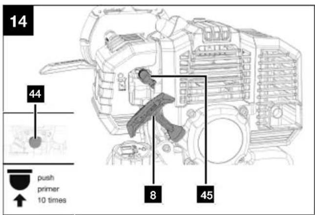
11.1.1.1 When the engine is cold
-
In colder temperatures, press the fuel pump "primer" (44) ten times.
This makes it easier to start the engine. -
Fold the foot (45) up .
-
Start the engine with the pull starter (8). To do this pull out the handle approx. 10 – 15 cm (until you feel a resistance) and then start the engine with a sharp pull. If the engine does not start, repeat the process.
-
Wait for a short time while the engine is running and then apply a little throttle using the throttle (11). The choke (45) turns automatically to the starting position.
-
Grasp the rear handle (5) and the front handle (1). Press the switch lock (4) on the rear handle (5) with the palm of your hand and the throttle (11) with your fingers.
-
The product is ready for use.
-
If the engine does not start even after several attempts, read the "Troubleshooting" chapter.
-
If there is something wrong with the product, such as abnormal noise, stop operating it immediately and switch on the on/off switch to "0" to stop the engine.

CAUTION
After switching off, the product will run on. Wait until the product has come to a complete stop.
11.1.1.2 When the engine is "warm"
- Start the engine with the pull starter (8).
To do this pull out the handle approx. 10 - 15 cm (until you feel a resistance) and then start the engine with a sharp pull.
The product should start after 2 pulls. If the product has still not started, repeat the procedure described under 11.1.1.1. - Grasp the rear handle (5) and the front handle (1). Press the switch lock (4) on the rear handle (5) with the palm of your hand and the throttle (11) with your fingers.
- The product is ready for use.
11.1.2 Shutting the engine off
Note:
Allow the product to run for a short time (approx. 30 seconds) switching it off so that the engine can cool down.
- To switch off the engine, push the on/off switch (3) to the "0" position.
- Disconnect the spark plug connector (6) from the spark plug (6a) to prevent the engine from restarting.
- Put on the supplied transport guard (16a), blade and chain guard (22) and blade guard (29) after every time you work with the product.

CAUTION
After switching off, the product will run on. Wait until the product has come to a complete stop.
11.2 Automatic saw chain lubrication (Fig. 1, 9)
Note:
Before starting work, check the oil level and the function of the chain lubrication.
- Fill the oil tank (23) as described in 10.1.
- To check the product lubrication, hold the chain-saw with the saw chain over a sheet of paper and give it full throttle for a few seconds. You can see on the paper whether the chain lubrication is working.
The amount of oil can be reduced or increased with the adjusting screw (43).
Use an installation spanner (34).
- Clockwise - the amount of oil is reduced (-)
- Counterclockwise - the amount of oil is increased (+)
12 Working instructions

DANGER
Danger of injury!
This section examines the basic working technique for using the product.
The information provided here does not replace the many years of training and experience of a specialist. Avoid any work that you are not adequately qualified for!
Careless use of the product can lead to serious injuries and even death!

DANGER
Hold a minimum distance of 10 m from overhead power lines.
There is a risk of persons being injured due to electric shock.
Notes:
Before switching on, make sure that the product does not touch any objects.
Some noise pollution from this product is unavoidable. Postpone noisy work to approved and designated times. If necessary, adhere to rest periods.
Only process free, flat surfaces with the tool attachment.
Carefully inspect the area to be cut and remove all foreign objects.
Avoid bumping into stones, metal or other obstacles.
The tool attachment could be damaged and there is a risk of kickback.
If solid objects cause blockages, switch off the product immediately, disconnect the spark plug connector from the spark plug and then remove the object.
- Wear prescribed protective equipment.
- Ensure that other people remain at a safe distance from your workspace. Anyone who enters the workspace must wear personal protective equipment. Fragments of the workpiece or broken accessory tools can fly off and cause injury – even outside the immediate working area.
- If a foreign object has been hit, switch off the product immediately and disconnect the spark plug connector from the spark plug. Inspect the product
for damage and perform the required repairs before starting again and working with the product. If the product begins to experience exceptionally strong vibrations, switch it off immediately and check it.
- Do not use the product in a thunderstorm - Danger of lightning strike!
- Check the product for obvious defects such as loose, worn or damaged parts before each use.
- Switch on the product and only then approach the material to be processed.
- Always ensure that you have a safe and firm footing so that you can control the product and maintain your working posture even in the event of unexpected movements.
- Take regular breaks and change your working position regularly.
- Do not exert excessive pressure on the product. Let the product do the work.
- Always hold the product tight with both hands during work. Make sure that you have a secure footing.
- Avoid abnormal postures.
- Check that the shoulder strap is in a comfortable position to make it easier for you to hold the product.
- The tool (34/35) can be stored in the tool bag (33) provided for it.
12.1 Brush cutter/grass trimmer
ATTENTION
All protective covers must be fitted when working with the product!
Note:
Check the nylon thread regularly for damage and whether the cutting thread is still the length specified by the thread cutter.
- Do not hold the tool attachment at an angle.
- Grass is best cut when it is dry and not too long.
- Avoid contact with solid obstacles (stones, walls, fences, etc.).
- Do not use the product to cut wild growth or undergrowth.
- For technical reasons, wet grass and weeds wrap around the drive axle beneath the protective cover (15) while working. Remove this, otherwise the engine will overheat due to excessive friction.
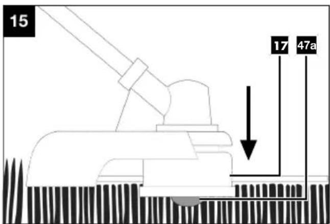
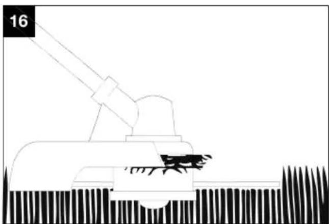
12.1.1 Lengthening the cutting thread (Figs. 15-17)
The grass trimmer is supplied with a filled coil capsule (17).
This line will wear out during work.
So that new thread is fed in, press the trigger (47a) on the coil capsule (17) firmly on the floor with the motor running.
If the thread is initially longer than the cutting circle specified, it is automatically shortened to the correct length by the thread cutter (15b).
Notes:
Check the nylon thread regularly for damage and whether the cutting thread is still the length specified by the thread cutter.
If no thread end is visible:
- Replace the thread coil (47) as described in 14.2.1.
12.1.2 Cutting grass (Fig. 18)
- Cut grass by swivelling the product to the right and left.
- Cut slowly and keep the product tilted forwards by approx. 30^ when cutting.
- Cut long grass in layers from top to bottom.
12.2 Hedge trimmer
12.2.1 Angle adjustment (Fig. 19, 20)

WARNING
Switch off the product and remove the spark plug connector from the spark plug!

CAUTION
The cutter bar must not be swivelled completely back, parallel to the front tubular shaft! Never work with this setting! This position is only used as a transport position.
The cutter bar (28) can be adjusted to the working conditions by swivelling the blade head from +90° to 0°.
- Press both unlocking levers (27a/27b) on the handle (27) and adjust to the desired position.
- To do this, use the handle (27).
- Release both unlocking levers (27a/27b) until they engage into the toothing.
- Before commissioning, check that the unlocking le-vers (27a/27b) are properly engaged.
ATTENTION
The tool attachment may only be used when both unlocking levers are engaged!
12.2.2 Cutting techniques
- Cut out thick branches beforehand with pruning shears.
- The double-sided cutter bar allows cutting in both directions, or using a pendulum movement, swinging the trimmer back and forth.
- When cutting vertically, move the product smoothly forwards or up and down in an arc.
- When cutting horizontally, move the product in a crescent shape towards the edge of the hedge so that cut branches fall to the ground.
- To get long straight lines, it is advisable to stretch guide strings.
12.2.3 Pruned hedges
It is advisable to cut hedges in a trapezoidal shape to prevent the lower branches from becoming bare. This corresponds to natural plant growth and allows hedges to thrive. When pruning, only the new annual shoots are reduced, so that a dense branching and a good screen is formed.
- Trim the sides of a hedge first. To do this, move the product with the direction of growth from bottom to top. If you cut from the top down, thinner branches move outwards and this can create thin spots or holes.
- Then cut the top edge straight, roof-shaped or round, depending on your taste.
- Trim even young plants to the desired shape. The main shoot should remain undamaged until the hedge has reached the planned height. All other shoots are cut in half.
12.2.4 Cut at the right time
- Leaf hedge: June and October
• Conifer hedge: April and August - Fast growing hedge: around every 6 weeks from May
Pay attention to nesting birds in the hedge. Delay the hedge cut or leave this area out if this is the case.
12.3 Pole-mounted pruner

DANGER
Danger of injury!
If the product is jammed, do not try to pull the product out by using force.
- Switch off the engine.
- Use a lever arm or wedge to get the product free.

DANGER
Watch out for falling branches and do not trip.
- The saw chain should have reached maximum speed before you start sawing.
-
You have better control when you saw with the underside of the bar (with a pulling chain).
-
The saw chain must not touch the ground or any other object during or after sawing.
- Ensure that the saw chain does not become jammed in the saw cut. The branch must not break or splinter.
- Also observe the precautions against kick-back (see safety instructions).
- Remove the branches hanging downwards by making the cut above the branch.
- Branched boughs are cut to length individually.
12.3.1 Cutting techniques (Fig. 21)

WARNING
Never stand directly under the branch that you want to saw off!
Possible risk of injury caused by falling branches and catapulting pieces of wood.
In general, it is recommended to position the product at an angle of 60^ to the branch.
Hold the product firmly with both hands during the cutting process and always ensure that you are in a balanced position and have a good stance.
Sawing off small branches:
Place the stop surface of the saw against the branch to avoid jerky movements of the saw when starting the cut. Guide the saw downwards through the branch, applying light pressure.
Be careful not to break the branch prematurely if you have misjudged its size and weight.
Sawing off larger branches:
For larger branches, first choose a relief cut for controlled sawing. To do this, saw an incision in the lower third of the branch (with the top of the blade) (a). Then saw from top to bottom (with the underside of the guide bar) towards the first cut (b).
Sawing off into sections:
Saw off large or long branches in sections so that you have control over the impact location (a, b, c).
- Saw off the lower branches on the tree first to make it easier for the cut branches to fall.
- Once the cut has been completed, the weight of the saw increases abruptly for the operator, as the saw is no longer supported on the branch. There is a risk of losing control of the product.
- Only pull the saw out of the cut with the saw chain running to prevent it from jamming.
- Do not saw with the tip of the tool attachment.
- Do not saw into the bulging branch base, as this will prevent the tree from healing.
12.4 After use
- Always switch the product off before placing it down and wait until the product has come to a standstill.
- Remove the batteries.
- Put on the supplied chainsaw guide bar and chain guard, transport guard or blade guard after each instance of working with the product.
- Allow the product to cool.
13 Cleaning

WARNING
Have maintenance and repair tasks that are not described in this operating manual, carried out by a specialist workshop. Use only original spare parts.

WARNING
Improper maintenance or cleaning work can cause injuries!

WARNING
The product may start unexpectedly and cause injuries and burns during cleaning, repair and maintenance work.
- Switch the product off.
- Remove the spark plug connector from the spark plug.
- Allow the product to cool.

WARNING
Danger of injury when handling the saw chain or the blade!
- Wear cut-resistant gloves.
- Wait until all moving parts have come to a standstill.
- We recommend that you clean the product directly after every use.
- Keep handles and grasping surfaces dry, clean and free from oil and grease. Slippery handles and grasping surfaces do not allow for safe handling and control of the tool in unexpected situations.
- If necessary, clean the handles with a damp cloth washed in soapy water.
-
Never immerse the product in water or other liquids for cleaning.
-
Do not splash the product with water.
- Keep protective devices, air vents and the motor housing as free of dust and dirt as possible. Rub the product clean with a clean cloth* or blow it off with compressed air* at low pressure. We recommend that you clean the product directly after every use.
- Ventilation openings must always be free.
- Do not use any cleaning products or solvents; they could attack the plastic parts of the product. Make sure that no water can penetrate the product interior.
Tool required:
- Rag/cloth*
- Brush*
- Hand brush*
* = may not be included in the scope of delivery!
13.1 Cleaning the spark plug (6a) (Fig. 1, 22)
ATTENTION
Only replace the spark plug when the engine is cold!
Check the spark plug for dirt for the first time after 20 operating hours and clean it with a copper wire brush if necessary. Then service the spark plug every 50 operating hours.
- Pull the spark plug connector (6) off carefully. Do not pull on the cable, but directly on the plug.
- Remove the spark plug (6a) with the enclosed installation spanner (34).
- Remove any dirt from the base of the spark plug (6a).
- Visually inspect the spark plug (6a). Remove any deposits present using a wire brush.
- Check the spark plug gap. Set the electrode gap to 0.6 to 0.7 mm with a feeler gauge.
- The re-assembly takes place in reverse order.
NOTE
A loose spark plug can overheat and cause damage to the engine. Tightening the spark plug too much can damage the thread in the cylinder head.
13.2 Clean the air filter (7c) (Fig. 23)
ATTENTION
Risk of damage!
Operating the engine without a filter element or with a damaged filter element can cause engine damage.
- Never run the engine without the air filter element or with a damaged filter element. This would allow dirt into the engine, which would result in severe damage to the engine.
- Do not use harsh cleaners or petrol to clean the filter.
- Clean the elements by knocking them out on a flat surface. If heavily soiled, wash with soapy water, then rinse with clean water and allow to air dry.
Clean the air filter (7c) every 50 operating hours, replace if necessary.
- Loosen the screw (7a).
- Take off the air filter cover (7) and remove cover (7b).
- Remove the air filter (7c).
- The re-assembly takes place in reverse order. Make sure that the recesses of the cover (7b) are seated in the lugs on the air filter housing.
13.3 Pole-mounted pruner
- Use a brush or hand brush to clean the saw chain and no liquids.
- Clean the groove of the chainsaw guide bar using a brush or compressed air.
- Clean the chain wheel.
13.4 Hedge trimmer
- Clean the cutter bar with an oily cloth after each use.
- Oil the cutter bar after each use with an oil can or a spray.
14 Maintenance
WARNING
Have maintenance and repair tasks that are not described in this operating manual, carried out by a specialist workshop. Use only original spare parts.
WARNING
Improper maintenance or cleaning work can cause injuries!

WARNING
The product may start unexpectedly and cause injuries and burns during cleaning, repair and maintenance work.
- Switch the product off.
- Remove the spark plug connector from the spark plug.
-
Allow the product to cool.
-
Check the product for obvious defects such as loose, worn or damaged parts before each use.
- Check the covers and protective devices for damage and correct seating. Replace them if necessary.
- Regular, careful servicing is required to guarantee the safety level and performance of the product.
- Position the Product on a straight, level surface.
- Do not splash the product with water.
- For safety reasons, replace worn or damaged parts.
- Any work not described in this operating manual must be performed by an authorised specialist workshop only.
Notes:
Maintain the product carefully. Check for misalignment or binding of moving parts, breakage of parts and any other condition that may affect the product's operation. Have damaged parts repaired before using the product.
Tool required:
• Installation spanner (34)
- Phillips screwdriver*
- Bench vice*
- Test gauge*
- File gauge*
- Round file*
- Flat file*
- File holder*
- Grease gun*
* = may not be included in the scope of delivery!
14.1 Gasifier setting
- If the set of blade and saw chain moves at idle or the engine stops by itself when the throttle is released, a carburettor adjustment must be made.
Note:
Have carburettor adjustments (e.g. idle speed) carried out only by qualified specialists to avoid engine damage.
14.2 Brush cutter/grass trimmer
14.2.1 Replacing the thread coil (47) (Fig. 1, 24-28)
- Remove the coil capsule (17) as described in 9.3.
- Open the coil capsule (17) by pressing the two releases (46a) on the coil capsule (17) firmly together at the same time.
- Remove the cover (46) with the pressure spring (46b) of the coil capsule (17) and remove the thread coil (47).
- Pull the thread end of the thread coil (47) out of the thread outlet eyelets (48).
- Remove all thread remnants from the coil capsule (17).
- Take the new thread coil (47) and pull out 10 cm of both trimming lines.
- Clamp the two threads in the opposite notches (47b) in the thread coil (47).
- Insert the new thread coil (47) into the coil capsule (17). The side of the thread coil (47) on which the running direction is indicated by arrows must be visible after insertion.
- The thread coil (47) must be inserted so that the notches (47b) in the thread coil (47) are aligned with the thread outlet eyelets (48) to allow easy threading of the thread.
- Insert the two threads into the respective thread outlet eyelets (48).
- Turn the thread coil (47) slightly back and forth until the integrated lock-in stages of the thread coil (47) slide into the lock-in stages of the coil capsule (17). This prevents unintentional adjustment.
- Replace the cover (46) with the pressure spring (46b) on the coil capsule (17). Make sure that the catches (46a) on the cover (46) fit exactly into the recesses on the coil capsule (17). You can hear them click into place.
Notes:
So that new thread is fed in, press the trigger (47a) on the thread coil (47) firmly on the floor with the motor running.
If the thread is initially longer than the cutting circle specified, it is automatically shortened to the correct length by the thread cutter (15b).
14.2.2 Replacing the thread in the thread coil (47) (Fig. 1, 24-27)
Alternatively, the thread on the thread coil can also be replaced.
You can use the spare thread included in the scope of delivery (32) for this.
-
Remove the coil capsule (17) as described in 9.3.
-
Open the coil capsule (17) by pressing the two releases (46a) on the coil capsule (17) firmly together at the same time.
- Remove the cover (46) with the pressure spring (46b) of the coil capsule (17) and remove the thread coil (47).
- Pull the thread ends of the thread coil (47) out of the thread outlet eyelets (48).
- Remove all thread remnants from the coil capsule (17) and the thread coil (47).
- Bend the new thread in the middle (at approx. 2 metres) and insert the bent part of the thread into one of the notches (47c) of the centre bar of the thread coil (47).
There must now be one thread end in the lower and one in the upper chamber of the thread coil (47). - Wind the two thread ends in the direction of the "WIND CORD" arrow as specified on the top of the thread coil (47).
- Take the thread coil (47) and pull out 100 mm of both threads.
- Then clamp the two threads in the opposite notches (47b) in the thread coil (47).
- Proceed as described in 14.2.1 point 8 above to do this.
14.2.3 Resharpening the thread cutter (15b) (Fig. 17)
The thread cutter (15b) can become blunt over time.
-
If you notice this, loosen the two screws with which the thread cutter (15b) is attached to the protective cover (15). Use the Phillips screwdriver.
-
Then fasten the thread cutter (15b) in a bench vice.
-
Grind the cutting edge of the thread cutter (15b) using a flat file and make sure to maintain the angle of the cutting edge.
-
Refit the thread cutter (15b) onto the protective cover (15).
Note:
Replace or sharpen the thread cutter at the end of each mowing season or as needed.
14.2.4 Grinding the cutting blade (16) (Fig. 1)
Note:
If the blades become slightly dull, you can sharpen them yourself.
- Remove the cutting blade (16) as described in 9.4.
- Fasten the cutting blade (16) in a bench vice.
-
Grind all 3 blades of the cutting blade (16) using a flat file and make sure to maintain the angle of the cutting edge ( 25^ ). Only file in one direction.
-
Replace the cutting blade (16) five times after re-sharpening it at the latest.
Replace the cutting blade (16) immediately if the cutting edge is heavily worn or broken.
An unbalanced cutting blade (16) causes the brush cutter/grass trimmer to vibrate strongly; this poses a danger of injury!
14.2.5 Lubricating the transmission (Fig. 1, 29)
Notes:
Lubricate the drive every 10 to 20 operating hours.
Top up with only a little grease. Under no circumstances overfill!
- Remove the maintenance screw (49) of the brush cutter/trimmer and put some grease in it. Use a 5 mm Allen key (35).
- Refit the maintenance screw (49).
14.3 Pole-mounted pruner

WARNING
Danger of injury when handling the saw chain or the blade!
- Wear cut-resistant gloves.
14.3.1 Checking the chain wheel (39) (Fig. 1, 7-9)
- Turn the fastening nut (19a) anti-clockwise, so that the chain wheel cover (19) is removed. Use an installation spanner (34).
- Turn the chain tensioning screw (42) anti-clockwise to loosen the chain tension. Use the installation spanner (34).
- Remove the chainsaw guide bar (20) and the saw chain (21).
- Check the grooving on the chain wheel (39) with a test gauge.
- If the grooves are deeper than 0.5 mm, do not use the product and consult a specialist dealer. The chain wheel (39) must be replaced.
- Refit the chainsaw guide bar (20) and the saw chain (21) as described under 9.5.
14.3.2 Checking the chainsaw guide bar (20) (Fig. 1, 7-9)
- Turn the fastening nut (19a) anti-clockwise, so that the chain wheel cover (19) is removed. Use an installation spanner (34).
- Turn the chain tensioning screw (42) anti-clockwise to loosen the chain tension. Use an installation spanner (34).
-
Remove the chainsaw guide bar (20) and the saw chain (21).
-
Measure the groove depth of the chainsaw guide bar (20) with the scale on a file gauge.
-
The chainsaw guide bar (20) must be replaced if any of the following apply:
-
The chainsaw guide bar is damaged.
- The measured groove depth is smaller than the minimum groove depth of the chainsaw guide bar (2 mm).
-
The groove of the chainsaw guide bar has narrowed or spread.
-
Fit the chainsaw guide bar (20) and saw chain (21) as described in 9.5.
14.3.3 Replacing the chainsaw guide bar (20) (Fig. 1, 7-9)
- Turn the fastening nut (19a) anti-clockwise, so that the chain wheel cover (19) is removed. Use an installation spanner (34).
- Turn the chain tensioning screw (42) anti-clockwise to loosen the chain tension. Use the installation spanner (34).
- Remove the chainsaw guide bar (20) and the saw chain (21). For dismantling, hold the guide bar (20) swivelled upwards at an angle of approx. 45 degrees to make it easier to remove the saw chain (21) from the groove of the chainsaw guide bar (20).
- Replace the chainsaw guide bar (20) and fit the chainsaw guide bar (20) and saw chain (21) as described in 9.5.
14.3.4 Replace the saw chain (21) and allow it to run in (Fig. 1, 7-9)

DANGER
Serious injuries possible due to tearing or jumping off of the sawtooth!
- Never fit a new saw chain on a worn sprocket or on a damaged or worn guide rail. The saw chain could jump off or break.
- Only use saw chains and blades designed for this product.
-
Before changing the saw chain, clean the groove of the guide bar, as the saw chain may jump out of the bar if it dirty. The deposits can also soak up the chain oil. The consequence would be that the chain oil does not reach the underside of the guide bar, or only to a small extent, and lubrication is reduced.
-
Turn the fastening nut (19a) anti-clockwise, so that the chain wheel cover (19) is removed. Use an installation spanner (34).
-
Turn the chain tensioning screw (42) anti-clockwise to loosen the chain tension. Use the installation spanner (34).
-
Remove the chainsaw guide bar (20) and the saw chain (21).
- Refit the chainsaw guide bar (20) and the saw chain (21) as described under 9.5.
Note:
Only tighten the fastening nut once the chain tension has been set.
With a new saw chain, the tensioning force decreases after some time. Therefore, you must retension the saw chain after the first 5 cuts, or after 10 minutes of sawing at the latest.
14.3.5 Sharpening the saw chain (21)
(Fig. 1)

WARNING
Increased risk of accidents due to an incorrectly sharpened saw chain!
Deviations from the dimensions of the cutting edge geometry during sharpening increase the risk of kick-back of the product.
– Have the saw chain sharpened by a professional.
The saw chain can be resharpened at an authorised specialist workshop. Do not attempt to sharpen the saw chain yourself if you do not have a suitable tool and the necessary experience.

CAUTION
Special tools are required to sharpen the chain; these ensure that the cutting tools are sharpened at the correct angle and to the correct depth.
All cutting links must have the same width and length after sharpening.
Notes:
A sharp saw chain ensures optimum cutting performance. It effortlessly eats through the wood, leaving behind large, long wood chips.
A saw chain is blunt if you have to push the cutting equipment through the wood and the wood chips are very small. With a very blunt saw chain, no chips are produced at all, only wood dust.
- Remove the spark plug connector from the spark plug.
- For sharpening, the saw chain (21) should be taut to allow proper sharpening.
- A round file with a diameter of 4.0 mm is required for sharpening.

CAUTION
Other diameters damage the saw chain and can lead to hazards when working!
- Only sharpen from the inside out. Guide the file from the inside of the cutting tooth to the outside. Lift off the round file when you pull it back.
- First sharpen the teeth on one side. Then turn the saw chain (21) over and sharpen the teeth on the other side.
- The saw chain (21) is worn and must be replaced with a new saw chain (21) when only approx. 4 mm of the cutting tooth is left.
14.3.5.1 Instructions for sharpening the saw chain (21)
- After sharpening, all cutting links must be the same length and width.
- After every third sharpening, the sharpening depth (depth limit) must be checked and the height must be re-filed using a flat file. The depth limit should be set back from the cutting tooth by approx. 0.65 mm. After resetting, round off the depth limit slightly towards the front.
Only use files specifically for saw chains!
Other files have the wrong shape and the wrong edge. Select the diameter of the file according to your chain pitch. Be sure to also note the following angles when sharpening the cutting links.
| Saw chain type | File diameter Top angle Bottom angle Top tilt angle (55°) Standard depth | gauge | |||
 | 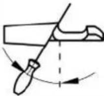 | 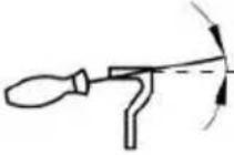 | 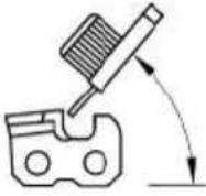 | 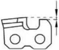 | |
| Clamping rotation angle | Clamping tilt angle | Side angle | |||
| 21PBX approx. 4.8 mm 30° 10° | 85° 0.64 mm | ||||
 |  | ||||
| Depth stop File | |||||
Furthermore, the angle must be maintained for all cutting links.
If the angles are uneven, the saw chain (21) will run erratically, wear out quickly and break prematurely.
Since these requirements can only be met with sufficient and regular practice:
- Use a file holder.
-
A file holder must be used when sharpening the saw chain (21) by hand. The correct filing angles are marked on it.
-
Hold the file horizontally (at the correct angle to the chainsaw guide bar (20)) and file according to the angle marking on the file holder. Support the file holder on the top plate and the depth limiter.
- Always file the cutting link from the inside out.
- The file only sharpens as it moves forward. Lift the file off as you move backwards.
- Do not touch the drive links or fastening links with the file.
-
Turn the file regularly to avoid wear on one side.
-
Use a piece of hard wood to remove the burr from cutting edges.
All cutting links must have the same length, otherwise they will also be of different heights. This causes the saw chain (21) to run erratically and increases the danger of breaking.
14.3.6 Lubricating the transmission
(Fig. 1, 30)
Notes:
Lubricate the drive every 10 to 20 operating hours.
Top up with only a little grease. Under no circumstances overfill!
- Remove the pole-mounted pruner's maintenance screw (50) and put in the grease. Use a 5 mm Allen key (35).
- Refit the maintenance screw (50).
14.4 Hedge trimmer
- Check that the screws in the cutter bar are tight.
- You can smooth out slight nicks on the cutting teeth yourself. To do this, draw an oil stone along the cutting edges. Only sharp cutting teeth provide a good cutting performance.
- Blunt, bent or damaged cutter bars must be replaced.
14.4.1 Lubricating the transmission
(Fig. 1, 31)
Notes:
Lubricate the drive every 10 to 20 operating hours.
Top up with only a little grease. Under no circumstances overfill!
-
Remove the hedge trimmer's maintenance screws (51) and put in the grease. Use a 5 mm Allen key (35).
-
Refit the maintenance screws (51).
15 Storage

DANGER
Risk of fire and explosion!
Storing the product near potential sources of ignition can result in a fire or an explosion. This can lead to severe burns or death.
- Eliminate possible sources of ignition, such as furnaces, hot water boilers with gas, gas dryers, etc.
ATTENTION
Risk of damage!
If the product is not stored properly, the engine can be damaged.
- Store the product protected against dirt, dust and moisture.
- Put on the supplied transport guard (16a), blade and chain guard (22) and blade guard (29) after every time before putting the product into storage.
Tool required:
- Collection bucket*
- Fuel extraction pump*
* = may not be included in the scope of delivery!
15.1 Preparation for storage

WARNING
Do not remove the fuel in enclosed spaces, near fire or when smoking. Petrol fumes can cause explosions and fire.
- Clean and check the product for damage.
- Empty the fuel tank using a petrol extraction pump into an approved container.
- Start the engine and let it run until the remaining fuel is used up.
- Store fuel in tanks specifically designed for this purpose.
- Remove the spark plug (6a) and clean it as described.
- Pour 1 teaspoon of clean 2-stroke oil into the combustion chamber. Pull the starter rope slowly several times to coat internal components.
- Screw the spark plug (6a) back in.
- Store the product in a well-ventilated place or area.
15.2 Drain fuel/oil mixture with a fuel extraction pump (Fig. 1)
In case of storage over a longer period of time, the fuel must be drained.
- Hold a collection bucket under the hose on the fuel extraction pump.
- Unscrew the fuel filler cap (9). The fuel filler cap (9) is connected to an anti-loss device in the fuel tank (10) and thus cannot fall off.
- Push the hose of the fuel extraction pump into the fuel tank (10) and drain out the fuel/oil mixture completely using the fuel extraction pump.
- Retighten the fuel filler cap (9).
16 Transport
Tool required:
- Collection bucket*
- Fuel extraction pump*
* = may not be included in the scope of delivery!
Preparation for transport
- Put on the supplied transport guard (16a), blade and chain guard (22) and blade guard (29) after every time before transporting the product.
- Empty the fuel tank using a petrol extraction pump into an approved container.
- If operational, keep the engine running until the remaining fuel has been used up.
- Remove the spark plug connector from the spark plug.
- Secure the product against slipping using a tension strap, for example.
- The product can be lifted and moved via the handle.
17 Repair and ordering spare parts
After repairs or maintenance, make sure that all safety-related parts are installed and are in perfect condition. All parts which may cause injury must be kept where they are inaccessible to children or others.
ATTENTION
According to the German Product Liability Act, no liability is accepted for damage caused by improper repairs or by not using original spare parts.
Such work should be performed by a customer service centre or an authorised specialists. The same applies to accessory parts.
Spare parts and accessories can be obtained from our Service Centre. To do this, scan the QR code on the front page.
NOTE
Important note in the case of repairs
When returning the product for repair, for safety reasons, ensure that it is free of oil and fuel when it is sent to the service centre.
17.1 Ordering spare parts
Please provide the following information when ordering spare parts:
- Model designation
- Item number
- Type plate data
Spare parts / accessories
| Brush cutter/grass trimmer: | |
| Thread coil - Article no.: 7904800707 | |
| Spare thread - Article no.: 7904800708 | |
| Cutting blade (3-tooth) - Article no.: 7904800709 | |
| Transport protection - Article no.: 7904800710 | |
| Protective cover - Article no.: 7904800711 | |
| Pole-mounted pruner: | |
| Chainsaw guide bar - Article no.: 7904800705 | |
| Saw chain - Article no.: | 7904800704 |
| Guide bar and chain guard – Article no.: | 7904800706 |
17.2 Service information
With this product, it is necessary to note that the following parts are subject to natural or usage-related wear, or that the following parts are required as consumables.
Wearing parts*: Spark plug, air filter
* = not included in the scope of delivery!
18 Disposal and recycling
Notes for packaging


The packaging materials are recyclable. Please dispose of packaging in an environmentally friendly manner.
You can find out how to dispose of the disused device from your local authority or city administration.
Fuels and oils
- Before disposing of the product, the fuel tank and the engine oil tank must be emptied!
- Fuel and engine oil do not belong in household waste or drains, but must be collected or disposed of separately!
- Empty oil and fuel tanks must be disposed of in an environmentally friendly manner.
19 Troubleshooting
The following table shows fault symptoms and describes remedial measures in the event of your product failing to work properly. If you cannot localise and rectify the problem with this, please contact your service workshop.
| Fault Possible cause Remedy | ||
| The product cannot be started. On | On/off switch is defective. Please contact our service department. | |
| The engine is defective. | ||
| Engine brake lever not pressed. Press engine brake lever. | ||
| Spark plug defective. Replace spark plug. | ||
| Fuel tank is empty. Fill with fuel. | ||
| Contaminated fuel. Empty the fuel tank and fill with clean fuel. | ||
| Product works with interruptions. | Internal loose contact. Please contact our service department. | |
| On/off switch defective. | ||
| Poor cutting performance. Saw chain fitted incorrectly. Fit the saw chain correctly. | ||
| Product runs with difficulty/saw chain jumps off. | Chain tension insufficient. | Check the saw chain. Tension the saw chain if necessary. |
| Chain gets hot, smoke development during sawing, discolouration of the rail. | Too little chain oil. | Check the automatic oil system. Top up with chain oil if necessary. |
| Cutter bar becomes hot. | Cutter bar blunt. | Check cutter bar, sharpen or contact our service department. |
| Cutter bar has nicks. | ||
| Too much friction due to lack of lubrication. | Oil the cutter bar. | |
| Poor cutting results. | Thread coil does not have enough cutting thread. | Extend the cutting thread / replace the thread coil. |
| Cutting device is dirty. | Clean the cutting device. | |
| Unusual vibration | Guide rail is loose. | Check that the guide rail is tightly fitted. |
20 EU Declaration of Conformity
Translation of the original Declaration of Conformity
Manufacturer:
Scheppach GmbH
Günzburger Straße 69
D-89335 Ichenhausen
We declare under our sole responsibility that the product described here complies with the applicable directives and standards.
Brand: Parkside
Art. designation: Petrol multi tool –
PBK 4 C4
Item No. 3904820974-3904820980,
39048209915, 39048209959
IAN no. 478559_2410
Series no. 01001-55361
EU directives:
2014/30/EU, 2006/42/EC, 2000/14/EC_2005/88/EC, 2016/1628/EU, 2011/65/EU*
* The object of the declaration described above fulfils the regulations of the directive 2011/65/EU of the European Parliament and Council from 8th June 2011, on the restriction of the use of certain hazardous substances in electrical and electronic equipment.
Applied standards:
EN ISO 11806-1:2022; EN ISO 10517:2019;
EN ISO 11680-1:2021; EN ISO 14982:2009,
AfPS GS 2019:01 PAK; EK9-BE-55(v2):2020;
EK9-BE-56(v4):2020; EK9-BE-98(v2):2020
Conformity assessment procedure:
2006/42/EG - Appendix IV
Notified body: TÜV SÜD
Pole-mounted pruner:
Measured
sound power level ( L_WA ): 112.9 dB
Power (P): 1.4 kW
Notified body:
TÜV SÜD
Industrie Service GmbH,
Westendstrasse 199,
80686 Munich,
Germany
Number:
0123
2016/1628/EU
Emission. No:
e13*2016/1628*2021/1068SHB1/P*0607*00
Documentation authorised representative:
Tobias Ihle
Günzburger Str. 69
D-89335 Ichenhausen
Division Manager Product Center

Andreas Pecher
Head of Project Management
Warranty certificate
Dear Customer,
All of our products undergo strict quality checks to ensure that they reach you in perfect condition. In the unlikely event that your device develops a fault, please contact our service department at the address shown on this guarantee card. Of course, if you would prefer to call us then we are also happy to offer our assistance under the service number printed below. Please note the following terms under which guarantee claims can be made:
- These guarantee terms cover additional guarantee rights and do not affect your statutory warranty rights. We do not charge you for this guarantee.
- Our guarantee only covers problems caused by material or manufacturing defects, and it is restricted to the rectification of these defects or replacement of the device. Please note that our devices have not been designed for use in commercial, trade or industrial applications. Consequently, the guarantee is invalidated if the equipment is used in commercial, trade or industrial applications or for other equivalent activities. The following are also excluded from our guarantee: compensation for transport damage, damage caused by failure to comply with the installation/assembly instructions or damage caused by unprofessional installation, failure to comply with the operating instructions (e.g. connection to the wrong mains voltage or current type), misuse or inappropriate use (such as overloading of the device or use of non-approved tools or accessories), failure to comply with the maintenance and safety regulations, ingress of foreign bodies into the device (e.g. sand, stones or dust), effects of force or external influences (e.g. damage caused by the device being dropped) and normal wear resulting from proper operation of the device.
The guarantee is rendered null and void if any attempt is made to tamper with the device.
- The guarantee is valid for a period of 3 years starting from the purchase date of the device. Guarantee claims should be submitted before the end of the guarantee period within two weeks of the defect being noticed. No guarantee claims will be accepted after the end of the guarantee period. The original guarantee period remains applicable to the device even if repairs are carried out or parts are replaced. In such cases, the work performed or parts fitted will not result in an extension of the guarantee period, and no new guarantee will become active for the work performed or parts fitted. This also applies when an on-site service is used.
- In order to assert your guarantee claim, please contact the service partner shown below. If the complaint is within the guarantee period, we will provide you with a return slip, with which you can return your defective device free of charge to us. It would help us if you could describe the nature of the problem in as much detail as possible. If the defect is covered by our guarantee then your device will either be repaired immediately and returned to you, or we will send you a new device.
Of course, we are also happy offer a chargeable repair service for any defects which are not covered by the scope of this guarantee or for units which are no longer covered. To take advantage of this service, please send the device to our service address.
Processing of warranty claims
To ensure that your request is processed quickly, please follow the instructions below:
- Please have the receipt and article number (e.g. IAN 478559_2410) ready as proof of purchase for all enquiries.
- Please refer to the type plate on the product, an engraving on the product, the title page of your instructions (bottom left) or the sticker on the back or underside of the product for the article number.
- If functional faults or other defects occur, first contact the service department named below by telephone or e-mail.
- You can then send a product recorded as defective to the service address provided to you free of charge, enclosing the proof of purchase (receipt) and stating what the defect is and when it occurred.
- You can view and download these and many other manuals at parkside-diy.com. This QR code will take you directly to parkside-diy.com. Select your country and

PDF ONLINE
parkside-diy.com
Service contact (GB): Service contact (IE):
Name: Forest Park & Garden
Coed Court,
Taffsmead Road
Treforest, Ind. Estate,
Pontypridd CF375SW
Name: Forest Park & Garden
Coed Court,
Taffsmead Road
Treforest, Ind. Estate,
Pontypridd CF375SW
Tel: 00800 4003 4003 Tel: 00800 4003 4003
E-Mail: service.GB@scheppach.com E-Mail: service.IE@scheppach.com
Location: Great Britain Location: Great Britain
Service contact (NI): Service contact (CY):
Name: Forest Park & Garden
Coed Court,
Taffsmead Road
Treforest, Ind. Estate,
Pontypridd CF375SW
Name: GEORGE C SOLOMONIDES
& SON LTD
PO.BOX 56236 / 169, LEONTIOS A'
GR - 3022 LIMASSOL/CYPRUS
Tel: 00800 4003 4003 Tel: 00800 4003 4003
E-Mail: service.Nl@scheppach.com E-Mail: service.CY@scheppach.com
Location: Great Britain Location: Cyprus
Service contact (IT):
Name: Netsend GmbH
Nachtwaid 6
DE - 79206 Breisach am Rhein
Tel: 00800 4003 4003
E-Mail: service.IT@scheppach.com
Location: Germany
Inhaltsverzeichnis
Günzburger Straße 69
D-89335 Ichenhausen
Verehrter Kunde
Günzburger Straße 69
D-89335 Ichenhausen
Division Manager Product Center

Andreas Pecher
Head of Project Management
Garantieurkunde
PDF ONLINE parkside-diy.com
Servicekontakt (DE): Servicekontakt (AT):
4 Fournitures (fig. 1-31)....71
Günzburger Straße 69
D-89335 Ichenhausen
Cher client,
Günzburger Straße 69
D-89335 Ichenhausen
2014/30/UE, 2006/42/CE, 2000/14/CE_2005/88/CE, 2016/1628/UE, 2011/65/UE*
Division Manager Product Center

Andreas Pecher
Head of Project Management
Certificat de garantie
Chère Cliente, Cher Client,
PDF ONLINE
parkside-diy.com
4 Meegeleverd (afb. 1-31).... 105
Günzburger Straße 69
D-89335 Ichenhausen
Geachte klant,
4 Meegeleverd (afb. 1-31)
14.3.5 Zaagketting (21) slijpen (afb. 1)

WAARSCHUWING
Günzburger Straße 69
D-89335 Ichenhausen
Division Manager Product Center

Andreas Pecher
Head of Project Management
Garantiebewijs
Geachte klant,
Servicecontact (NL): Servicecontact (BE):
Naam: TeleMarCom
European Services GmbH
Am Ziegelweiher 24
DE - 61130 Nidderau
Naam: TeleMarCom
European Services GmbH
Am Ziegelweiher 24
DE - 61130 Nidderau
Telefoon: 00800 4003 4003 Telefoon: 00800 4003 4003
E-mail: service.NL@scheppach.com E-mail: service.BE@scheppach.com
Günzburger Straße 69
Günzburger Straße 69
D-89335 Ichenhausen
2014/30/UE, 2006/42/CE, 2000/14/CE_2005/88/CE, 2016/1628/UE, 2011/65/UE*
Division Manager Product Center

Andreas Pecher
Head of Project Management
PDF ONLINE
parkside-diy.com
Günzburger Straße 69
D-89335 Ichenhausen, Germania
Egregio cliente,
Günzburger Straße 69
D-89335 Ichenhausen
2000/14/EG\_2005/88/CE – Allegato: VI
misurato ( L_WA ): 113,0 dB
Potatrice ad asta:
Division Manager Product Center

Andreas Pecher
Head of Project Management
PDF ONLINE
parkside-diy.com
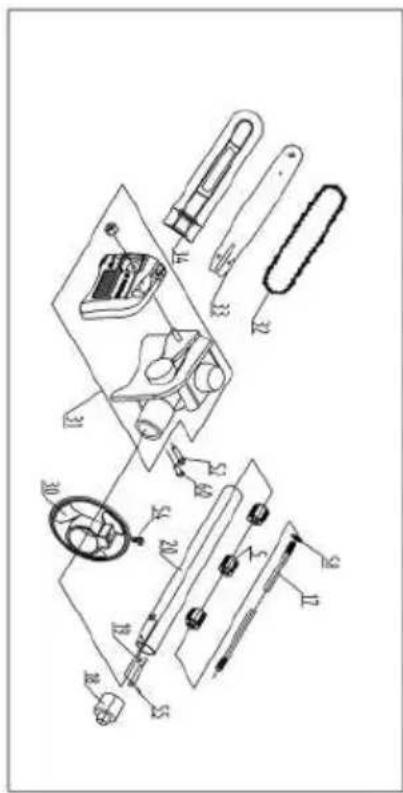
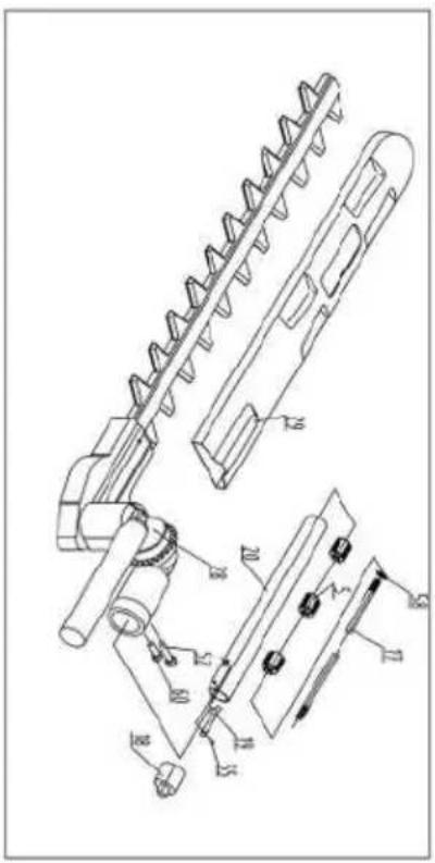
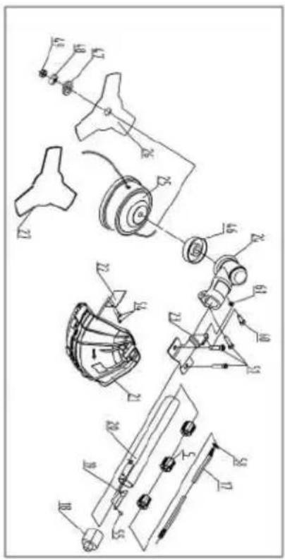
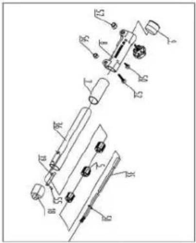
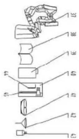
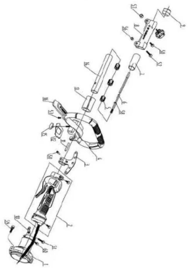
Notizen
CE
SCHEPPACH GMBH
Günzburger Str. 69
D-89335 Ichenhausen


FSC
www.fsc.org
MIX
Paper from responsible sources
C179096 C179096 C179096

FSC
www.fsc.org
MIXTE