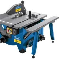
ts 315 GT - Saw SCHEPPACH - Free user manual and instructions
Find the device manual for free ts 315 GT SCHEPPACH in PDF.


User questions about ts 315 GT SCHEPPACH
0 question about this device. Answer the ones you know or ask your own.
Ask a new question about this device
Download the instructions for your Saw in PDF format for free! Find your manual ts 315 GT - SCHEPPACH and take your electronic device back in hand. On this page are published all the documents necessary for the use of your device. ts 315 GT by SCHEPPACH.
USER MANUAL ts 315 GT SCHEPPACH
natural_image
Industrial machine with metal frame and blue frame, no visible text or symbolsscheppach
ts 315 GT
- 527 0611 + 527 1300 + 527 0611 527 0614 + 527 1309 + 527 0611
| D | Tischkreissäge |
| Erzeug Erzeug | |
| GB | Circular Saw Bench |
| Trafalciler for bezuglied inezschel manuel | |
| FR | Scie Circulaire Sur Plateau |
| Moltenenemum crischa | |
| I | Sega Circolare A Banco |
| Trafalciler da struktori na siga | |
| NL | Tafelcirkelzaagmachine |
| Kreking, dan meg kredanfacing | |
| E | Sierra circular de mesa |
| Trafalciler da barmulare ce spesa | |
| P | Serra circular de bancada |
| Trafalciler da menat de barmulare | |
| SE | Bordcirkelság |
| Trafalciler zonged in azkanting | |
| FIN | Tarkistuspyörösaha |
| Ferusteslag postručki vortuček | |
| NO | Bordcirkelság |
| Davertetatsz o gruplakteraszi | |
| DK | Bordrundsav |
| Erzeugdete fa robojnele krajnek | |
| CZ | Stolová kotoučová pila s motorem a vypínačem |
| Plodka a objektinho mota | |
| PL | Pilarka tarczowa stołowa z silnikiem i wyłącznikiem |
| Tehmazsze kryyku unizničnej dožuje | |
| RU | Ferastrau circular |
| Tracuclere din manuál odgina de nortoklan |
scheppach
ts 315 GT
| D | Tischkreissäge | 1 – 8 |
| GB | Circular Saw Bench | 9 – 16 |
| FR | Scie Circulaire Sur Plateau | 17 – 24 |
| I | Sega Circolare A Banco | 25 – 32 |
| NL | Tafelcirkelzaagmachine | 33 – 40 |
| E | Sierra circular de mesa | 41 – 48 |
| P | Serra circular de bancada | 49 – 56 |
| SE | Bordcirkelsåg | 57 – 63 |
| FIN | Tarkistuspyörösaha | 64 – 70 |
| NO | Bordcirkelsåg | 71 – 78 |
| DK | Bordrundsav | 79 – 85 |
| CZ | Stolová kotoučová pila s motorem a vypínaćem | 86 – 93 |
| PL | Pilarka tarczowa stołowa z silnikiem i wyłącznikiem | 94 – 101 |
| RU | Ferastrau circular | 102 – 109 |
Allgemeine Hinweise
- After unpacking, check all parts for any transport damage. Inform the supplier immediately of any faults.
- Later complaints cannot be considered.
- Make sure the delivery is complete.
- Before putting into operation, familiarize yourself with the machine by carefully reading these in structions.
- Use only original scheppach accessories, wearing or replacement parts. You can find replacement parts at your scheppach dealer.
- When ordering, include our item number and the type and year of construction of the machine.
Dear customer,
We wish you much pleasure and success with your new scheppach machine.
NOTE:
In accordance with valid product liability laws, the manufacturer of this device shall not be responsible for damage to and from this device which results from:
- Improper care.
- Noncompliance with the Operating Instructions.
- Repairs made by unauthorized persons.
- The installation and use of any parts which are not original scheppach replacement parts.
- Improper use and application.
- Failure of the electrical system as a result of non-compliance with the legal and applicable electrical directives and VDE regulations 0100, DIN 57113 / VDE 0113.
We recommend that you read through the entire operating instructions before putting into operation.
These operating instructions are to assist you in getting to know your machine and utilize its proper applications.
The operating instructions contain important notes on how you work with the machine safely, expertly, and economically, and how you can avoid hazards, save repair costs, reduce downtime and increase the reliability and service life of the machine.
In addition to the safety requirements contained in these operating instructions, you must be careful to observe your country's applicable regulations.
The operating instructions must always be near the machine. Put them in a plastic folder to protect them from dirt and humidity. They must be read by every operator before beginning work and observed conscientiously. Only persons who have been trained in the use of the machine and have been informed of the various dangers may work with the machine. The required minimum age must be observed.
In addition to the safety requirements contained in these operating instructions and your country's applicable regulations, you should observe the generally recognized technical rules concerning the operation of woodworking machines.
Set-up:
Prepare the workplace where the machine is to be placed. Insure sufficient room to allow safe work without malfunctions. The machine is designed to operate in closed rooms and must be placed stably on firm level ground. Stability is insured by attachment to the ground with 4 screws (Fig. 18).
Transport:
By lifting the machine at the front side it can easily be moved according to your needs in the workshop.
tku 4000
| Supply volume | |
| Circular sawbench tku 4000 with motor and switch | |
| Feet and braces | |
| Sawblade ø 315 mm | |
| Cross-cutting gauge | |
| Suction piece | |
| Sawblade guard | |
| 2.0 m suction hose 50 mm wide | |
| Riving knife | |
| Longitudinal fence with angle bar | |
| Table length extension | |
| Sawblade key | |
| Push stick / push handle | |
| Operating instructions | |
Technical data
| Dimensions L x W x H mm (including table length extension) | 1590 x 590 x 1200 |
| Overall length mm without table length extension | 790 |
| Table size mm | 790 x 590 |
| Table height mm | 850 |
| Sawblade ø min. - max. mm | 300 - 315 |
| Suction connection ø mm | 100 |
| Volume flow m ^3 /h | 565 |
| static depression pA (20 m/s) | 560 |
| Weight kg | 60,0 |
Cutting data
| Cutting height in mm at 90° | 102 |
| Cutting height in mm at 45° | 70 |
| Cutting width in mm at 90° angle cut | 260 |
| Sawblade height adjustment mm | 102 |
| Sawblade inclination range | -2° - +48° |
| Sawblade speed 1/min | 4000 |
| Cutting speed m/sec | 65 |
| Parallel cutting width mm max. | 345 |
| Cross-cutting gauge | 0° - 45° |
Drive
| Motor V/Hz | 110/50 | 230/50 | 400/50 | |
| Power input P1 W | 2200 | 2200 | 3000 | 4200 |
| Power output P2 W | 1500 | 1500 | 2200 | 3000 |
| Speed 1/min | 2800 | |||
| Operating mode | S6/40% | |||
| Motor protection | yes | |||
Noise parameters
The noise emission values determined according to EN 23746 for the sound level and according to EN 31202 (coefficient of correction k3 calculated according to Appendix A.2 of EN 31204) for the sound level at the workplace are as follows, based on the working conditions listed in ISO 7904 Appendix A:
Sound level in dB
Idle running LWA = 90 dB(A)
Operation L_WA = 105 dB(A)
Sound level at the workplace in dB
Idle running L_pAeq = 77,2 dB(A)
Operation L_pAeq = 89,3 dB(A)
A measurement uncertainty allowance K = 4 dB
applies to the mentioned emission values.
Dust emission values
The dust emission values measured according to the “Principles for the inspection of the dust emission (concentration parameters) of wood working devices” of the Technical Committee Wood are below 2 mg/m ^3 . Thus, a permanently reliable compliance with the TRK limit value for wood dust valid in the Federal Republic of Germany can be expected if the machine is connected to a proper operational aspiration with an air speed of at least 20 m/s.
In these operating instructions we have marked the places that have to do with your safety with this sign: △
⚠️ Safety instructions
- Do not use the machine in the open air.
- Please pass on safety notes and instructions to all those who work on the machine.
- The machine must only be used in technically perfect condition in accordance with its designated use and the instructions set out in the operating manual, and only by safety-conscious persons who are fully aware of the risks involved in operating the machine. Any functional disorders, especially those affecting the safety of the machine, should therefore be rectified immediately.
- Only tools which correspond to the European norm, EN 847-1, may be used.
- Observe all safety instructions and warnings attached to the machine.
- See to it that safety instructions and warnings attached to machines are always complete and perfectly legible.
- Caution when working: There is a danger to fingers and hands from the rotating cutting tool.
• Make sure that the machine stands stable ground.
- Check all power supply lines. Do not use lines.
- Keep children away from the machine when nected to the power supply.
- Operating personal must be at least 18 Trainees must be at least 16 years of age, but may only operate the machine under adult supervision.
- Persons working on the machine may not be
from their work.
- The machine must be equipped with a table length extension if a second person is working at the circular sawbench removing cut work.pieces. The second person may not stand anywhere else but at the take-off table end.
- The working space on the machine must be free of chips and wood scrap.
- Wear only close-fitting clothes. Remove rings, bracelets and other jewelry.
- Pay attention to the rotational direction of the motor and tool - see Electrical Connection.
- The safety mechanisms on the machine may not be removed or rendered unusable.
- Cleaning, changing, calibrating, and setting of the machine may only be carried out when the motor is switched off. Pull the power supply plug and wait for the rotating tool to completely stop.
- Switch the machine off and pull power supply plug when rectifying any malfunctions.
- The machine must be attached to a scheppach dust extractor during all work. cycles. Please observe the proper use of this.
- When working on the machine, all safety mechanisms and covers must be mounted.
- Use only sharpened, nick-free and non-deformed saw blades.
- Circular saw blades made from superspeed steel may not be used.
- The splitting wedge is an important safety feature. The work.piece is fed through the splitting wedge, which prevents the cut from closing behind the saw blade and also prevents the workpiece from kicking back.
- Lower the cover onto the work. piece during every work. ing operation. It must stand horizontal above the saw blade.
- Always use a push-stick for longitudinal cuts of narrow work pieces less than 120 mm). The push-stick must be used to prevent you from having to work. with your hands near the sawblade. Stop the machine to repair a failure or remove pieces of wood which have become jammed. Disconnect the mains plug.
- Switch the machine off and pull power supply plug when rectifying any malfunctions.
- The table insert must be renewed when the saw slot is worn down. Pull power supply plug.
- Before the machine is put into operation connected to a dust extractor with a flexible, non-flammable suction hose. The suction should switch on automatically when the machine is switched on.
on• fiWhen leaving the work place, switch the motor off. Pull the power supply plug.
defected off the external power supply of the plant even if only minor changes of place are envisaged. it iProperty reconnect the machine to the supply mains before recommissioning.
years• of Corrosction and repair work. on the electrical installation may be carried out by a qualified electrician only.
- All protection and safety devices must be replaced after divertepleting repair and maintenance procedures.
f the
echanisms
hed saw
steel may
it must be
machine or
Use only as authorized
The machine corresponds to the valid EC guideline.
- The scheppach tku 4000 circular sawbench is defined as a semi-stationary machine in accordance with pr EN 1870-1.
- To transport the machine, grasp the table firmly at the front and at the rear using both hands and lift the machine.
- If an original scheppach base is not used, the machine must be placed firmly upon a stable stand resembling a table. The working height should be 850 mm.
- The machine's workstation is in front of the machine to the left of the sawblade.
- The machining range and surrounding areas of the machine must be clear of interfering foreign matter to prevent accidents occurring.
- Workpieces must be completely free of foreign objects, i.e. nails or screws.
- Before the machine is put into operation connected to a dust extractor with a flexible, non-flammable suction hose. The suction should switch on automatically when the machine is switched on.
- When used in enclosed rooms, the machine connected to a vacuum exhaust unit.
Use the scheppach dust extractor ha 3200 or ha 2600 to remove matchwood or saw dust. The vacuum support flow rate must be 20 m/s. Subatmospheric pressure 1200 Pa.
- The scheppach automatic switching unit is available as a special accessory.
• Type ALV 2 Art. No. 7910 4010 230 V/50 Hz
• Type ALV 10 Art. No. 7910 4020 4 0 0 V/230 V/50 Hz - The vacuum exhaust unit automatically switched on after a 2-3 second delay after the machine tool is turned on. This avoids overtoading the circuit fuse. After turning off the machine tool, the vacuum exhaust unit remains on for an additional 3-4 seconds and is then automatically switched off. Remaining dust is thereby removed by vacuum exhaust, as required by German regulations governing hazardous materials. This results in savings in electricity consumption and reduces noise levels, as the vacuum exhaust unit is on only during machine tool operation.
- For work in commercial spaces, the scheppach dust extractor woova 7 must be used.
- Do not remove or shut off vacuum exhaust systems or dust removers while machine tools are operating.
- The scheppach circular sawbench is designed exclusively for the machining of wood and materials similar to wood. Only original scheppach tools and accessories may be used. Use the required sawblade in accordance with the EN 847-1 norm depending on the type of cut and type of wood (solid wood, plywood or chipboard). Please observe the scheppach Special Tool Accessories.
- The machine must only be used in technically perfect condition in accordance with its designated use and the instructions set out in the operating manual, and only
by safety-conscious persons who are fully aware of the risks involved in operating the machine. Any functional disorders, especially those affecting the safety of the machine, should therefore be rectified immediately.
- Relevant accident prevention regulations and other, generally recognized safety-technical rules must also be adhered to.
- The scheppach machine may only be used, maintained, and operated by persons familiar with it and instructed in its operation and procedures. Arbitrary alterations to the machine release the manufacturer from all responsibility for any resulting damages.
- The scheppach machine may only be used with original accessories and original tools made by the manufacturer.
- Any other use exceeds authorization. The manufacturer is not responsible for any damages resulting from unauthorized use; risk is the sole responsibility of the operator.
it
⚠️ Use only as authorized
CE tested machines meet all valid EC machine guidelines as well as all relevant guidelines for each machine.
- The machine has been built in accordance with state-of-the-art standards and the recognized safety rules. Nevertheless, its use may constitute a risk to life and limb of the user or of third parties, or cause damage to the machine and to other material property.
- The scheppach circular saw bench is constructed exclusively for the sawing of wood. The required saw blade should be inserted according to the cut type and the wood type (solid wood, chip board or plywood).
- The machine must only be used in technically perfect condition in accordance with its designated use and the instructions set out in the operating manual, and only by safety-conscious persons who are fully aware of the risks involved in operating the machine. Any functional disorders, especially those affecting the safety of the machine, should therefore be rectified immediately.
- When used in enclosed rooms, the machine must be connected to a vacuum exhaust unit. Use the scheppach vacuum exhaust unit ha 3200 or ha 2600 to remove matchwood or saw dust. The vacuum support flow rate must be 20 m/s. Subatmospheric pressure 1200 Pa.
- The scheppach automatic switching unit is available as a special accessory. The vacuum exhaust unit automatically switches on after a 2-3 second delay after the machine tool is turned on. This avoids overloading the circuit fuse. After turning off the machine tool, the vacuum exhaust unit remains on for an additional 3-4 seconds and is then automatically switched off. Remaining dust is thereby removed by vacuum exhaust, as required by German regulations governing hazardous materials. This results in savings in electricity consumption and reduces noise levels, as the vacuum exhaust unit is on only during machine tool operation.
- For work in commercial spaces, the scheppach dust remover woova 7 must be used. Do not remove or shut
off vacuum exhaust systems or dust removers while machine tools are operating.
- Any other use exceeds authorization. The manu is not responsible for any damages resulting from unauthorized use; risk is the sole responsibility of the operator.
- The safety, work and maintenance instructions manufacturer as well as the technical data given in the calibrations and dimensions must be adhered to.
- Relevant accident prevention regulations and other, generally recognized safety-technical rules must also be adhered to.
- The scheppach Table Circular Saw may only be used, maintained, and operated by persons familiar with and instructed in its operation and procedures. Arbitrary alterations to the machine release the manu facturer from all responsibility for any resulting damages.
- The scheppach Table Circular Saw may only be used with original accessories and saw blades from the manufacturer.
⚠️ Remaining hazards
The machine has been built using modem technology in accordance with recognized safety rules. Some remaining hazards, however, may still exist.
- The rotating saw blade can cause injuries to fingers and hands if the work piece is incorrectly fed.
- Thrown work pieces can lead to injury if the work piece is not properly secured or fed, such as working without a limit stop.
- Noise can be a health hazard. The permitted noise level is exceeded when working. Be sure to wear personal protective gear such as ear protection.
- Defective saw blades can cause injuries. Regularly inspect the structural integrity of saw blades.
- The use of incorrect or damaged mains cables can lead to injuries caused by electricity.
- The operating instructions supplied with the special accessories must be observed and carefully read when scheppach special accessories are used.
- Even when all safety measures are taken, some remaining hazards which are not yet evident may still be present.
- Remaining hazards can be minimized by following the instructions in „Safety Precautions“, „Proper Use“ and in the entire operating manual.
Assembly
For reasons of packaging technology, your Scheppach machine is not completely pre-installed.
Put the saw tabletop on the reverse for the installation. Insert a piece of cardboard to protect the table surface.
Assembly tools
Included in the supply volume
1 sawblade key size 10/13/17
For reasons of packaging technology, your Scheppach machine is not completely pre-installed.
Put the saw tabletop on the reverse for the installation.
Place a piece of cardboard underneath to protect the table
tinterface.
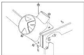
Installation of the dust suction connector, Fig. 1
- Mount the dust suction connector on the casing cover.
of 4 hexagon head cap screws M6 x 10
4 hexagon nuts M6
Installation of the base feet, Fig. 2
- Hand-tighten all screws and nuts.
- Each base foot is screwed on the tabletop with 4 hexagon head cap screws M6x16, 4 serrated lock washers A6,4, and 4 hexagon nuts M6.
The cheese head screw M6 x 40 is fastened with two nuts on the left side of the frame foot and serves as support for the sliding stick. The running gear is fastened on the rear side of the frame feet using two hexagon head cap screws M8 x 16 with nuts and washers.
Then put the foot caps on the base feet.
Installation of the longitudinal and cross struts, Fig. 2
- Each longitudinal and cross strut is screwed on the tabletop with 1 hexagon head cap screw M6x16, 1 serrated lock washer A6,4, and 1 hexagon nut M6.
- Finally tighten all screws and nuts.
Installation of the switch, Fig. 3
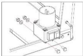
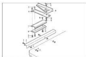
- Fasten the switch mounting part with 2 hexagon head cap screws M8x16, 2 washers A8,4, and 2 hexagon nuts M8 on the tabletop.
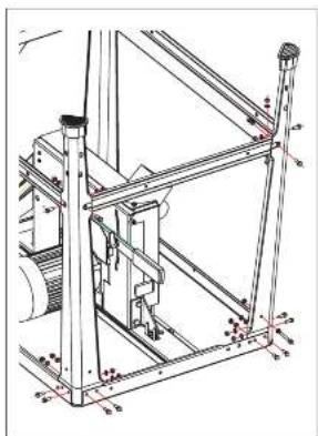
Installation of the table extension, Fig. 4
- Hand-tighten all screws and nuts.
- Fasten the table extension panel with 2 hexagon head cap screws M6x16, 2 washers ∅6 and 2 hexagon nuts M6 on the saw table rear.
- Fasten the supporting frames with 2 hexagon head cap screws M6x16, 2 hexagon nuts M6, and 2 washers ∅6 on the cross strut.
- Fasten the supporting frames with 2 hexagon head cap screws M6x16 and 2 hexagon nuts M6 on the table extension.
Put the circular saw bench on its feet again. Align the machine. Adjust the table extension panel to the height of the saw tabletop, and tighten all screws.
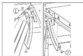
Transport handles and tool holder, Fig. 4.1
Install the transport handles left and right onto the feet of the frame.
Thereto install the hex bolt (A) with a washer 6 mm, the transport handle and a washer 6 mm onto the foot of the frame and secure with a hex nut M6 self-locking, so that the transport handle is still movable.
Install the cylinder bolt (B) M6x16 with a washer 6 mm left and right onto the feet of the frame and secure from the inside with a hex nut M6 self-locking. This will act as a stop during transport of the saw.
Install the cylinder bolt (C) M6x35 with 2 washers and two hex nuts onto the feet of the frame and secure. This is
designed for storage of the tools.
Transport wheels, Fig. 4.2
The transport wheels are fitted to the rear base feet with 2 hexagon bolts, washers and nuts each.
It is important that the wheels touch the ground only after lifting at the transport handles.
Installation of the splitting wedge, Fig. 5
Release the hexagon head cap screw of the splitting wedge carrier with 2 - 3 rotations, but DO NOT UNSCREW.
The adjustment is performed after the installation of the saw blade and must be performed after each exchange.
Finally tighten the hexagon head cap screw.
Installation of the covering cap, Fig. 6
- Fasten the covering cap with 1 saucer-head screw M6x40, 1 washer A6,4, and 1 wing nut M6 on the splitting wedge.
- Insert the suction tube NW50.
Fig. 7
- Fasten the tube support on the right back of the table edge, insert the tube.
- Flange the tube to the lower connector.
Installation of the longitudinal stop, Fig. 8
- Insert the bearings onto the wafer butterfly valve.
- Fasten the wafer butterfly valve with 2 cylinder head screws M6x30, 2 serrated lock washers A6,4, and 2 hexagon nuts M6 on the tabletop.
Installation of the longitudinal stop, Fig. 8.1
- Insert the bearings onto the wafer butterfly valve.
- Fasten the wafer butterfly valve with 2 cylinder head screws M6x30, 2 serrated lock washers A6,4, and 2 hexagon nuts M6 on the tabletop.
Precision end stop. Fig. 9 (Special accessories)
Attach the holding rail A in the area to the right on the front side of the table top C while observing a) Holding rail A is 3 mm deeper than the table top C and b) Holding rail forms a 6 mm offset to the right edge of the table top in the direction of the saw blade.
Adjusting the longitudinal end stop
Now place the longitudinal end stop D incl. the attached stop guide on the guide tube B and clamp this to the table top at scale measurement 70 mm. In order to align the stop guide parallel to the saw blade, measure the distance between the saw blade and the stop guide at the front and at the back. Adjustment can be carried out by loosening the two cylinder screws E. Now clamp the longitudinal end stop to the table top at scale measurement 50 mm. Check that the scale on the guide tube is at 50 mm, readjust if there are deviations. In order to do this, loosen the cross-head screws at the end of the scale, adjust to scale measurement 50 mm and tighten the cross-head screws again.
Cross-cutting gauge, Fig. 10
- Assemble guide profile (1) with sliding plate (2).
2 hexagon bolts M6 x 16
2 hexagon nuts and
2 spring washers
- Insert guide bar (3) and screw it to the left-hand table side with 2 fixing brackets (4).
6 half-round bolts M6 x 16
4 hexagon nuts M6 and
4 spring washers
- Set swinging part (5) onto sliding plate (6) and fix it with T-screw (7).
1 half-round bolt M6 x 20
1 washer 6 mm
1 T-screw M6
- Fasten stop bar (8) onto swinging part (5).
2 half-round bolts M6 x 20
2 wing nuts (9) M6
Check the smooth running of the cross-cutting gauge in all its functions and re-adjust, if required.
Setting the scale
Put a 90^ angle onto the sawblade and the stop bar (8), and release the 2 cap nuts (11). Then set the scale (10) on the mark (12) to 0^ . Finally re-tighten the two cap nuts. Make a trial cut and re-adjust, if needed.
Hint: Swing the cross-cutting gauge to the side when it is not used.
Installation of the saw blade/
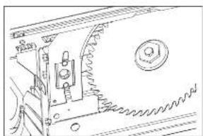
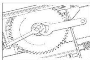
exchange of the saw blade, Fig. 11, 11.1
Installation and exchange of the saw blade may only be performed if the mains plug is disconnected.
Use only original Scheppach saw blades. We do not guarantee for third-party products.
- Lower the saw blade height adjustment.
- Insert the saw blade from the bottom onto the neck flange of the motor shaft. Pay attention to the flattening when inserting the tensioning flange.
- Use a screw driver as a turning lock (Fig. 11.1).
- Tighten the hexagon bolt with the key size 17.
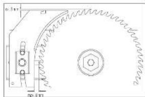
Adjustment of the clipping wedge, Fig. 12
The adjustment of the clipping wedge must be performed after each saw blade exchange.
The clipping wedge must be in alignment with the saw blade. The distance between saw blade and clipping wedge must not exceed 8 mm.
The clipping wedge is an important protection device that guides the work piece and avoids that the cutting joint behind the saw blade is closed. Thus, the blowback of the work piece is safely avoided.
Pay attention to the clipping wedge thickness (see imprinted figures on the clipping wedge). The clipping wedge must not be thinner than the saw blade base body and not thicker than the cutting joint width.
Putting into operation
Please observe the safety instructions.
The machine may only be operated with completely installed protection and safety devices.
After the connection to the mains supply the machine is operational.
The covering cap must be lowered onto the work piece during each work cycle.
To perform hidden cuts, release the wing cut, and then remove the support sheet with the covering cap.
Inclination adjustment of the sawblade, Fig. 13/14
Attention: When inclining, to not exceed the maximum of 95 mm on the scale!
After releasing the two wing nuts A, the sawblade can be continuously adjusted from 0^ to 45^ (see scale C) with the hand wheel B at the side.
Before every use of the machine, adjust the setting of the degrees. Make a trial cut. Re-adjust the scale pointer, if required.
After every setting, re-tighten both wing nuts.
Sawblade height adjustment, Fig. 13
The height is adjusted by means of the hand wheel D at the machine front side. The cutting height selected can then be precisely set by means of scale D.
Longitudinal cuts, Fig. 15
Use the longitudinal stop for parallel cuts. Use the stop ruler with the upper stop side (1) for cutting works above 120 mm and with the lower stop side (2) for cutting widths below 120 mm. Guide the work piece with the included push stick.
Cross cuts, no figure
Insert the cross cutting jig or the slide carriage to perform cross and angular cuts. Both parts are available as special accessory. The adjustment scale of the cross cutting jig ranges from 0 - 90°.
Notes on working
Working on circular saw benches
Cutting narrow work pieces, Fig. D
(Width of work piece less than 120 mm)
Tool: circular saw blade for length cuts
Work step:
Adjust the parallel stops to the width of the intended work piece. Feed work piece with both hands. In the area of the saw blade use the push stick and push the work piece beyond the splitting wedge. When working with shorter work pieces use the push stick from the very beginning.
Cutting strips and corners, Fig. C
Tool: Circular saw blade for line cuts
Work step:
Install parallel stops with a flatter guide side or use lower auxiliary stops. Feed the work piece with a push board until the end of the work piece is in the area of the splitting wedge. Prevent longer work pieces from tipping over at the end of the cutting process by using the bench extension.
Note: Attachments which require a connection to parts of the machine must be bolted down. Screw clamps can only provide secondary connections to machines.
Cross-cutting narrow work pieces, Fig. D
Tool: Fine toothed cross cut blade
Work step:
Adjust diversion strip so that sawed off pieces cannot come into contact with the protruding part of the saw blade. Feed the work piece only with the cross stop or with the cross slide. Do not use hands to remove excess wood from the area of the work piece.
Blind cutting, mortise and tenon, Fig. E + F
Work step:
Adjust the splitting wedge to be the rear machine cover (Setting for blind cut). Adjust the parallel stop to the mortise or tenon dimension and secure against sideward movements.
Feed work piece with feeding batten. Right hand secures the work piece against falling over. Do not place hand on the forward edge of the work piece.
After cutting, return the feeding batten with the work piece. The measurements of the work piece receiver rebate of the feeding batten must correspond to the work piece measurements. In order to apply sufficient pressure to the work piece, the notching depth must be approx 1 mm less than the thickness of the work piece. If the mortise depth or the tenon height attains the measure of the stop height C, than a detachable board B secured with screws A can be used for raising the stop.
Blind cutting, rebates, Fig. G
Tool: circular saw blade for line cuts
Work step:
When rebating on the stop, select the order of cuts so that the cut strip comes out on the side of the saw blade not lacing the stop.
In order to perform blind cuts and rebates, remove the upper machine cover or flap open the safety cap and lower the splitting wedge. Carefully feed the work piece (W necessary, secure rear stop against swinging motions).
Cutting of wedges, Fig. H
Tool: circular saw blade for line cuts
Work step:
Keep the saw slot in the table as narrow as possible. Feed the work piece with the wedge cutting batten past the splitting wedge. Remove wedge at that point. Only use wedge cutting battens that feed the wedge safely along the table (weather boards or cover strips that go along the entire length of the wedge cutting batten).
Insert cutting of shorter work pieces, Fig. K
Work step:
Remove the splitting wedge and the upper machine cover, or flap open the safety cap. Lighten the splitting wedge mounting. Adjust cross stop to the setting measurements and secure with two clamps (use wooden blocks on table). Put work piece against cross stop and evenly lodge. Feed work piece up to the cleft or to the second cross stop. Remove work piece.
Insert cutting of larger work pieces, Fig. L
Work step:
Remove splitting wedge and upper machine cover. Attach set cutting attachment to parallel stop. Adjust back kick block with the work piece receiver and the check block. Put work piece against the back kick block, evenly lodge and feed up to the check block and retract in a safe position. After insert cutting: Promptly reinstall the wedge and the upper cover.
Servicing
Pay attention to the safety instructions on page GB8.

Turn off the motor and pull the plug before servicing or cleaning the machine.
All protection and safety devices must be immediately assembled again following repairs and servicing.
- The assemblage of the circular saw is largely service-free, including the electric motor. Exceptions to this are the normal wear and tear of the saw blades as well as the bench insert. If needed, exchange the used bench insert.
- The bench surface should always be kept resin-free.
- Keep the saw blade protection box free of wood and chip residue. When the power plug is pulled, open the protection box cover and remove any saw dust obstructions.
- The motor brake is maintenance-free and will function for at least 5000 switch operations. If the after-running time exceeds ten seconds, please inform the manufacturer.
Belt change - Belt tension fig. 18 / 19
Attention! Pull the mains plug out.
1 Dismount protective cover (A).
Loosen the 9 cross-head screws, turn round the swing gate at 45^ using the hand wheel (B) and remove the protective cover.
2 By loosening both hex nuts (C), you slack the drive belt.
3 Now you can take off the drive belt from the front and after that from the back belt pulley.
Mount the new driving belt in reverse order.
Pay attention, it should be laid out on the complete belt pulley surface.
4 Then stretch the drive belt, tighten both hex nuts (C) and remount the protective cover (A) on the housing.
Due to a low belt tension a loss of power is possible. Check the belt tension and fix the problem by stretching the drive belt.
Follow the procedure as mentioned in chapter 1, 2 and 4.
Electrical connection
The installed electric motor is completely wired ready for operation.
The customer's connection to the power supply system, and any extension cables that may be used, must conform with localregulations.
Motor braking unit
The scheppach tku 4000 circular saw bench is fitted with an automatic motor braking unit which becomes effective as soon as the driving motor is switched off.
Important remark:
The electric motor is designed for the S 6 / 40 % operating mode.
Therefore, the motor is automatically switched off in the event of an overload. The motor can be switched on again after a cooling down period that can vary.

Defective electrical connection cables
Electrical connection cables often suffer insulation damage.
Possible causes are:
- Pinch points when connection cables are run through window or door gaps.
- Kinks resulting from incorrect attachment or laying of the connection cable.
- Cuts resulting from running over the connecting cable.
- Insulation damage resulting from forcefully pulling out of the wall socket.
- Cracks through aging of insulation.
Check electrical connection cables regularly for damage. Make sure the cable is disconnected from the mains when checking.
Electrical connection cables must comply with the regulations applicable in your country.
Such defective electrical connection cables must not be used as the insulation damage makes them extremely hazardous.
Single-phase motor
- The mains voltage must coincide with the voltage specified on the motor's rating plate.
- Extension cables up to a length of 25-m must have a cross-section of 1.5 mm ^2 , and beyond 25 m at least 2.5 mm ^2 .
- The connection to the mains must be protected with a 16 A slow-acting fuse.
Three-phase motor
- The mains voltage must coincide with the voltage specified on the motor's rating plate.
- The mains connection and the extension cable must have 5 conductors: 3 phase conductors + 1 neutral conductor + 1 earth conductor.
- The extension cable must have a minimum cable cross-section of 1.5 mm^2 .
- The connection to the mains must be protected with a 16 A slow-acting fuse.
- The rotating direction must be checked when the machine is connected to the mains or re-sited. If necessary, the polarity will have to be changed over (wall socket).
Only a qualified electrician is permitted to connect the machine and complete repairs on its electrical equipment.
| In the event of enquiries please specify the following data: | |
| 1. | Motor manufacturer |
| 2. | Type of current of the motor |
| 3. | Data recorded on the machine's rating plate |
| 4. | Data recorded on the switch's rating plate |
| If a motor has to be returned, it must always be dispatched with the complete driving unit and switch. | |
Optional equipment
| Sliding table carriage1200 mm:Part no. 7951 00001500 mm:Part no. 7951 0901 | Sliding table carriage1300 mm:Part no. 5278 0701 |
| Table width extensionPart no. 7961 0901 | |
| Automatic switch-on unitTyp ALV 2: Part no. 7910 4010Typ ALV 10: Part no. 7910 4020 | |
EC Declaration of Conformity
We, scheppach Fabrikation von Holzbearbeitungsmaschinen GmbH Günzburger Str. 69, D-89335 Ichenhausen hereby declare that the machine named below corresponds to the relevant safety and health requirements of the EC guide lines specified below in its design and construction and in the version which we introduced to the market. This declaration becomes invalid if changes are made to the machine without our consent.
Machine description:
Circular saw
Machine model:
tku 4000
Relevant EC directives:
EC machine directive 98/37/EG (<28.12.2009), EC machine directive 2006/42/EG (>29.12.2009), EC Low voltage directive 2006/95/EWG, EC-EMV directive 2004/108/EWG.
Applied harmonized European Standards:
EN12100-1, EN12100-2, EN294, EN349, EN418, EN847-1, EN954-1, EN1088, EN1870-1, EN60204-1, EN55014, EN60555-2, EN60555-3
Applied national technical standards and specifications, especially: ISO 7960
Notified body within the meaning of Annex VII
on behalf of Werner Hartmann (Technical manager)
Troubleshooting
| Failure Possible cause Solution | ||
| Saw blade gets loose after turning off the motor | a) Fastening nut tightened insufficiently | a) Tighten fastening nut, M20 left-handed thread |
| Motor does not start a) Fastening nut | tightened insufficiently | a) Check the mains fuse. |
| b) Extension cable defect b) See “Electrical Connection” in the operating manual, pages GB 16 | ||
| c) Connections on the motor or switch defect | c) Have it checked by an electrician Brake does not bleed | |
| d) Motor or switch defect d) See “Electrical Connection” in the operating manual, pages GB 16 | ||
| Motor runs forward or backwards Capacitor defect Have it exchanged by an electrician | ||
| Engine is giving full power,Saw blade is running to slow | Drive belt too slack | Stretch drive belt |
| No motor output, turns off automatically | Overload by dull saw blade, thermoprotection is triggered | Insert a sharpened saw blade; motor can be turned on again after the cooling period |
| Burns on the cutting surface | a) Fastening nut tightened insufficiently | a) Insert a sharpened saw blade |
| c) with longitudinal cuts | c) Longitudinal stop not parallel | c) Exchange the longitudinal stop |
| d) with cross cuts | d) Slide carriage not parallel | d) Align the slide carriage with the saw blade |
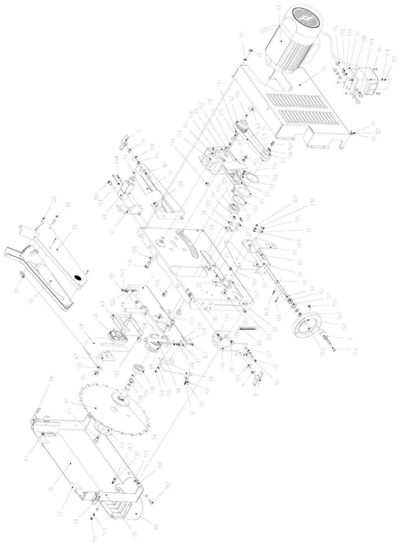
text_image
Technical diagram of an electronic device with numbered components for identification and assembly reference.

text_image
Technical schematic diagram of an electronic device with numbered components and exploded view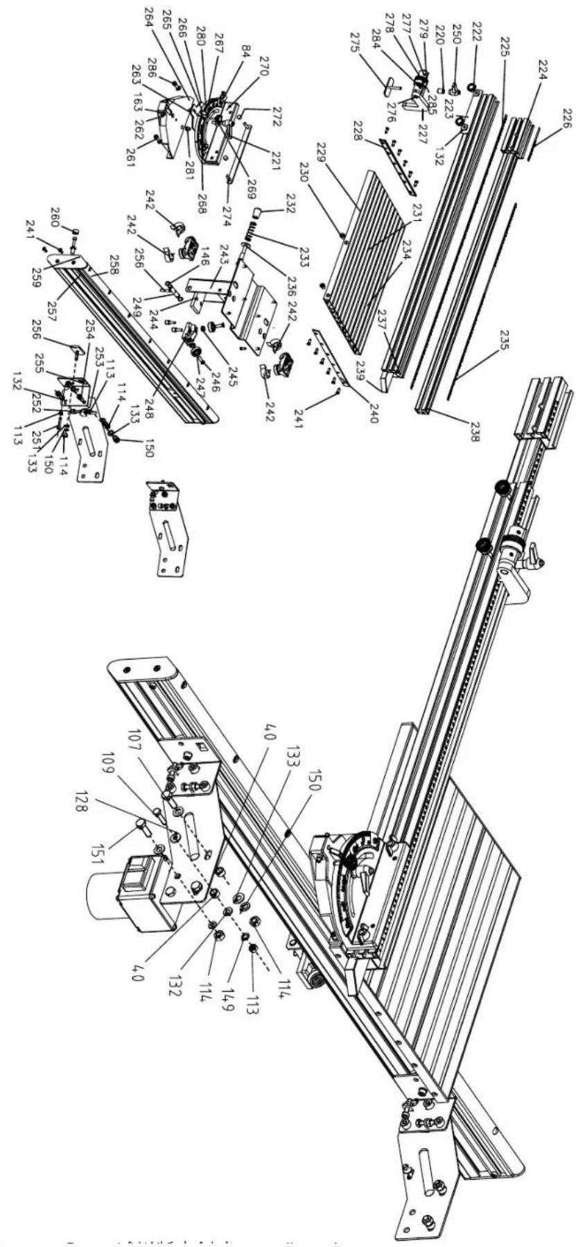
text_image
Technical diagram of a mechanical assembly with numbered components and exploded view, likely for engineering or manufacturing documentation.

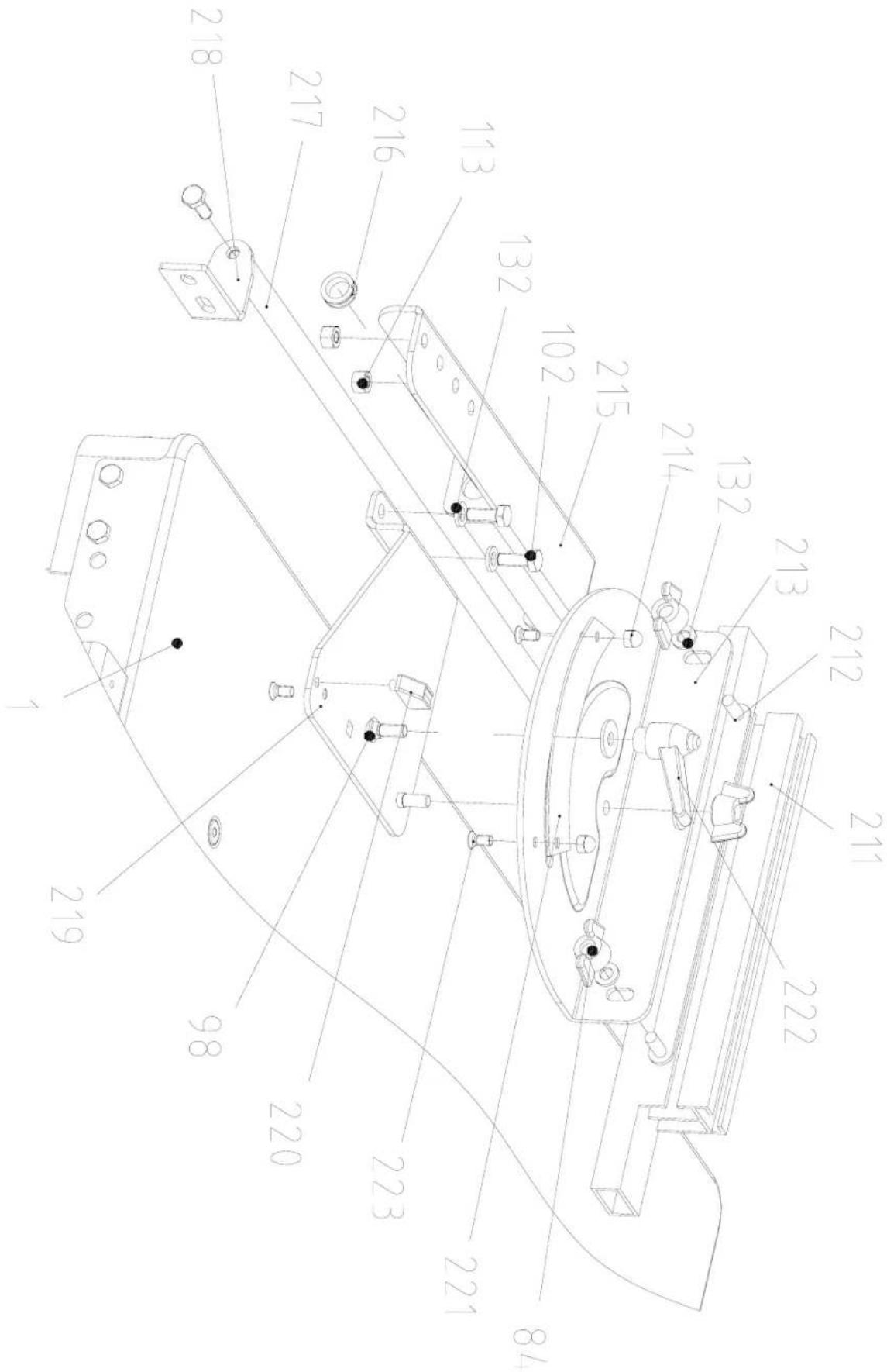
text_image
Technical schematic diagram with numbered components, likely a mechanical or electrical assembly layout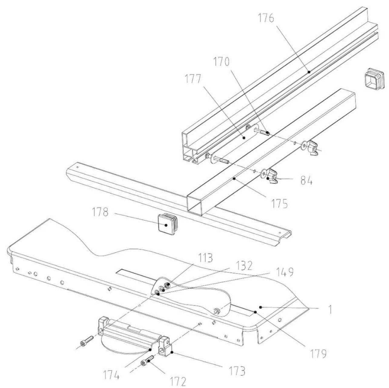
text_image
Technical diagram of a mechanical assembly with numbered components, including frame elements and mounting brackets.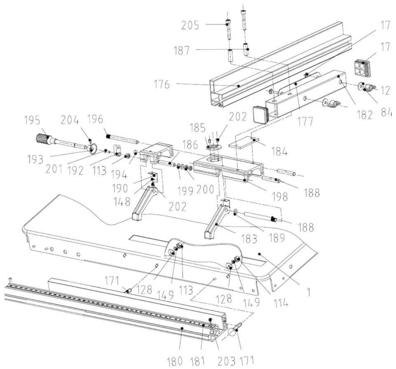
text_image
Technical diagram of a mechanical assembly with numbered components and labeled partsProduction

Only for EU countries. Based on several electronic tools together with transatlantic media makers will be observed of European directors 2002/06/ED on mixed electrical and electronic equipment and its implementation in accordance with national low, electric tools that have reached the end of their life must be collected separately and returned to an environment by compatible recycling facility.

Theorem 1.2. (Theorem 1.3) Let be a finite field and let (x) be the set of all elements of such that

The Ground Truth image displays a single, solid horizontal line. According to Rule 2 (UNDERSCORE & LINE RULES), if the GT contains lines used for stylistic emphasis or as background elements (like ruled paper), the OCR result must ignore them. The line in the GT is clearly a stylistic or background line, not a placeholder for text. Therefore, the OCR should not have output any underscores. Outputting `____` constitutes an error under Rule 2, as it hallucinates placeholder symbols where none are semantically intended. Hence, the OCR result is inconsistent with the Ground Truth.

The image is too blurry to recognize any text content.
This appliance is covered by a 24 month's guarantee
- The guarantee room only material and construction table. Lavity parts are second level
chips, redness and coryal splabion seed. 36 porcens rilymans spapach
parla.
- The purpose of this version: Transport design, using parts, developed up from
Improve use or failure to observe operating instructions, electrical faults, electrical
caubics are not observed.
- Suppose claims are valid only if no repairs have been made by a third party. The accuracy
certificate is only valid with the invoice.
(1) 2017年1月1日
[Unreadable]
-
La construction scored by us "burs de reen
-
In the case of the study, the study was a result of a positive effect on the outcome of the study.
The following table provides the results of the results:
- 15.2017a decide to undergo efforts, coverage of remote and automated
-
Il's grupina hall plasr belsakima on malataa al tevicaestuistet. Harcenduta
-
2023: 10th week, following the annual EPS of \$1.457, down 10% of the company's earnings per share.
The following table is provided in the image:
-
Dokument, anion in the case of the Tensomodems citrates
-
17-400 (2018) 30:45:45 (2019) 30:45:45 (2019)
Line specificity is about p_0 in the case of ordering.
Figure 1. Summary
(1) 2017年1月1日
11 confirm the garden for so-called and natural to corn a balance.
1. 2017年
Cairo - 2016
N. 10000000000000000000000000000000000000
The following text in the image is:
-
100% of the people are in the country, and
-
2017, 30: 19:45, 19:46, 19:47, 19:48, 19:49, 19:50, 19:51, 19:52, 19:53, 19:54, 19:55, 19:56, 19:57, 19:58, 19:59, 19:60, 19:61, 19:62, 19:63, 19:64, 19:65, 19:66, 19:67, 19:68, 19:69, 19:70, 19:71, 19:72, 19:73, 19:74, 19:75, 19:76, 19:77, 19:78, 19:79, 19:80, 19:81, 19:82, 19:83, 19:84, 19:85, 19:86, 19:87, 19:88, 19:89, 19:90, 19:91, 19:92, 19:93, 19:94, 19:95, 19:96, 19:97, 19:98, 19:99, 20:00
The following table is provided in the image.
Take - FNSLAND
Talis betestie prototagismus. Zu linken den bilanzi
-
Televisions, payments, and investment activities
-
2008 Novate a Roudzak - AVE - ja zvr hizsikaja. Visišen ošč: 121 e 21 nezazan.
The following table provides the information in English:
- In situ at the introus posterior junction, the upper bound is given with the upper bound in respect to the
at Xie and Iaunanet, Tukhao unibuata
Takurodistus on volmasza vali azokuliti ranze.
m = 311
Barrill - NORUS
-
-
-
-
-
-
-
-
-
-
-
-
-
-
-
-
-
-
-
-
-
-
-
-
-
-
-
-
-
-
-
-
-
-
-
-
-
-
-
-
-
-
-
-
-
-
-
-
-
-
-
-
-
-
-
-
-
-
-
-
-
-
-
-
-
-
-
-
-
-
-
-
-
-
-
-
-
-
-
-
-
-
-
-
-
-
-
-
-
-
-
-
-
-
-
-
- 99.
-
-
-
-
-
-
-
-
-
-
-
-
-
-
-
-
-
-
-
-
-
-
-
-
-
-
-
-
-
-
-
-
-
-
-
-
-
-
-
-
-
-
-
-
-
-
-
-
-
-
-
-
-
-
-
-
-
-
-
-
-
-
-
-
-
-
-
-
-
-
-
-
-
-
-
-
-
-
-
-
-
-
-
-
-
-
-
-
-
-
-
-
-
-
-
-
17.5000
-
"Jawthorn"
-
9/5 investor on call (assistant) and interest in the past 40% of the stock price.
[Unreadable]
Forfeil - 01MWAR
Eh devas machte vde: i Eom 24 miharau gurni
-
In addition, the job is a member of the company, and the company is a member of the company.
-
ANALYSIS (2005) (2011) [4] (2012) [3] (2013) [4] (2014) [5] (2015) [6] (2016) [7] (2017) [8] (2018) [9] (2019) [10] (2020) [11] (2021) [12] (2022) [13] (2023) [14] (2024) [15] (2025) [16] (2026) [17] (2027) [18] (2028) [19] (2029) [2030]
100000
(1) _i (2) _i (3) _i (4)
anarmart-reversional (in.)
- Seviny slu rizklas antecima lebelroje: nuvi sli jnuu a zraokrot enlakhu: zrslu su
sind, alonarisket, vink, womam (for kardia) varrangibin, adant as
(1) 2014, a Canadian Bank, Canada branch, financial sector, financial sector, financial sector, financial sector, financial sector, financial sector, financial sector, financial sector, financial sector, financial sector, financial sector, financial sector, financial sector, financial sector, financial sector, financial sector, financial sector, financial sector, financial sector, financial sector, financial sector, financial sector, financial sector, financial sector, financial sector, financial sector, financial sector, financial sector, financial sector, financial sector, financial sector, financial sector, financial sector, financial sector
1.217E, tefrometevi 0439, EIV 3141642F 0142, el mabel el (fash) a flowman
- VSE: Standardized 100. LIM OF TENDER OF 15 METAL AND OTHERS OF PAPER
1.0 mg/350
- 4520501 a [ola lari igényesel coss organ terendezes azelben lek erelyesten,
strengthen: Raiman & Chemeyer, New Economic Promotion
A. 16.000-000000000000000000000000000000000
Barnett - KONKAWER
(1) 2017年1月1日
In lele zasodne na svishu zinika 21 medica:
- Zimics en erfisija ien na creby malentih a na coninoetra chyte. Chyte dael x
The following table is provided in the image.
In this period, the following forms of the social generation:
- Garanda de proleguje con la raterjana - il suo noregale. Osteo que se
m = 311
GALNTJE - SCLORENEK
Za to non-zea Warr n.dino 24 measino paraclo
-
Garantía se popular incluyos na paraje y matrue al imidual. "Civariere raje herro"
-
Cota, 2016, 1954, 1955, 1956, 1957, 1958, 1959, 1960, 1961, 1962, 1963, 1964, 1965, 1966, 1967, 1968, 1969, 1970, 1971, 1972, 1973, 1974, 1975, 1976, 1977, 1978, 1979, 1980, 1981, 1982, 1983, 1984, 1985, 1986, 1987, 1988, 1989, 1990, 1991, 1992, 1993, 1994, 1995, 1996, 1997, 1998, 1999, 2000, 2001, 2002, 2003, 2004, 2005, 2006, 2007, 2008, 2009, 2010, 2011, 2012, 2013, 2014, 2015, 2016, 2017, 2018, 2019, 2020, 2021, 2022, 2023, 2024, 2025, 2026, 2027, 2028, 2029, 2030,
(1)
-
The net is estimated as an interest on offering ab revsarely, resulting data
-
A small group of 100% of the population, but the population is not in the U.S., or it is a general entity,
The following table provides the information in English and local English.
The Ground Truth image displays a single, solid horizontal line, which is a stylistic or background element (like a ruled paper line or separator), not a placeholder for text. According to Rule 2, such stylistic/background lines must be ignored by the OCR result. The OCR content provided is "", which consists of no characters. This correctly represents the line in the GT by ignoring it entirely. Since the OCR output includes no underscores for this line, this complies with the “Stylistic/Background Lines (Ignore)” rule. Therefore, the OCR result is consistent with the Ground Truth.
Fig. 1
text_image
Technical diagram of a mechanical assembly with labeled components and angular markings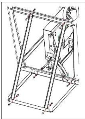
natural_image
Technical line drawing of a mechanical assembly with no visible text or symbolsFig. 4
Fig. 2
natural_image
Technical line drawing of a mechanical assembly with no visible text or symbols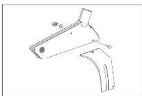
natural_image
Technical line drawing of a mechanical bracket component (no text or symbols)Fig. G
Fig. 3
natural_image
Technical line drawing of a mechanical assembly with mounting brackets and bolts (no text or symbols)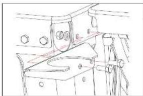
natural_image
Technical line drawing of a mechanical assembly with no visible text or symbolsFig. 7
Fig. 5
natural_image
Technical line drawing of a mechanical component with no visible text or symbols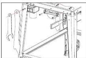
natural_image
Technical line drawing of a mechanical frame assembly with no visible text or symbols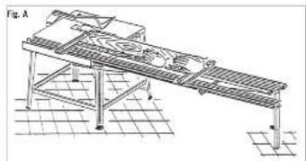
natural_image
Technical line drawing of a mechanical assembly with grid base and support structure (no text or symbols)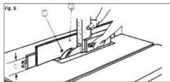
text_image
Fig. 5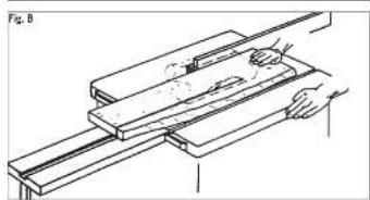
natural_image
Technical line drawing of a mechanical assembly with no visible text or symbols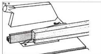
natural_image
Technical line drawing of a mechanical assembly with no visible text or symbols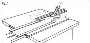
natural_image
Technical line drawing of a mechanical assembly or clamp device (no text or symbols visible)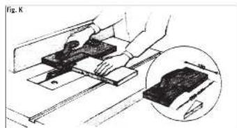
natural_image
Illustration of a hand using a tool to adjust or install a component, with an inset showing a magnified view of the component (no text or symbols present)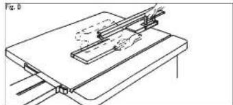
natural_image
Technical line drawing of a mechanical assembly with no visible text or symbols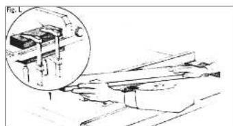
natural_image
Technical line drawing of a mechanical assembly with an inset showing a component (no text or symbols)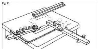
natural_image
Technical line drawing of a mechanical assembly with levers and components (no text or symbols)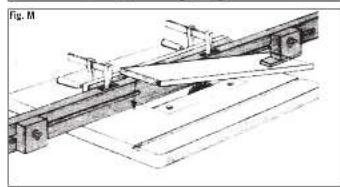
natural_image
Mechanical assembly diagram showing a lever mechanism with rotating components and guide rails (no text or labels)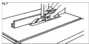
natural_image
Technical line drawing of a mechanical assembly with a tool and bracket (no text or symbols)Fig. 9

natural_image
Technical line drawing of a mechanical assembly with no visible text or symbols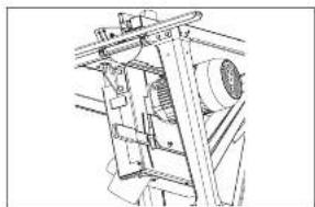
natural_image
Technical line drawing of a mechanical device with no visible text or symbolsFig. 10
text_image
Technical diagram of a multi-layered mechanical or electronic component with labeled parts and dimension lines
natural_image
Technical line drawing of a mechanical assembly or conveyor system (no text or symbols visible)Fig. 11
natural_image
Technical line drawing of a mechanical device with gears and springs (no text or symbols)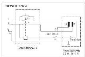
text_image
210 WSD Rx 1 Phase Switch BAN/2317 210 WSD Rx 1 Phase 22.4V, 55.10 V Transistor A M S S S Transistor Transistor 210WSD Rx 22.4V, 55.10 VFig. 12
text_image
0.3mm 50.8mm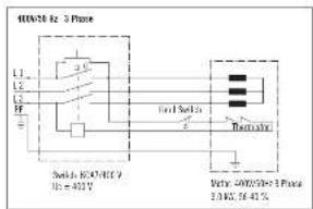
text_image
400kV to 3 Phase L1 L2 L3 FF Switch to 3/47/46.9 Hz = 402 V Final Switch Recharge Wet: 600kV to 3 Phase 2.1402, 74-87.5Fig. 13
text_image
Technical diagram showing mechanical assembly with labeled parts and directional arrows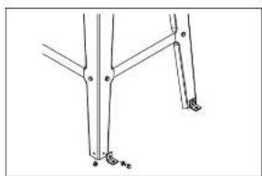
natural_image
Pure mechanical linkage diagram without any text, numbers, or symbolsFig. 14
Fig. 15
Fig. 16
Fig. 17
Fig. 18