108A-0050-00-00 - Jack Vevor - Free user manual and instructions
Find the device manual for free 108A-0050-00-00 Vevor in PDF.

User questions about 108A-0050-00-00 Vevor
0 question about this device. Answer the ones you know or ask your own.
Ask a new question about this device
Download the instructions for your Jack in PDF format for free! Find your manual 108A-0050-00-00 - Vevor and take your electronic device back in hand. On this page are published all the documents necessary for the use of your device. 108A-0050-00-00 by Vevor.
USER MANUAL 108A-0050-00-00 Vevor
Technical Support and E-Warranty Certificate www.vevor.com/support
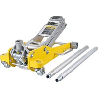
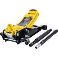
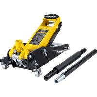
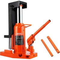
TOE JACK
MODEL:108A-0050-00-00
We continue to be committed to provide you tools with competitive price. "Save Half", "Half Price" or any other similar expressions used by us only represent estimate of savings you might benefit from buying certain tools with us compared top brands and does not necessarily mean to cover all categories of tools offered are kindly reminded to verify carefully when you are placing an order with us actually saving half in comparison with the top major brands.
VEVOR®
TOUGH TOOLS, HALF PRICE
Toe jack
MODEL:108A-0050-00-00

natural_image
3D rendering of a mechanical device with orange cylindrical body, black base, and lever handle (no text or symbols visible)NEED HELP? CONTACT US!
Have product questions? Need technical support? Please feel from contact us:
Technical Support and E-Warranty Certificate www.vevor.com/support
This is the original instruction, please read all manual instruction carefully before operating. VEVOR reserves a clear interpretation user manual. The appearance of the product shall be subject to product you received. Please forgive us that we won't inform you there are any technology or software updates on our product.
PARAMETER LIST
| Model | 108A-0050-00-00 |
| Top Lifting Range (mm) | 370-570 |
| Toe Lifting Range (mm) | 25-230 |
| Toe Capacity (t) | 5 |
| Top Capacity (t) | 10 |
| Product Size (mm) | 305*140*370 |
| Net Weight(kg) | 23.9 |
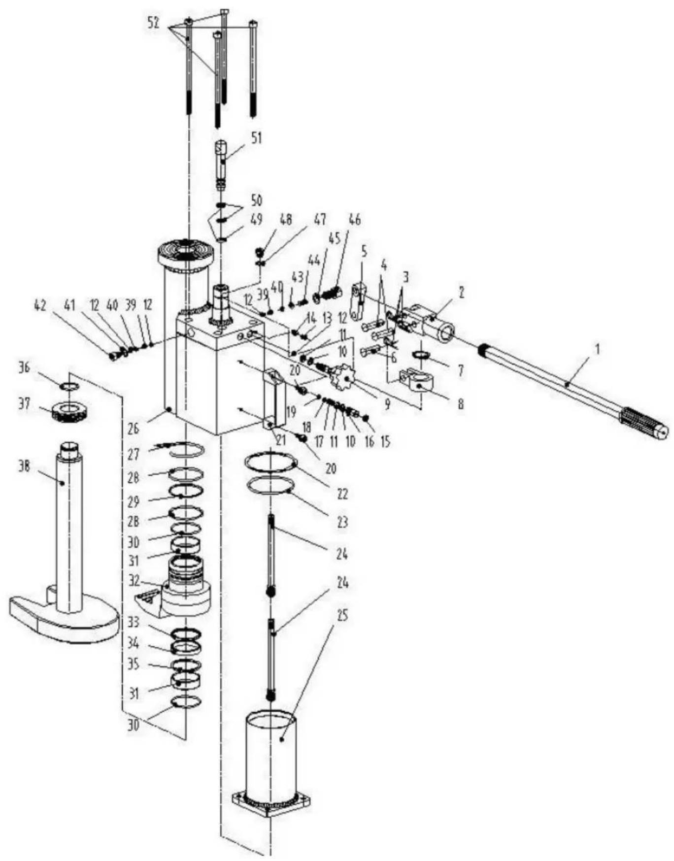
PART LIST
| NO. | Drawing No | Product Name | Assembly quantity | material | specifications |
| 1 | 100A-00000-01 | Handle Bar Set | 1 | Q235A | D21.3*500 |
| 2 | 100A-00000-02 | Handle socket | 1 | QT400-15 | M21*1.5 |
| 3 | 100A-00000-03 | R-Pin | 3 | 25Mn | D2.5*25 |
| 4 | 100A-00000-04 | Snapper Pin | 2 | Q235A | D10*40 |
| 5 | 100A-00000-05 | Clip Handle Rod | 1 | QT400-15 | D10 |
| 6 | 100A-00000-06 | Clip Pins | 1 | Q235A | D10*35 |
| 7 | 100A-00000-07 | Snap Ring | 1 | 65Mn | D26 |
| 8 | 100A-00000-08 | Snapper Bushing | 1 | ZG350 | D26*d10 |
| 9 | 100A-00000-09 | Pressure Relief Valve | 1 | 45# | M10*1 |
| 10 | 100A-00000-10 | back-up ring | 2 | NL1010 | D11*7*1.25 |
| 11 | 100A-00000-11 | O-ring | 2 | NBR70 | D6.5*2.65 |
| 12 | 100A-00000-12 | D6 Steel Ball | 4 | GCr15 | D6 |
| 13 | 100A-00000-13 | flush bolt | 1 | 25# | M4*8 |
| 14 | 100A-00000-14 | Limit retaining ring | 1 | Q235A | D4*1.5 |
| 15 | 100A-00000-15 | Decorative hat | 1 | PA6 | D10.8*1 |
| 16 | 100A-00000-16 | Relief valve spool | 1 | 45# | M10*1*18 |
| 17 | 100A-00000-17 | Relief valve spring | 1 | 65Mn | D7.8*15 |
| 18 | 100A-00000-18 | Spring seat | 1 | Q235A | D7.5*3 |
| 19 | 100A-00000-19 | D3.5 steel ball | 1 | GCr15 | D3.5 |
| 20 | 100A-00000-20 | Hexagon socket bolt | 2 | 25# | M6*16 |
| 21 | 100A-00000-21 | Aluminum handle | 1 | ZL01 | M6 |
| 22 | 100A-00000-22 | Sealing flat gasket | 1 | NL1010 | D91*d85*1.5 |
| 23 | 100A-00000-23 | O-ring | 1 | NBR70 | D74*3.55 |
| 24 | 100A-00000-24 | Oil suction tube assembly | 2 | 20# | M10*1 |
| 25 | 100A-00000-25 | Oil storage tank | 1 | Q235A | 85*3 |
| 26 | 100A-00000-26 | valve body assembly | 1 | 45# | 76*8 |
| 27 | 100A-00000-27 | Stop ring | 1 | 65Mn | D4*185 |
| 28 | 100A-00000-28 | O-ring | 2 | NBR70 | D54*3.1 |
| 29 | 100A-00000-29 | back-up ring | 1 | PTFE | D59.9*d55.1*2 |
| 30 | 100A-00000-30 | Stopping ring for holes | 2 | 65Mn | D50 |
| 31 | 100A-00000-31 | Oil free bearing | 2 | HMn58-2 | D50*d45*15 |
| 32 | 100A-00000-32 | Toe | 1 | 45# | D45*115 |
| 33 | 100A-00000-33 | Shaft seal | 1 | PTFE+NBR70 | D52*3*d45*3.2 |
| 34 | 100A-00000-34 | Y-Seal | 1 | PU | D53*d45*6 |
| 35 | 100A-00000-35 | back-up ring | 1 | PTFE | D52.9*d45.1*2 |
| 36 | 100A-00000-36 | Shaft stop ring | 1 | 65Mn | D30 |
| 37 | 100A-00000-37 | Piston | 1 | QT450-10 | D59.5*15 |
| 38 | 100A-00000-38 | ROD AS-PISTON | 1 | 45# | D45*340 |
| 39 | 100A-00000-39 | Spring | 2 | swrh67b | D4*0.5*8 |
| 40 | 100A-00000-40 | Spring seat | 2 | Q235A | D5*5 |
| 41 | 100A-00000-41 | Sealing copper gasket | 1 | H70 | D14*d10*1 |
| 42 | 100A-00000-42 | High pressure sealing oil bolt | 1 | 45# | M10*1.25*23 |
| 43 | 100A-00000-43 | D9 steel ball | 1 | GCr15 | D9 |
| 44 | 100A-00000-44 | Spring | 1 | 25Mn | D8*0.5*15 |
| 45 | 100A-00000-45 | Sealing iron pad | 1 | A3 | D18*d12*1 |
| 46 | 100A-00000-46 | High pressure sealing oil bolt | 1 | 45# | M12*1.5*25 |
| 47 | 100A-00000-47 | ED washer | 1 | NBR70 | M10 |
| 48 | 100A-00000-48 | Oil port plug | 1 | 45# | M10*1 |
| 49 | 100A-00000-49 | O-ring | 2 | NBR70 | D9.5*2.65 |
| 50 | 100A-00000-50 | back-up ring | 2 | PTFE | D10*d14*1.5 |
| 51 | 100A-00000-51 | piston | 1 | 45# | D14*85 |
| 52 | 100A-00000-52 | Hexagon socket bolt | 4 | 20# | M8*170 |
SECURITY & WARNINGS
1. Warning in advance
1.1 This jack shall be operated, maintained, and repaired only by qualified personnel.
1.2 The use of this jack should follow every important point described in this manual; otherwise, the injury of the operator or damage to articles might be caused because of neglect during the use of this jack.
1.3 Before the operation, the operator should check and confirm that the jack is in a good state.
1.4 The original manufacturer has no responsibility for the change of the jack's mechanical
property caused by the maintenance of the third party without any written permission from
the manufacturer except for repair by the manufacturer or his agency.
1.5 Limitation of Application:
Operation in severe conditions (e.g., extreme climates, freezer application, strong magnetic fields).
Operation subject to special rules (e.g. potentially explosive atmospheres, mines), Handling of loads, the nature of which could lead to dangerous situations (e.g. molten metal, acids, radiating materials, especially brittle loads),
Operation on sea ships.
Direct contact with foodstuffs.
2. Transportation & Storage
2.1 Transportation
The operating handle (02) is just for operating the jack. When transporting the jack, it can not be dropped or thrown because it may cause the piston to be damaged, and the pump might be spoiled. Therefore, the jack should be fixed before transporting it to avoid being shocked by other objects.
2.2 Storage
Keep the folded jack in a dry place.
The operator should watch the jack and the weight during all movements.
3.1 Scope of use
When using this jack, it shall be put on a fixed and solid place, such as a reinforced concrete floor, to lift or to move load vertically or horizontally in the workshop. In order to lift load in such a limited area of jack, some auxiliary pad can be placed under the base of it. The tooth plate (50) of the jack should be put on the base so
that it can be folded inside when retracting the jack. Use the jack only for and lowering of the load. Permanent holding of the load may overload the appliance and cause damage to persons and properties.
3.2 Method of operating
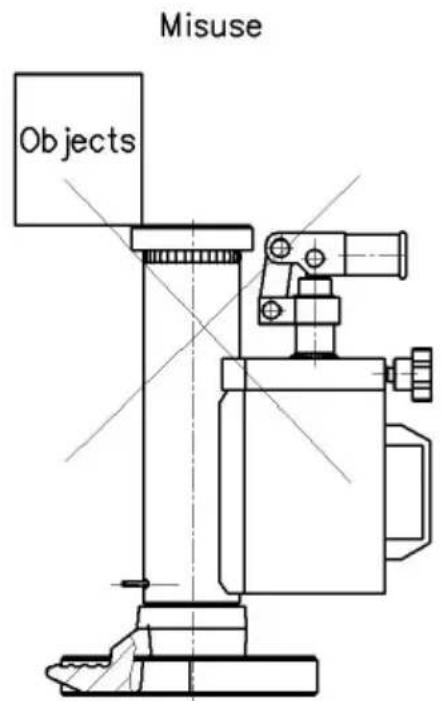
Put a weight on the tooth plate of jack stably.
Attention: Do not use the front end of the tooth plate to lift the weight.
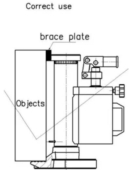
Important point: When lifting the weight by the tooth plate, the weight should close to the head of the jack to avoid the pillar (55) of the jack being bent. Please screw in the unloaded handle (22) tightly in a clockwise direction before lifting.
Then, press and lift the operating handle up and down repeatedly to pump pressure to lift the weight. The lifting movement can be stopped immediately stopping the lifting operation.
3.2.2 Reducing
Please screw out the unload handle slowly in an anti-clockwise direction to reduce the weight step by step. But when screwing up the round unload handle again reducing movement can be stopped instantly.
Note: When the jack is in unloaded condition, the head of it should be present reduce its height.
Attention: If the jack is not in a state of maintenance, each part of it can dismantled except the operating handle.
3.3 Safety Standard
3.3.1 The lifting of weight is a dangerous operation; the appointed operators should be professional, trained, and experienced.
3.3.2 Those extra weights can not be added to the lifted weight to avoid dr accidents.
3.3.3 Never exceed the recommended maximum limitation of lifting weight.
3.3.4 Please keep a safe distance with the lifted weight.
3.3.5 Never use the jack being changed or, spoilt or in bad condition itself.
3.3.6 When lifting the weight by tooth plate, please keep the weight close to head of the jack to avoid the pillar of the jack being bent. Please check th again.
3.3.7 Please confirm that each support point of ground should be solid and including floor area and loading, etc., and then any type of operating should handled on the plane surface only.
3.3.8 Please guarantee the lifted weight stability during the whole lifting period avoid it being turned over or being slipped. Each device shall be fixed before lifting.
3.3.9 Never operate the jack when people are standing on the lifting weight.
3.3.10 Never use the front and/or the tooth plate to lift weight. The tooth plate
should be located in its base totally, and the pushing point to the weight sh close to the back end of the tooth plate as far as possible.
3.3.11 Never screw the adjustable screw (26) under any circumstance. Otherw a typical accident of jack-dropping might happen. These parts (26,27, 28, 29, are the device of overloading protection.
3.3.12 Never use the side of the jack's head to lift the weight. The weight in contact with the black shadow surface of the following pictures.
3.3.13 Never work under the raised load.
3.3.14 The owner of the jack should guarantee all of the labels concerning standards. Keeping on its relative locations, which should be replaced when the can not be read clearly.
3.3.15 This operation manual can not cover all situations; please follow each of it cautiously.
4. Maintaining
Maintenance and repair need to be performed in accordance with the instructi No modification is allowed. When moving part is out of order, or there is oil during use- secure the load safely first, then contact service immediately. Lifetime of the jack: 2 years for non-frequent use.
6.1 Routine inspection
6.1.1 Before the operation, please inspect and confirm the following:
(1) All of the stoppers and screws of the jack have been screwed up tightly.
(2) There is no oil leaking on the jack's pump.
(3) There is no cracking or deformation on the pump body, tooth plate, or b
(4) The pump should be operated normally without load.
6.1.2 Under the frequent use of the jack, the time of checking shall be shot as well, and the following checking points shall be emphasized:
(1) All of the jack stoppers, screws, and nuts should be screwed up sufficient should be adjusted when it is necessary.
(2) When the jack is in a loading state, please pump it totally until the rele opens and without any oil-leaking (but the oil spot on the surface of the pill valve stem is normal).
Please release the pressure of the pump and check the pillar to confirm that flat and vertical without any shock and scraping. If any damage is found, the should be changed in time.
When the jack is reducing, the operator should check whether the reducing movement is stable or not, and it should be wedged (some slight vibration is normal).
Please carefully check all the exterior parts of the jack, including,
Pump body: no deformation, cracking, and impacting on it
-Operating hand space in each plug, the old plug shall be replaced by a new Tooth plate: no deformation & cracking
- Base: no deformation & cracking
5. Add oil
If the jack can not be pumped up to its rated height, it is necessary for your hydraulic oil to the tank. The hydraulic oil to be used must be iSO VG 15. Mixing of different fluids is prohibited!
6. Trouble shooting guide
| Symptom | Possible Cause | Solutions |
| Jack can not be pumped up properly. | The release valve not closed. | 1. Screw in the unloaded handle(22) tightly in clockwise direction.2. Lose the screw (15) to release the air from the pu and then screw in it tightly |
| Jack can not be released down at the top position | The release valve not opened enough | Screw out the unload handl (22) in counter-clockwise direction. |
| Jack can not pumped up to its rated max height | Oil is not enough. | Screw out the screw (24), add enough hydraulic oil. |
| The oil has leaked, around the plunger | Seals are worn ou | Replace worn seals with ne ones (9) and (1 0 ) by th specially appointed service centre. |
Address: Baoshanqu Shuangchenglu 803long 11hao 1602A-1609shi Shanghai
Imported to AUS: SIHAO PTY LTD. 1 ROKEVA STREETEASTWOOD NSW 2122 Australia
Imported to USA: Sanven Technology Ltd. Suite 250, 9166 Anaheim Place, Rancho Cucamonga, CA 91730
| UK | REP |
Pooledas Group Ltd
Unit 5 Albert Edward House, The Pavilion
Preston, United Kingdom
| EC | REP |
SHUNSHUN GmbH
Römeräcker 9 Z2021, 76351
Technical Support and E-Warranty Certificate www.vevor.com/support
VEVOR®
TOUGH TOOLS, HALF PRICE
natural_image
3D rendering of an orange cylindrical mechanical device with black base and lever, no visible text or symbolsBESOIN D'AIDE? CONTACTEZ-NOUS!
SÉCURITÉ ET AVERTISSEMENTS
natural_image
3D rendering of an orange cylindrical mechanical device with black base and lever, no visible text or symbolsBRAUCHEN SIE HILFE? KONTAKTIERE UNS!
natural_image
3D rendering of an orange cylindrical mechanical device with black base and lever, no visible text or symbolsHO BISOGNO DI AIUTO? CONTATTACI!
SICUREZZA E AVVERTENZE
Importato in AUS: SIHAO PTY LTD. 1 ROKEVA STREETEASTWOOD NSW 2122 Australia
Anaheim Place, Rancho Cucamonga, CA 91730
| REP. DEL | REGNO UNITO |
Gruppo Pooledas Ltd
natural_image
3D rendering of a mechanical device with orange cylindrical body, black base, and lever handle (no text or symbols visible)natural_image
3D rendering of an orange cylindrical mechanical device with black base and lever, no visible text or symbolsPOTRZEBUJE POMOCY? SKONTAKTUJ SIĘ Z NAMI!
www.vevor.com/support
VEVOR®
TOUGH TOOLS, HALF PRICE
Technische ondersteuning en e-garantiecertificaat www.vevor.com/support
TOE JACK
MODEL:108A-0050-00-00
natural_image
3D rendering of an orange cylindrical mechanical device with black base and lever, no visible text or symbolsHULP NODIG? NEEM CONTACT MET ONS OP!
VEILIGHEID & WAARSCHUWINGEN
natural_image
3D rendering of an orange cylindrical mechanical device with black base and lever, no visible text or symbolsBEHÖVS HJÄLP? KONTAKTA OSS!
SÄKERHET OCH VARNINGAR
1. Varning i förväg
Enhet 5 Albert Edward House, The Pavilions