DB18V-821 - Plane Vevor - Free user manual and instructions
Find the device manual for free DB18V-821 Vevor in PDF.

| Brand | Vevor |
| Model | DB18V-821 |
| Product type | Cordless Planer |
| Rated voltage | 18 V |
| No-load speed | 16000 /min |
| Max planing width | 82 mm |
| Max planing depth | 2 mm |
| Max rabbet depth | 8 mm |
| Motor type | Brushless |
| Net weight | 2.5 kg |
| Power supply | 18 V lithium-ion battery (not included) |
| Dust bag capacity | Empty frequently |
| Vacuum connection | Yes, 1-1/4 in outlet |
| Edge guide | Included, adjustable |
| Depth guide | Included |
| Blade wrench | Included |
| Reversible blades | Yes, 2 reversible blades |
| Rest stand | Yes, automatic retractable |
| Safety features | Trigger lock, eye and ear protection recommended |
| Maintenance | Clean exhaust port, empty dust bag, replace belt if necessary |
Frequently Asked Questions - DB18V-821 Vevor
User questions about DB18V-821 Vevor
0 question about this device. Answer the ones you know or ask your own.
Ask a new question about this device
Download the instructions for your Plane in PDF format for free! Find your manual DB18V-821 - Vevor and take your electronic device back in hand. On this page are published all the documents necessary for the use of your device. DB18V-821 by Vevor.
USER MANUAL DB18V-821 Vevor
Technical Support and E-Warranty Certificate www.vevor.com/support
PLANER
MODEL:DB18V-821
We continue to be committed to provide you tools with competitive price. "Save Half", "Half Price" or any other similar expressions used by us only represents an estimate of savings you might benefit from buying certain tools with us compared to the major top brands and does not necessarily mean to cover all categories of tools offered by us. I are kindly reminded to verify carefully when you are placing an order with us if you are actually saving half in comparison with the top major brands.
MODEL:DB18V-821
natural_image
Line drawing of a vintage digital camera with no visible text or symbolsWARNING: To reduce the risk of injury, the user must read and understand the operator's manualbefore using this product.
NEED HELP? CONTACT US!
Have product questions? Need technical support? Please feel free to contact us:
Technical Support and E-Warranty Certificate www.vevor.com/support
This is the original instruction, please read all manual instructions carefully before operating. VEVOR reserves a clear interpretation of o user manual. The appearance of the product shall be subject to the product you received. Please forgive us that we won't inform you ag there are any technology or software updates on our product.
TABLE OF CONTENTS
※General Power Tool Safety Warnings....03
※Planer Safety Warnings....06
※Symbols....08
※Features....10
※Assembly....10
※Operation....11
※Accessories....26

WARNING
Read all safety warnings and all instructions. Failure to follow the wa and instructions may result in electric shock, fire and/or serious injury.
Save all warnings and instructions for future reference.
The term "power tool" in the warnings refers to your mains-operated (corded) power tool or battery-operated (cordless) power tool.
WORK AREA SAFETY
- Keep work area clean and well lit. Cluttered or dark areas invite accidents.
■ Do not operate power tools in explosive atmospheres, such as in the presence of flammable liquids, gases or dust. Power tools create sp that may ignite the dust or fumes. - Keep children and bystanders away while operating a power tool. Distractions can cause you to lose control.
ELECTRICAL SAFETY
■ Power tool plugs must match the outlet. Never modify the plug in Do not use any adapter plugs with earthed (grounded) power tools. Unmodified plugs and matching outlets will reduce risk of electric sh
■ Avoid body contact with earthed or grounded surfaces such as pipe radiators, ranges and refrigerators. There is an increased risk of ele shock if your body is earthed or grounded.
■ Do not expose power tools to rain or wet conditions. Water entering power tool will increase the risk of electric shock.
■ Do not abuse the cord. Never use the cord for carrying, pulling or unplugging the power tool. Keep cord away from heat, oil, sharp end or moving parts. Damaged or entangled cords increase the risk of electric shock.
■ When operating a power tool outdoors, use an extension cord suitable for outdoor use. Use of a cord suitable for outdoor use reduces the use of electric shock.
■ If operating a power tool in a damp location is unavoidable, use a fault circuit interrupter (GFCI)protected supply. Use of a GFCI reduces the risk of electric shock.
■ Use this product only with batteries and chargers listed in tool/ app battery pack/ charger correlation supplement 987000-432.
PERSONAL SAFETY
■ Stay alert, watch what you are doing and use common sense when operating a power tool. Do not use a power tool while you are tir under the influence of drugs, alcohol or medication. A moment of inattention while operating power tools may result in serious personal injury.
■ Use personal protective equipment. Always wear eye protection. Protective equipment such as dust mask, non-skid safety shoes, hard or hearing protection used for appropriate conditions will reduce personal injuries.
■ Prevent unintentional starting. Ensure the switch is in the off-position before connecting to power source and/or battery pack, picking up or carrying the tool.
Carrying power tools with your finger on the switch or energizing p tools that have the switch on invites accidents.
■ Remove any adjusting key or wrench before turning the power tool wrench or a key left attached to a rotating part of the power tool result in personal injury.
■ Do not overreach. Keep proper footing and balance at all times. T enables better control of the power tool in unexpected situations.
■ Dress properly. Do not wear loose clothing or jewellery. Keep your clothing and gloves away from moving parts. Loose clothes, jeweller, long hair can be caught in moving parts.
■ If devices are provided for the connection of dust extraction and
collection facilities, ensure these are connected and properly used. L of dust collection can reduce dust-related hazards.
■ Do not wear loose clothing or jewelry. Contain long hair. Loose clery, or long hair can be drawn into air vents.
■ Do not use a ladder or unstable support. Stable footing on a solid enables better control of the power tool in unexpected situations.
POWER TOOL USE AND CARE
■ Do not force the power tool. Use the correct power tool for your application. The correct power tool will do the job better and safer rate for which it was designed.
■ Do not use the power tool if the switch does not turn on and of power tool that cannot be controlled with the switch is dangerous a must be repaired.
■ Disconnect the plug from the power source and/or the battery pack the power tool before making any adjustments, changing accessories or storing power tools. Such preventive safety measures reduce the of starting the power tool accidentally.
■ Store idle power tools out of the reach of children and do not all persons unfamiliar with the power tool or these instructions to operate the power tool. Power tools are dangerous in the hands of untrained users.
■ Maintain power tools. Check for misalignment or binding of moving breakage of parts and any other condition that may affect the power tool's operation. If damaged, have the power tool repaired before use. Many accidents are caused by poorly maintained power tools.
- Keep cutting tools sharp and clean. Properly maintained cutting tool with sharp cutting edges are less likely to bind and are easier to
■ Use the power tool, accessories, tool bits, etc., in accordance with instructions, taking into account the working conditions and the work be performed. Use of the power tool for operations different from the intended could result in a hazardous situation.
BATTERY TOOL USE AND CARE
■ Recharge only with the charger specified by the manufacturer. A cl that is suitable for one type of battery pack may create a risk of used with another battery pack.
■ Use power tools only with specifically designated battery packs. Use any other battery packs may create a risk of injury and fire.
■ When battery pack is not in use, keep it away from other metal like paper clips, coins, keys, nails, screws or other small metal objects that can make a connection from one terminal to another. Shorting battery terminals together may cause burns or a fire.
■ Under abusive conditions, liquid may be ejected from the battery; a contact. If contact accidentally occurs, flush with water. If liquid contacts eyes, additionally seek medical help. Liquid ejected from the battery cause irritation or burns.
SERVICE
■ Have your power tool serviced by a qualified repair person using identical replacement parts. This will ensure that the safety of the tool is maintained.
■ When servicing a power tool, use only identical replacement parts. Follow instructions in the Maintenance section of this manual. Use of unauthorized parts or failure to follow Maintenance instructions may create a risk of shock or injury.
PLANER SAFETY WARNINGS
■ Wait for the cutter to stop before setting the tool down. An exposed rotating cutter may engage the surface leading to possible loss of and serious injury.
■ Use clamps or another practical way to secure and support the workpiece to a stable platform. Holding the work by hand or against body leaves it unstable and may lead to loss of control.
■ Hold the power tool by insulated gripping surfaces only.
■ Know your power tool. Read operator's manual carefully. Learn its applications and limitations, as well as the specific potential hazards related to this power tool. Following this rule will reduce the risk of electric shock, fire, or serious injury.
■ Always wear eye protection with side shields marked to comply with ANSI Z87.1. Following this rule will reduce the risk of serious person injury.
■ Protect your lungs. Wear a face or dust mask if the operation is Following this rule will reduce the risk of serious personal injury.
■ Protect your hearing. Wear hearing protection during extended period operation. Following this rule will reduce the risk of serious personal injury.
■ Battery tools do not have to be plugged into an electrical outlet; they are always in operating condition. Be aware of possible hazard when not using your battery tool or when changing accessories. Following this rule will reduce the risk of electric shock, fire, or serial personal injury.
■ Do not place battery tools or their batteries near fire or heat. This reduce the risk of explosion and possibly injury.
■ Do not crush, drop or damage battery pack. Do not use a battery charger that has been dropped or received a sharp blow. A damage battery is subject to explosion. Properly dispose of a dropped or damaged battery immediately.
■ Batteries can explode in the presence of a source of ignition, such pilot light. To reduce the risk of serious personal injury, never use cordless product in the presence of open flame. An exploded batter propel debris and chemicals. If exposed, flush with water immediately
■ Do not charge battery tool in a damp or wet location. Do not use charge battery packs or products in locations where the temperature less than 50° For more than 100°F. Do not store outside or in ve
■ Under extreme usage or temperature conditions, battery leakage may occur. If liquid comes in contact with your skin, wash immediately with soap and water. If liquid gets into your eyes, flush them with clean for at least 10 minutes, then seek immediate medical attention. Follow
this rule will reduce the risk of serious personal injury.
■ Save these instructions. Refer to them frequently and use them to instruct others who may use this tool. If you loan someone this tool, them these instructions also.
SYMBOLS
The following signal words and meanings are intended to explain the of risk associated with this product.
| SYMBOL | SIGNAL | MEANING | |
 | DANGER | Indicates a hazardous situation, which, if not avoided,will result in death or serious injury | |
 | WARNING | Indicates a hazardous situation, which, if not avoided, could result in death or serious injury | |
 | CAUTION | Indicates a hazardous situation, which, if not avoided, could result in death or serious injury | |
| NOTICE: | (Without Safety Alert Symbol) Indicates informal considered important, but not related to a pote injury (e.g. messages relating to property dama | ||
| Some of the following symbols may be used on this product. Please and learn their meaning. Proper interpretation of these symbols will all operate the product better and safer. | |||
| SYMBOL | SIGNAL | MEANING | |
 | Safety Alert | Indicates a potential personal injury hazard | |
 | Read Operator's Manual | To reduce the risk of injury,user must rea understand operator's manual before using this product. | |
 | Eye Protection | Always wear eye protection with side shie marked to comply with ANSI Z87.1 | |
 | Ear Protection | Always wear ear protectors when using the product. | |
 | Wear dust masks | Always wear dust masks when using this product. | |
 | Wet Conditions Alert | Do not expose to rain or use in damp I | |
 | No Hands Symbol | Failure to keep your hands away from the blade will result in serious personal injury. | |
 | Recycle Symbol | This product uses lithium-ion (Li-ion)batterie Local, state or federal laws may prohibit disposal of batteries in ordinary trash. Cor your local waste authority for information regarding available recycling and/or disposa options. | |
 | Correct Disposal | This product is subject to the provision of European Directive 2012/19/EC. The symbol showing a wheelie bin crossed through indicates that the product requires separate refuse collection in the European Union. T applies to the product and all accessories marked with this symbol. Products marked such may not be discarded with normal domestic waste, but must be taken to a collection point for recycling electrical and electronic devices | |
 | FCC statement | This device complies with Part 15 of the Rules. Operation is subject to the following conditions:(1)This device may not cause harmful interference, and (2)this device must accept any interference received, including interference that may cause undesired operation. | |
| V | Volts | Voltage | |
| Hz | Hertz | Frequency (cycles per second) | |
| min | Minutes | Time | |
| no | No Load Speed | Rotational speed, at no load | |
| .../min | Per Minute | Revolutions, strokes, surface speed, orbits etc., per minute. | |
FEATURES
PRODUCT SPECIFICATIONS
| Model | DB18V-821 |
| Rated Voltage | 18V |
| No-load speed | 16000/min |
| Max planing width | 82 MM |
| Max planing depth | 2 MM |
| Max Rabbeting depth | 8 MM |
| Motor type | Brushless |
| Net weight | 2.5 KGS |
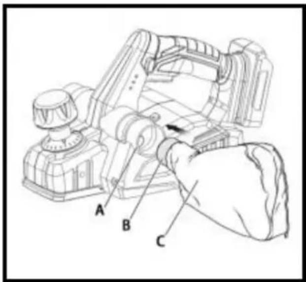
ASSEMBLY

WARNING:
Do not use this product if it is not completely assembled or if any appear to be missing or damaged. Use of a product that is not properly completely assembled or with damaged or missing parts could result in serious personal injury.

WARNING:
Do not attempt to modify this product or create accessories or attach not recommended for use with this product. Any such alteration or modification is misused and could result in a hazardous condition lead to possible serious personal injury.
OPERATION

WARNING:
Do not allow familiarity with tools to make you careless. Remember the careless fraction of a second is sufficient to inflict serious injury.

WARNING:
Always remove battery pack from the tool when you are assembling making adjustments, cleaning, or when not in use. Removing battery will prevent accidental starting that could cause serious personal injury

WARNING:
Always wear eye protection with side shields marked to comply with Z87.1. Failure to do so could result in objects being thrown into your resulting in possible serious injury.

WARNING:
Do not use any attachments or accessories not recommended by the manufacturer of this product. The use of attachments or accessories r recommended can result in serious personal injury.

Attention:
When planning too fast or too deep, it will cause equipment overload protection and shorten battery life. Please control the planning speed depth reasonably.
APPLICATIONS
You may use this tool for the purposes listed below:
■ Planing the edge of a wooden door or shelf
■ Planing the edge of a piece of lumber
■ Making rabbet cuts in wood
■ Chamfering sharp edges of lumber
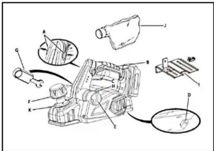
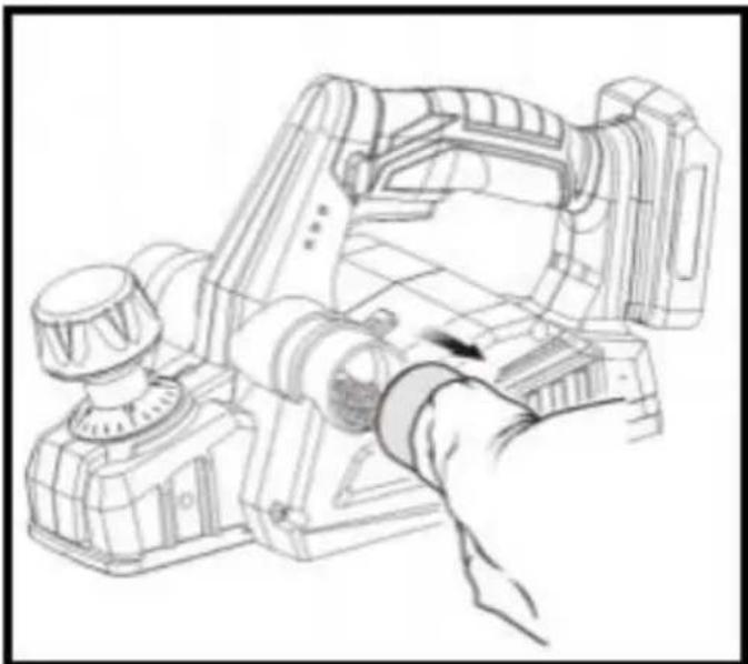
ADJUSTING THE EXHAUST DIRECTION

WARNING:
Collected dust from planing surface coatings such as polyurethanes, linseed oil, etc., can self-ignite in the planer dust bag or elsewhere a cause fire. To reduce the risk of fire, always empty the dust bag fire while planning. NEVER store or leave a planer without to tally empty dust bag. Also follow the recommendations of the coatings manufacture
Change the direction of the exhaust to either the right or left to con direction of debris when working in confined areas.
To adjust the exhaust direction and dust bag:
■ Remove the battery pack.
■ To adjust exhaust to the right: Move the exhaust direction lever sc arrow points right (the handle will point left). Install the dust bag right exhaust port.
■ To adjust exhaust to the left: Move the exhaust direction lever so arrow points left (the handle will point right). Install the dust bag c left exhaust port.
NOTE: Check that the dust bag is attached to the same port select the exhaust direction lever.
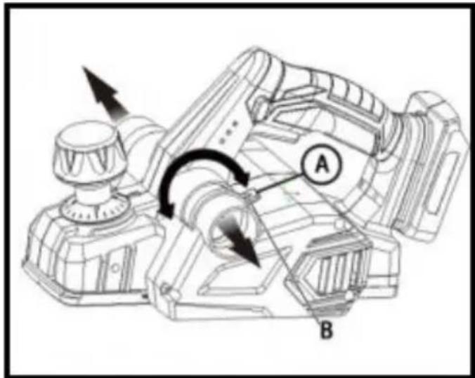
ATTACHING THE DUST BAG
■ Remove the battery pack.
■ Slide the collar of the dust bag onto the exhaust port.
NOTE: To remove the dust bag, pull it straight out of the exhaust p

NOTICE:
The dust bag fills quickly. Empty it often to prevent damage to the
ATTACHING THE PLANER TO A VACUUM
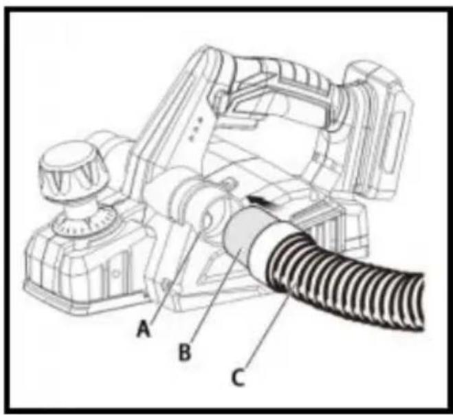
The chip collection system of the planer has a 1-1/4 in. port for insert vacuum hose.
■ Remove the battery pack. Remove the dust bag.
■ Attach a vacuum hose to the left or right chip exhaust.
■ Set exhaust direction lever to the selected exhaust port.
■ Connect the vacuum to a power supply.
■ Turn vacuum on before starting cut.

WARNING:
When the tool is not connected to vacuum, always reinstall the dust back onto the tool. Failure to do so could cause dust or foreign objects be thrown into your face or eyes, which could result in possible serious injury.
INSTALLING/REMOVING BATTERY PACK
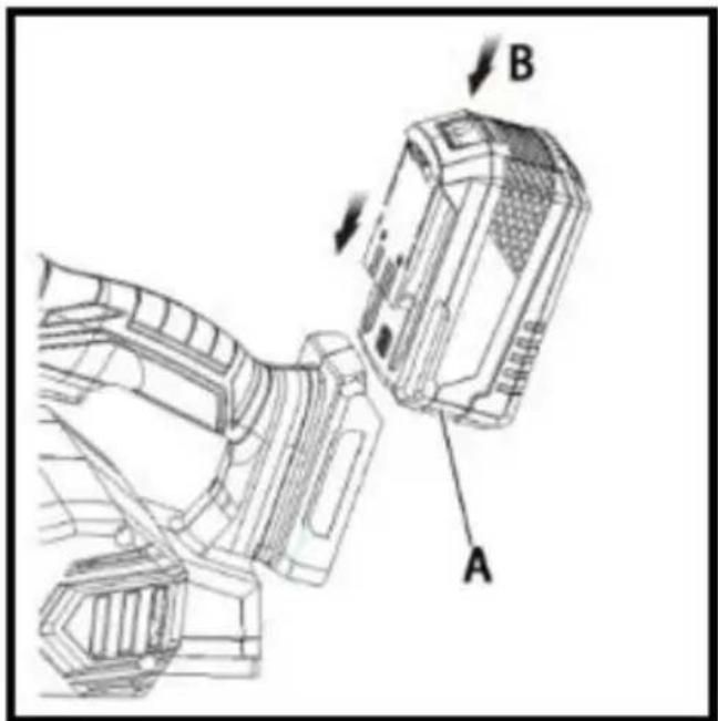
■ Lock the switch trigger.
■ Insert the battery pack into the product as shown.
■ Make sure the latches on each side of the battery pack snap into and the battery pack is secured in the product before beginning operation.
■ Depress the latches to remove the battery pack.
■ For complete charging instructions, see the operator's manuals for your battery pack and charger.
STARTING/STOPPING THE PLANER
■ To start the planer: Push the lock-off button from either side, and depress the switch trigger.
■ To stop the planer: Release the switch trigger.
KICKSTAND
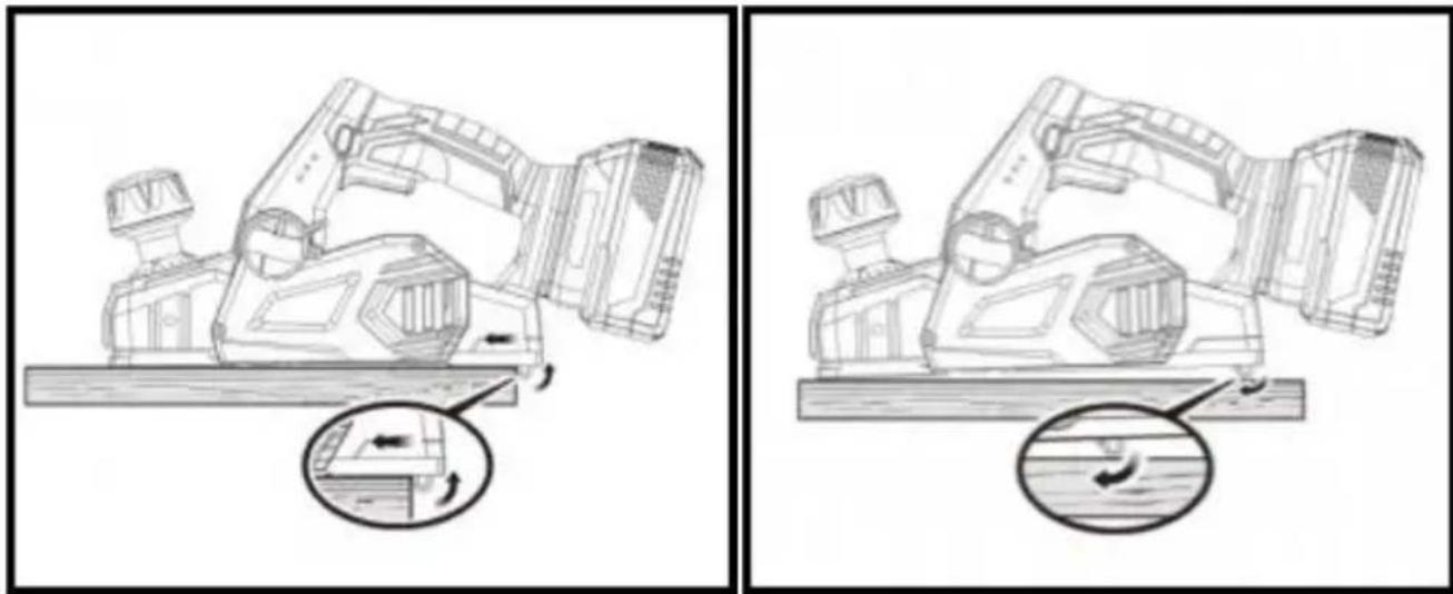
natural_image
Technical line drawings of a mechanical device with a close-up inset showing internal components (no text or symbols)The planer has been equipped with an automatic pivoting kickstand that will prevent the blades from contacting the workbench when not in us you begin the planning operation, the kickstand will automatically retract it passes over the edge of the workpiece. When setting the planer d the workbench, the kickstand will automatically pivot down to prevent blade from making any contact.

WARNING:
Make sure the kickstand operates freely at all times and that the are surrounding the kickstand is clear of debris.Failure to do so could res serious personal injury.
PLANING DEPTH
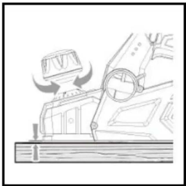
natural_image
Line drawing of a mechanical assembly with arrows indicating motion or force direction (no text or symbols)When you begin planning a rough piece of material, the planer will remove the high spots at first. Successive passes will remove more material. By removing no more than 1/64 in. with each pass, you achieve the smoothest finish, even from the roughest workpiece.
Always begin by making test cuts in scrap wood to make sure that planer is removing the desired amount of wood.
To set the planning depth:
■ Remove the battery pack.
■ Turn the depth adjustment knob clockwise to set the desired depth cut. The maximum depth of cut is 1/16 in.
NOTE: Use only detented depth settings. Attempting cuts with the dep cut settings between the detented positions can result in uneven cuts.
NOTE: To protect the blades during storage, transporting,etc., turn the depth adjustment knob counterclockwise top on the depth of cut scale park the blade.

WARNING:
Always clamp the workpiece securely before making a cut. Work mov during a cut could result in loss of control of the planer and cause
injury.
■ Clamp the work securely.
■ Be sure the material to be planned is free of nails, staples, or scre
■ Support the work so that the operation is on your side.
NOTICE:
Planing too fast results in a poor finish and increases chip build-up i chip exhaust. Chip build-up restricts airflow and can cause motor overheating.
WARNING:
Do not attempt to clear a blocked chip exhaust until the blades stop you have disconnected the product from the power source. Failure to this warning can result in serious personal injury.
PLANING
natural_image
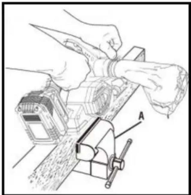
Technical line drawing of a hand operating a workbench with tools, labeled A (no text or symbols present)■ Clamp the work securely
■ Adjust the planing depth. Refer to Planing Depth earlier in this ma
■ Hold the depth adjustment knob with one hand and the handle with other hand.

WARNING:
Always use two hands on the tool for any operation; this assures that maintain control and avoid risk of serious personal injury. Always propose support and clamp the work so that both hands are free to control the planer.
Never operate the tool overhead or inverted from the proper operating position; serious personal injury may result.
■ Place the front shoe on the edge of work to be planned.
NOTE: Make sure the blades are not touching the work.
■ Apply pressure to the depth adjustment knob so that the front should completely flat on the work. Start the planer and let the motor re maximum speed.
■ Hold the planer firmly and push it forward into the work, using a sl steady motion. Plane slowly and empty the dust bag often.
■ Apply downward pressure toward the rear handle as your each the end of the planned cut. This helps keep the rear section of the base in contact with the work and prevents the front of the plane gouging the cut.

WARNING:
Be careful to avoid hitting nails or staples during planning operation; action could nick, crack, or damage blades.
NOTE: We suggest that you always keep an extra set of blades on As soon as the blades in the planer show signs of becoming dull, r them. The blades are reversible and can be reversed until both sides become dull.
CHAMFERING
The planer is designed with a chamfering groove in the front shoe to chamfer corners of boards as shown. Before making a cut on good
practice cutting on scrap lumber to determine the amount to be remo
■ Clamp the work securely.
■ Hold the depth adjustment knob with one hand and the handle with other hand.
■ Place the chamfering groove on the surface to be cut.
■ Start the planer and let the motor reach maximum speed.
■ Hold the planer firmly and push it forward into the work, using a steady motion.
■ Apply downward pressure to keep the planer flat at the beginning end of the work surface.
PLANING EDGES AND MAKING RABBET CUTS
The planer comes with an adjustable edge guide for precision edge p and rabbet cutting. Attach the edge guide to either side of the plane planing edges and attach the edge guide to the left side for making rabbet cuts.
ATTACHING THE EDGE GUIDE FOR PLANINGEDGES
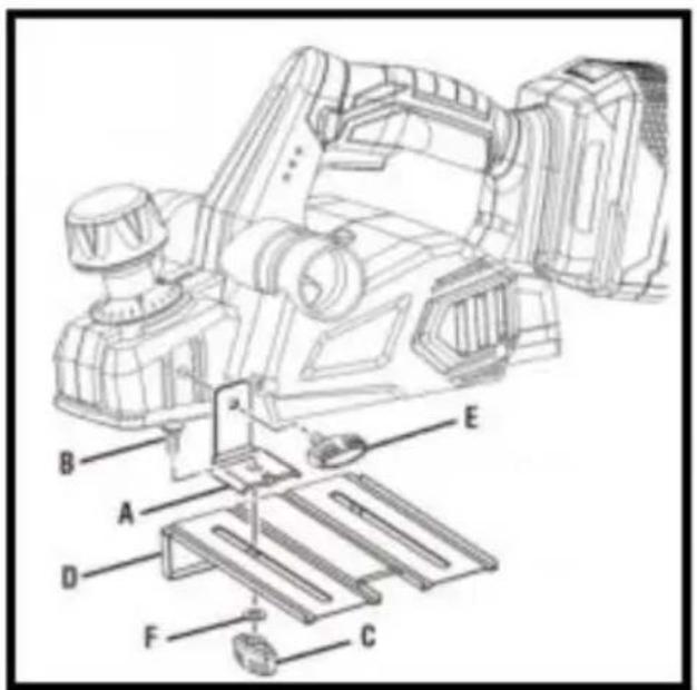
Remove the battery pack.
■ Attach the bracket to the desired side of the planer and tighten the bolt securely.
■ Attach the edge guide to the bracket using the knob nut and the head bolt.
■ Tighten the knob nut securely.
PLANING EDGES
Follow the directions in the Planning section earlier in this manual. H edge guide firmly against the edge of the work surface.
ATTACHING THE EDGE GUIDE FOR MAKING RABBET CUTS
■ Remove the battery pack.
■ Attach the bracket to the left side of the planer and tighten the k securely.
■ Attach the edge guide loosely to the bracket using the knob nut a carriage head bolt (do not tighten).
■ Adjust the edge guide to the desired width for the rabbet cut.
■ Tighten the knob nut securely.
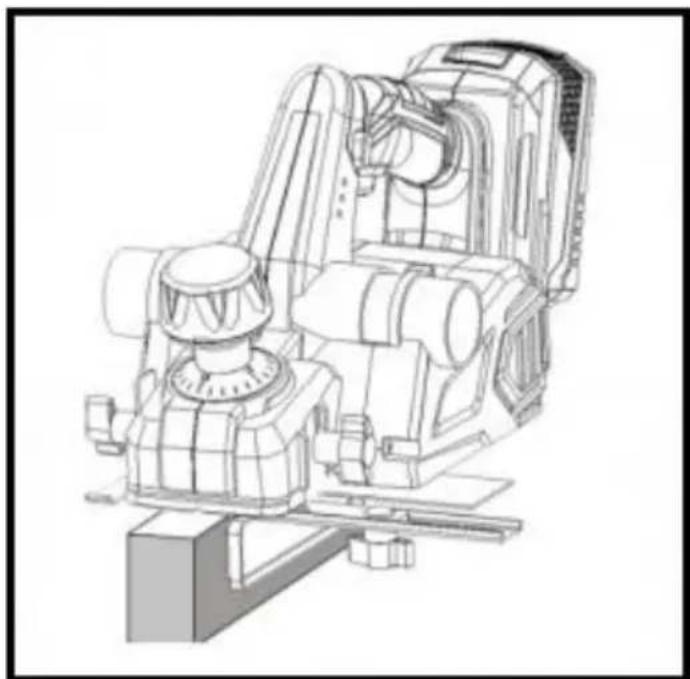
TO MAKE RABBET CUTS
natural_image
Technical line drawing of a mechanical assembly (no text or symbols visible)Follow the directions in the Planning section earlier in this manual. R edge guide firmly against the edge of the work surface.
The depth of the rabbet is determined by the depth of the cut and number of passes made along the work surface.
The maximum depth of the rabbit cut is 1/2 in. and has to be cut passes or less to reach the desired depth. The width of the rabbit adjustable by moving the edge guide.

WARNING:
When servicing, use only identical replacement parts. Use of any other parts may create a hazard or cause product damage.

WARNING:
Always wear eye protection with side shields marked to comply with Z87.1. Failure to do so could result in objects being thrown into your resulting in possible serious injury.
GENERAL MAINTENANCE
Avoid using solvents when cleaning plastic parts. Most plastics are susceptible to damage from various types of commercial solvents and be damaged by their use. Use clean cloths to remove dirt, dust, oil, etc.

WARNING:
Do not at any time let brake fluids, gasoline, petroleum based product penetrating oils, etc., come in contact with plastic parts. Chemicals ca damage, weaken or destroy plastic which may result in serious person injury.
Electric tools used on fiberglass material, wallboard, spackling compound or plaster are subject to accelerated wear and possible premature failure
because the fiberglass chips and grindings are highly abrasive to bear brushes, commutators, etc. Consequently, we do not recommend using this tool for extended work on these types of materials. However, if you work with any of these materials, it is extremely important to clean the using compressed air.
LUBRICATION
All of the bearings in this tool are lubricated with a sufficient amount grade lubricant for the life of the unit under normal operating condition. Therefore, no further lubrication is required.
CLEANING THE EXHAUST PORT AND EMPTYING THE DUST BAG
natural_image
Technical line drawing of a mechanical device with a hand operating the shaft (no text or symbols present)After using the planer for an extended period of time or when planin or green lumber, chips may build-up in the exhaust port and require cleaning. Chip build up restricts airflow and causes the motor to overheat. Clean the exhaust port and empty the dust bag regularly
■ Remove the battery pack.
■ Remove the dust bag from the exhaust port.
■ Clean the chip or dust build-up from the exhaust port of the plane a small piece of wood. Do not use your hands or fingers.
■ Empty all debris from the dust bag and ensure that the collar is debris.
■ Replace the dust bag.
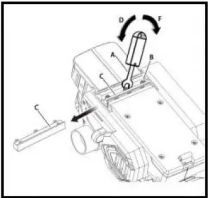
REPLACING BLADES
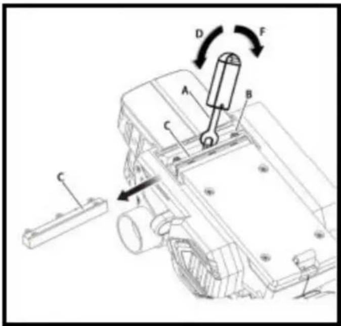
The planer blades are reversible. When one edge becomes dull, the can be reversed so that the other side can be used.
Always replace or reverse blades in pairs. Do not attempt to sharpen blades. If the blades in the planer show signs of becoming dull, chip damaged in any way, replace them.
When replacing the blades, use recommended replacement blade only,
! WARNING:
Always wear heavy leather gloves and use caution when loosening bls screws and handling and/or changing blades. Blades are sharp and cause serious personal injury.
■ Remove the battery pack.
- Secure the planer in an upside-down position.
■ Loosen the three screws securing the blade on the blade holder b turning counterclockwise with the provided blade wrench.
NOTE: Do not over-loosen the screws. If screws are too loose, align with the new blade will not be accurate.
NOTE: Before removing the old blades, take notice of the direction o as well as how the tapered edge of the old blades is oriented. The edge of the new blades must be in the same orientation as the orig blades, with the tapered edge on the same side as the screw heads the flat edge facing the cutter block.
■ Depress the spring-loaded blade guard.
■ Push the blade holder out of the cutter block assembly using the screwdriver.
■ Remove the old blade from the blade holder by sliding the blade using the tip of a screwdriver.
NOTE: If blade cannot be easily pushed out of blade holder after lock, blade securing screws, use a block of wood to break the blade loose the blade holder with a short sharp blow. Then push the blade with screwdriver to remove it. If necessary, tap the block of wood sharply small hammer to break the blade loose.
■ Clean any sawdust or wood chips from around the blade area.
■ Slide the new blade into the slot of the blade holder.
■ Use a screwdriver to push the blade into the blade holder until it centered into position.
■ Depress the spring-loaded blade guard.
■ Insert the blade holder into the cutter block assembly.
■ Retighten the three blade securing screws using the blade wrench.
■ Repeat the above procedure to change the other blade.
REPLACING THE BELT
When replacing the belt, use the recommended replacement belt only,
■ Remove the battery pack.
■ Remove belt cover screws.
■ Remove the belt cover.
■ Force the old belt from the small pulley by turning in the direction As you turn the belt, pull and work it off the small pulley until it completely removed from both pulleys.
■ Install the new belt over the small pulley, being sure to align the As you turn the belt, push and work it onto the large pulley until
place.
■ Replace the belt cover.
■ Install belt cover screws and tighten securely.
NOTE: Do not overtighten the screws.
ACCESSORIES
ACCESSORIES--BRUSHLESS PLANER WITH COLOR BOX
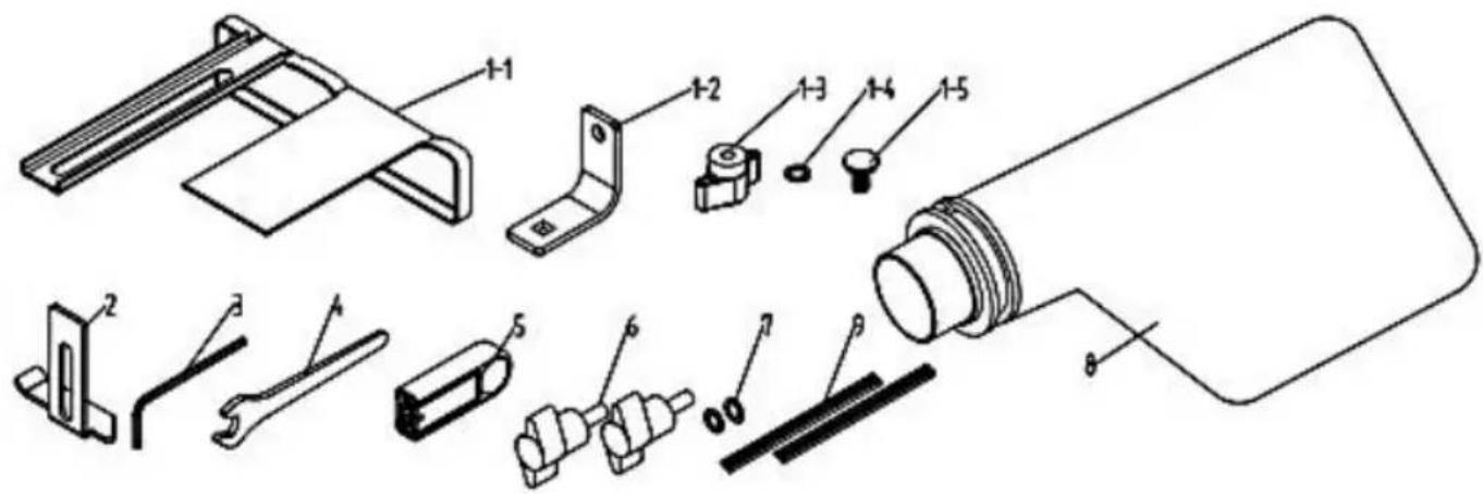
| PART NO. | DESCRIPTION | QTY |
| 1 | Parallel Guide | |
| 1-1 | Parallel Guide | 1 PC |
| 1-2 | Parallel Guider bracket | 1 PC |
| 1-3 | Butterfly nut | 1 PC |
| 1-4 | Flat washer | 1 PC |
| 1-5 | Square neck bolts | 1 PC |
| 2 | Depth Guide | 1 PC |
| 3 | Inner hex wrench | 1 PC |
| 4 | Spanner | 1 PC |
| 5 | Wrench cover | 1 PC |
| 6 | Butterfly screw | 2 PCS |
| 7 | Flat washer | 2 PCS |
| 8 | Dust bag | 1 PC |
| 9 | Blade | 1 SET |
ACCESSORIES--BRUSHLESS PLANER WITH BMC BOX

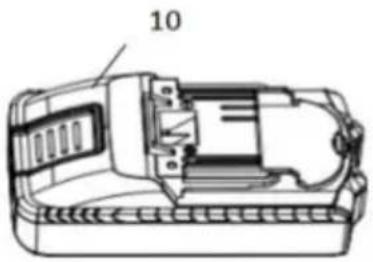

natural_image
Close-up of a black electronic device with wires and connectors, labeled with number 11 (no visible text or symbols on the device itself)| PART NO. | DESCRIPTION | QTY |
| 1 | Parallel Guide | |
| 1-1 | Parallel Guide | 1 PC |
| 1-2 | Parallel Guider bracket | 1 PC |
| 1-3 | Butterfly nut | 1 PC |
| 1-4 | Flat washer | 1 PC |
| 1-5 | Square neck bolts | 1 PC |
| 2 | Depth Guide | 1 PC |
| 3 | Inner hex wrench | 1 PC |
| 4 | Spanner | 1 PC |
| 5 | Wrench cover | 1 PC |
| 6 | Butterfly screw | 2 PCS |
| 7 | Flat washer | 2 PCS |
| 8 | Dust bag | 1 PC |
| 9 | Blade | 1 SET |
| 10 | Battery | 1 PC |
| 11 | changer | 1 PC |
DB18V-821
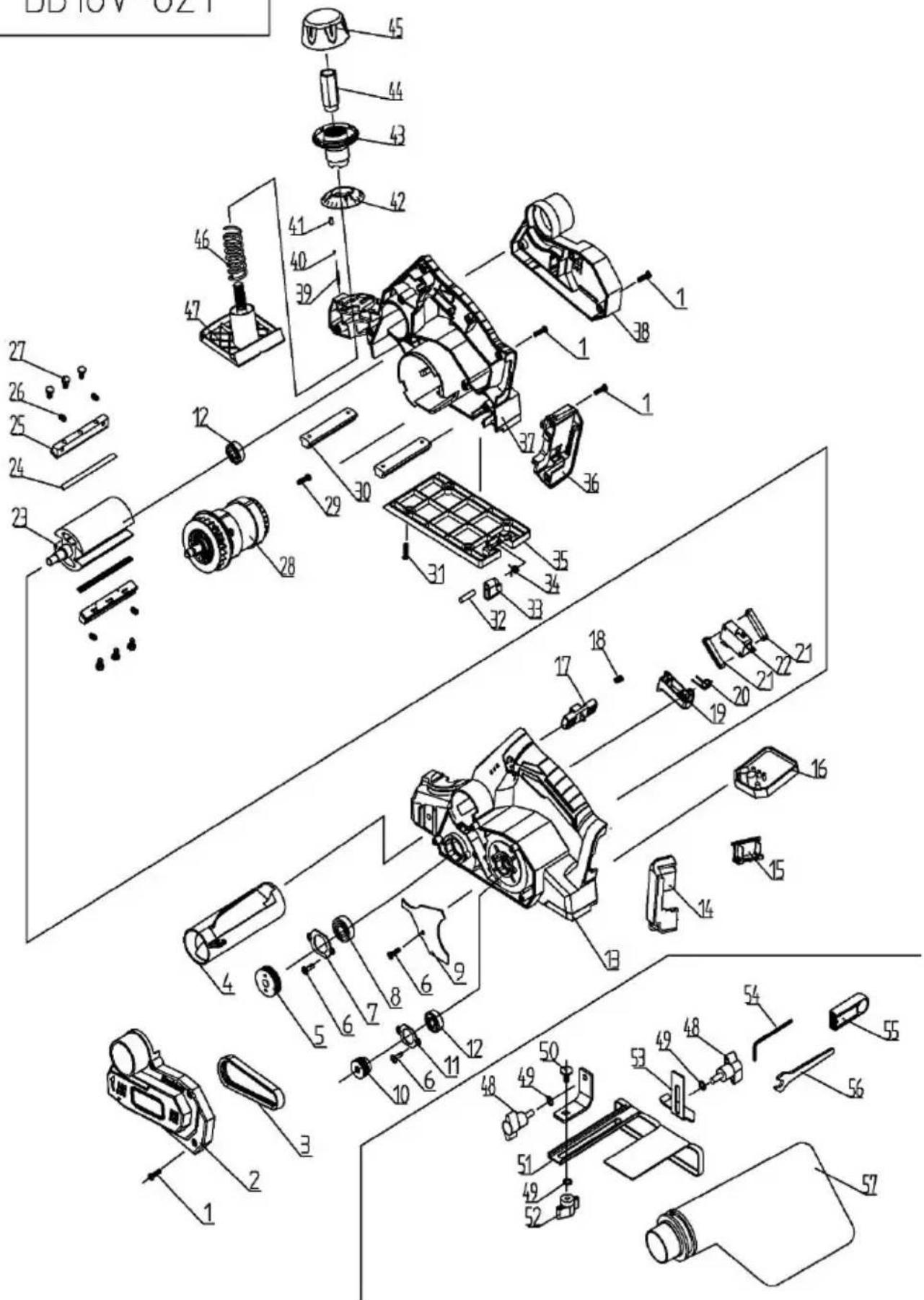
| DB18V-821B | |||||||
| NO. | DESCRIPTION | QTY | NO. | DESCRIPTION | QTY | ||
| 1 | TAPPING SCREW ST4*14 | 20 | PCS | 30 | SUPPORT BOARD | 2 | PCS |
| 2 | BELT COVER | 1 | PCS | 31 | TAPPING SCREW ST4*12 | 4 | PCS |
| 3 | BELT | 1 | PCS | 32 | CYLINDRICAL PIN 5*32 | 1 | PCS |
| 4 | DUST TUBE | 1 | PCS | 33 | PARK REST | 1 | PCS |
| 5 | V-PULLEY (BIG) | 1 | PCS | 34 | TORSION SPRING | 1 | PCS |
| 6 | TAPPING SCREW ST4X12 | 5 | PCS | 35 | BASE | 1 | PCS |
| 7 | BEARING COVER | 1 | PCS | 36 | BATTERY PIN COVER(2) | 1 | PCS |
| 8 | BALL BEARING 6000RS | 1 | PCS | 37 | RIGHT HOUSING | 1 | PCS |
| 9 | DUST BAFFLE | 1 | PCS | 38 | REAR COVER | 1 | PCS |
| 10 | V-PULLEY(SMALL) | 1 | PCS | 39 | TORSION SPRING | 1 | PCS |
| 11 | BEARING COVER | 1 | PCS | 40 | STEEL BALL 2.5 | 1 | PCS |
| 12 | BALL BEARING 608RS | 2 | PCS | 41 | BULLET | 1 | PCS |
| 13 | LEFT HOUSING | 1 | PCS | 42 | DEPTH SCALE | 1 | PCS |
| 14 | BATTERY PIN COVER(1) | 1 | PCS | 43 | KNOB | 1 | PCS |
| 15 | BATTERY PIN | 1 | PCS | 44 | ADJUST NUT | 1 | PCS |
| 16 | PCB CONTROL BOARD | 1 | PCS | 45 | KNOB COVER | 1 | PCS |
| 17 | LOCK-OFF BUTTON | 1 | PCS | 46 | ADJUSTMENT SPRING | 1 | PCS |
| 18 | SPRING | 1 | PCS | 47 | FRONT BASE | 1 | PCS |
| 19 | BUTTON OF SWITCH | 1 | PCS | 48 | BUTTERFLY SCREW | 2 | PCS |
| 20 | TORSION SPRING | 1 | PCS | 49 | FLAT WASHER 6 | 3 | PCS |
| 21 | SWITCH BASE | 2 | PCS | 50 | SQUARE NECK BOLT M6X12 | 1 | PCS |
| 22 | SWITCH | 1 | PCS | 51 | EDGE GUIDE | 1 | PCS |
| 23 | ROLLER | 1 | PCS | 52 | BUTTERFLY NUT | 1 | PCS |
| 24 | BLADE | 2 | PCS | 53 | DEPTH GUIDER | 1 | PCS |
| 25 | BLADE HOLDER | 2 | PCS | 54 | INTERNAL HEX. WRENCH | 1 | PCS |
| 26 | SCREW M5*10 | 4 | PCS | 55 | WRENCH STORAGE | 1 | PCS |
| 27 | HEX BOLT M5*8 | 6 | PCS | 56 | WRENCH | 1 | PCS |
| 28 | BRUSHLESS MOTOR | 1 | PCS | 57 | DUST BAG | 1 | PCS |
| 29 | TAPPING SCREW ST4*10 | 2 | PCS | ||||
Manufacturer: Shanghaimuxinmuyeyouxiangongsi
Address: Shuangchenglu 803nong11hao1602A-1609shi, baoshanqu, shanghai 200000 CN.
Imported to AUS: SIHAO PTY LTD, 1 ROKEVA STREETEASTWOOD NS 2122 Australia
Imported to USA: Sanven Technology Ltd., Suite 250, 9166 Anaheim Pla Rancho Cucamonga, CA 91730
| EC | REP |
E-CrossStu GmbH
Mainzer Landstr.69, 60329 Frankfurt am Ma
| UK | REP |
YH CONSULTING LIMITED.
C/O YH Consulting Limited Office 147, Centurion H London Road, Staines-upon-Thames, Surrey, TW18 4
VEVOR®
TOUGH TOOLS, HALF PRICE
Technical Support and E-Warranty Certificate www.vevor.com/support
VEVOR®
TOUGH TOOLS, HALF PRICE
natural_image
Line drawing of a vintage digital camera with no visible text or symbols
CARACTÉRISTIQUES DU PRODUIT
RÉGLAGE DE LA DIRECTION D'ÉCHAPPEMENT

AVERTISSEMENT:
natural_image
Technical line drawing of a mechanical device with an inset showing a close-up of the component (no text or symbols present)
natural_image
Technical line drawing of a mechanical device with a magnified inset showing a water surface feature (no text or symbols)natural_image
Technical line drawing of a mechanical assembly with no visible text or symbolsnatural_image
Technical line drawing of hands using a lathe tool on a workbench, with no visible text or symbolsnatural_image
Technical line drawing of a mechanical assembly (no text or symbols visible)natural_image
Technical line drawing of a mechanical device with a hand operating it (no text or symbols present)REEMPLACEMENT DES LAMES
C/O YH Consulting Limited Bureau 147, Centurion House, Route de Londres, Staines-upon-Thames, Surrey, TW18 4AX
VEVOR®
TOUGH TOOLS, HALF PRICE
natural_image
Line drawing of a vintage digital camera with control panel and lens (no text or symbols)
natural_image
Technical line drawing of a mechanical device with a magnified inset showing a close-up of the component (no text or symbols present)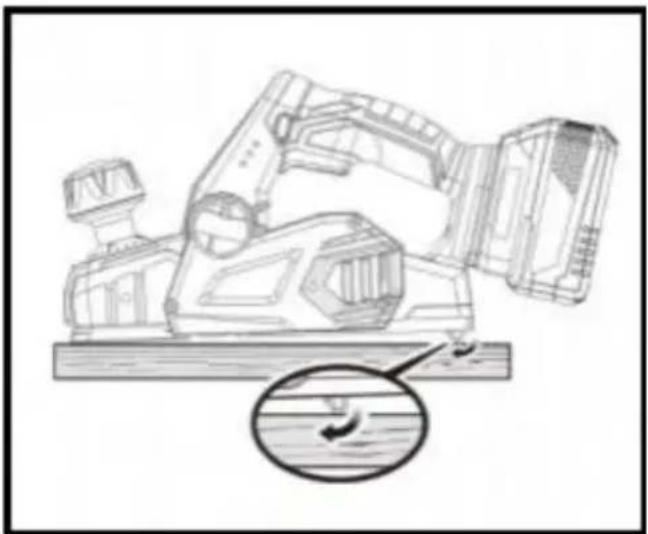
natural_image
Technical line drawing of a mechanical assembly with a magnified inset showing a water feature (no text or symbols)natural_image
Technical line drawing of a mechanical assembly with no visible text or symbolsnatural_image
Illustration of hands using a tool to work on a wooden object, with a vise and labeled component A (no text or symbols beyond labels)natural_image
Technical line drawing of a mechanical assembly (no text or symbols visible)natural_image
Technical line drawing of a mechanical device with a hand operating it (no text or symbols present)C/O YH Consulting Limited Office 147, Centurion House, London Road, Staines-upon-Thames, Surrey, TW18 4AX
VEVOR®
TOUGH TOOLS, HALF PRICE
natural_image
Line drawing of a vintage digital camera with control panel and lens (no text or symbols)
natural_image
Technical line drawing of a mechanical device with a magnified inset showing a close-up of the component (no text or symbols present)
natural_image
Technical line drawing of a mechanical assembly with a magnified inset showing a water feature (no text or symbols)natural_image
Technical line drawing of a mechanical assembly with no visible text or symbolsnatural_image
Illustration of hands using a tool to work on a wooden object, with a vise and labeled component A (no text or symbols beyond labels)natural_image
Technical line drawing of a mechanical assembly (no text or symbols visible)natural_image
Technical line drawing of a mechanical device with a hand operating it (no text or symbols present)Importato in AUS: SIHAO PTY LTD, 1 ROKEVA STREETEASTWOOD NSW 2122 Australia
Importato negli USA: Sanven Technology Ltd., Suite 250, 9166 Anaheim Place, Rancho Cucamonga, CA 91730
natural_image
Line drawing of a vintage digital camera with no visible text or symbols
natural_image
Technical line drawing of a mechanical device with a magnified inset showing a close-up of the component (no text or symbols present)
natural_image
Technical line drawing of a mechanical assembly with a magnified inset showing a water feature (no text or symbols)natural_image
Technical line drawing of a mechanical assembly with no visible text or symbolsnatural_image
Illustration of hands using a tool to work on a wooden object, with a vise and labeled component A (no text or symbols beyond labels)natural_image
Technical line drawing of a mechanical assembly (no text or symbols visible)natural_image
Technical line drawing of a mechanical device with a hand operating it (no text or symbols present)Importado a Australia: SIHAO PTY LTD, 1 ROKEVA STREETEASTWOOD NSW 2122 Australia
Importado a EE. UU.: Sanven Technology Ltd., Suite 250, 9166 Anaheim Place, Rancho Cucamonga, CA 91730

E-CrossStu GmbH
C/O YH Consulting Limited Oficina 147, Centurion House,
Carretera de Londres, Staines-upon-Thames, Surrey, TW18 4AX
VEVOR®
TOUGH TOOLS, HALF PRICE
natural_image
Line drawing of a vintage digital camera with no visible text or symbols
BEZPIECZEŃSTWO W MIEJSCU PRACY
REGULACJA KIERUNKU WYDECHU

OSTRZEŻENIE:
natural_image
Technical line drawing of a mechanical device with a magnified inset showing a close-up of the component (no text or symbols present)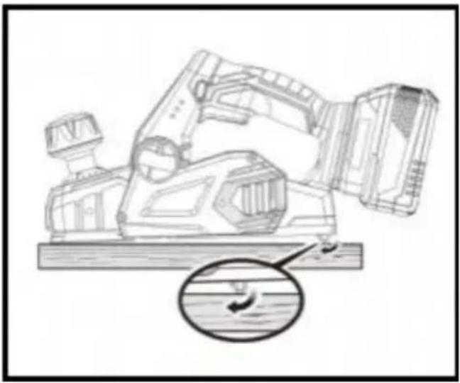
natural_image
Technical line drawing of a mechanical device with a magnified inset showing a curved component (no text or symbols)natural_image
Technical line drawing of a mechanical assembly with no visible text or symbolsnatural_image
Technical line drawing of hands using a lathe tool to work on a mechanical component, labeled 'A' (no text or symbols beyond label)natural_image
Technical line drawing of a mechanical assembly (no text or symbols visible)natural_image
Technical line drawing of a mechanical device with a hand operating it (no text or symbols present)Importowane do AUS: SIHAO PTY LTD, 1 ROKEVA STREETEASTWOOD NSW 2122 Australia
Importowane do USA: Sanven Technology Ltd., Suite 250, 9166 Anaheim Place, Rancho Cucamonga, CA 91730
| Przedstaw ciel UE |
| REP WIELKIEJ BRYTANII |
E-CrossStu GmbH
Mainzer Landstr.69, 60329 Frankfurt nad Menem.
YH CONSULTING LIMITED.
C/O YH Consulting Limited Biuro 147, Centurion House, London Road, Staines-upon-Thames, Surrey, TW18 4AX
VEVOR®
TOUGH TOOLS, HALF PRICE
natural_image
Line drawing of a vintage digital camera with control panel and lens (no text or symbols)
HULP NODIG? NEEM CONTACT MET ONS OP!
VEILIGHEIDSWAARSCHUWINGEN VOOR SCHAAF MACHINE
ÿ Vergrendel de trekkerschakelaar.
natural_image
Technical line drawing of a mechanical device with an inset showing a close-up of the component (no text or symbols present)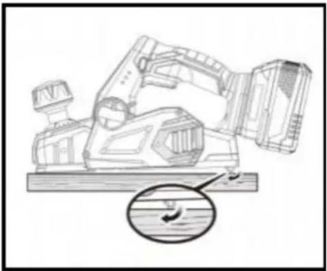
natural_image
Technical line drawing of a mechanical device with a magnified inset showing a water surface feature (no text or symbols)natural_image
Technical line drawing of a mechanical assembly with no visible text or symbolsnatural_image
Technical line drawing of hands using a lathe machine to work on a mechanical component (no text or symbols present)natural_image
Technical line drawing of a mechanical assembly (no text or symbols visible)natural_image
Technical line drawing of a mechanical device with a hand operating it (no text or symbols present)C/O YH Consulting Limited Kantoor 147, Centurion House, Londen Road, Staines-upon-Thames, Surrey, TW18 4AX
VEVOR®
TOUGH TOOLS, HALF PRICE
Technische ondersteuning en e- garantiecertificaat www.vevor.com/support
VEVOR®
TOUGH TOOLS, HALF PRICE
natural_image
Line drawing of a vintage digital camera with control panel and lens (no text or symbols)www.vevor.com/support
INNEHÅLLSFÖRTECKNING
JUSTERING AV AVGASRIKTNING

WARNING:
natural_image
Technical line drawing of a mechanical device with a magnified inset showing a close-up of the component (no text or symbols present)
natural_image
Technical line drawing of a mechanical assembly with a magnified inset showing a water feature (no text or symbols)natural_image
Technical line drawing of a mechanical assembly with no visible text or symbolsnatural_image
Technical line drawing of hands operating a mechanical setup with a vise and tool (no text or symbols)ÿ Spänn fast verket ordentligt
natural_image
Technical line drawing of a mechanical assembly (no text or symbols visible)natural_image
Technical line drawing of a mechanical device with a hand operating it (no text or symbols present)C/O YH Consulting Limited Office 147, Centurion House, London Road, Staines-upon-Thames, Surrey, TW18 4AX
VEVOR®
TOUGH TOOLS, HALF PRICE