
Thickness Planer M1B-LS-3301 - Plane Vevor - Free user manual and instructions
Find the device manual for free Thickness Planer M1B-LS-3301 Vevor in PDF.
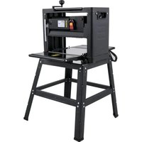


| Product type | Electric Planer (Thicknesser) |
| Brand | Vevor |
| Model | M1B-LS-3301 |
| Power supply | 230 V ~ 50 Hz, 2000 W |
| Max. planing width | 330 mm |
| Planing depth | 0 - 3 mm |
| Planing height | 6 - 160 mm |
| Feed speed | 6 m/min |
| Number of blades | 2 |
| Table dimensions | 330 x 290 mm |
| Net weight | 27.5 kg |
| Gross weight | 29.3 kg |
| Package dimensions | 570 x 360 x 505 mm |
| Main functions | Rough and fine planing of dry wooden boards |
| Safety | Double insulation (Class II), overcurrent protection, anti-kickback pawls, emergency stop |
| Maintenance and cleaning | Regular chip cleaning, chain and screw lubrication, carbon brush replacement |
| Spare parts and repairability | Knife blades, carbon brushes, protection fuse – repair by an authorized center |
| General information | Domestic and professional use – technical support: www.vevor.com/support |
Frequently Asked Questions - Thickness Planer M1B-LS-3301 Vevor
User questions about Thickness Planer M1B-LS-3301 Vevor
0 question about this device. Answer the ones you know or ask your own.
Ask a new question about this device
Download the instructions for your Plane in PDF format for free! Find your manual Thickness Planer M1B-LS-3301 - Vevor and take your electronic device back in hand. On this page are published all the documents necessary for the use of your device. Thickness Planer M1B-LS-3301 by Vevor.
USER MANUAL Thickness Planer M1B-LS-3301 Vevor
THICKNESSER USER MANUAL
MODEL: M1B-LS-3301
We continue to be committed to providing you with tools at competitive prices. "Save Half", "Half Price", or any other similar expressions used by us only represent an estimate of savings you might benefit from buying certain tools with us compared to the top brands and do not necessarily mean to cover all categories of tools offered by us. You are kindly reminded to verify carefully when placing an order with us if you are actually saving half in comparison with the top major brands.
VEVOR®
Thicknesser
NEED HELP? CONTACT US!
Have product questions? Need technical support? Please feel free to contact us:
This is the original instruction. Please read all manual instructions carefully before operating. VEVOR reserves clear interpretation of our user manual. The appearance of the product shall be subject to the product you received. Please forgive us that we won't inform you again if there is any technology or software updates on our product.
SAFETY INSTRUCTIONS
IMPORTANT: Carefully read the instructions in this manual as well as the general safety instructions before using this tool.

Before using the tool, read the instruction book carefully.
Class II appliance, reinforced insulation or double insulation
Keep the packaging material out of the reach of children -- risk of suffocation.
WARNING! Always take basic safety precautions when using power tools to safeguard against the risk of fire, electric shock and/or personal injury.
- For safe operation. We recommend that you take appropriate measures for the protection of hearing if the sound pressure of 85dB (A) is exceeded.
- Keep the work area clean. Cluttered work areas increase the risk of accidents and injuries.
- Keep the workplace environment safe. Do not use power tools in damp or wet areas. Do not expose power tools to rain. Make sure the work area is well lit. Do not use power tools in explosive environments, such as in the vicinity of flammable liquids, gases or dust.
- Protect against the risk of electric shock. Avoid body contact with earthed surfaces, such as pipes, radiators, cookers and refrigerators.
- Keep children at a safe distance. Do not allow onlookers to touch the tool or the extension cord. Onlookers should be kept away from the work area.
- Put away tools that are not being used. When not in use, store the tool in a dry place out of the reach of children.
- Do not force the tool. The tool does the job better and safer when used at the rate for which it was designed.
- Use the correct machine. Do not force small machines or accessories to perform jobs that require a powerful machine. Use tools only for their intended purpose.
- Wear suitable clothing. Do not wear loose clothing or jewellery. They can be caught in moving parts. Non-slip shoes are recommended when working outdoors. Wear a hair net if you have long hair.
- Wear safety glasses. Wear a dust mask if the work generates dust.
- Be careful with the cable. Never carry the tool by the cable. Do not pull the cable to disconnect the plug from the socket. Keep the cable away from heat, oil and sharp edges.
- Secure the workpiece. Secure the workpiece with a stand. This is safer than using your hands and means you have both hands free to operate the tool.
- Do not overreach. Always maintain a firm footing and good balance.
- Maintain the tool in good care. Keep cutting tools sharp and clean for better, safer work. Follow the instructions for lubricating and for the replacement of accessories. Check power cords regularly. If damaged, they must be replaced at an authorized service center. Check extension cords at regular intervals and replace them if they are damaged. Keep the hands clean, dry, and free from oil and grease.
- Always unplug the power cord when the tool is not being used, and before carrying out service work or changing accessories, such as knife blades, carbon brushes, gears, and so on.
- Remove adjuster keys, spanners, and other assembling tools. Remove adjuster keys, spanners, and other assembling tools before starting the power tool.
- Avoid accidental starting. Never carry a power tool with your finger on the switch when it is connected to the mains. Make sure the power switch is in the OFF position before plugging in the power cord.
- If using the tool outdoors, only use an extension cord approved for outdoor use.
- Stay alert. Always be careful when using the equipment. Use your common sense. Do not use the tool if you are tired.
- Connect dust extraction equipment. If dust extraction and dust collection equipment is provided, this should be connected and used correctly.
- Check for damaged parts. If a guard or some other part has been damaged, check carefully before using the tool to ensure that it will operate correctly and as intended. Make sure that moving parts are properly adjusted and do not jam, and that no parts are incorrectly fitted or damaged. Check for any other factors that could influence functionality. Guards or other parts that are damaged must be repaired or replaced by an authorized service center, unless otherwise specified in these instructions. If the power switch does not work, it must be replaced by an authorized service center. Do not use the tool if it cannot be switched on and off using the power switch.
WARNING! The use of accessories or attachments other than those recommended in these operating instructions can result in personal injury. Repairs must only be carried out by qualified personnel. This power tool has been manufactured in compliance with current safety standards and requirements. Repair may only be carried out by qualified personnel using identical spare parts. Failure to carry out repairs correctly can result in the risk of personal injury, death, or material damage.
NOTE: A temporary voltage drop can occur when starting the machine, which could affect other equipment. If the main supply impedance Zmax is lower than 0.206 ohms, this kind of interference is common. Contact your electricity supplier for more information.
IMPORTANT SAFETY INSTRUCTIONS
- Wear safety glasses. Don't send wood into outfeed side.
- Before use, check that all screw connections are properly tightened.
- Do not force the tool. Let the feed mechanism do the work. Never insert objects or body parts in the outfeed.
- Check regularly that the rubber roller and iron roller are clean. If the rollers are contaminated, the workpiece will not feed correctly, which poses a risk of personal injury.
- Do not machine workpieces with many knots or splits.
- The operating position is in front of the machine. Stand by the side of the infeed table.
- Remove any nails, screws, and other metal objects from the workpiece before machining.
- Check that the blades are correctly installed.
- Handle the knife blades with care—risk of personal injury and/or damage to property.
- Never start to plane until the blade shaft has reached full speed.
- Never use blunt blades—risk of kickback.
- Always replace or sharpen all blades at the same time. All blades must be of the same size and weight.
- Never insert your fingers or other body parts in the chip outlet side—risk of personal injury—DANGER.
- Please check that the recoil claw is in the correct position.
- If the wood does not feed smoothly, do not force it; check if the machine has any problems.
- Do not wear gloves to plane wood.
- Do not plane wet wood, as it will cause the feed roller to slip and lead to machine damage.
- Do not plane hard wood, as it will shorten the working life of the knife blades.
- Do not plane the wood for too long, as the machine will be overloaded, which will affect the planing surface quality.
TECHNICAL DATA
| Model : Specs: | M1B-LS-3301 For US user | M1B-LS-3301 For European users |
| Rating(s): | 110V~60Hz 2000W | 230V~50Hz 2000W |
| Feed Speed: | 6m/min | 6m/min |
| blade: | 2pcs | 2pcs |
| Max.planing width: | 330mm | 330mm |
| Planing depth: | 0-3mm | 0-3mm |
| Planing height: | 6-160mm | 6-160mm |
| G.W: 29.3kg | 29.3kg | |
| N.W: 27.5kg | 27.5kg | |
| Working table size: | 330x290mm | 330x290mm |
| Packing size: | 570×360×505mm | 570×360×505mm |
| Tested wood width is 150mm for feeding speed | ||
DESCRIPTION
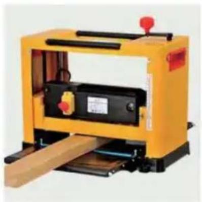
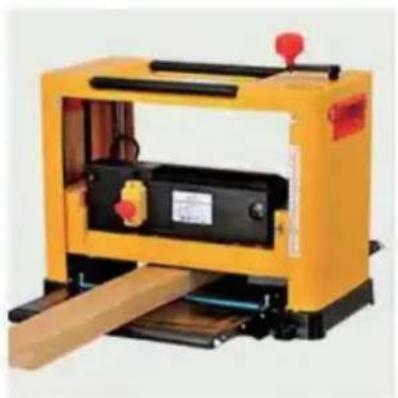
- The tool is designed for planing wooden planks and dry wood. It is forbidden to plane other materials, such as metals, plastics, branches, tree trunks, wet wood, and very hard wood.
- The tool is intended for household and professional use.
- Please use this machine correctly. If you do not know how to use it, please contact the factory.
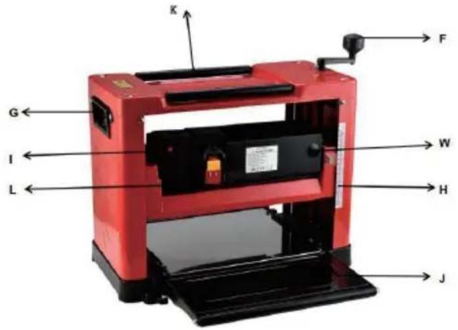
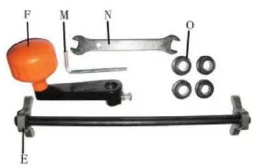
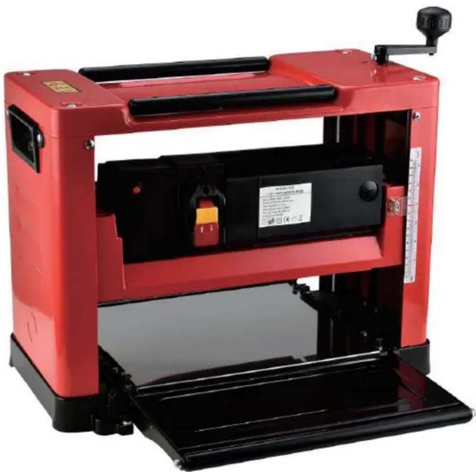
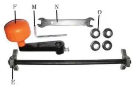
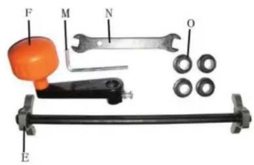
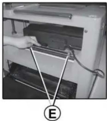
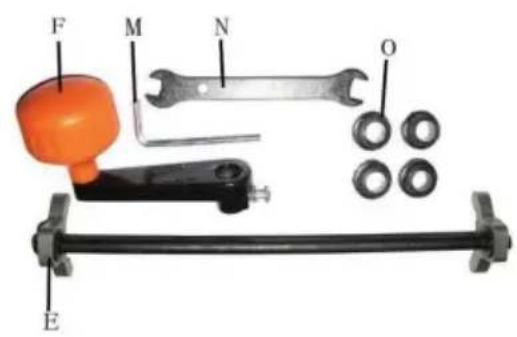
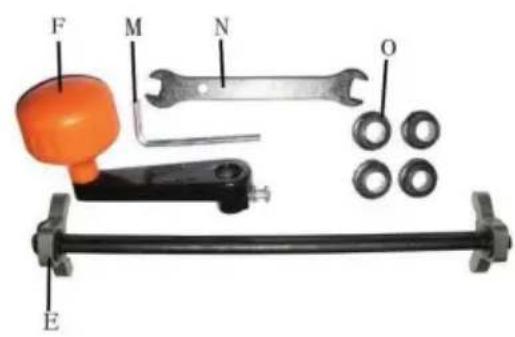
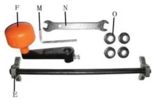
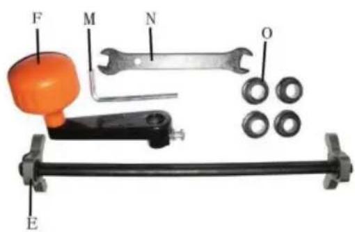
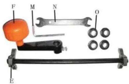
E-Knife blade bit gauge H-Depth label K-Roller bar N-Open spanner
F-Depth adjustment handle I-Overcurrent protective device L-Switch O-Rubber feet
G-Carrying handle J-Extension table M-Allen wrench W-Carbon brush cover
Advised to wear ear protection. Advised to wear safety glasses. Advised to wear dust mask.

OPERATION STEPS
Unpacking
Carefully unpack the machine. The packaging must be recycled in accordance with local regulations.
WARNING! Turn off the machine and unplug the power cord before cleaning, performing maintenance, and adjustment.
Assembly
Before using the machine, it must be fully assembled according to the requirements.
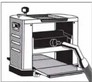
Evacuation of shavings and wood dust:
The tool is equipped with a dust hood with a vacuum cleaner connection (V). This dust hood is located at the back of the machine for connection to a vacuum cleaner. A flexible hose (not supplied) can be connected to the collector. Some species of wood or processed wood produce sawdust harmful to health.
Please note: Always use the tool connected to a vacuum cleaner.
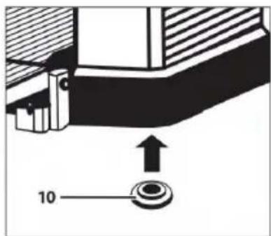
Install rubber feet (O):
If you do not need to use the foot frame for working, please insert 4 rubber feet into the four holes in the bottom of the machine.
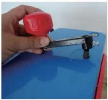
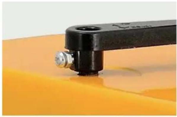
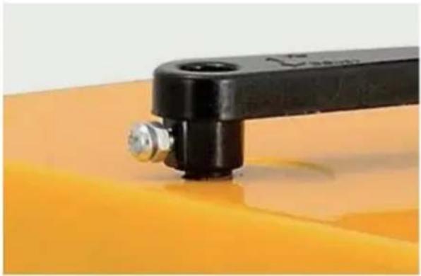
Install depth adjustment handle:
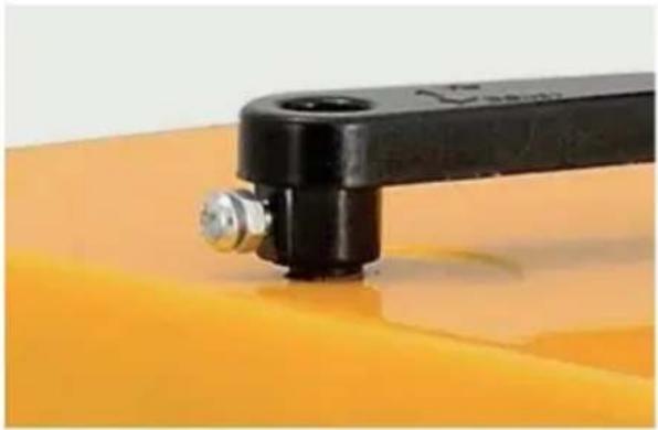
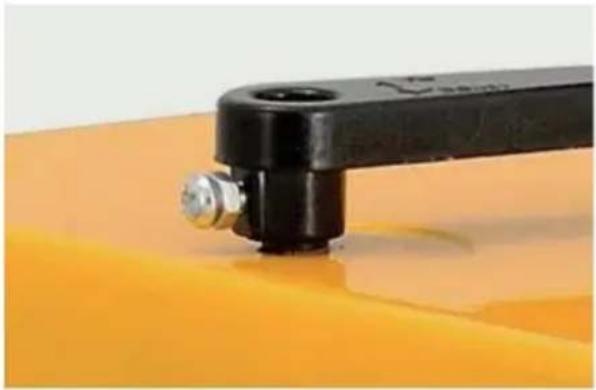
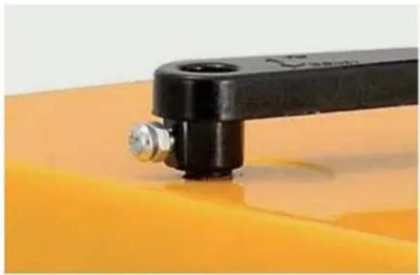
Place the depth adjustment handle (F) on the protruding shaft to the right of the machine's top surface. Push on the handle firmly and lock it with the supplied screw.
Adjust depth of the planer: In order to be able to completely correct and safely operate this machine, the user must know how to adjust it correctly. Very important!!!
Rotate the depth adjustment handle (F) one full circle; the machine depth can be raised or lowered by 1.5 mm.
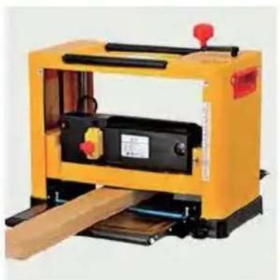
Before using, plane the wood a few times to ensure the surface of the wood is completely horizontal in later use. Please refer to the correct wood width range to adjust the depth of the one-time planer:
| width of wood (mm) cutting depth (mm) | |
| 0~100 | 0~3 |
| 160~210 | 0~2 |
| 210~330 | 0~1 |
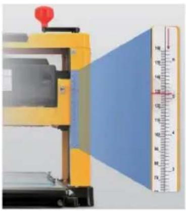
First, the user needs a ruler to measure the thickness of the wood to be planed. Then observe the depth label (H) to adjust the depth label to the thickness required by the user.
For example: if the thickness of the wood is 200 mm and the user wants to plane 2 mm, the depth label pointer should be at 198 mm. In this way, the thickness required by the user can be reached during the one-time working process.
Please note: The distance between the bottom of the machine and the knife shaft is the thickness of the wood when it is planed. The difference between the thickness of the wood when it comes out of the machine and the thickness when it comes in is the thickness of the wood that was shaved off.
- Width of wood 0-100 mm, we suggest cutting depth adjust 0-3 mm, max 3 mm per time.
- Width of wood 160-210mm, we suggest cutting depth adjust 0-2mm, Max 2mm per time.
- Width of wood 210-330mm, we suggest cutting depth adjust 0-1mm, Max 1mm per time.
Warning! The length of the wood must not be less than 153mm. The thickness of the wood must not be less than 10mm.
Operate switch (power ON/OFF)
Plug the power cord into the mains supply. If you are using an extension cord, the cross section of the conductors must be sufficient for the tool's power supply. Avoid inappropriate use of cable, as this can lead to voltage drop and cause power loss and overheating.
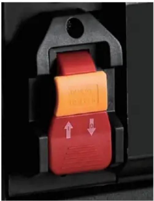
Press the button marked "I" to start the machine. Press the button marked "O" to stop the machine.
OPERATION
Coarse PLANING
Coarse planing is used to provide a reference surface for machining.
- Set a small removal setting for the best surface finish.
- Process where possible along the grain.
Note: the surface finish is affected by various factors.
- The wood's hardness, moisture content, fibre structure, etc.
- Blade sharpness, machining direction, material removal per pass, etc.
- Perform test machining to find the best setting.
PLANING
Planing involves material removal of the workpiece to the desired thickness, the machining of the surface opposite a coarse planed reference surface.
MAINTENANCE
WARNING: Turn off the machine and unplug the power cord before cleaning and maintenance. Do not use water or other liquids to clean electrical parts.
CHECK AND REPLACE THE CARBON BRUSH
- Turn off the machine, unplug the power cord and wait until all moving parts have stopped completely.
- Dismantle the carbon brush cover (W) as illustrated using a screwdriver.
- Fit the new carbon brushes. Always replace both carbon brushes at the same time.
- Replace the carbon brush cover (W).
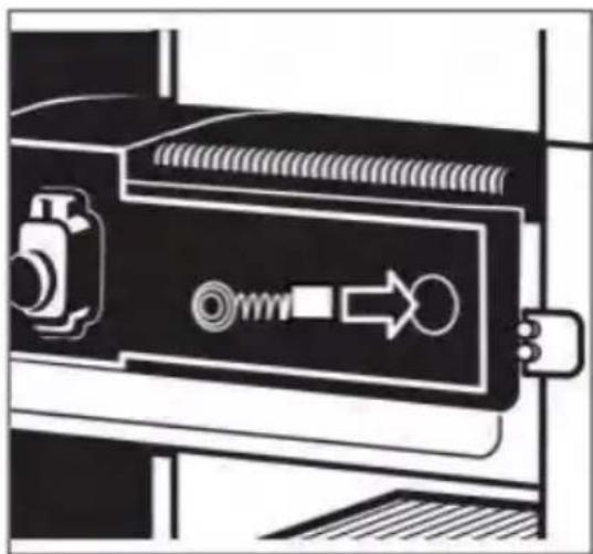
Overcurrent protective device correct use and replacement (I)
When the load power is too large, the current exceeds the load, so the overcurrent protective device will trip!
- When the overcurrent protective device trips, first disconnect the power supply of the machine, then press the protective button to reset it.
- When pressing the protective button to reset it, do not reboot immediately. Wait for the machine temperature to cool down before starting use.
- If the overcurrent protective device trips frequently, please replace it with a new one.

ADJUST TABLE EXTENSION (J)
Attention: This adjustment is already factory set. To avoid affecting the function of the machine, it needs to be checked again.
- Raise the engine body to a suitable height for easy assembly.
- Place a straightedge on the main worktable and use a ruler to measure the level of the table extension (J) and the main worktable.
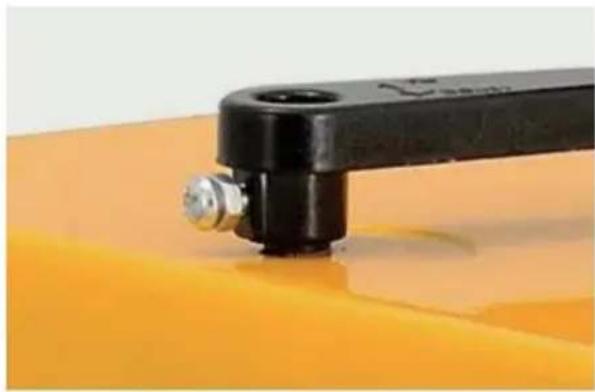
- If the table extension (J) is not flush with the main worktable, loosen the nut and turn the screw until the table extension's rollers and the main worktable touch the straightedge. Adjust both the left and right-hand table extensions (J).
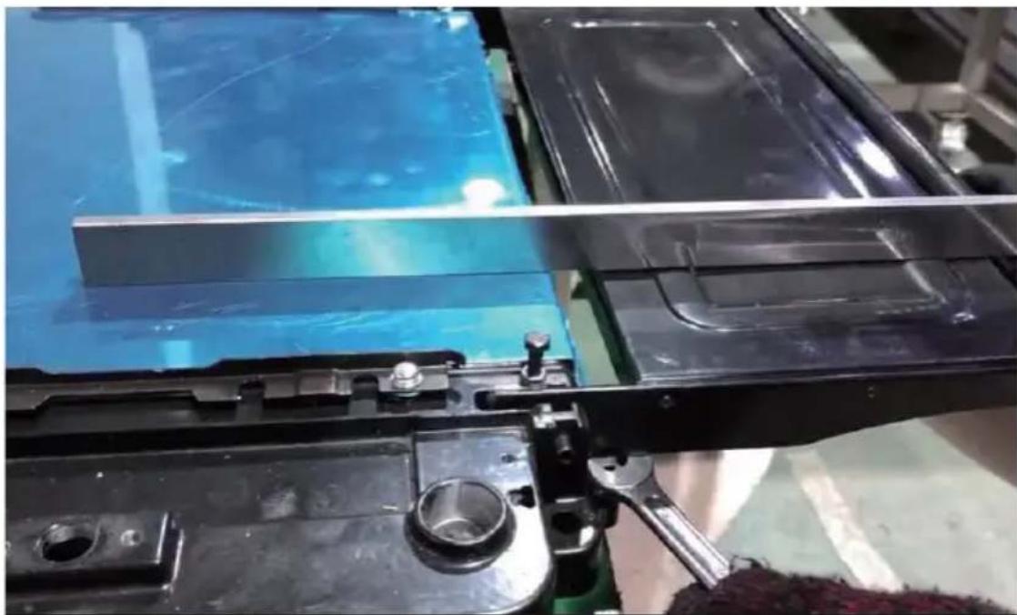
ENGINE BODY LEVEL ADJUSTMENT
ATTENTION: This adjustment is already factory set. To avoid affecting the function of the machine, it needs to be checked again. Poor parallelism is usually caused by misaligned blades or a fall in transit causing the body to tilt. Always check that the blade holder and the worktable are parallel before attempting to adjust the parallelism setting.
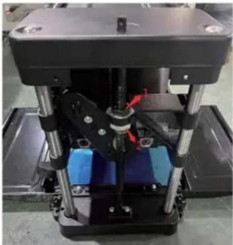
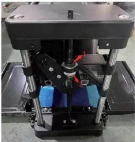
Lower the engine body to a certain height by rotating the handle. Place two wooden blocks of the same height at the lower end of the body and clamp them tightly.
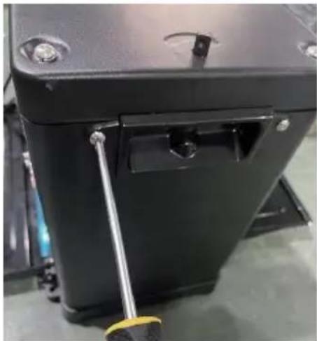
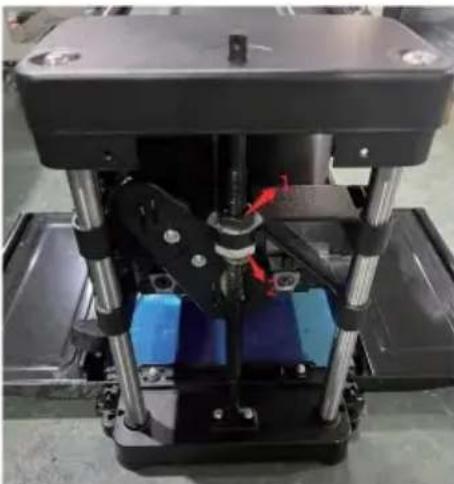
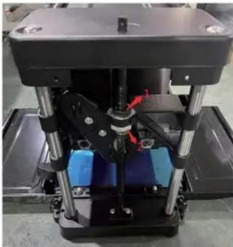
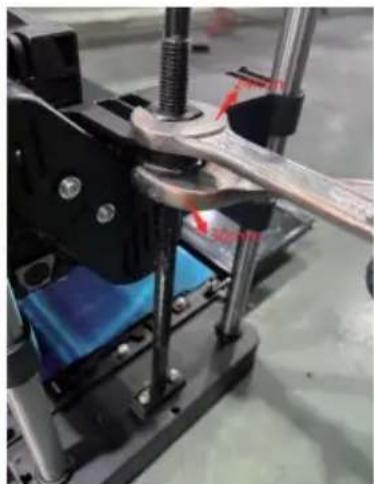
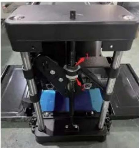
- Loosen the two screws on the handle of the right panel using a cross screwdriver. See picture 1. Attention: Only the right panel needs adjusting.
- Remove the right panel.
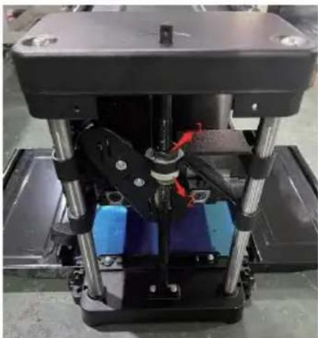
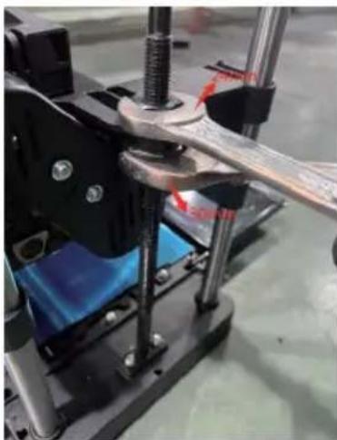
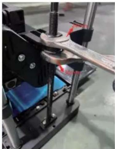
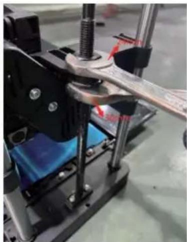
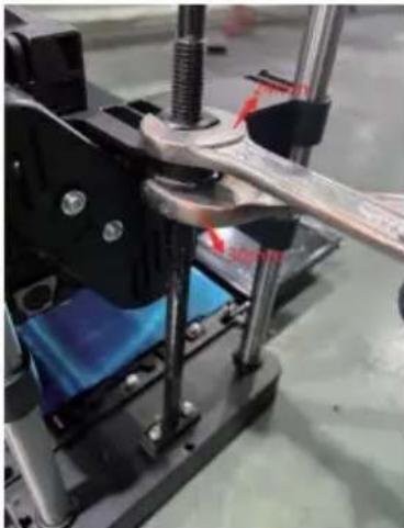
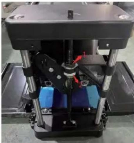
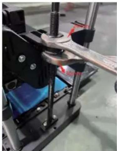
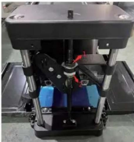
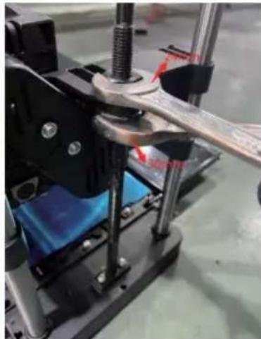
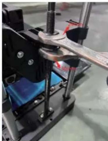
- Use a 24mm open wrench and a 30mm open wrench to adjust the engine body up and down. Position 1 uses the 24mm open wrench, position 2 uses the 30mm open wrench. Clamp the 24mm nut with the 24mm open wrench and do not rotate it. Turn the 30mm open wrench one turn to the left (clockwise) to keep the screw nut loose.
- Use the 24mm open wrench to adjust the 24mm nut. Rotate clockwise to raise the engine body and counterclockwise to lower it, until the engine body is level with the base.
- Use the 24mm open wrench to clamp the 24mm nut without rotating it, and use the 30mm open wrench to tighten the 30mm nut.
REPLACING AND ADJUSTING THE BLADES
WARNING! Turn off the machine, unplug the power cord, and wait until all moving parts have stopped completely before replacing or adjusting the blades.
Dismantling the knife blade
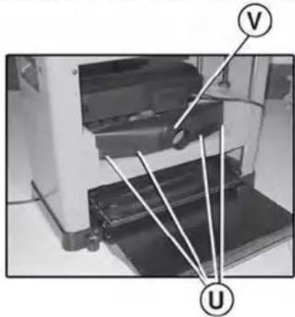
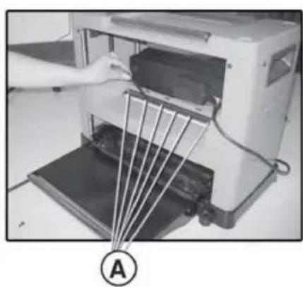
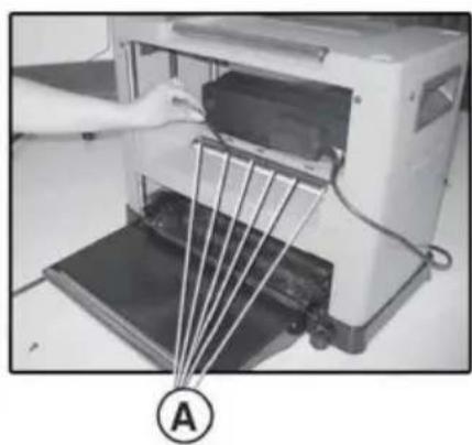
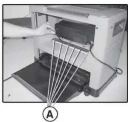
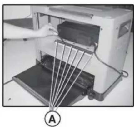
- Use the Allen wrench (N) to remove the dust hood (V) by loosening the screws (U), as shown in the picture below.
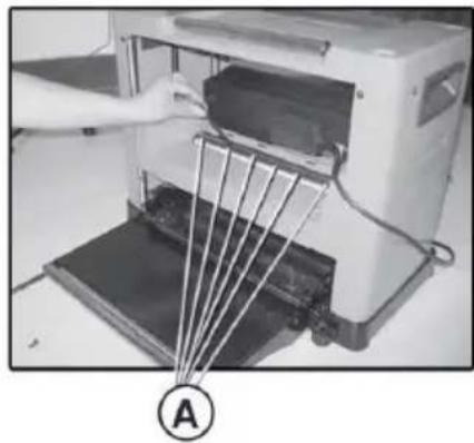
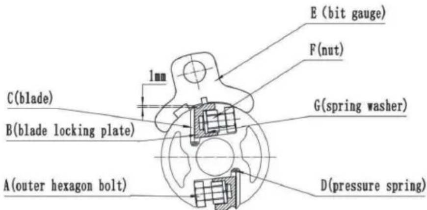
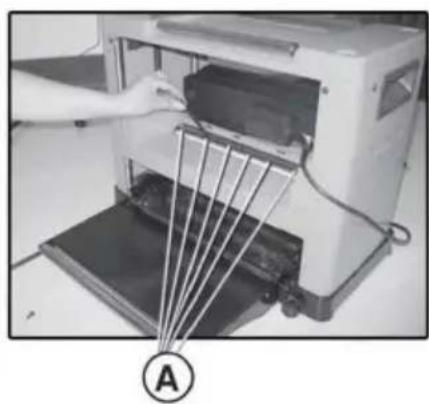
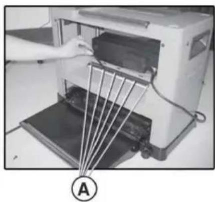
- Use the double open wrench (N) to loosen the blade locking plate (B) and knife blade (C) by turning the outer hexagon bolt (A) clockwise. The knife blades are spring-loaded (D) and can be removed once the blade locking plate is removed.
- Remove the knife blade and blade locking plate.
Install the knife blade.
- First, ensure that the pressure springs (D) on the knife shaft are in the 2 fixed holes. Align the hole in the knife blade with the pin in the blade locking plate.
- Insert the 8 outer hexagon bolts (A) into the fixed holes of the blade locking plate.
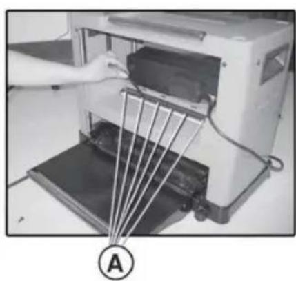
- Insert the knife blade (C), knife locking plate (B), and 8 outer hexagon bolts (A) together into the slot and lock them in position by turning the outer hexagon bolts (A) anticlockwise, but do not fully tighten. Ensure that the blades face the right direction (see picture).
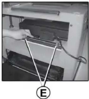
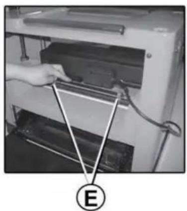
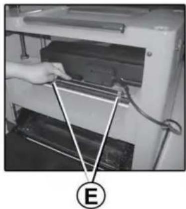
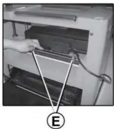
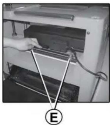
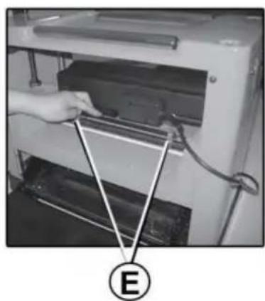
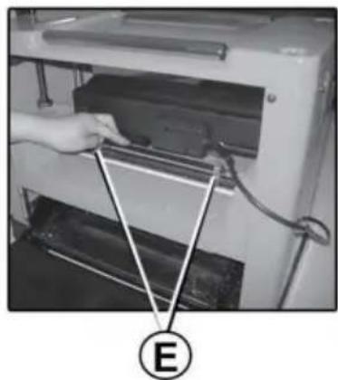
- Set the height of the knife shaft of the knife blades to 1 mm using the bit gauge (E), with the two support blocks on the left and right sides of the bit gauge pressed against the knife blade. (Loosen, if necessary, the clamping screws to move the blade to the correct position.) When the knife blade is positioned correctly, hold it firmly in place and tighten all outer hexagon bolts (A).
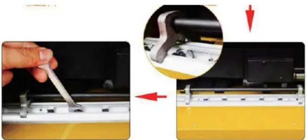
Warning! Check that all 18 screws are tightened. Turn the blade holder by hand to check that it rotates easily and smoothly. Handle the blades with caution to avoid personal injury and/or damage to property.
LUBRICATION:
- Regularly remove shavings from the depth setting chains, reduction drive, and lifting screws for the blade holder.
- Remove chips with a cloth and brush, and lightly grease with a clean brush dipped in oil.
- Never pour oil directly on the components—too much oil means dust will stick and impair lubrication, which in turn shortens component life.
- The blade holder's bearings are sealed and must not be lubricated.
MAINTENANCE
- Keep the machine clean and free of dust and chips.
- Clean reapped materials from the blade holder and tongues and carefully lubricate with a clean brush dipped in oil.
- Remove resin and the like from the rollers and work table with a non-flammable solvent.
- Clean plastic parts with a damp cloth and mild detergent. Never immerse the tool in water or any other liquid. Never use detergents or alcohol.
- Always check that all guards and other components are correctly fitted before use. Guards or other parts that are damaged must be repaired or replaced by an authorised service centre, unless otherwise specified in these instructions.
This product is subject to the provision of European Directive 2012/19/EC. The symbol showing a wheelie bin crossed through indicates that the product requires separate refuse collection in the European Union. This applies to the product and all accessories marked with this symbol. Products marked as such may not be discarded with normal domestic waste, but must be taken to a collection point for recycling electrical and electronic devices.
VEVOR®
TOUGH TOOLS, HALF PRICE
Technical Support and E-Warranty Certificate www.vevor.com/support
VEVOR®
TOUGH TOOLS, HALF PRICE
NEED HELP? CONTACT US!
OPERATION STEPS
Unpacking
ADJUSTING THE TABLE EXTENSION (J)
ADJUSTING THE LEVEL OF THE BODY OF THE
OPERATING STEPS
Unpacking
electronics www.vevor.com/support
USER MANUAL THICKNESS
MODEL: M1B-LS-3301
!NEED HELP? CONTACT
OPERATING STEPS
Unpacking
ADJUSTING THE TABLE EXTENSION (J)
ADJUSTING THE LEVEL OF THE BODY OF THE
Install rubber feet (O):
| Ancho de la madera (mm) | Profundidad de corte (mm) |
| 0~100 | 0~3 |
| 160~210 | 0~2 |
| 210~330 0~1 |
ADJUSTING THE LEVEL OF THE BODY OF THE
NEED HELP? CONTACT US
OPERATING STEPS
CAUTION ON LEVEL ADJUSTMENTS
NEED HELP? CONTACT US
OPERATING STEPS
Unpacking
Rubber feet

ADJUSTING TABLE EXTENSION (J)
ADJUSTING MOTOR BODY LEVEL
www.vevor.com/support
THICKNESSER USER MANUAL
MODEL: M1B-LS-3301
NEED HELP? CONTACT US
OPERATING STEPS
Unpacking

Adjust the planer depth
| träets bredd (mm) | skärdjup (mm) |
| 0~100 0~3 | |
| 0~2160~210 | |
| 210~330 0~1 |
ADJUST TABLE FOLLOW (J)
ADJUSTING THE MOTOR BODY LEVEL
Mount the knife blade 1.

- THICKNESSER USER MANUAL
- VEVOR®
- THICKNESSER
- NEED HELP? CONTACT US
- SAFETY INSTRUCTIONS
- IMPORTANT SAFETY INSTRUCTIONS
- TECHNICAL DATA
- DESCRIPTION
- OPERATION STEPS
- UNPACKING
- ASSEMBLY
- EVACUATION OF SHAVINGS AND WOOD DUST
- INSTALL RUBBER FEET (O)
- INSTALL DEPTH ADJUSTMENT HANDLE
- OPERATE SWITCH (POWER ON/OFF)
- OPERATION
- COARSE PLANING
- PLANING
- MAINTENANCE
- CHECK AND REPLACE THE CARBON BRUSH
- OVERCURRENT PROTECTIVE DEVICE CORRECT USE AND REPLACEMENT (I)
- ADJUST TABLE EXTENSION (J)
- ENGINE BODY LEVEL ADJUSTMENT
- REPLACING AND ADJUSTING THE BLADES
- DISMANTLING THE KNIFE BLADE
- INSTALL THE KNIFE BLADE
- LUBRICATION
- TOUGH TOOLS, HALF PRICE
- ADJUSTING THE LEVEL OF THE BODY OF THE
- OPERATING STEPS
- USER MANUAL THICKNESS
- ADJUSTING THE TABLE EXTENSION (J)
- CAUTION ON LEVEL ADJUSTMENTS
- RUBBER FEET
- ADJUSTING TABLE EXTENSION (J)
- ADJUSTING MOTOR BODY LEVEL
- ADJUST THE PLANER DEPTH
- ADJUST TABLE FOLLOW (J)
- ADJUSTING THE MOTOR BODY LEVEL
- MOUNT THE KNIFE BLADE
Brand : Vevor
Model : Thickness Planer M1B-LS-3301
Category : Plane