M1H-ZP12-254A-1 - Saw Vevor - Free user manual and instructions
Find the device manual for free M1H-ZP12-254A-1 Vevor in PDF.

| Brand | Vevor |
| Model | M1H-ZP12-254A-1 |
| Product Type | Table Saw |
| Power Supply Voltage | 220-240 V ~ 50 Hz |
| Rated Power | 1800 W |
| Blade Diameter | 254 mm (10 inches) |
| Blade Bore | 30 mm |
| No-Load Speed | 4400 RPM |
| Number of Blade Teeth | 40 |
| Max Cutting Height at 90° | 85 mm |
| Max Cutting Height at 45° | 60 mm |
| Blade Tilt Range | 0 to 45° |
| Dust Port Diameter | 35 mm |
| Net Weight | 19.3 kg |
| Main Functions | Ripping, crosscutting, miter cutting, bevel cutting, rabbeting, grooving |
| Safety Devices | Blade guard, riving knife, anti-kickback devices, safety switch with lock, reset button |
| Included Accessories | Parallel guide, miter gauge, push stick, hex key, table insert, dust adapter |
| Maintenance and Cleaning | Clean sawdust regularly, lubricate rods and gears with SAE No. 20/30 oil or WD-40, replace brushes by a professional |
| Repairability | Spare parts available from VEVOR after-sales service; entrust repairs to a qualified technician |
Frequently Asked Questions - M1H-ZP12-254A-1 Vevor
User questions about M1H-ZP12-254A-1 Vevor
0 question about this device. Answer the ones you know or ask your own.
Ask a new question about this device
Download the instructions for your Saw in PDF format for free! Find your manual M1H-ZP12-254A-1 - Vevor and take your electronic device back in hand. On this page are published all the documents necessary for the use of your device. M1H-ZP12-254A-1 by Vevor.
USER MANUAL M1H-ZP12-254A-1 Vevor
Technical Support and E-Warranty Certificate www.vevor.com/support
TABLE SAW USER MANUAL
MODEL:M1H-ZP12-254A-1
We continue to be committed to provide you tools with competitive "Save Half", "Half Price" or any other similar expressions used by us only represent estimate of savings you might benefit from buying certain tools with us compared to major top brands and does not necessarily mean to cover all categories of tools offered. You are kindly reminded to verify carefully when you are placing an order with us, where you are actually saving half in comparison with the top major brands.
MODEL:M1H-ZP12-254A-1
natural_image
Technical line drawing of a mechanical machine with no visible text or symbolsNEED HELP? CONTACT US!
Have product questions? Need technical support? Please feel free contact us:
Technical Support and E-Warranty Certificate www.vevor.com/support
This is the original instruction, please read all manual instructions carefully before operating. VEVOR reserves a clear interpretation of user manual. The appearance of the product shall be subject to product you received. Please forgive us that we won't inform you there are any technology or software updates on our product.
Table of Contents
WARNING
General Safety Rules----3
Safety Instructions for Table Saws----
Additional Safety Rules----7
Symbols----9
Glossary of Terms----12
Getting To Know Your Table Saw----
Unpacking And Checking Contents----1
Assembly----15
Storage, Transporting, and Mounting----19
Adjustments----20
Basic Table Saw Operation----2
Maintaining Your Table Saw----3
Troubleshooting----40
TECHNICAL DATA----41
Some dust created by power sanding, sawing, grinding, drilling, and other construction activities contains chemicals known to cause cancer, birth defects or other reproductive harm.
Some examples of these chemicals are:
Lead from lead-based paints,
Crystalline silica from bricks and cement
other masonry products, and
Arsenic and chromium from chemically treated lumber.
Your risk from these exposures varies, depending on how often you do this type of work. To reduce your exposure to these
gchemicals: work in a well ventilated area, a work with approved safety equipment, such as those dust masks that are specially designed to filter out microscopic particles.
Avoid prolonged contact with dust from power sanding, sawing, grinding, drilling, and other construction activities. Wear protective clothing and wash exposed areas with so and water. Allowing dust to get into your mouth or eyes or to lie on the skin may promote absorption of harmful chemicals.
General Safety Rules
WARNING
Read all safety warnings, instructions, illustrations and specifications with this power tool. Failure to follow all instructions listed below ma
electric shock, fire and/or serious injury.
SAVE ALL WARNINGS AND INSTRUCTIONS FOR FUTURE REFERENCE.
The term “power tool” in the warnings refers to your mains-operated (corded) power operated (cordless) power tool.
WORK AREA SAFETY
Keep work area clean and well lit. dark reas invite accidents.
under the influence of drugs, alcohol or
Cluttered. A moment of inattention while operat power tools may result in serious personal
Do not operate power tools in explosive atmosphere, such as in the presence of non-smable protection. Protective equipment suitable liquids, gases or dust. Power tools are created by dust mask, non-skid safety shoes, hard hearing protection used for appropriate condi-
Keep children and bystanders away who operating a power tool. Distractions can you to lose control.
Preveat unintentional starting. Ensure the switch is in the off-position before connected to power source and / or battery pack, pin up or carrying the tool. Carrying power to
ELECTRICAL SAFETY
Power tool plugs must match the out! Never modify the plug in anyway. Do any adapter plugs with earthed (ground
atour finger on the switch or energizing pow that have the switch on invites accidents .
power tools. Unmodifiedlugs and matching outlets will reduce risk of electric shock
Remove any adjusting key or wrench before turning the power tool on. A wrench or left attached to a rotating part of the power
Avoid body contact with earthed or gr surfaces, such as pipes, radiators, rang
roundedesult in personal injury .
and refrigerators. There is an increased electric shock if your body is earthed o
Do not overreach. Keep proper footing an risk of balance at all times. This enables better ground of the power tool in unexpecteds situati
Do not expose power tools to rain o ditions. Water entering a power tool will the risk of electric shock.
- wet con- Dress properly. Do not wear loose clothin increase jewelry. Keep your hair, clothing and glov away from moving parts. Loose clothes, jew erly cord for long hair can be caught in moving
Do not abuse the cord. Never use the carrying, pulling or unplugging the power. Keep cord aw from heat, oil, sharp ed moving parts. Damaged or entangled con crease the risk of electric shock.
If devices are provided for the connection des of dust extraction and collection facilities, ensure these are connected and properly use Use of dust collection can reduce dust-relate hazards.
When operating a power tool outdoors, an extension cord suitable for outdoor Use of a cord suitable for outdoor use the risk of electric shock.
Do not let familiarity gained from frequent reduces of tools allow you to become complacent ignore tool safety principles. A careless ac location is cause severe injury within a fraction of
If operating a power tool in a damp unavoidable, use a Ground Fault Circuit rupter (GFCI) protected supply. Use of GFCI reduces the risk of electric shock
an POWER TOOL USE AND CARE Do not force the power tool. Use the power tool for your application. The correct power tool will do the job better and safer rate for which it was designed.
PERSONAL SAFETY
Stay alert, wh what you are doing an common sense when operating a power. Do not use a power tool while you
SAVE THESE INSTRUCTIONS
General Safety Rules
Do not use the power tool if the switch does
not turn it on and off. Any power tool that can not be controlled with the switch is dangerous. Keep cutting tools sharp and clean. Proper and must be repaired. Maintained cutting tools with sharp cutting ends are less likely to bind and are easier to
Disconnect the plug from the power source and/or remove the battery pack, if detachable etc. In accordance with these instructions, taking from the power tool before making any adjustments, changing accessories, or storing work to be performed. Use of the power tools. Such preventive safety measures reduce the risk of starting the power tool accidentally.
Store idle power tools out of the hireach of clean and free from oil and grease. Slipp dren and do not allow persons unfamiliar with the power tool or these instructions to operate the power tool. Power tools are dangerous in the hands of untrained users. Keep handles and grasping surfaces dry, handles and grasping surfaces do not allow safe handling and control of the tool in unexpected situations.
Maintain powertools and accessories. Checkfor SERVICE misalignment or binding of moving parts, have your power tool serviced by a qua breakage of parts and any other condition repair person using only identical replacement parts. This will ensure that the safety damaged, have the power tool repaired before power tool is maintained. use. Many accidents are caused by poor
Safety Instructions for Table Saws
GUARDING RELATED WARNINGS Keep guards in place. Guards must be working order and be properly mounted. A guard that is loose, damaged, or is not correctly must be repaired or replaced.
Make sure the saw blade is not contacting guard, riving knife or the workpiece before switch is turned on. Inadvertent contact of it meeting with the saw blade could cause a h condition.
Always use saw blade guard, riving for every through-cutting operation. For through-cutting operations where the saw cuts completely through the thickness of the workpiece, the guard and other safety help reduce the risk of injury.
Adjust the riving knife as described in the knee and struction manual. Incorrect spacing, positioning and alignment can make the riving knife in tive in reducing the likelihood of kickback . devices For the riving knife and to work, they n engaged in the workpiece.
Immediately reattach the guarding system after completing an operation (such as betting, dadoing or resawing cuts) which requires removal of the guard, riving knife and/or. The guard, riving knife, and help to reduce the risk of injury.
The riving knife and are ineffective when cut workpieces that are too short to be engaged by the riving knife and anti-kick-back device. Under these conditions a kickback cannot be prevented by the riving knife and anti-kick-device.
Safety Instructions for Table Saws
Use the appropriate saw blade for the Neving reach around or over a rotating saw knife. For the riving knife to function problade, Reaching for a workpiece may lead saw blade diameter must match the appropriate contact with the moving saw blade riving knife and the body of the saw blade must be thinner than the thickness of the riving knife and the cutting width of the saw blade must be wider than the thickness of the riving knife. and/or wide workpiece has a tendency to p
CUTTING PROCEDURES WARNINGS

Never place your fingers n the vicinity or in line
with the saw blade. A moment of inattel slip could direct your hand towards the s and result in serious personal injury .
Feed the workpiece at an even pace. Do bend or twist the workpiece. If jamming cues, turn the tool off immediately, unplug saw blade tool and clear the jam. Jamming the saw by the workpiece can cause kickback or sta
Feed the workpiece into the saw blade motor cutter only against the direction of rotation. Feed-
ing the workpiece in the same direction saw blade is rotating above the table made the workpiece, and your hand, being pulled by the saw blade.
Do not remove pieces of cut-off material while the saw is running. The material made came trapped between the fence or inside saw blade guard and the saw blade pulling fingers into the saw blade. Turn the saw
Never use the mitre gauge feed the work piece when ripping and do not use th
wait until the saw blade stops before remov he rip material .
fence as a length stop when cross cutting with
the miter gauge. Guiding the workpiece rip fence and the miter gauge at the sa increases the likelihood of saw blade bind kickback .
Was the auxiliary fence in contact with th top whenipping workpieces less than 2 m thick. A thin workpiece may wedge under t fing and create a kickback .
When ripping, always apply the workpiece
KICKBACK CAUSES AND RELATED WARNINGS
feeding force between the fence and the saw
blade. Use a push stick when the distance be is a sudden reaction of the workp tween the fence and the saw blade is to less pitned, jammed saw blade or misalig 150 mm, and use a push block when of this dis- the workpiece with respect to the tance is ends than 50 mm. "Work helping blade- or when a part of the workpiece bin vices will keep your hand at a safe distance then saw blade and the rip fence or the saw blade . fixed object.
Use only the push stick provided by ufacturer or constructed in accordance with the instructions. This push stick provides the current distance of the hand from the sa
thest frequently during kickback, the workpiece wived from the table byr thportion of the saw bladfi- and is propelled towards the operator blade. Kickback is the result of saw misuse and/or
Never use a damaged or cut push s damaged push stick may break causing hand to slip into the saw blade.
rict Operating procedures or conditions and your avoided by taking proper precautions as below .
Do not perform any operation "freehand Never- stand directly in line with the saw ways use either the rip fence or the Ashays position your body on the same gauge to position and guide the workpiece the saw blade as the fence. Kickback
"Freehand" means using your hands to support the workpiece at high velocity towards or guide the workpiece, in lieu of a ripening standing in front and in line with the miter gauge. Freehand sawing leads to blade alignment, binding and kickback.
SAVE THESE INSTRUCTIONS
Safety Instructions for Table Saws
Never reach over or in back of the to pull or to support the workpiece. contact with the saw blade may occur o- may drag your fingers into the saw blad
Never hold and press the workpiece the being cut off against the rotating saw Pressing the workpiece being cut off again saw blade will create a binding condition back .
saw blade PABLE SAW OPERATING Accidental PROCEDURE WARNINGS Turn off the table saw and disconnect the power cord when removing the table insert, that changing the saw blade or making adjust- ment to the riving knife, antikickback device or saw blade guard, and when the machine is aist the left unattended. Precautionary measures will and Rick avoid accidents .
Align the fence to be parallel with the blade. A misaligned fence will pinch the piece against saw blade and create kick
Use a feather board to guide the workpiece against the table and fence making non- through cuts such as rabbeting, dadoing or resawing cuts. A featherboard helps to control the workpiece in the event of a kickback.
Use extra caution when making a cut into blind areas of assembled workpieces. truding saw blade may cut objects that kickback.
Support large panels to minimize the r saw blade pinching and kickback.aneLarge tend to sag under their own weight. Support(s) must be placed under all portions of the overhanging the table top.
Use extra caution when cutting a wor that is twisted, knotted, warped or does not have a straight edge to guide it with gauge or along the fence. A warped, knotted, or twisted workpiece is unstable and causes alignment of the kerf with the saw blade, binding and kickback.
Never cut more than one workpiece, stacked vertically or horizontally. The saw blade pick up one or more pieces and cause kickback.
When restarting the saw with the saw the workpiece, center the saw blade in the kerf so that the saw teeth are not engaged material. If the saw blade binds, it may lift up the workpiece and cause kickback when the restarted .
Keep saw blades clean, sharp, and w cient set. Never use warped saw blades or saw blades with cracked or broken teeth. Sharp and properly set saw blades rein binding, stalling and kickback.
The Never Weave the table saw running unattended. Turn it off and don't leave the tool until it comes to a complete stop. Tended at running saw is an uncontrolled hazard.
Locate the table saw in a well-lit and level area where you can maintain good footing and balance. It should be installed in an area that provides enough room to easily handle the size of your workpiece. Cramped, dark areas, and uneven slippery floors invite accidents.
The frequently clean and remove sawdust from under the saw table and/or the dust collection device. Accumulated sawdust is combustible and may self-ignite. risk of
The table saw must be secured. A table is that is not properly secured may move or tip over.
Remove tools, wood scraps, etc. from the table before the table saw is turned on. Distraction or a potential jam can be dangerous.
Always use saw blades with correct size shape (diamond versus round) of arbor holes.
Saw blades that do not match the mounting hardware of the saw will run off-center, causing loss of control.
Never use damaged or incorrect saw blade mounting means such anger, saw blade washers, bolts or nuts. These mounting means were specially designed for your saw for saation and optimum performance.
Neyer stand on the table saw; do not use it as a stepping stool. Serious injury could occur if the tool is tipped or if the cutting tool is accidentally contacted.
Make sure that the saw blade is installed to rotate in the proper direction. Do not use grinding wheels, wire brushes, or abrasive wheels on a table saw. Improper saw blade installation or use of accessories not recommended may cause serious injury.
SAVE THESE INSTRUCTIONS
Additional Safety Rules
MAKE WORKSHOP CHILD-PROOF with p proper alignment with the sawblade. If rip locks, master switches. at the time, check to see if the rip fence
Use only recommended accessories. Use only accessories recommended by the manufacture THINK of SAFETY: Safety is a combination of your model. Other accessories maybe hazardous common sense and alertness at all time. Do not use any blade or other cutting tool when the table saw is being used .
Do not use any blade or other cutting tool marked for an operating speed less than 5000
R.P.M. Risk of serious injury .
WARNING
The operation of any power tool can result in foreign o
Ensure that blade or other cutting tool washers and arbor nut are installed properly. Reference instructions for removal and installation of the blade. damage . Always we
the eyes, which can
Never operate the saw unless the improper safety goggles that insert is installed. Make sure the table insert with ANSI Z87 flush or slightly below the table surface (shown frontpackage) and flush to slightly above at the rear of insert commencing power

Always inspect table saw prior to every use. If any part of your saw is missing, malfunction before each use, re-
has been damaged or broken (such as the viewmodr warnings located on the table switch or other operating control, a safety device, or the power cord), cease operat immediately TABLE SAW STAND SAFETY until the particular part is prop repaired or INSTRUCTIONS
WARNING
Read a instructions. Fail to follow all instructions lis
Plastic and composite (lhardboard) materials may be cut on your saw. However, since these are usually quite hard and periy, the may not stop a kickback. Therefore, be especially attentive to following proper set-up and cutting procedures for ripping. Do not stand, or permit anyone else to stand, in line below may result in serious personal injury. Fully-assemble and tighten all the fastener required for this stand. Also remember to casonally check the stand and make sure still tight. A loose stand is unstable and in use and cause serious injury.
with a potential kickback. Turn the tool switch off and disconnect power before mounting the saw to the s Uninfended startup during assembly can cause molding. Replace the guard as soon as in way op-
eration is completed.
Use auxiliary facing on miter gauge to crease stability and control. Crosscutting ations are more conveniently worked and greater safety if an auxiliary wood facing attached to the miter gauge. See “Ripiliary Facing.”
Before operating, make sure that the entire unit is placed on a solid, level surface.
Serious injury could occur if the tool is un with it tips.
Avoid awkward operations and hand positions. Dently contacted . Do not store materialsWhere a sudden slip could cause fingers near the tool such that it is necessary tomove into the sawblade or other cutting tool or its stand to reach them .
If you stall or jam the sawblade in the workpiece, turn saw "OFF" and unplug the tool, remove the workpiece from the sawblade, and check to see if the sawblade is parallel to the table slots or grooves and if the spreaders is in SAVE THESE INSTRUCTIONS
Motor Specifications & Electrical Requirements
Motor Specifications
to the ground prong in the attachment plug the other end .
In the event of a malfunction or breakdown, the other end grounding provides a path of least resistance for electric current to reduce the risk of electric shock. This tool is equipped with an electric cord having an equipment-grounding conductor and a grounding plug. The plug must be plugged into a matching outlet that is properly installed and grounded in accordance with all local codes and ordinances. This saw is wired for operation on 120 volts, 60 Hz. alternating current. Before connecting the motor cord to a power source, make certain that the switch is in the "OFF" position and be sure that the electric current is of the same characteristics as that stamped on the table saw nameplate.
Connection To A Power Source
This machine must be grounded while in use to protect the operator from electric shock.
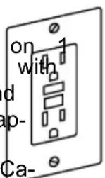
Plug the power cord into a 120V properly grounded type outlet protected by a 15-amp dual-element time-delay fuse or circuit breaker
Not all outlets are properly grounded. If you are not sure that your outlet, as pictured on this page, is properly grounded; have it checked by a qualified electrician.
WARNING
To avoid electric shock do not touch the metal progs
on the plug when installing or removing the plug to or from the outlet.
WARNING
Failure to properly ground this power tool can cause
electrocution or serious shock, particularly when used near metal plumbing or other metal objects. If shocked, your reaction could cause your hands to hit the tool.
WARNING
If power cord is worn, cut or damaged in any way, have it
replaced immediately to avoid shock or fire hazard.
Your unit is for use on volts and is equipped with a 3-conductor cord and grounding type plug, approved by Underwriters Laboratories and the Ca-
nadian Standards Association. The ground conductor has a green jacket and is attached to the tool housing at one end and
If the outlet you are planning to use for this power tool is of the two-prong type, DO NOT REMOVE OR ALTER THE GROUNDING PRONG IN ANY MANNER. Have a qualified electrician replace the TWO-prong outlet with a properly grounded THREE-prong outlet. Do not use any adapter plugs.
Improper connection of the equipment-grounding conductor can result in a risk of electric shock. The conductor with insulation having an outer surface that is green with or without yellow stripes is the equipment grounding conductor. If repair or replacement of the electric cord or plug is necessary, do not connect the equipment grounding conductor to a live terminal.
Check with a qualified electrician or service personnel if the grounding instructions are not completely understood, or if in doubt whether the tool is properly grounded.
Extension Cords

Replace damaged cords immediately. Use of damaged
cords can shock, burn or electrocute .

use proper eidans cords. Use only 3-wire exten-
sion cords which have 3-prong grounding type plugs and 3-pole receptacles which accept the tool's plug. If an extension cord is necessary, a cord with adequate size conductors should be used to prevent excessive voltage drop, loss of power or overheating. The table shows the correct size to use, depending on cord length and name-plate amperage rating of the tool. If in doubt, use the next heavier gauge. Always use U.L. and CSA listed extension cords.
RECOMMENDED SIZES OF EXTENSION CORDS 120 VOLT ALTERNATING CURRENT TOOLS
| Tool's Ampere Rating | Cord Size in A.W. | G. Wire Sizes2in mm | ||||||
| Cord Length in Feet | Cord Length in Meters | |||||||
| 25 | 50 | 100 | 150 | 15 | 30 | 60 | 120 | |
| 3-6 | 18 | 16 | 16 | 14 | 0.75 | 0.75 | 1.5 | 2.5 |
| 6-8 | 18 | 16 | 14 | 12 | 0.75 | 1.0 | 2.5 | 4.0 |
| 8-10 | 18 | 16 | 14 | 12 | 0.75 | 1.0 | 2.5 | 4.0 |
| 10-12 | 16 | 16 | 14 | 12 | 1.0 | 2.5 | 4.0 | - |
| 12-16 | 14 | 12 | - | - | - | - | - | - |
NOTE: The smaller the gauge number, the heavier the cord.
Symbols
Safety Symbols
The purpose of safety symbols is to attract your attention to possible dangers . The and the explanations with them deserve your careful attention and understanding . Th warnings do not, by themselves, eliminate any danger . The instructions and warnings no substitutes for proper accident prevention measures .
WARNING Be sure to read and understand all safety instructions in this Own Manual, including all safety alert symbols such as “DANGER,” “WARNING,” and “CAUTION” before using this tool. Failure to following all instru listed below may result in electric shock, fire, and/or serious personal injury.
| The definitions below describe the level of severity for each signal word. Please read pay attention to these symbols . | |
 | This is the safety alert symbol . It is used to alert you to injury hazards. Obey all safety messages that follow this symbol to possible injury or death . |
 | DANGER indicates a hazardous situation which, if not avoided, in death or serious injury . |
 | WARNING indicates a hazardous situation which, if not avoided, result in death or serious injury . |
 | CAUTION, used with the safety alert symbol, indicates a hazardous situation which, if not avoided, will result in minor or moderate injury . |
Damage Prevention and Information Messages
These inform the user of important information and/or instructions that could lead to other property damage if they are not followed. Each message is preceded by the as in the example below:
NOTICE: Equipment and/or property damage may result if these instructions are not followed.

natural_image
Icon of a person wearing glasses inside a circle (no text or symbols)WARNING The operation of any power tools can result in foreign objects being thrown into your eyes, which can result in severe ey damage. Before beginning power tool operation, always wear safety goggles or safety glasses with side s and a full face shield when needed . We recommend a Wide Vis Mask for use over eyeglasses or standard safety glasses with side shields . Always use eye protection which is marked to comply wit Z87.1.
Symbols
IMPORTANT: Some of the following symbols may be used on your tool. Please select learn their meaning. Proper interpretation of these symbols will allow you to operate and more safely.
| Symbol | Name | Designation/Explanation |
| V Volts | Voltage (potential) | |
| A | Amperes | Current |
| Hz Hertz | Frequency (cycles per second) | |
| W | Watt Power | |
| kg Kilograms | Weight | |
| min | Minutes Time | |
| s | Seconds | Time |
| Wh | Watt-hours | Battery capacity |
| Ah Ampere-Hours | Battery capacity | |
| ∅ | Diameter | Size of drill bits, grinding wheels, etc. |
| n0 | No load speed | Rotational speed, at no load |
| n | Rated speed | Maximum attainable speed |
| .../min | Revolutions or reciprocation per minute | Revolutions, strokes, surface speed, orb etc. per minute |
| 0 | Off position | Zero speed, zero torque... |
| → | Arrow | Action in the direction of arrow |
| ~ | Alternating current | Type or a characteristic of current |
| --- | Direct current | Type or a characteristic of current |
 | Risk of injury symbol | Do not reach into the running sa |
 | Read manual symbol | Alerts user to read manual |
 | Wear eye protection symbol | Always wear safety goggles or safety with side shields and a full face shie operating this product . |
 | Wear a mask | Recommendation for the operator to w dust mask . |
 | Wear ear protection | Recommendation for the operator to w hearing protection . |
Symbols (Certification Information)
IMPORTANT: Some of the following symbols for certification information may be used tool. Please study them and learn their meaning. Proper interpretation of these sy you to operate the tool better and more safely.
| Symbol Designation/Explanation | |
 | This symbol designates that this tool is listed by Underwriters Laboratories. |
 | This symbol designates that this tool is recognized by Underwriters Laboratories. |
 | This symbol designates that this tool is listed by Underwriters to United States and Canadian Standards. |
Glossary of Terms
ARBOR: The shaft on which a cutting mounted .
MOLDING: A non-through cut which produces a special shape in the workpiece; used for ing or decoration.
BARRIER GUARD: An assembly that consists
of the mounting fork and two side barrier NON THROUGH SAWING: Any cutting opera assembly is intended to provide a physical bawhere the blade does not extend throu rier between the operator and the spinning the saworkpiece (e.g. Dado, Rabbet). blade . PARALLEL: Position of the rip fence equal
BEVEL: Blade angle relative to the table face.
PARALLEL: Position of the rip fence equal
distance at every point to the side face of saw blade.
CROSSCUT: A cutting or shaping operation made across the width of the workpiece, the workpiece to length.
PERPENDICULAR: 9 (right angle) intersection cutting position of the vertical and horizontal planes such as the position of the saw blade (vertical) to the table surface (horizontal).
DADO: A non-through cut that produces square-sided notch or trough the workpiece
PUSH BLOCK: A device used for ripping-type
FEATHE RBOARD: A device that can help guide workpieces during rip type operation keeping the workpiece in contact with the fence. It also helps prevent kickback.
operations that is too narrow to allow use Push Stick. Use a Push Block for rip wi by less than 2 inches.
FREEHAND: Performing a cut without a miter gauge, fixture, hold down or other device to keep the workpiece from twisting during the cut and can be a safety hard GUM: A sticky, sap-based residue from v products. After it has hardened, it is as "RESIN."
PUSH STICK: A device used to feed the
fence, through the saw during narrow rip- pingotype operations that helps keep the operator's hands well away from adee bl lase the Push Stick for rip widths less tha inches and more than 2 inches . wood
HEEL: Misalignment of the blade that cause the trailing or out feed side of the blade contact the cut surface of the workpiece can cause kickback, binding, excessive for burning of the workpiece or splintering. general, heel creates a poor quality cut can be a safety hazard.
RABBET to A notch in the edge of a workp Also called an edge dado.
KERF: The space in the workpiece when material was removed by the blade.
REVOLUTIONS PER MINUTE (R.P.M.): The number of turns completed by a spinning o in one minute .
KICKBACK: An uncontrolled grabbing and throwing of the workpiece back toward th of the saw during a ripping operation.
RIPPING: A cutting operation along the leng and the workpiece cutting the workpiece to w
RIVING KNIFE OR SPREADER: A device th keeps the kerf of the work piece open as material is cut. This minimizes the potential the workpiece binding against the saw blade
LEADING END: The end of the workpiece which, during a ripping-type operation, is into the cutting tool first.
Blade Guard: Made up of 2 com- ponents: Riving Knife / Splitter, and Main Barrier Guard
THROUGH SAWING: Any cutting operation where the blade extends through the work-piece.
WORKPIECE: The item on which the cutting operation is being performed. The surfaces a workpiece are commonly referred to as faces, ends and edges.
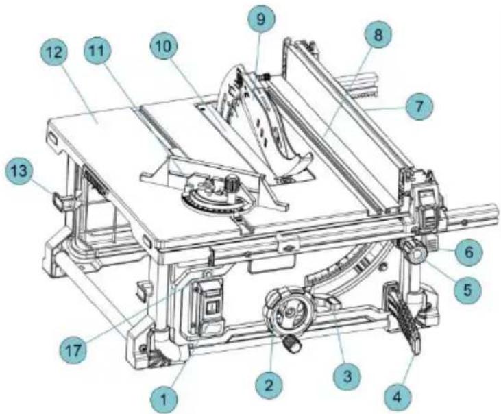
Getting To Know Your Table Saw
1. POWER SWITCH
Switch incorporates a hole for use with a padlock to prevent accidental starting
must always be in place and working properly for all through sawing cuts.
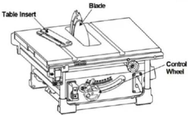
10. · TABLE INSERT
2. ELEVATION WHEEL
Elevates or lowers the blade. Also us tilt the blade 0 to 45 degrees. 11.
Removable for removing or installing a blue and other cutting tools.
11. MITER GAUGE
3. BLADE BEVEL LOCK HANDLE
Locks the blade to desired bevel angle
Head can be locked in the desired posi for crosscutting or mitering by tightening lock knob. ALWAYS SECURELY LOCK WHEN IN USE.
4. PUSH STICK & STORAGE
Allows you to rip smaller pieces with a greater level of safety .
12. stock TABLE
Provides large working surface to port the workpiece .
5. RAIL DRIVING KNOB
Move the fence to the desired
13. CORD WRAP
Allows you to easily secure the cord sc out of the way when transporting or stc
6. RAIL LOCK HANDLE
Allows you to lock the fence at desired dis- tances .
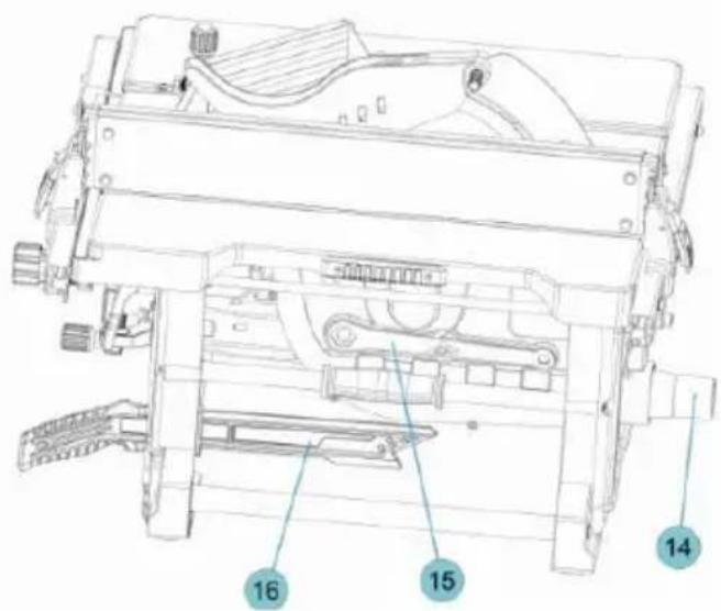
14. DUST PORT/VACUUM HOOK-UP
Removable to clear pieces of wood er trapped inside.
7. RIP FENCE
Provides an auxiliary support (in the lower position) and over-the-table support (upper position). Securely attaches to15 rail with locking latches on both ends.
15.rail\$HEX WRENCH & STORAGE
Hex wrench for adjusting the riving knife/ splitter and various hex heads on the s
8. WORK SUPPORT/AUXILIARY FENCE
Provides support for wider workpieces extending the fence beyond the table
16whenHANDLE
Specifically designed to be be ergonomic and to easily Convenient handling.
9. Blade Guard
Consists of two key elements: Riving and Barrier Guard Device.Blade Guard
17Knife POWER RESET
Used to protect reset after power outage
Unpacking And Checking Contents
WARNING
To avoid injury from unexpected starting orelectrical
shock during unpacking and setting up, do not plug the power cord into a source of power. This cord must remain unplugged whenever you are assembling or making adjustments to the table saw with stand.
Separate all parts from the packing materials and check each one with the illustration and the list of Loose Parts to make certain that all items are accounted for before discarding any packing material (Fig. 3).
WARNING
If any parts are missing, do not attempt to assemble the table saw, plug in the power cord or turn the switch on until the missing parts are obtained and are installed correctly.
| TABLE OF LOOSE PARTS | ||
| ITEM | DESCRIPTION | QTY. |
| 1 | Table Saw | 1 |
| 2 | Dust Chute Elbow | 1 |
| 3 | RIP Fence | 1 |
| 4 | Blade Guard | 1 |
| 5 | Miter Gauge | 1 |
| 6 | Push Stick | 1 |
| 7 | Knob | 1 |
| 8 | Screw | 1 |
| 9 | Allen Wrench | 1 |
| Manual10 | 1 | |
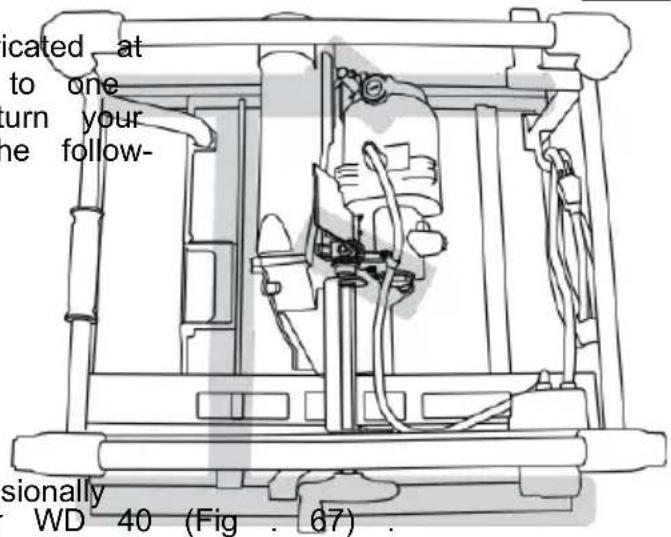
REMOVE CABLE TIE AND STYROFOAM BLOCK
(Used for shipping purpose only)
With the table surface on the ground, locate the cable tie that anchors the motor/blade assembly to the base. Using scissors or wire cutters, cut and remove the cable tie (Fig 4).
Assembly
ATTACHING THE Blade Guard
WARNING To prevent personal inj always disconnect the plug from the power source before attaching or removing the Blade Guard.
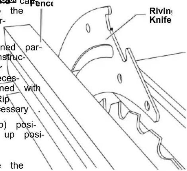
POSITIONING THE RIVING KNIFE
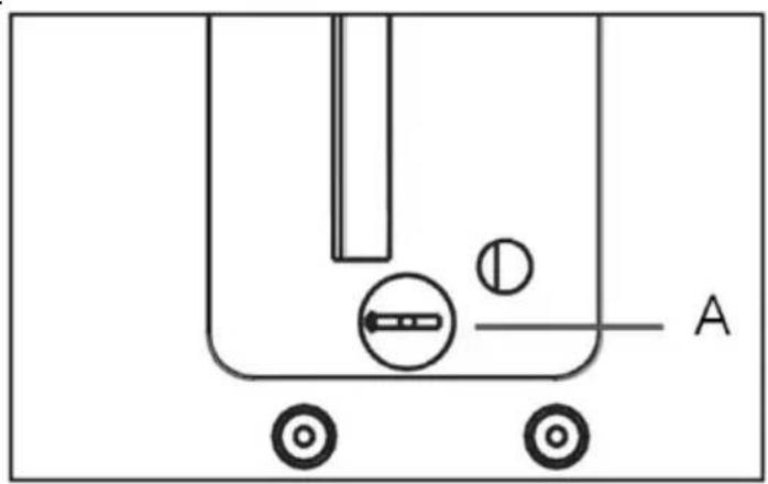
- Remove the table insert using finger hole.
- Raise the blade as high as it will go perpendicular to table ( 0^ on bevel scale) (Fig. 5).
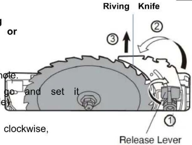
- Rotate the riving knife release lever clockwise, so that it points upward (Fig . 5).
- Pull the riving knife toward the release lever to disengage it from the pins.
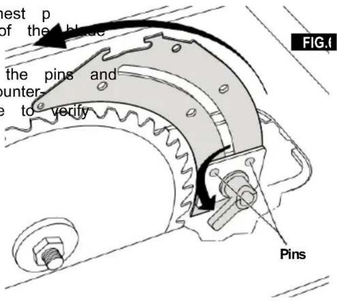
- Slide the riving knife up to positionhighest p so that it is directly over the center of the blade (Fig . 6).
- Align the holes in riving knife with the pins and lock the release lever by rotating it counter-clockwise. Push/pull on the riving knife to verify that it is locked in place (Fig . 6).
- Replace the table insert (Fig . 7)
natural_image
Simple line drawing of a container with wheels and a labeled point A (no text or symbols beyond label)FIG.5
Assembly
ATTACHING THE GUARD ASSEMBLY
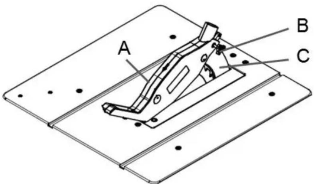
Mount the saw blade guard(A) together with the bolt(B) on top of the riving knife(C), the bolt is firmly seated in the slot of knife(C). Check that the guard assembly is surely connected
Do not screw in the bolt(B) too tightly; blade guard(A) must move freely.
Plug the suction hose onto the suction adapter and the connecting piece of the saw guide that guard(A). Connect a suitable splint the leading onto the suction adapter.
Disassembly is performed in reverse order. Caution! The saw blade guard(A) must be lowered onto the workpiece before starting the sawing operation.
Assembly
REMOVAL AND INSTALLATION
OF THE BLADE
WARNING Disconnect the plug from power source before performing any assembly, adjustment or avoid possible injury.
USING THE CORRECT BLADE
IMPORTANT: The saw blade provided on with the riving knife / splitter, which may be tool has a diameter of 10 inches. When working piece during cutting. One "stabilizer" plate for a replacement blade, select one with made be placed only against the outside of sions close to the original blade. This replacement blade. These plates are not required may not be printed on the blade's packaging. This supplied blade is not, check the manufacturers catalog or website. EVOR offers Premium-Quality Professional saw blades that match the requirements for this tool. You must select a blade with a cover of installation width of .092" or more and a plate (body) thickness .088" or less (Fig . 10).
WARNING To reduce the risk of injury do not use blade "damper s
,"the"stabilizers," or "stiffening collars" on sides of a replacement blade. These are plates positive against the sides of the blade. Reduce deflection that may occur when using saw blades. Use of these devices on both will prevent the blade from being properly a with the riving knife / splitter, which may be working piece during cutting. One "stabilizer" plume be placed only against the outside of replacement blade. These plates are not reaging. the isupplied blade.
CHANGING THE BLADE
NOTE: for clean blade of any excess oil before installation. width ickness
FIG.
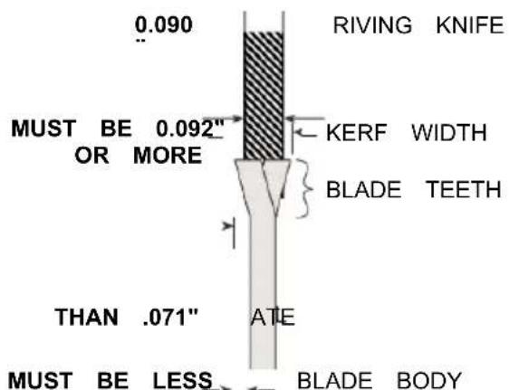
FIG.11
WARNING
To reduce the risk injury do not use extra kehfsaw blades. The kerf of the blade must be .092. Extra thin kerf saw blades (less the may cause the work piece to bind against knife / splitter during cutting. It is that the kerf of the replacement blade saw be .092" or more.
-
To reduce the risk of injury, use the con
-
Turn elevation wheel clockwise until the black up as high as it will go.
-
Removeiv-table insert.
recommended 4. Insert the open-head hex wrench onto the shaft. On which holding the first
wrench, loosen the arbor nut counterclockwise with the ring-head hex wrench.
WARNING
To red ce therisk of injury do noise savblade smade
with a thick body plate. If the replace blade's plate thickness is greater than .071" driving knife / splitter would not properly aid to reduce kickback. The replacement plate thickness must be less than .071"
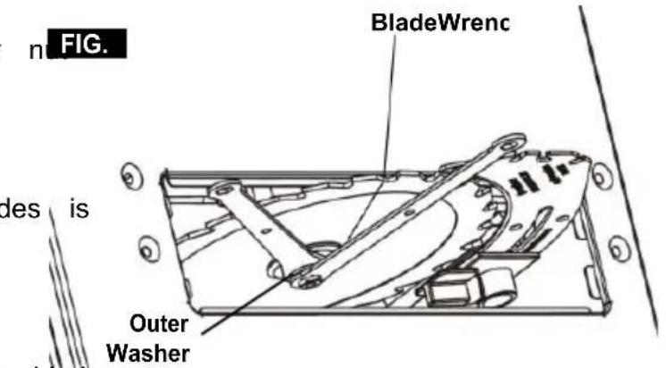
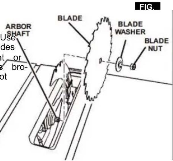
- Remove the arbor nut and outer washer.
Blade saw may now be removed or installed 71," the by sliding it onto or off the arbor shaft. serve as an
6lAssemble the inner washer, newuteblade, o washer and arbor nut as shown. (Fig . 14
Assembly
making certain that the TEETH OF THE ARE POINTING DOWN AT THE
-
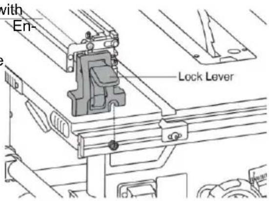
Lower the fence onto the rails and set lock levers on both sides of the fence
-
Ensure that the rail lock paddle is in locked position prior to operating the saw open-head
FRONT OF THE TABLE.
- While holding the arbor shaft with the hex wrench, use the ring-head
hex wrench to securely tighten the arbo clockwise. (Fig . 13)
- Install table insert.
NOTE: The printing on different saw blades is not always on the same side.
To avoid injury from a thrown workpiece, blade part, or blade contact, never operate the saw without the proper insert in place. Use the table insert when sawing. Use the dado insert when using a dado blade.
USING CARBIDE-TIPPED BLADES
Handle carbide-tipped blades carefully . Carbide is very brittle and can be easily damaged . Use caution when you install, use or store the blades . Do not use a carbide-tipped blade that is bent or has bent teeth, or if the blade has cracks, is broken, or has missing/loose carbide tips . Do not operate a carbide-tipped blade faster than its recommended speed . When selecting a blade, ensure ti is rated above 5000 rpm .
Read, understand, and follow all warnings and instructions provided with your carbide-tipped blades.
ATTACHING RIP FENCE FOR USE
-
Ensure that the rip fence lock levers on both sides of the fence are in the released position. FIG.1
-
Align the notch on the rip fence bracket with the bolt heads on the front and rear rails. sure that the flip-over fence will be on the blade-side of the main fence when in its use position. See Fig. 15.
Storage, Transporting, and Mounting
MOUNTING THE TABLE SAW
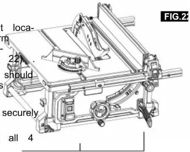
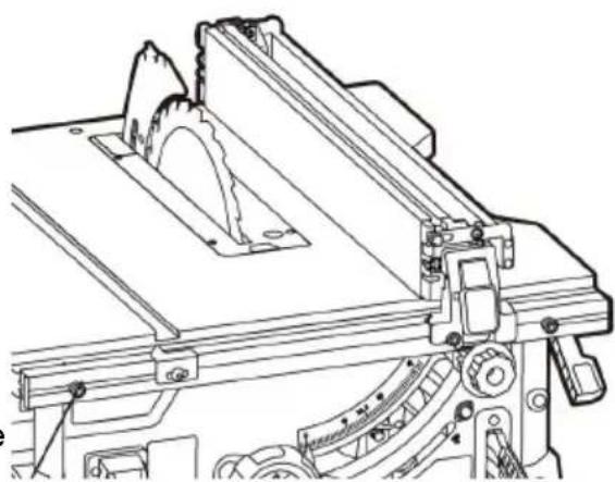
If table saw is to be used in a permanent location, it should be fastened securely to a firm supporting surface such as a stand or workbench, using the four mounting holes (Fig . 22).
- If mounting to a workbench, the base should be securely bolted using the carriage bolts and locking nuts.
- Place the tool on the workbench and securely clamp in place.
-
Use a pencil to mark the locations of all 4 mounting holes.
-
Remove the saw from the workbench drill clearance holes in all 4 locations.
Mounting Bolts
Place tool on workbench and thread n and onto the carriage bolts. Washers may r to be used in order to prevent damage workbench.
Adjustments
ADJUSTING 0 AND 45 DEGREE POSITIVE STOPS
WARNING To prevent personal injury always dis connect the plug
from the power source when making adjustments.
- Turn the elevation wheel clockwise: FIG.2 raise the blade to its maximum height (Fig . 23).
ADJUSTING 0 DEGREE POSITIVE STOP
- Loosen the blade tilt lock handle and push elevation wheel to the left as far as possible; tighten the blade tilt lock handle (Fig. 23).
- Place a combination square (not included) on the table with one end of square against the blade as wsho(Fig . 24), and check to see if the blade is 90 degrees to the table the blade is not 90 degrees to the table loosen the blade tilt lock handle, loosen 90 degree adjustment screw, loosen 90 degree bevel stop cam and push the elevation wheel until the blade is 90 degrees to the table.
- Tighten the blade tilt lock handle, rotate the bevel stop cam until it touches the bevel stop housing, then tighten 90 degrees adjustment screw.
- Loosen the adjustment screw and adjust the pointer to indicate 0 degree on the bevel scale.
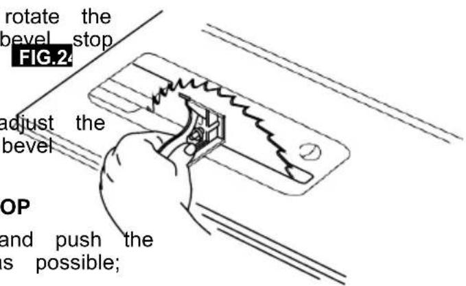
ADJUSTING 45 DEGREE POSITIVE STOP
- Loosen the blade tilt lock handle and push the elevation wheel to the right as far as possible; tighten the blade tilt lock handle.
- Place a combination square (not included) on the table with one end of the sq. FIG.2 against the blade as shown (Fig . 25), and check to see if the blade is 45 degrees to the table. If the blade is not 45 degrees to the table, loosen the blade tilt lock handle, loosen the 45 degradjustment screw, loosen the 45 degree bevel stop cam and push the elevation wheel until the blade is 45 degrees to the table.
- Tighten the blade tilt lock handle, rotate the 45 degree bevel stop cam until it touches the bevel stop housing, then tighten the 45 degree adjustment screw.
Adjustments
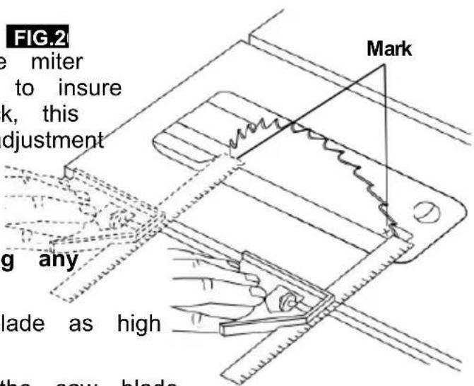
ADJUSTING BLADE PARALLEL TO THE MITER GAUGE SLOTS
The blade was adjusted parallel to the miter gauge slots at the factory. In order to insure accurate cuts and help prevent kickback, this adjustment should be rechecked. If adjustment is necessary, follow the steps below.
WARNING To prevent personal injury always disconnect the plug
from the power source before making any adjustments.
- Turn elevation wheel and raise blade as high as it will go.
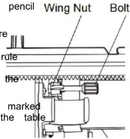
- Select a point on the body of the saw blade that is set to the left when viewing FIG.2 blade from the front of saw, and mark with a pencil (Fig. 26).
- Place the base of a combination square (not included) against the edge of the miter gauge slot, and extend the sliding ru of the square so it just touched the m point on the body of the saw blade at the rear of the table.
- Rotate the blade and check the same marked point of the saw blade at the front of the table (Fig. 26).
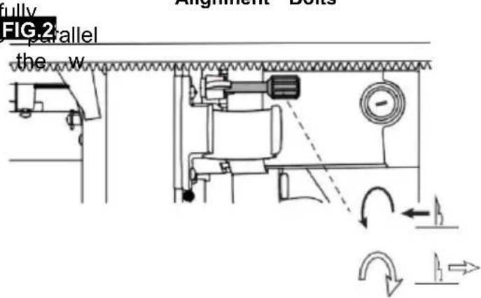
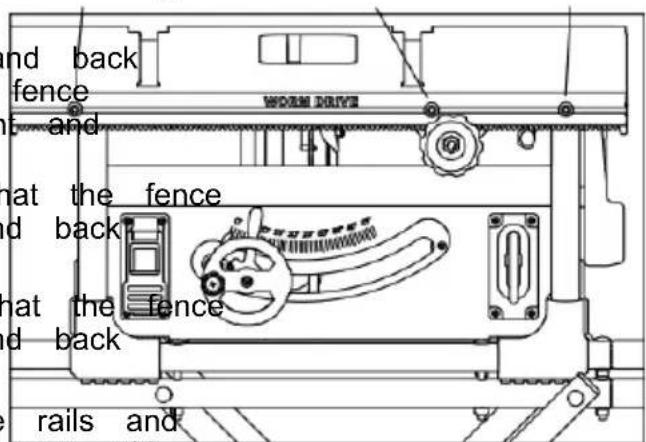
- If the front and back measurements, shown in Figure 26 are not identical, identify the side with the gap. Use the bolt and the wing nut located under the table to adjust the blade position: loosen the wing nut and carefully screw in/out the bolt until the blade is parallel to the miter slot, then securely tighten the w nut.
Alignment Bolts
Adjustments
ALIGNING RIP FENCE
WARNING
To prevent personal injury, always disconnect plug from the power source before making any adjustments.
The fence is properly aligned to the blade the factory and should not re-quire adjustment. This section is intended only for maintenance purposes or when the fence becomes unaligned due to impact. The rip fence must be parallel with the sawblade in order to prevent KICKBACK when ripping.
Your table saw is equipped with a multiple position rack and pinion rip fence. Once adjustments below have been made, the rip fence will self align when the fence is locked. When moving the rip fence, make sure to unlock and lock the fence with the rail lock handle and use the front rail knob to adjust the fence position. NOTE: The blade must be parallel with the miter gauge slots (see "Adjusting Blade Parallel to the Miter Gauge Slots") and be perpendicular to table before proceeding with rip fence align - ment.
WARNING
To prevent personal injury always make sure that the rip fence is locked before making rip cuts.
- Lift both guard barriers to their up locked position (Fig 29).
- Turn the elevation wheel and raise the blade as high as it will go.
- Align the blade to the miter gauge slots per instructions: ADJUSTING BLADE PARALLEL TO THE MITER GAUGE SLOTS .
4 . Right side, position 1 (close to blade), see Fig. 31.
a. Loosen the right side position 1 bolts on the front and back rails so that they can slide freely, approximately 1/2 to 1 turn. Move the bolts to the right by approximately 1/8 inch.
b. Place the fence on the position 1 bolts, but do not secure the latches on the front or back rail.
c . Move the rails so that the position indicator lines up with 0 on the top scale. Lock the rails in place using the rail lock paddle. If anti-kickback pawls
are installed, you will need to raise the right side in order to align the fence v the blade.
d. Slide the fence with the front and back screws towards the blade until the fence touches the blade teeth at the front and back of the blade.
e. Tighten the front bolt. Verify that the fence is still in contact with the front and back teeth of the blade.
f. Tighten the back bolt. Verify that the fence is still in contact with the front and back teeth of the blade.
Latch the fence clamps onto the rails and the ensure that the fence is ll stin contact with the front and back teeth of the bl
natural_image
Technical line drawing of a mechanical machine with cutaway view (no text or symbols)Adjustments
5 . Right side, (further from blade), see .Fig. Place the fence on the right side pos 31. bolts and lock the fence clamps on the
a . Unlatch the fence clamps and remove the fence. b . Loosen the right side position 2 bolts on the front and back rails so that they can slide freely, approximately 1/2 to 1 turn.
c. Using the fence alignment holes in the blade wrench, place the wrench over the right side position 1 bolt on the front rail (already fixed in place by step 4 above) with the second hole roughly aligned with the right side position 2 bolt.
d. Move the dghtposition 2 bolt until the blade wrench slides over the bolt head.
e . Tighten the right side position 2 bolt .
f . Perform steps c through e for the back bolt .
- Left side, see Fig 31.
a. Loosen the left side bolts on the front and back rails so that they can slide freely, approximately 1/2 to 1 turn. Move the bolts so they are approximately 3.5 inches from the left end of the rails.
b. Place the fence on the left-side bolts but do not secure the latches on the front or back rail.
c. Me rails so that the fence touches at least one tooth on the blade. Lock the rails in place using the rail lock paddle. If anti-kickback pawls are installed, you will LeftSide need to raise the right side in order to align the fence with the blade.
d. Slide the fence with the front and back screws towards the blade until the fence touches the blade teeth at the front and back of the blade.
e . Tighten the front bolt . Verify that the is still in contact with the front and back teeth of the eblad
f . Tighten the back bolt . Verify is still in contact with the front teeth of the blade .
g. Latch the fence clamps onto the rails and ensure that the fence is still in contact with the front and back teeth of the blade.
Pointer Adjustment Screws
Right Side 1
Right Side
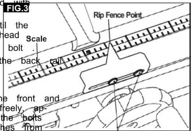
TO SET THE RIP FENCE POINTER:
FIG.3
- Lift both guard barriers to their up locked position.
Adjustments
RIVING KNIFE ALIGNMENT
FIG.32
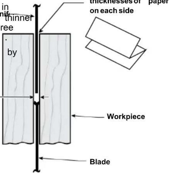
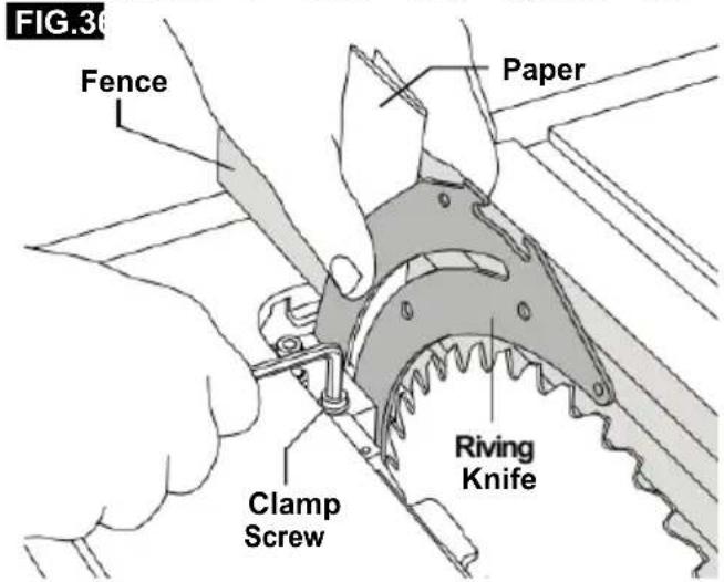
IMPORTANT: The riving knife must always be in line with the saw blade. The riving knife is thinner than the width of the kerf by approximately three thicknesses of paper on each side (Fig . 32).
Note: The kerf is the width of the cut made the teeth on the saw blade.
WARNING To prevent personal injury always dis connect the plug
from the power source before making a key adjustments and when attaching or removing the Blade Guard.
CHECKING RIVING KNIFE ALIGNMENT
WARNING Check riving knife align - ment to the blade periodically and make adjustments as necessary.
Improperly aligned riving knife may result in work piece instability, loss of control, and KICK-BACK. If the riving knife is misaligned, it can not be adjusted, do not attempt to operate the saw. Have a qualified service technician perform riving knife alignment.
- Check that the blade is properly aligned parallel with the miter gauge groove per instructions in "Adjusting Blade Parallel to Miter Gauge slots" and adjust the blade if necessary. Check that the rip fence is aligned with the blade (see instructions in "Aligning Rip Fence") and adjust the rip fence if necessary.
- Raise the blade to the full height (up) position. Raise the riving knife to its full up position (see instructions in "Positioning the Riving Knife"). Remove the guard assembly from the riving knife. Remove the insert plate. (Fig. 33)
- Place the rip fence left side of the table. Carefully move the rip fence against the blade so that the rip fence is parallel to the blade and just touches the tips of the saw teeth. Lock the rip fence and make sure that the front and back of the blade are still touching the rip fence (Fig 33).
Adjustments
-
Using the rip fence as a guide, c ThreeThicknesses ing knife alignment with the plane of the saw of Paper blade. Since the riving knife is thinner by approximately three thicknesses of paper on each side, than the width of the blade's KERF (Fig 32) you must make a temporary paper "spacing gauge". Make two folds in a small piece (6" X 6") of ordinary newspaper to make three thicknesses. Place the paper spacing gauge between the riving knife and the rip fence (Fig 34).
-
Repeat step 4 with the rip fence on the right of the blade and check with paper spacing gauge.
-
If the paper spacing gauge does not fence between the rip fence and the riving knife per steps 4 and 5 above, the riving knife is not correctly aligned with the blade and must be adjusted. If the riving knife needs adjustment proceed to section "Adjusting Riving IfKnife" the riving knife is correctly aligned with the blade then no adjustment is necessary.
NOTE: The riving knife has been properly a at the factory - Check the alignment before making any adjustments.
ADJUSTING RIVING KNIFE
-
Raise the saw blade to maximum height set the bevel angle to 0^ .
-
Remove the barrier guard assembly and
-
Remove the table insert.
-
Place the rip fence on the right side and position 1 and move the fence until it touches the tips of the saw blade, then lock the rails in place.
-
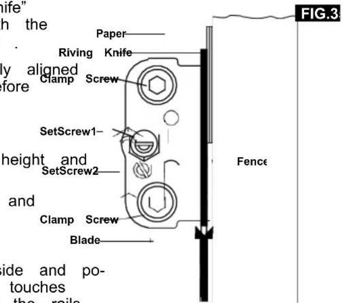
Loosen the hex nut with a 10mm wrench. Slightly loosen the clamping (1/4-1/2 turns) using the 5mm Allen provided. Loosen the screw using a screwdriver (Fig. 35).
-
Make two folds in a small piece 6") to form three layers (Fig . 32) paper is used as a "spacing gauge
NOTE: The spacing instructions above are b open end on using a standard kerf blade (.128" ker screws blade included). If a smaller kerf blade is vrench adjust the paper spacer. For instance, if t the replacement blade is near .100," use 1 ness of paper as a spacer; if the kerf is of se paper thicknesses.
This folded
Adjustments
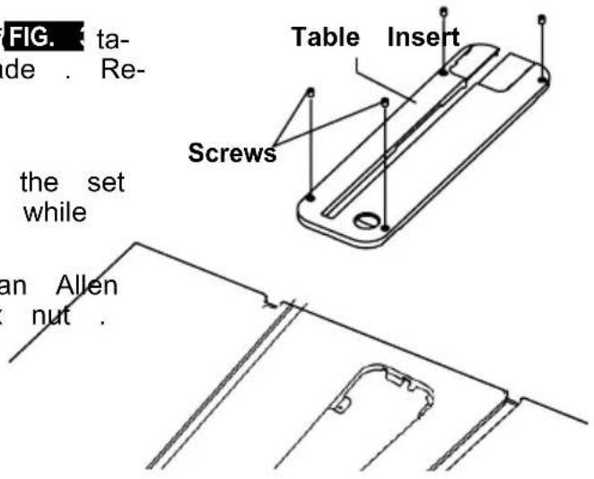
7 . Insert folded paper between riving knife and ADJUSTING THE TABLE INSERT fence . The table insert slot contains four (4)
a. Hold the riving knife and paper first drews for adjusting the height of the table against the fence (Fig . 36) . (Fig . 37) . Place the insert onto the tabl
b. Lightly tighten the clamp screws straightedge (such as the metal ruler from a bination square) across the table top and in c. Remove the paper and move the fence top. If adjustment is necessary, use a 4m away from blade
d. Slowly turn the set screw 1 (for left and down). The insert should be slightly below right adjustment) and set screw 2 (for front at the front and slightly above the ta and rear adjustment) while watching the back riving knife tilt until it is in line with the blade.
e . Recheck squareness of riving knif FIG. table by sliding the fence against blade . Re-adjust if necessary .
- After completing adjustments:
a . Lightly tighten the hex nut (hold the set screw in position with a screwdriver while tightening nut) .
b . Fully tighten clamp screws with an Allen wrench . Then fully tighten the hex nut .
NOTE: Check that the riving knife stays in line with the blade when the blade is tilted at any angle. Replace the Barrier Guard Assembly and before making cuts.
Basic Table Saw Operation
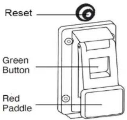
SAFETY POWER SWITCH
NOTE: This table saw has a safety feature that helps prevent accidental starting. When power is cut to the saw, the tool will switch the off mode. Once power is restored, the tool will need to be turned on again.
To turn saw on: Press the green button (Fig . 39) .
To turn saw off: Press the red paddle (which depresses the red off switch underneath) (Fig . 39). RESET BUTTON (POWER RESET)
This saw comes with an overload reset button, If the saw motor overloads, a safety
Mechanism stops the motor automatically due to motor over- loading or low voltage.
To prevent motor overload, reduce on load on motor or check voltage.
Allow motor to cool down, then press the reset button and restart the saw. If the
saw does not restart, wait an additional 5 minutes before restarting.
Basic Table Saw Operation
USING THE Blade Guard
The Blade Guard has been designed for ATTACHING THE GUARD ASSEMBLY modularity, enabling the use of multiple come The Blade Guard must be attached to the binations of the two main components – machines
1) Riving Knife / Splitter, 2) Main Barrier riving knife.
Guard, (Fig . 41) . Addition- ally, the rivNote: The machine should never be used knife can be quickly adjusted to three without this guard in positions, depending on the application its service position.
requirement: through cut (high), non- WARNING: The machine must be through cut (middle), and dado (lowest) . disconnected from the
Any Blade Guard that need to be removed mains supply when installing the blade guard. to complete a cut should be immediately reinstalled when finished. See "Attaching
the Blade Guard" for detailed installation instructions. Always remember that the best accident prevention is the operator's Mount the saw blade guard(A) together with the bolt(B) on top of the riving knife(C), so that the bolt is firmly seated in the slot of the riving knife(C). Check that the guard assembly is seuse of common sense and alertness at allcurely connected times when using the table saw .
natural_image
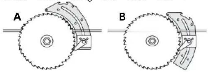
Two mechanical diagrams labeled A and B showing gear meshing or cutting process (no text or symbols present)
Mount the saw blade guard(A) together with the bolt(B) on top of the riving knife(C), so that the bolt is firmly seated in the slot of the riving knife(C). Check that the guard assembly is se-Ipurely connected
Do not screw in the bolt(B) too tightly; the saw blade guard(A) must move freely.
Plug the suction hose onto the suction adap and the connecting piece of the saw blade guard(A). Connect a suitable splint collector onto the suction adapter.
Disassembly is performed in reverse order.
Caution! The saw blade guard(A) must be lowered onto the workpiece before starting the sawing operation.
Basic Table Saw Operation
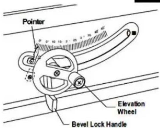
BLADE BEVEL CONTROL
Loosen the blade bevel lock handle counter clock - wise (Fig . 43), slide the elevation wheel until the pointer is at the desired angle and tighten the blade tilt lock handle clockwise.
FIG.43
Basic Table Saw Operation
WORK HELPERS
Before cutting any wood on your saw, study all of the "Basic Saw Operations." FIG.44 Workpiece End
Notice that in order to make some of the cuts, it is necessary to use certain devices, "Work Helpers," like the Push Stick, the Push Block and the Auxiliary Fence, which you can make yourself.
After you have made a few practice cuts, make these "helpers" before starting any projects. Make the "Push Stick" first. (A push stick is included with the).
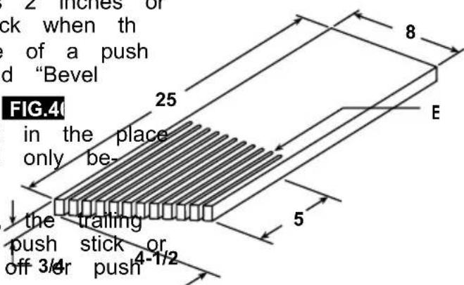
PUSH STICK AND PUSH BLOCK FIG.4
Makethe push stick usinge aof pi¢ x 2 as (Fig . 44) .
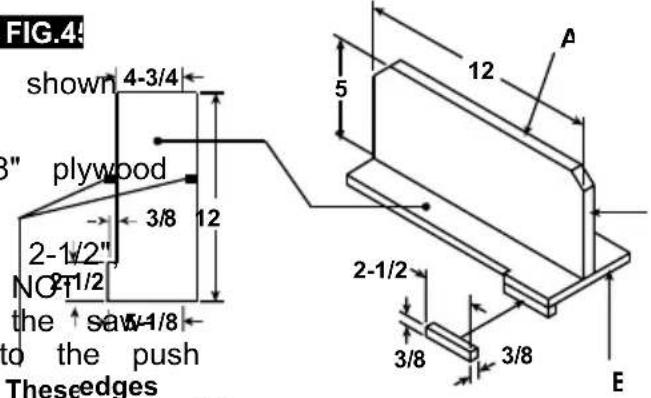
Make the push block using pieces of 3/8" A and 3/4" hardwood B (Fig . 45) .
The small piece of wood, 1/2" x 3/8" x should be GLUED to the plywood... DO USE NAILS. This is to prevent dulling blade in the event you mistakenly cut in block.
Position the handle in the center of the plywood and fasten it together with glue and wood screws.
Use a push stick whenever the fence is 2 inches or more from the blade. Use a push eblock when the operation is too narrow to allow the use of a push stick. For proper use, see "Ripping" and "Bevel Ripping sections."
The push stick or block should be used in the place of the user's hand to guide the material only between the fence and blade.
When using a push stick or push block, end of the board must be square. A block against an uneven end could slip the work away from the fence.
mustbe parallel plywood od screws .
FIG.40
NOTE: All dimensions in inches.
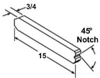
MAKING A FEATHERBOARD
Figure 46 illustrates dimensions for ingaka typical feather board. It should be made from a straight piece of wood that is free of knots or cracks. Kerf E should be about 1/4" apart (Fig . 46).
Basic Table Saw Operation
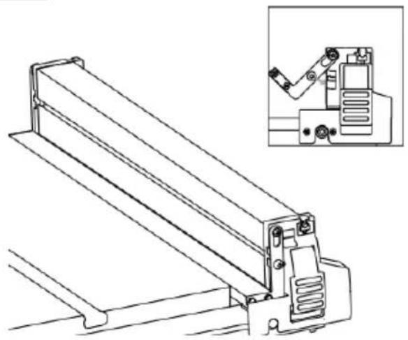
MATERIAL SUPPORT / AUXILIARY FENCEI support is in the stowed position (Fig 1). When the fence is beyond the table-top, ensure an auxiliary fence is required, place the main support in the upper position on both the material support is secured in the lowest back slots (Fig . 47b). To secure fence position in both the front and the back slots when lower the lock handle. The fence is over the table, ensure that the mate-
FIG.47a
natural_image
Technical line drawing of a mechanical device with an inset showing a close-up of its internal components (no text or symbols present)FIG.47

natural_image
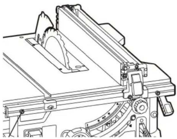
Technical line drawing of a mechanical device with an inset showing a robotic arm (no text or symbols present)USING THE RIP FENCE POINTER
The rip fence pointer shows the distance from the blade to rip fence.
FIG.4
natural_image
Technical line drawing of a mechanical assembly with cutaway view (no text or symbols)Basic Table Saw Operation
WARNING
Always wear hearing pro 10 tion during cutting, and gloves
when handing saw blades .
USING THE RIP FENCE
. Do not pick up small pieces of cut-rial from the table . REMOVE them by ing them OFF the table with a long st Otherwise they could be thrown back at by the rear of the blade .
RIPPING, BEVEL RIPPING, RESAWING AND
RABBETING are performed using the RIP 'FE together with the AUXILIARY FENCE / WORI
SUPPORT, PUSH STICK OR PUSH BLOCK
Do not remove small pieces of cut-of trial that may become TRAPPED inside t blade guard while the saw is RUNNING THIS COULD ENDANGER YOUR HANDS
WARNING
For your own safety, always observe the following safety
precautions, in addition to the safety instructions on Pages 3, 4, 5 & 6. remove the piece.
- Never make these cuts FREEHAND (with- If the workpiece is warped, place the out using the rip fence or auxiliary devices CAVE side DOWN. This will prevent it when required), because the blade could rocking while it is being ripped.
bind in the cut and cause a KICKBACK
RIP FENCE AUXILIARY FACING
- Always lock the rip fence securely when using dado accessories, an auxiliary placing board should be used. This will help
- Remove miter gauge from table during damage to the aluminum fence. The facing operations that utilize the rip fence. should be made of 3/4 inch thick wood (F
- Make sure that the blade guard is installed for Parts Required:
all through sawing type cuts. Replace 3/4 the guard IMMEDIATELY following completion size of resawing, rabbeting, or dadoing operations. Two.
3/4 the thick wood board (solid or plywood) cut size of ons Two · (2) clamps .
- Have the blade extend approximately 1/8" above the upper surface of workpiece tional blade exposure would increase the hazard potential. The facing is made to the same height (2) as the fence and can work with the blade system in place when moving the fence to test the blade, while two clamps to claim
- Do not stand directly in front of the blackboard in wood board to the rip fence. case of a KICKBACK. Stand to either side of
NOTE: The auxiliary facing board, should also be used when cutting material less than 3/
- Keep your hands clear of the blade and out of the path of the blade.
- If the blade stalls or stops while cutting, TURN THE SWITCH OFF before attempting to free the blade.
- Do not reach over or behind the blade to pull the workpiece through the cut, to support long or heavy workpieces, to remove small cut-off pieces of material, or FOR ANY OTHER RISON.
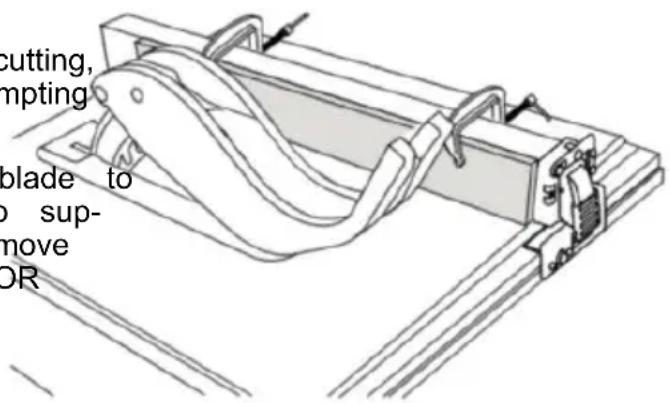
FIG.49
Basic Table Saw Operation
RIPPING
FIG.50
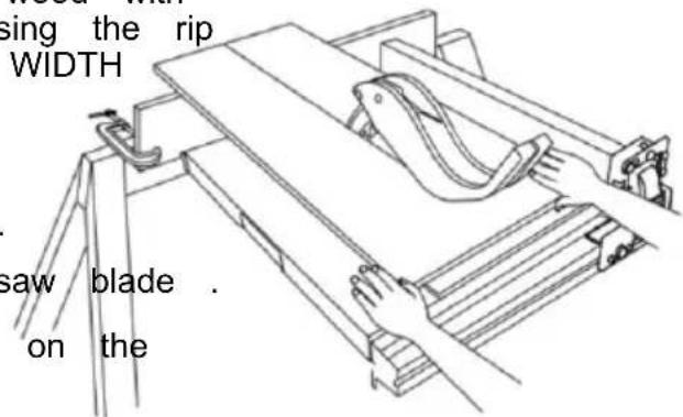
RIPPING is known as cutting a piece of wood with the grain, or lengthwise. This is done using the rip fence. Position the fence to the desired WIDTH OF RIP and lock it in place.
Before starting to rip, be sure:
A . Rip Fence is parallel to saw blade .B . Riving knife is properly aligned with saw blade .
Position the wider portion of the workpiece on the side of the fence.
BEVEL RIPPING
Avoid bevel ripping with the fence on the left side, when possible. When bevel ripping material 6" or mower, use the fence on the right side of the blade ONLY. This will provide more space between the fence and the sawblade for use of a push stick. If the fence is mounted to the left, the sawblade guard may interfere with proper use of a push stick.
When "WIDTH OF RIP" is 6" and WIDER use your RIGHT hand to feed the workpiece, use LEFT hand ONLY to guide the workpiece, do not FEED the workpiece with the left hand (Fig . 50).
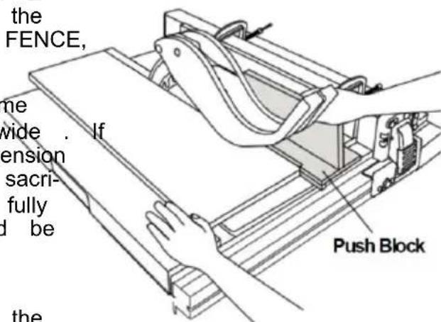
When "WIDTH OF RIP" is 2" to 6" wide USE THE PUSH STICK to feed the(Figor. 51).
When WIDTH OF RIP is NARROWER than 2" the push stick CANNOT be used because the guard will interfere. USE the AUXILIARY FENCE, and PUSH BLOCK.
The auxiliary fence should be used any time the "WIDTH OF RIP" is under 6 inches wide. the "WIDTH OF RIP" is of a smaller dimension than the height of the workpiece, then a sacrificial auxiliary fence of adequate height to fully support the workpiece during the cut should be made and attached to the fence.
Feed the workpiece brand until the end is approximately . 1" from the front edge of the table . Continue to feed using the PUSH BLOCK on top of auxiliary fence UNTIL THE CUT IS COMPLETE (Fig . 52) .
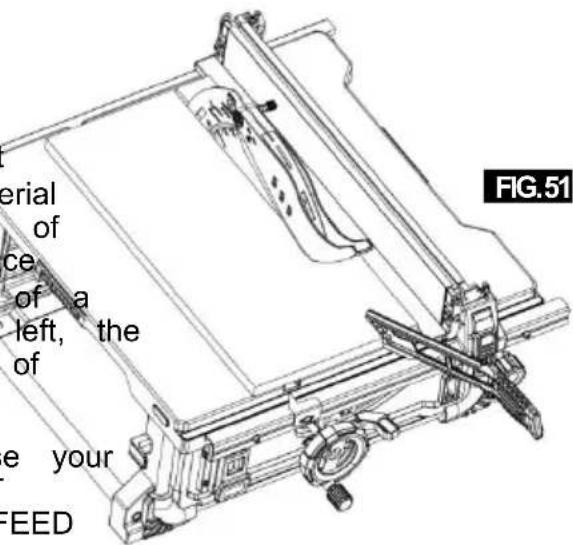
FIG.52
Basic Table Saw Operation
NOTE: When bevel crosscutting, attach the fac CROSSCUTTING, MITER CUTTING, BEVEL so that it extends to the right of the mite CUTTING, COMPOUND MITER CUTTING and use the miter gauge in the groove to when RABBETING across the end of a narrow blade. workpiece, the MITER GAUGE is used . FIG.53
WARNING
For your own safety, always observe the following safety
precautions, in addition to the safety instructions in General Safety Rules, Safety Instructions for Table Saws, and Additional Safety Rules.
Never make these cuts freehand (without using the miter gauge or other auxiliary devices) because the blade could bind the cut and cause a KICKBACK or cause your fingers or hand to slip into the blade.
Always lock the miter gauge securely when in
Remove the rip fence from table during any operations that utilize the miter gauge.
Miter Gauge at 90° can be used from 0 to 15-3/4 inches cross cutting.
When cross cutting with the blade set at 90^ or 45^ to the table, the miter gauge can be used in either slot on the table. When cross cutting and the blade is tilted, use the slot on right side of table where the blade is tilted away from your hands and miter gauge.
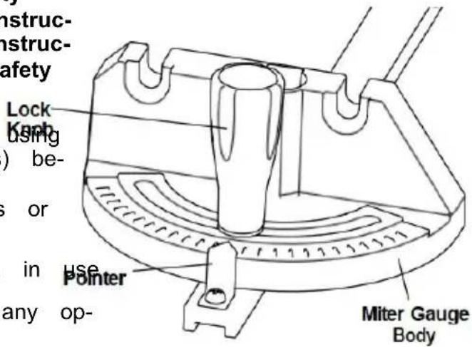
To adjust the miter angle:
Loosen lock knob and set the miter gauge body so that the pointer is at desired angle, then 3 tightening 3" lock knob (Fig . 53) . Board
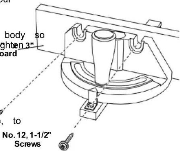
MITER GAUGE AUXILIARY FACING
The miter gauge is designed to accept an Auxiliary Facing with pre-molded holes for fastening a suitable piece of smooth straight wood. Utilize the miter gauge as a template, to attach with proper fasteners (Fig . 54).
Example:
A . Drill 5/32" dia . holes through a board 3/4" thick, 3" high, and desired length .
B . Attach with two No . 12 round head wood screws 1-1/2" long, not included (Fig . 54) .
Be sure that the screws never protrude above the outside surface of facing.
Be sure the facing does not interfere with the proper operation of the saw blade guard.
Basic Table Saw Operation
CROSSCUTTING
CROSSCUTTING is known as cutting wood across the grain, at 90°, or square with TIP. The space between the miter gauge be edge and the flat side of the wood. This is done in the table is held to a minir with the miter gauge set at 90° (Fig . 55). Manufacturing. For maximum accuracy when make sure that the blade guard is installed for all using the miter gauge, always "favor" one s "through sawing" operations (when the sawblade cuts entirely through the thickness of the work- piece). Replace guard IMMEDIATELY after completion of dadoing or rabbeting cuts. The groove.
Have the blade extend approximately 1/8" TIP: Glue a piece of sandpaper to the face top of workpiece. On Add blade exposure would miter gauge head. This will enhance the prwork-increase the hazard potential. piece from "creeping" while it is being cut
Do not stand directly in front of the blade in case of a THROWBACK (small cut-off piece caught by the back of the blade and thrown toward the blade) . Stand to either side of the blade. The miter gauge may be used in either of grooves in the table . Make sure it is loc Groove, hold the workpiece firmly against ga head with your left hand, and grip the lock with your right hand . Keep your hands clear of the blade and out of the path of the blade .
If the blade stalls or stops while cutting, TURN THE SWITCH OFF before attempting to free the workpiece with your right hand and the lock with your left hand.
Do not reach over or behind the blade to pull the workpiece through the ,cuto support long or heavy workpieces, to remove cut-off pieces of material, or FOR ANY OTHER REASON .
Do not pick up small pieces of cut-off material from the table. REMOVE them by pushing them OFF the table with a long stick. Otherwise they could be thrown back at you by the rear of the blade.
Do not remove small pieces of cut-off material that are close to or may become TRAPPED inside the blade guard while the saw is RUNNING. THIS COULD ENDANGER YOUR HANDS or cause a KICKBACK. Tume saw OFF. After the blade has stopped turning, lift the guard and remove the piece.
If the workpiece is warped, place the CONCAYE side DOWN. This will help to prevent it from rocking while it is being cut.
The graduations on the miter gauge provide accuracy for average woodworking. In some cases where extreme accuracy is required, when making angle cuts, for example, make a trial cut and then recheck it with an accurate square or protractor.
Basic Table Saw Operation
REPETITIVE CUTTING
REPETITIVE CUTTING is cutting a quantit pieces the same length without having to each piece (Fig . 56) .
When using the miter gauge in the LEFT groove, hold the workpiece firmly against the miter gauge head with your left hand, and lock knob with your right hand.
When making repetitive cuts from a long piece, make sure it is supported.
When using the RIGHT hand groove, hold the workpiece with your right hand and the lock with your left hand.

Never use the rip fence as a length stop, because the FIG.
off piece could bind between the fence and the blade causing a kickback.
- When making repetitive cuts, clamp a block of wood 3" long to the table at the desired length to act as a length stop.

When clamping the block, make sure that the end of
the block is well in front of the sawblade. Be sure that it is clamped securely.
- Slide the workpiece along the miter gauge until it touches the block, then hold it securely.
- Make the cut, pull the workpiece back, then CROSSCUTTING is the same as crosscutting push the cut-off piece off the table withting length that the wood is also cut at push stick. DO NOT ATTEMPT TO angle other than 90° with the flat side of UP AS THIS COULD ENDANGER YOUR (Fig . 58). HANDS. Adjust the blade to the desired angle
FIG.
natural_image
Line drawing of a hand using a tool to cut or mark a piece of paper (no text or symbols present)MITER CUTTING
Adjust the blade to the desired angle.
Use the Miter Gauge in the groove to the or the LEFT of the blade.
FIG.58
natural_image
Line drawing of a hand using a saw to cut a piece of wood, no text or symbols presentCOMROUND MITER CUTTING
MITER CUTTING is cutting wood at an angle other than 90° with the edge of the wood. the same procedure as you would for cross-section (Fig . 57). tion
Adjust the miter gauge to the desired a lock it.
The miter gauge may be used in either grooves in the table.
ROSMAROUND MITER CUTTING is a combination of miter cutting and bevel crosscutting cut is made at an angle other than 90° t the edge and the flat side of the wood.
Adjust the miter gauge and the blade to the desired angle and make sure that miter gauge is locked.
Basic Table Saw Operation
NON THROUGH SAWING
RABBETING
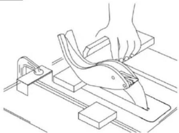
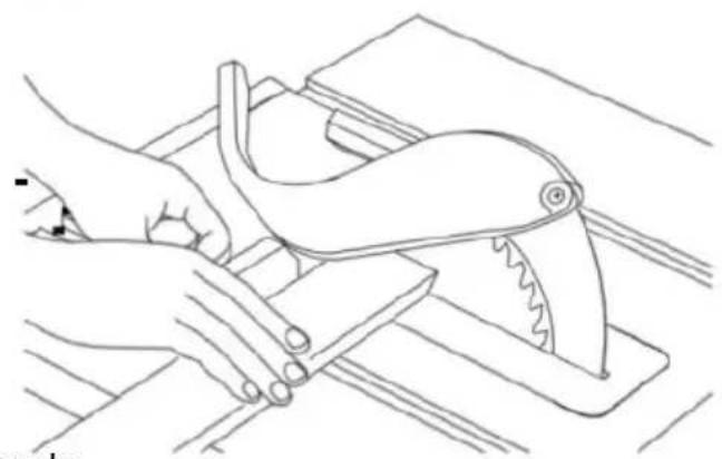
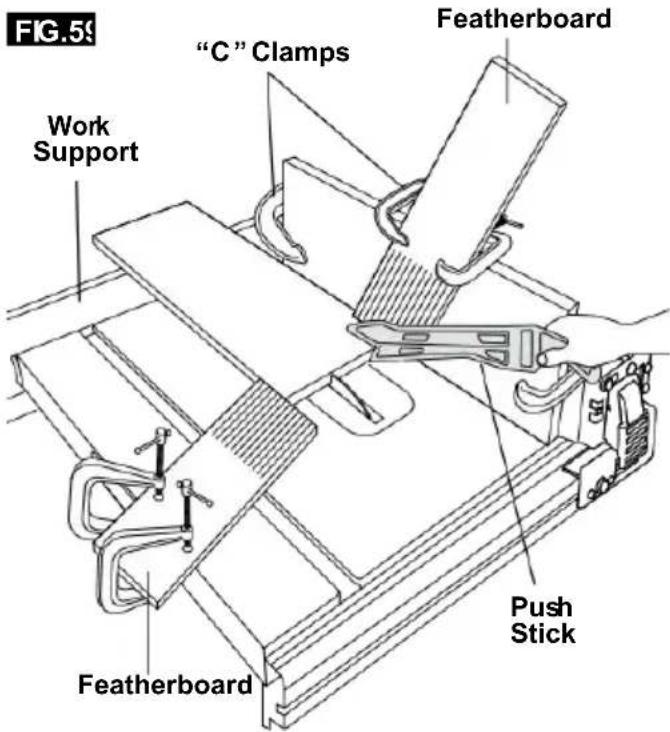
Add an 8" high flat facing board to the RABETINGe is cutting out a section of the full length of the fence (Fig . 59) . of a piece of material, across an end or
Making a RABBET requires cuts that do not the way through the material. Therefore, the Blade Guard must be removed.
- Remove blade guard.
-
For rabbeting along an edge (long way workpiece) as shown, add a facing approximately as high as the workpiece is wide the rip fence. Adjust the rip fence and to the required dimensions, then make the first cut with the board flat on the table, lowing the set-up shown in Fig. 60. second cut with the workpiece on its edge Follow all precautions, safety instructions, and operation instructions as for ripping or type operations, including feather boards and push stick, etc.
-
For rabbeting across an end, for work 1/2" and narrower make the rabbet cut with board flat on the table. Using the miter fitted with a facing, follow the same procedures
Use feather boards for all "Non Through Sawing" operations (when the sawblade gu must be removed). feather boards are keep the work in contact with the fence table as shown, and to stop kickbacks.
and instructions for crosscutting making suc- cessive cuts across the width of the work used to obtain the desired width of cut. DO N and the the rip fence for rabbeting across the er
Mount feather boards to the fence and as shown, so that the leading edges of feather- boards will support the workpiece
- INSTALL Blade Guard IMMEDIATELY UPON table COMPLETION OF RABBET-ING the OPERATION until
the cut is complete and the workpiece has Rabbet cuts can also be made in one pass been pushed completely past the cutter workpiece over the cutter using the dado h (sawblade, dado head, etc.) with a push stick, as
in ripping .
FIG.60
Before starting the operation (with the saw turned "OFF" and the cutter set below the table surface);
A . Install feather boards so they exert pressure on the workpiece; BE POSITIVE THEY ARE SECURELY ATTACHED .
B. Make sure, by trial, that the feather boards will stop a kickback if one should occur.
Feather boards are not employed during non through sawing operations when using the miter gauge.
REPLACE THE Blade Guard AS SOON AS THE NON THROUGH SAWING OPERATION IS COMPLETE .
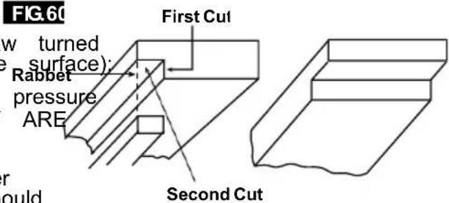
RABBETINGALON
THE EDGE
RABBETINGACROSS
THE END
Basic Table Saw Operation
SPECIAL
CUTTING TECHNIQUES
CUTTING
METALS AND MASONRY

Do not attempt to perform cuts not covered in this

This table saves not recommended focutting met
manual unless you are thoroughly familiar, such as aluminum or copper, even with procedures and fixturing. These types of materials include, but are not limited to, tapered cuts and complex non-through cutting. This table saw is a highly versatile tool, capable of WARNING. This table saw is not commended for cutting any performing a wide range of highly specialized inventory material, even with abrasive cut-cuts that cannot be covered in this manual wheels.
See your local library for books on woodworking techniques, such as: The Complete Book of Stationary Power TooTechniques by R .J . De Christoforo or Table Saw Techniques by R . Cliffe .
LUBRICATION
FIG.
The gear case has been completely lubricated at the factory. However, after six months to one year, depending upon use, it's wise to return your tool to the nearest Service Center for the following:
- Brushes replaced .
- Parts cleaned and inspected .
- Relubricated with fresh lubricant.
• Electrical system tested. - All repairs .
The following parts should be oiled occasionally with SAE No . 20 or No . 30 oil, or WD
- Elevation, support rods, and gears
- Sliding rails and supports.
- Table locking cams (Front & Rear).
Maintaining Your Table Saw
Danger!
Always pull out the mains power plug starting any cleaning work.
1. Cleaning
- Keep all safety devices, air vents and motor housing free of dirt and dust as as possible. Wipe the equipment with a cloth or blow it with compressed air at low pressure.
• We recommend that you clean the d immediately each time you have finished using it.
- Clean the equipment regularly with a cloth and some soft soap. Do not use cleaning agents or solvents; these could attack the plastic parts of the equipment. Ensure that no water can seep into the The ingress of water into an electric tool increases the risk of an electric sh
2. Carbon brushes
before case of excessive sparking, have the carbon brushes checked only by a qualified electrician.
Danger! The carbon brushes should not be replaced by anyone but a qualified electrician.
3. Maintenance
There are no parts inside the equipment which require additional maintenance.
4. Ordering replacement parts:
Please quote the following data when noistering replacement parts:
- Type of machine
• Article number of the machine
• Identification number of the machine - deReplacement part number of the part required
Troubleshooting
WARNING
Turnswitch“OFF”andalwaysremoveplugfromthepowersourcebeforetroubleshootin
| PROBLEM | CAUSE | SOLUTION |
| Saw willnotstart | Power cord isnot plugged in. Plug sawin. | |
| Fuseorcircuit breakertripped. Replace fuseorreset tripped circuit breaker. | ||
| Corddamaged. | HavecordreplacedbyanAuthorizedVEVOR ServiceCenter orServiceStation. | |
| Burned outswitch. | HaveswitchreplacedbyanAuthorizedVEVOR ServiceCenter orServiceStation. | |
| Bladedoesnotcomeuptospeed | Extension cordtoo lightor tooloReplace withadequatecord. | |
| Lowsupply voltage. | Contactyourelectric company. | |
| Excessive vibration | Failure totighten bevellockhandSee“Getting ToKnowYourTableSaw” section. | |
| Bladeout ofbalance. Discard Bladeanduse different blade. | ||
| Saw not mounted securelytotighten all mounting hardware, See the Table Saw” section. | ||
| ArborNut not tight. | See“Assembly” section, “Changing The Blade | |
| Cutbinds,burns,stallsmotor whenripping | Dull blade with impropertooth set. Sharpenor replaceblade. | |
| Warpedboard. | Makesure concaveorhollow sideis facing “DOWN” and feed slowly. | |
| Ripfence not parallel toblade. | See “Adjustments” section “Aligning Rip Fence.” | |
| Riving knifeout ofalignment. | See “Adjustments” section,“Riving knife alignment.” | |
| Cutnottrueat90° or45°positions | Alignment screwsnot adjusted properly. | See“Adjustments” section, “Adjusting Blade Parallel to Miter Gauge Slots.” |
| Plasticmeltsorbladetipsoverheatwhen cutting | Feedrate to high. | Slow feedratethroughblade. |
| Blades tip not sharp Sharpenor replaceblade | ||
| Tiltlockhandle elevation wheel hard tomove | Bevellockhandlenotloosenedwhen making tilt adjustment. | See“GettingToKnowYourTableSaw” section, “Blade Tilt Lock Knob.” |
| Sawdustondepthscrew threads. | See “Maintaining Your Table Saw” section, “Lubrication.” | |
| CircuitBreaker Trips | Circuit breaker trips repeatedlyReplace the blade with a new blade. Red force applied to workpiece during cutting. | |
TECHNICAL DATA
ACMotor....220-240V\~ 50Hz
Power....1800W
Cutting-OffWheel....Ø254xØ30x2.8mm
IdleSpeedn0 4400RPM
NumberOfTeeth....40
CuttingHeightMax....85mm/ 90°.
60mm/45°
TiltingSawBlade......infinite 0 - 45°
ExtractorSocket.... 035mm
Weight....approx.19.3kg
OperatingmodeS625%:Continuousoperationwithidi(cycletime10 minutes).
Toensurethat themotordoes notbecomeexcessively hot,itmayonlybeoperated
for25%ofthecycle atthespecifiedratingandmustthen
beallowedtoidlefor75%
ofthecycle.
Danger!
Soundandvibration
Soundandvibrationvaluesweremeasuredin accordancewithEN61029.
LpAsoundpressurelevel 91dB(A)
KpAuncertainty 3dB
LWAsoundpowerlevel.....104dB(A)
KWAuncertainty....3 dB
Thequotedvaluesareemissionvaluesandnot necessarilyreliableworkplacevalues.
Although thereis acorrelation between emission and
immissionlevelsitisimpossibleto drawanycertain
conclusionsasto theneedforadditionalprecautions.
Factorswith a potentialinfluenceontheactualimmission levelattheworkplace
cludetheduration of impact, the type of room, and other sources of noise, etc.,
e.g. thenumberofmachinesandotherneighboring operations. Reliable workplace
valuesmayalsovaryfromcountrytocountry.Withthis
information, theusershould
atleastbeabletomakeabetterassessment of the dangersandrisks involved.
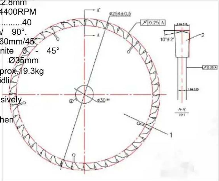
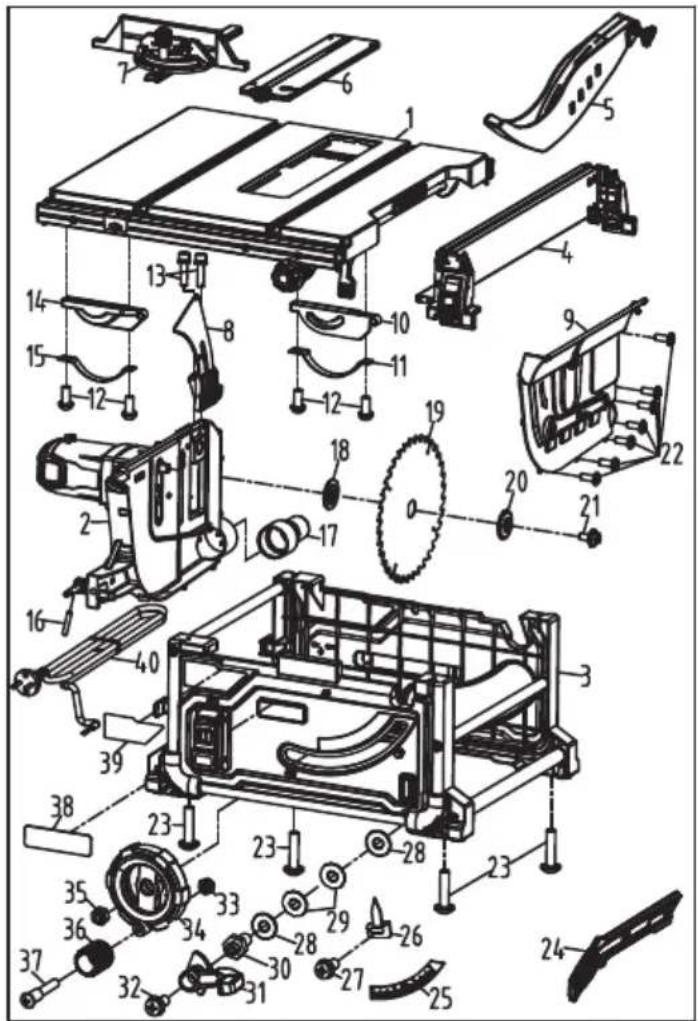
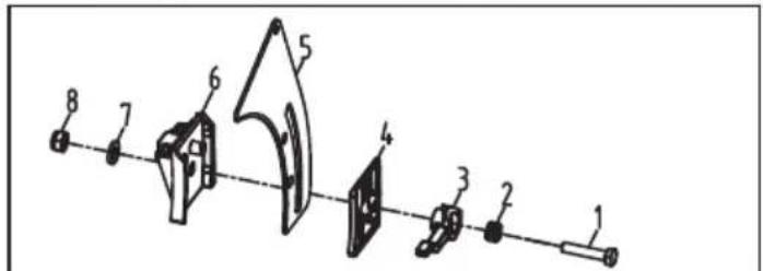
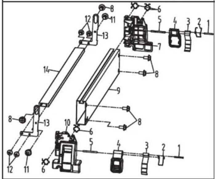
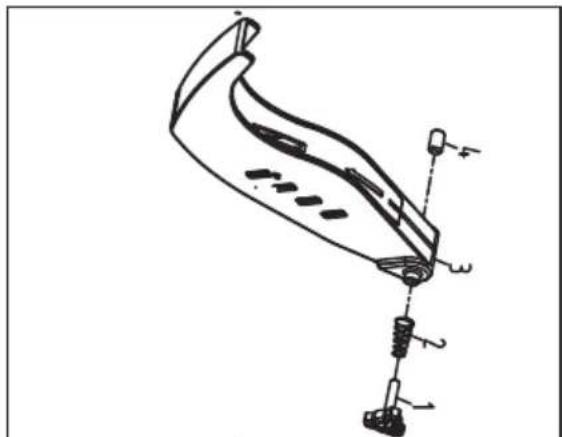
natural_image
Technical line drawing of a mechanical component with labeled parts (no readable text or symbols)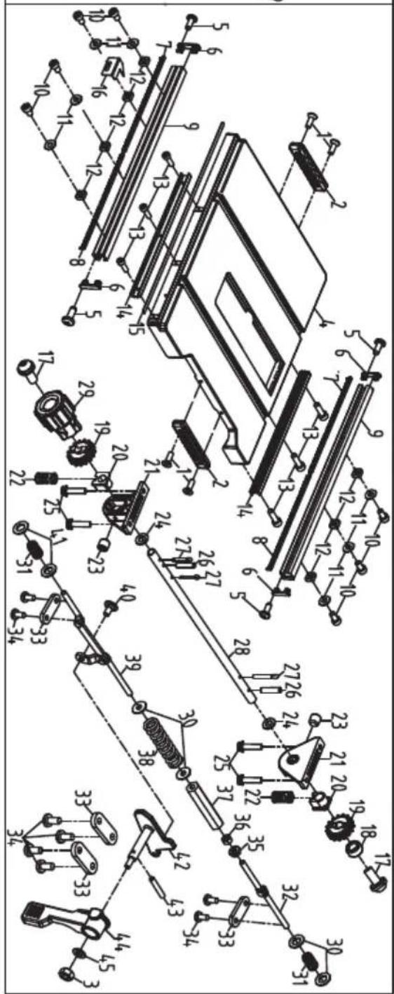

VEVOR®
TOUGH TOOLS, HALF PRICE
Technical Support and E-Warranty Certificate www.vevor.com/support
VEVOR®
TOUGH TOOLS, HALF PRICE
natural_image
Technical line drawing of a mechanical machine with no visible text or symbolsBESOIN D'AIDE? CONTACTEZ-NOUS!
natural_image
Icon of a person wearing glasses inside a circle (no text or symbols)
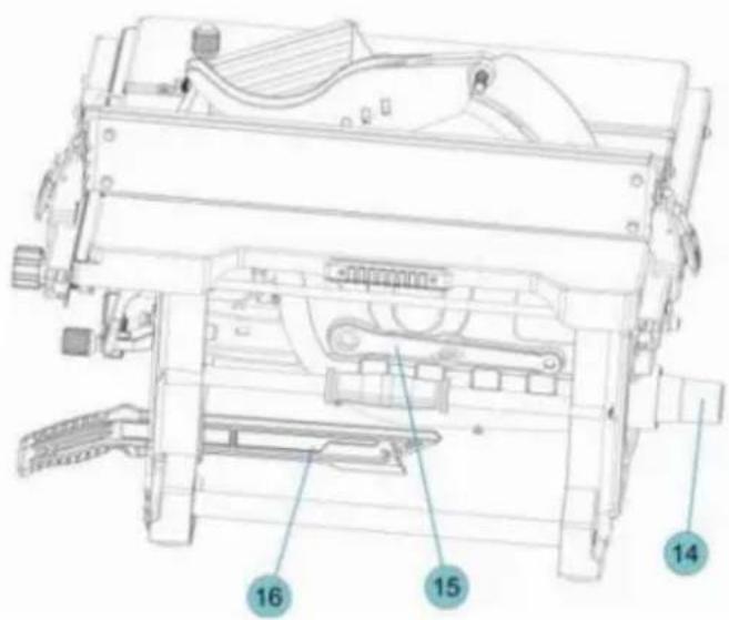
shock during unpacking and setting up, do
Si un t parts aret mélangend o not at empt to un ssemble th e table saw, plug in the power cord or turn the switch on until the missing parts are obtained
natural_image
Pure diagram of a container with wheels and a labeled section A, no text or symbols presentFIG.5

FIG.15
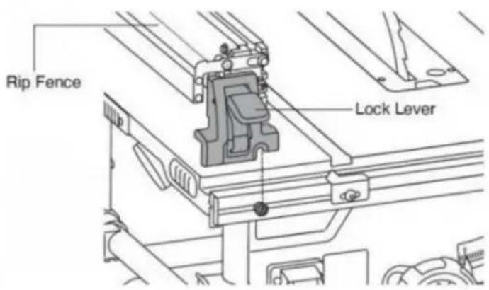
natural_image
Technical line drawing of a mechanical assembly with no visible text or symbolsBoulons de
natural_image
Line drawing of a hand using a tool to cut or mark a piece of wood, no text or symbols presentFIG.25
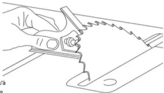
natural_image
Line drawing of a hand using a pliers to cut a saw blade (no text or symbols)Ajustements
RÉGLAGE DE LA LAME PARALLÈLE À LES FENTES DE LA JAUGE À ONGLET
Ajustements
ALIGNEMENT DU GUIDE DE RENFORCEMENT
AVERTISSEMENT
natural_image
Technical line drawing of a mechanical cutting machine with no visible text or symbolsAjustements
natural_image
Two mechanical diagrams showing gear meshing and cutting process (UN vs B), no text or symbols present.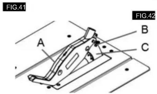
FIXATION DE L'ENSEMBLE DE PROTECTION
AIDES AU TRAVAIL
natural_image
Technical line drawing of a mechanical device with an inset showing a close-up of its internal components (no text or symbols)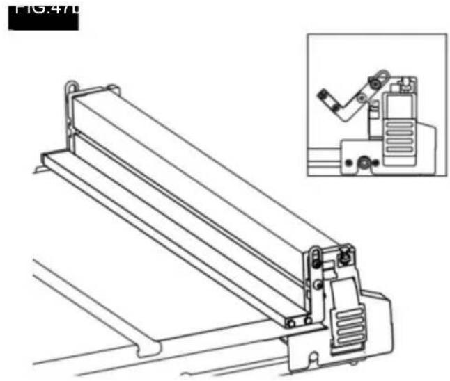
natural_image
Technical line drawing of a mechanical device with an inset showing a bracket assembly (no text or symbols)UTILISATION DU POINTEUR DE GUIDE DE RIPPAGE
natural_image
Technical line drawing of a mechanical assembly with cutaway view (no text or symbols)natural_image
Technical line drawing of a mechanical clamp or bracket assembly (no text or symbols)
DÉCHIRURE
FIG.50
natural_image
Line drawing of a mechanical assembly with hands operating a workpiece (no text or symbols)DÉCHIRURE EN BISEAU
FIG.51
natural_image
Technical line drawing of a mechanical assembly with no visible text or symbolsFIG.52
natural_image
Line drawing of hands using a tool to cut or spread a piece of material on a cutting board (no text or symbols)FIG.55
COUPE RÉPÉTITIVE
natural_image
Line drawing of a hand using a tool to cut or spread a rectangular block, with no text or symbols present.COUPE À ONGLET
natural_image
Line drawing of hands using a tool to cut or spread a piece of paper (no text or symbols)TRONÇONNEUSE EN BISEAU
natural_image
Line drawing of hands using a manual saw to cut a piece of wood (no text or symbols)COUPE À ONGLET COMPOSÉ
natural_image
Technical line drawing of a mechanical assembly with no visible text or symbols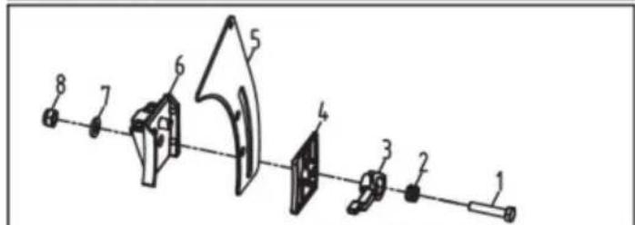


natural_image
Technical line drawing of a mechanical component with labeled parts (no readable text or symbols)

VEVOR®
TOUGH TOOLS, HALF PRICE
natural_image
Technical line drawing of a mechanical machine with no visible text or symbolsnatural_image
Icon of a person wearing glasses inside a circle (no text or symbols)

Wonn irgendoin parts arund mischen, do not at empt to A ssemb das the table saw, plug in the power cord or turn the switch on until the missing parts are obtained
natural_image
Simple line drawing of a container with wheels and a labeled point A (no text or symbols beyond label)Montage
natural_image
Technical line drawing of a mechanical assembly with no visible text or symbolsnatural_image
Line drawing of a hand using a pliers to cut a saw blade (no text or symbols)Anpassungen
Anpassungen
natural_image
Technical line drawing of a mechanical cutting machine with no visible text or symbolsAnpassungen
natural_image
Mechanical gear assembly diagram showing a cam and wheel system (no text or labels)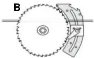
natural_image
Diagram of a gear and cam mechanism (no text or symbols)Abb.41
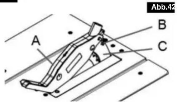
natural_image
Technical line drawing of a mechanical device with an inset showing a close-up of its internal components (no text or symbols present)ADD.471

natural_image
Technical line drawing of a mechanical device with an inset showing a close-up of its component (no text or symbols present)natural_image
Technical line drawing of a mechanical assembly with no visible text or symbolsnatural_image
Technical line drawing of a mechanical clamp or bracket assembly (no text or symbols)
natural_image
Technical line drawing of a mechanical assembly with hands operating a workpiece (no text or symbols)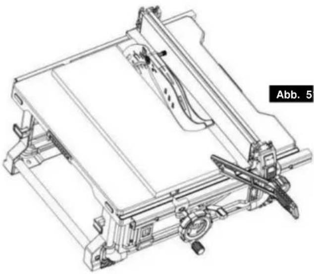
natural_image
Technical line drawing of a mechanical assembly with no visible text or symbolsAbb. 5

natural_image
Line drawing of hands using a tool to cut or spread materials on a cutting board (no text or symbols)FIG. 55
natural_image
Line drawing of a hand using a tool to cut or spread a block, with no text or symbols present.Gehrungsschnitt
natural_image
Line drawing of hands using a tool to cut or spread a piece of material on a flat surface (no text or symbols)FASENKREISSCHNITT
natural_image
Line drawing of hands using a manual tool to cut a piece of wood or paper (no text or symbols present)Gehrungsschnitt
natural_image
Technical line drawing of a mechanical assembly with no visible text or symbols
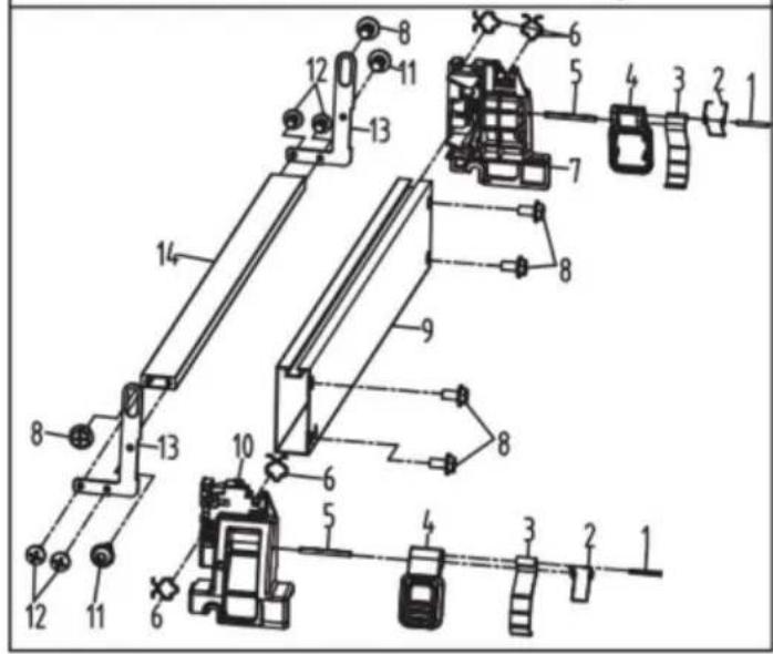

natural_image
Technical line drawing of a mechanical component with labeled parts (no readable text or symbols)
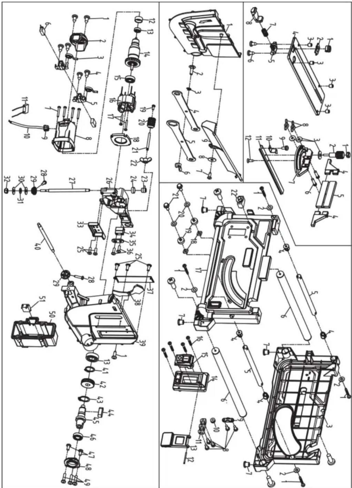
VEVOR®
TOUGH TOOLS, HALF PRICE
natural_image
Technical line drawing of a mechanical machine with no visible text or symbolsLaboratories e la Canadian
Standards Association. II
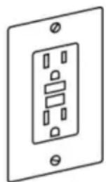
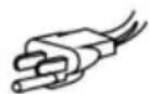
natural_image
Simple icon of a person wearing glasses inside a circle (no text or symbols)
AVVERTIMENTO

table saw, plug in the power cord or turn the switch on until the missing parts are obtained
natural_image
Pure diagram of a container with wheels and a labeled section A, no text or symbols presentFIGURA 5
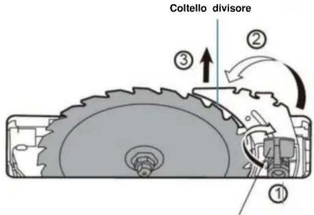
Release Lever
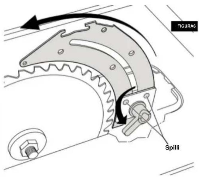
Assemblea
natural_image
Technical line drawing of a mechanical assembly with no visible text or symbolsnatural_image
Line drawing of a hand using a power tool to cut a piece of paper or plastic (no text or symbols present)FIGURA25

natural_image
Line drawing of a hand using a pliers to cut a sheet metal (no text or symbols)Regolazioni
REGOLAZIONE DELLA LAMA PARALLELA A LE FESSURE DEL CALIBRO ANGOLARE
natural_image
Technical line drawing of a mechanical cutting machine with no visible text or symbolsRegolazioni
natural_image
Diagram of a mechanical gear assembly with teeth and a central hub (no text or symbols)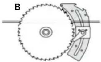
natural_image
Diagram of a gear and cam mechanism with labeled component B (no text or symbols present)
natural_image
Technical line drawing of a mechanical device with an inset showing a close-up of its internal components (no text or symbols present)FIGURA471
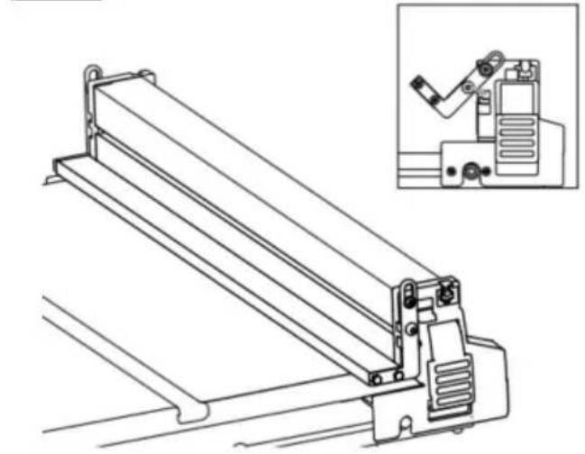
natural_image
Technical line drawing of a mechanical assembly with an inset showing a robotic arm (no text or symbols present)UTILIZZO DEL PUNTATORE DELLA GUIDA PARATIA
natural_image
Technical line drawing of a mechanical assembly with no visible text or symbolsnatural_image
Technical line drawing of a mechanical clamp or bracket assembly (no text or symbols)natural_image
Line drawing of a mechanical assembly with hands operating a workpiece (no text or symbols)
natural_image
Technical line drawing of a mechanical assembly with no visible text or symbolsFIGURA52
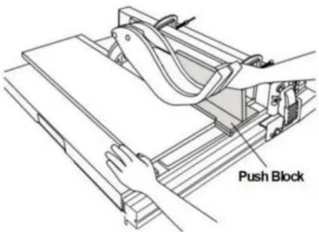
natural_image
Line drawing of hands using a tool to cut or spread a piece of material on a flat surface (no text or symbols)FIG.55
natural_image
Line drawing of a hand using a tool to cut or spread material on a cutting board (no text or symbols)TAGLIO A QUADRETTI
natural_image
Line drawing of hands using a tool to cut or spread a piece of paper (no text or symbols present)TAGLIO TRASVERSALE SMUSSATO
natural_image
Line drawing of hands using a manual saw to cut a piece of wood (no text or symbols)natural_image
Technical line drawing of a mechanical assembly with no visible text or symbols


natural_image
Technical line drawing of a mechanical component with labeled parts (no readable text or symbols)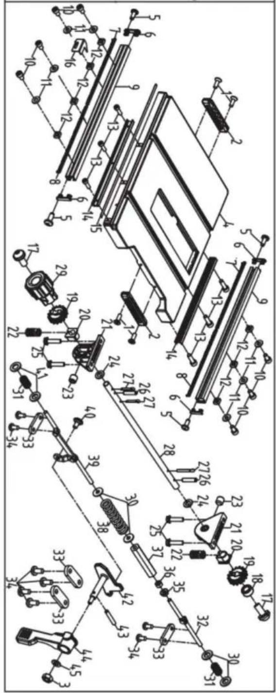

VEVOR®
TOUGH TOOLS, HALF PRICE
natural_image
Technical line drawing of a mechanical machine with cutaway view (no text or symbols)natural_image
Icon of a person wearing glasses inside a circle (no text or symbols)ADVERTENCIA

Si alguna parts ary mezclarg d o not at t empt to a ssemb el th e table saw, plug in the power cord or turn the switch on until the missing parts are obtained
natural_image
Pure diagram of a container with wheels and a labeled point A, no text or symbols presentFigura 5
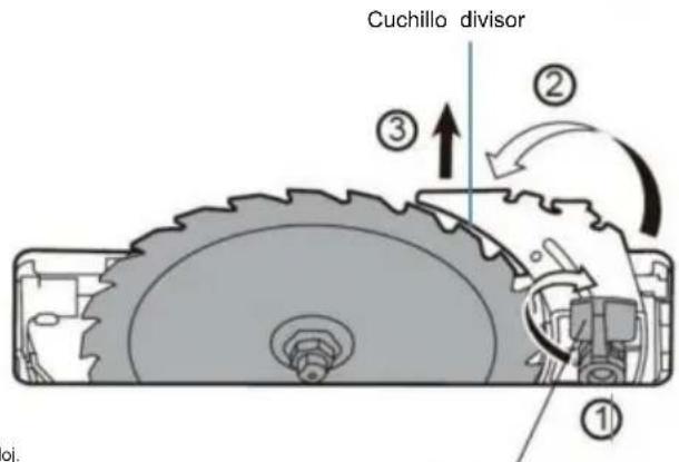
Release Lever
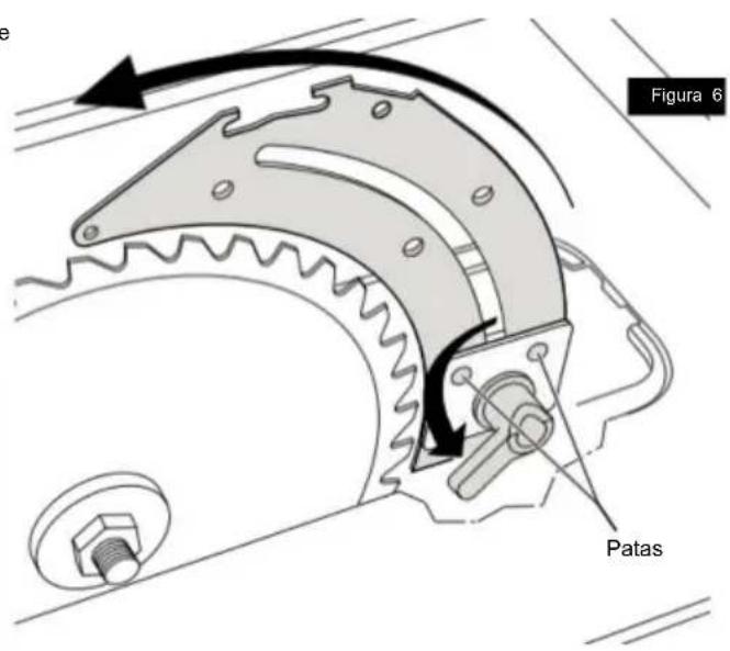
Asamblea
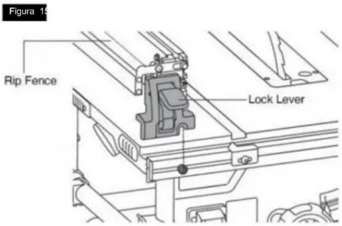
natural_image
Technical line drawing of a mechanical assembly with no visible text or symbolsPernos de montaje
natural_image
Technical schematic of a mechanical assembly with no visible text or symbols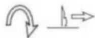
Ajustes
natural_image
Technical line drawing of a mechanical cutting machine with no visible text or symbolsAjustes
natural_image
Two mechanical diagrams labeled A and B showing gear meshing or cutting process (no text or symbols present)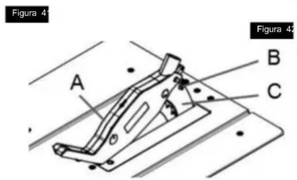
natural_image
Technical line drawing of a mechanical device with an inset showing a close-up of its internal components (no text or symbols present)
natural_image
Technical line drawing of a mechanical assembly with an inset showing a robotic arm (no text or symbols present)USO DEL PUNTERO DE LA GUÍA DE CORTE AL HILO
natural_image
Technical line drawing of a mechanical assembly with cutaway view (no text or symbols)natural_image
Technical line drawing of a mechanical clamp or bracket assembly (no text or symbols)natural_image
Line drawing of a mechanical assembly with hands operating a workbench (no text or symbols)
natural_image
Technical line drawing of a mechanical assembly with no visible text or symbolsFigura 52

natural_image
Line drawing of hands using a tool to cut or spread a piece of material on a cutting board (no text or symbols)FIG.55
natural_image
Line drawing of a hand using a tool to cut or mark a piece of material on a flat surface (no text or symbols)CORTE A INGLETE
natural_image
Line drawing of hands using a tool to cut a piece of material on a flat surface (no text or symbols)CORTE TRANSVERSAL BISELADO
natural_image
Line drawing of hands using a manual saw to cut a piece of wood (no text or symbols)CORTE DE INGLETE COMPUESTO
natural_image
Technical line drawing of a mechanical assembly with no visible text or symbols


natural_image
Technical line drawing of a mechanical component with labeled parts (no readable text or symbols)

VEVOR®
TOUGH TOOLS, HALF PRICE
natural_image
Technical line drawing of a mechanical machine with no visible text or symbolsPOTRZEBUJESZ POMOCY? SKONTAKTUJ SIĘ Z NAMI!
natural_image
Icon of a person wearing glasses inside a circle (no text or symbols)OSTRZEŻENIE

table saw, plug in the power cord or turn the switch on until the missing parts are obtained i są zainstalowane prawidłowo.
natural_image
Pure diagram of a container with wheels and a labeled section A, no text or symbols presentRys.5
natural_image
Technical line drawing of a mechanical assembly with no visible text or symbolsŚruby montażowe
REGULACJA 0 I 45 STOPNI
POZYTYWNE PRZYSTANKI

natural_image
Line drawing of a hand using a pliers to cut a sheet metal (no text or symbols)Dostosowania
Śruby wyrównujące
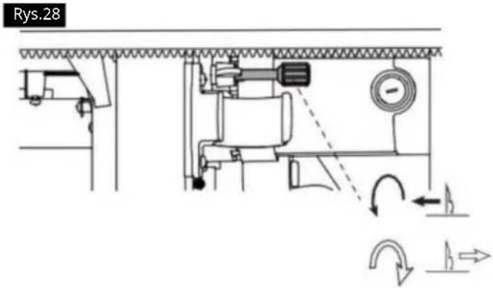
Dostosowania
WYRÓWNANIE OGRANICZNIKA WZDŁUŻNEGO
OSTRZEŻENIE
natural_image
Technical line drawing of a mechanical cutting machine with no visible text or symbolsDostosowania
natural_image
Two mechanical gear diagrams labeled A and B showing gear meshing and cutting process (no text or symbols present)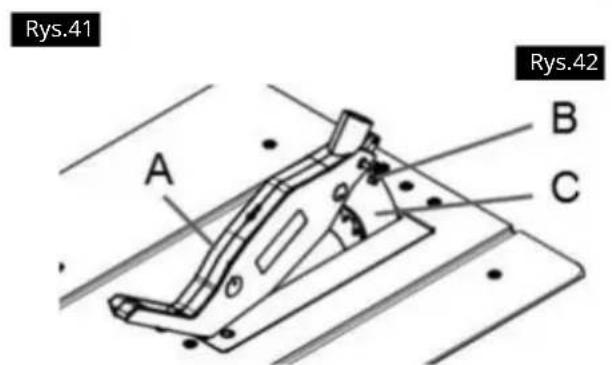
natural_image
Technical line drawing of a mechanical device with an inset showing a close-up of its internal components (no text or symbols present)UŻYWANIE WSKAŻNIKA PROWADNICY RIP
natural_image
Technical line drawing of a mechanical device with an inset showing a bracket assembly (no text or symbols).FIG.48
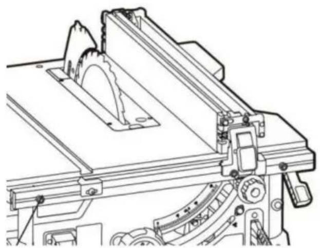
natural_image
Technical line drawing of a mechanical assembly with no visible text or symbolsnatural_image
Technical line drawing of a mechanical clamp or bracket assembly (no text or symbols)
natural_image
Line drawing of a mechanical setup with hands operating a workbench and a curved component (no text or symbols)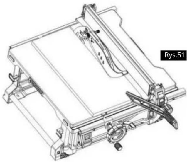
natural_image
Technical line drawing of a mechanical assembly with no visible text or symbolsRys.52

natural_image
Line drawing of hands using a tool to cut or spread a piece of material on a cutting board (no text or symbols)FIG. 55
natural_image
Line drawing of a hand using a tool to cut or spread material on a cutting board (no text or symbols)CIECIE POD KATEM
natural_image
Line drawing of hands using a tool to cut or spread a piece of paper (no text or symbols)CIĘCIE POPRZECZNE SKOŚNE
natural_image
Line drawing of hands using a manual saw to cut a piece of wood (no text or symbols)CIĘCIE POD KĄTEM ZŁOŻONYM
CIĘCIE METALI I MURARSTWO

natural_image
Technical line drawing of a mechanical assembly with no visible text or symbols


natural_image
Technical line drawing of a mechanical component with labeled parts (no readable text or symbols)

VEVOR®
TOUGH TOOLS, HALF PRICE
natural_image
Technical line drawing of a mechanical machine with cutaway view (no text or symbols)HULP NODIG? NEEM CONTACT MET ONS OP!
BEWAAR ALLE WAARSCHUWINGEN EN INSTRUCTIES VOOR TOEKOMSTIGE REFERENTIE.
WAARSCHUWINGEN MET BETREKKING TOT BEWAKING
PROCEDuRE WAARSCHUWINGEN
natural_image
Icon of a person wearing glasses inside a circle (no text or symbols)

shock during unpacking and setting up, do
table saw, plug in the power cord or turn the switch on until the missing parts are obtained
natural_image
Pure diagram of a container with wheels and a labeled section A, no text or symbols present
Montage
BEVESTIGEN VAN DE BESCHERMINGSEENHEID
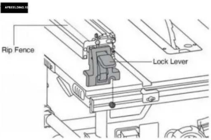
Opslag, transport en montage
MONTAGE VAN DE TAFELZAAG
natural_image
Line drawing of a hand using a pliers to cut a metal sheet (no text or symbols)Aanpassingen
AFSTELLEN VAN HET MES PARALLELLE AAN DE VERSTEKMAATSLEUVEN
FIG27
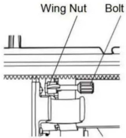
Uitlijnbouten
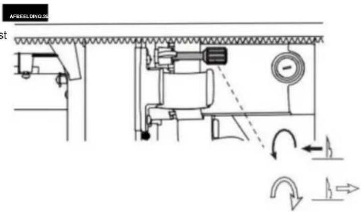
Aanpassingen
UITLIJNEN VAN DE RIP FENCE

WAARSCHUWING
natural_image
Technical line drawing of a mechanical cutting machine with no visible text or symbolsAanpassingen
natural_image
Two mechanical gear diagrams labeled A and B, showing gear meshing and mounting components (no text or symbols present)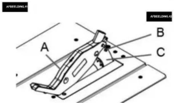
BEVESTIGEN VAN DE BESCHERMINGSEENHEID
natural_image
Technical line drawing of a mechanical device with an inset showing a close-up of its internal components (no text or symbols present)FIG.470
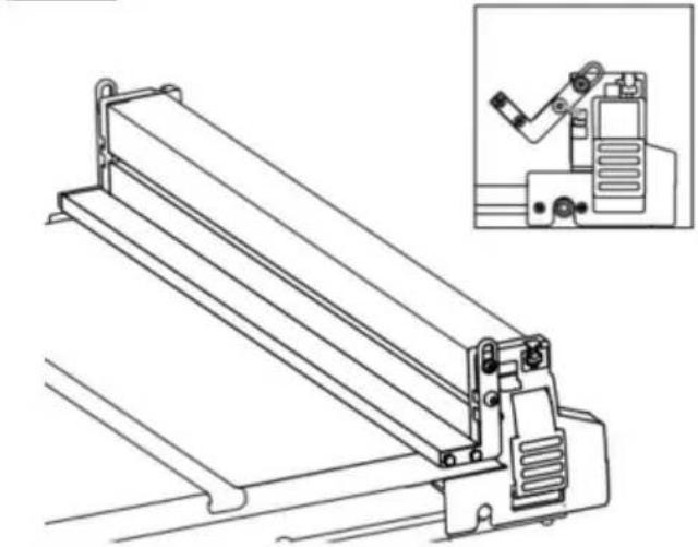
natural_image
Technical line drawing of a mechanical device with an inset showing a close-up of its component (no text or symbols present)GEBRUIK VAN DE RIP FENCE-AANWIJZER
natural_image
Technical line drawing of a mechanical assembly with cutaway view (no text or symbols)RIP FENCE HULPBESCHERMING
natural_image
Technical line drawing of a mechanical clamp or bracket assembly (no text or symbols)
natural_image
Line drawing of a mechanical assembly with hands operating a workbench (no text or symbols)
natural_image
Technical line drawing of a mechanical assembly with no visible text or symbolsAFBEELDING.52

natural_image
Line drawing of hands using a tool to cut or spread a piece of material on a cutting board (no text or symbols)FIG.55
natural_image
Line drawing of a hand using a tool to cut or spread a piece of paper, with no visible text or symbols.VERSTEK ZAGEN
SCHUINE SNIJDING
natural_image
Line drawing of hands using a manual saw to cut a piece of wood (no text or symbols)SAMENGESTELDE VERSTEK ZAGEN
natural_image
Technical line drawing of a mechanical assembly with no visible text or symbols

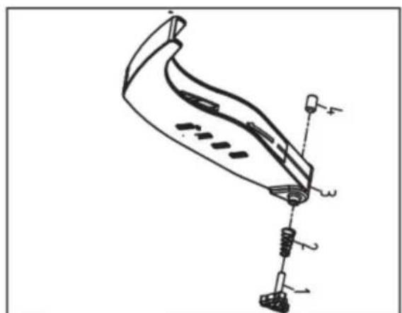
natural_image
Technical line drawing of a mechanical component with labeled parts (no readable text or symbols)

VEVOR®
TOUGH TOOLS, HALF PRICE
Technische ondersteuning en E-garantiecertificaat www.vevor.comlsupport
VEVOR®
TOUGH TOOLS, HALF PRICE
natural_image
Technical line drawing of a mechanical machine with cutaway view (no text or symbols)BEHÖVER HJÄLP? KONTAKTA OSS!
natural_image
Icon of a person wearing glasses inside a circle (no text or symbols)

natural_image
Simple line drawing of a container with wheels and a labeled point A (no text or symbols beyond label)FIG.5
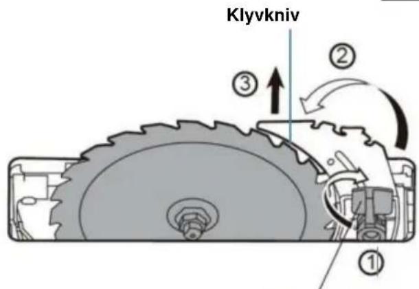
Release Lever
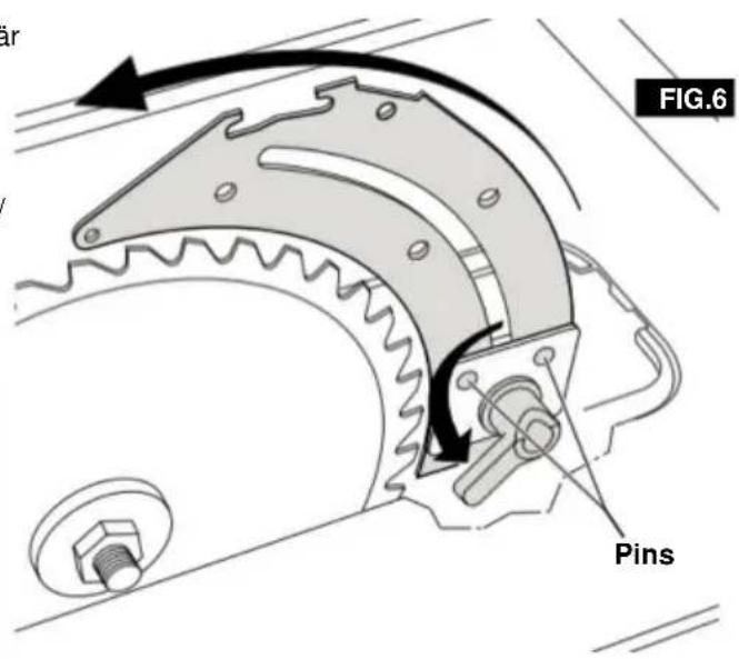
Montering
FÄSTNING AV SKYDDMONTERING Montera
FIG.15
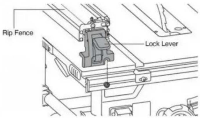
natural_image
Line drawing of a hand using a tool to cut or mark a piece of wood, no text or symbols presentFIG.25
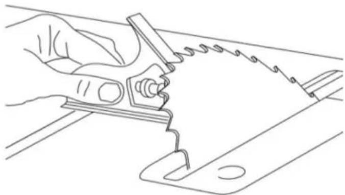
natural_image
Line drawing of a hand using a pliers to cut a sheet of paper (no text or symbols present)Justeringar
JUSTERING AV BLAD PARALLELLT TILL GIRINGSMÄTARSPLARNA
Justeringsbultar
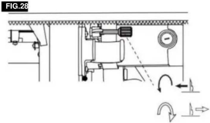
Justeringar
JUSTERING AV RIVSTÄNGSEL
WARNING
natural_image
Technical line drawing of a mechanical cutting machine with no visible text or symbolsJusteringar
PointerAdjustments skruvar
Vänster sida
Höger sida 1
Höger sida
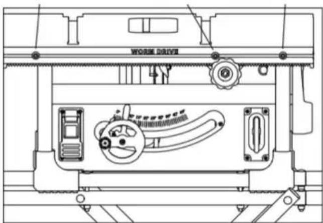
SÅ HÄR STÄLLER DU IN RIVSTÄNGSELSPEKEREN:
FIG. 31
Justeringar
natural_image
Two mechanical diagrams labeled A and B showing gear meshing or cutting process (no text or symbols present)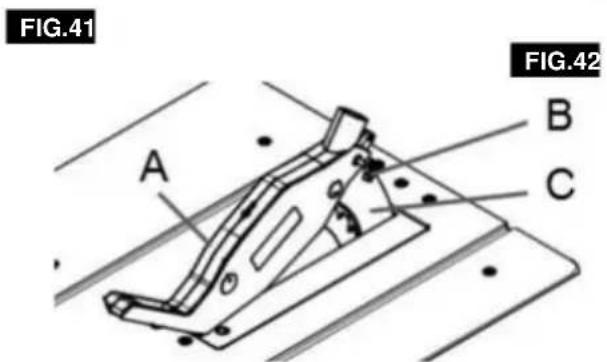
FÄSTNING AV SKYDDMONTAGET
natural_image
Technical line drawing of a mechanical device with an inset showing a bracket assembly (no text or symbols)
natural_image
Technical line drawing of a mechanical device with an inset showing a close-up of a bracket assembly (no text or symbols)ANVÄNDNING AV RIVSTÄNGSELSMARKEREN
natural_image
Technical line drawing of a mechanical assembly with cutaway view (no text or symbols)natural_image
Technical line drawing of a mechanical clamp or bracket assembly (no text or symbols)natural_image
Line drawing of a mechanical assembly with hands operating a workpiece (no text or symbols)FAS RIPPNING
natural_image
Technical line drawing of a mechanical assembly with no visible text or symbolsFIG. 52

natural_image
Line drawing of hands using a tool to cut or spread a piece of material on a flat surface (no text or symbols)FIG. 55
natural_image
Line drawing of a hand using a tool to cut or spread a piece of paper (no text or symbols present)GERINGSKÄRNING
natural_image
Line drawing of hands using a tool to cut or spread a piece of paper (no text or symbols present)AVFANSNING
natural_image
Line drawing of hands using a manual saw to cut a piece of wood (no text or symbols)SAMMANSTÄLLD GERINGSKÄRNING
- ALLA reparationer.
natural_image
Technical line drawing of a mechanical assembly with no visible text or symbols


natural_image
Technical line drawing of a mechanical component with labeled parts (no readable text or symbols)

VEVOR®
TOUGH TOOLS, HALF PRICE