DC235 - Saw Vevor - Free user manual and instructions
Find the device manual for free DC235 Vevor in PDF.

| Brand | Vevor |
| Model | DC235 |
| Product Type | Concrete Saw |
| Power Supply | 120 V / 60 Hz or 220-240 V / 50 Hz |
| Input Power | 1800 W (120 V) / 2200 W (220-240 V) |
| Blade Diameter | F9 (9 inches / 229 mm) |
| Maximum Cutting Depth | 3.5 inches (89 mm) |
| No-Load Speed | 5800 rpm (120 V) / 4800 rpm (220-240 V) |
| Weight | 9.4 kg |
| Main Features | Powerful motor, adjustable guard, soft start, auxiliary handle |
| Functions | Cutting concrete, masonry, tile |
| Maintenance and Cleaning | Regularly clean ventilation slots, check carbon brush wear |
| Safety | Adjustable blade guard, safety switch, recommendation to wear safety glasses |
| Spare Parts | Carbon brushes, saw blades, flanges, bearings, seals |
| Repairability | Detailed parts list in manual; repair by qualified technician |
| General Information | Brand VEVOR, model DC235, professional tool, includes user manual |
Frequently Asked Questions - DC235 Vevor
User questions about DC235 Vevor
0 question about this device. Answer the ones you know or ask your own.
Ask a new question about this device
Download the instructions for your Saw in PDF format for free! Find your manual DC235 - Vevor and take your electronic device back in hand. On this page are published all the documents necessary for the use of your device. DC235 by Vevor.
USER MANUAL DC235 Vevor
Technical Support and E-Warranty Certificate
www.vevor.com/support
CONCRETE SAW OWNER'S MANUAL
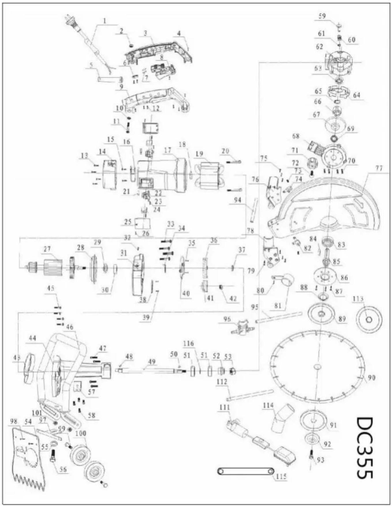
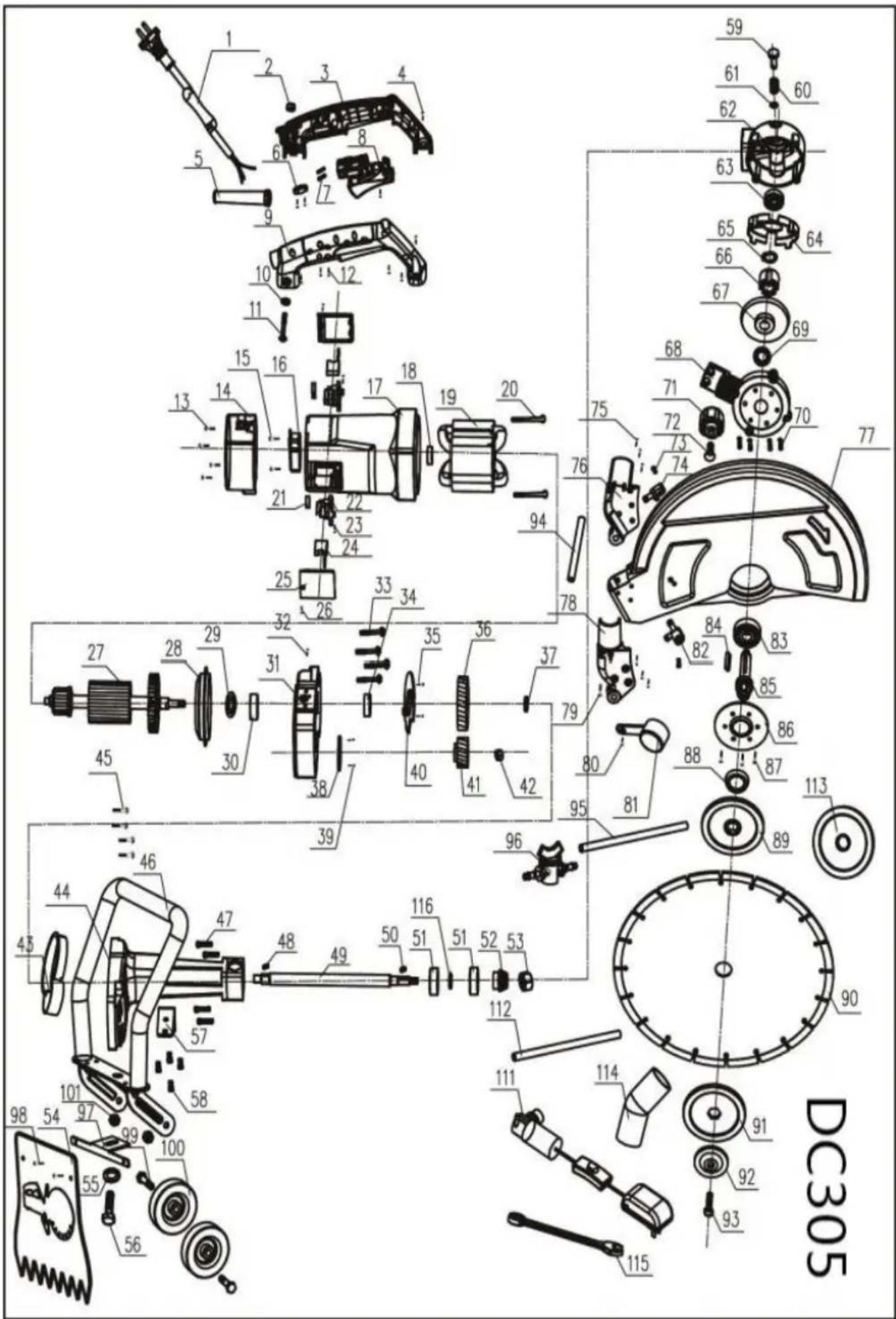
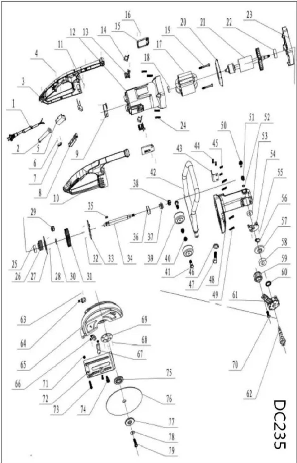
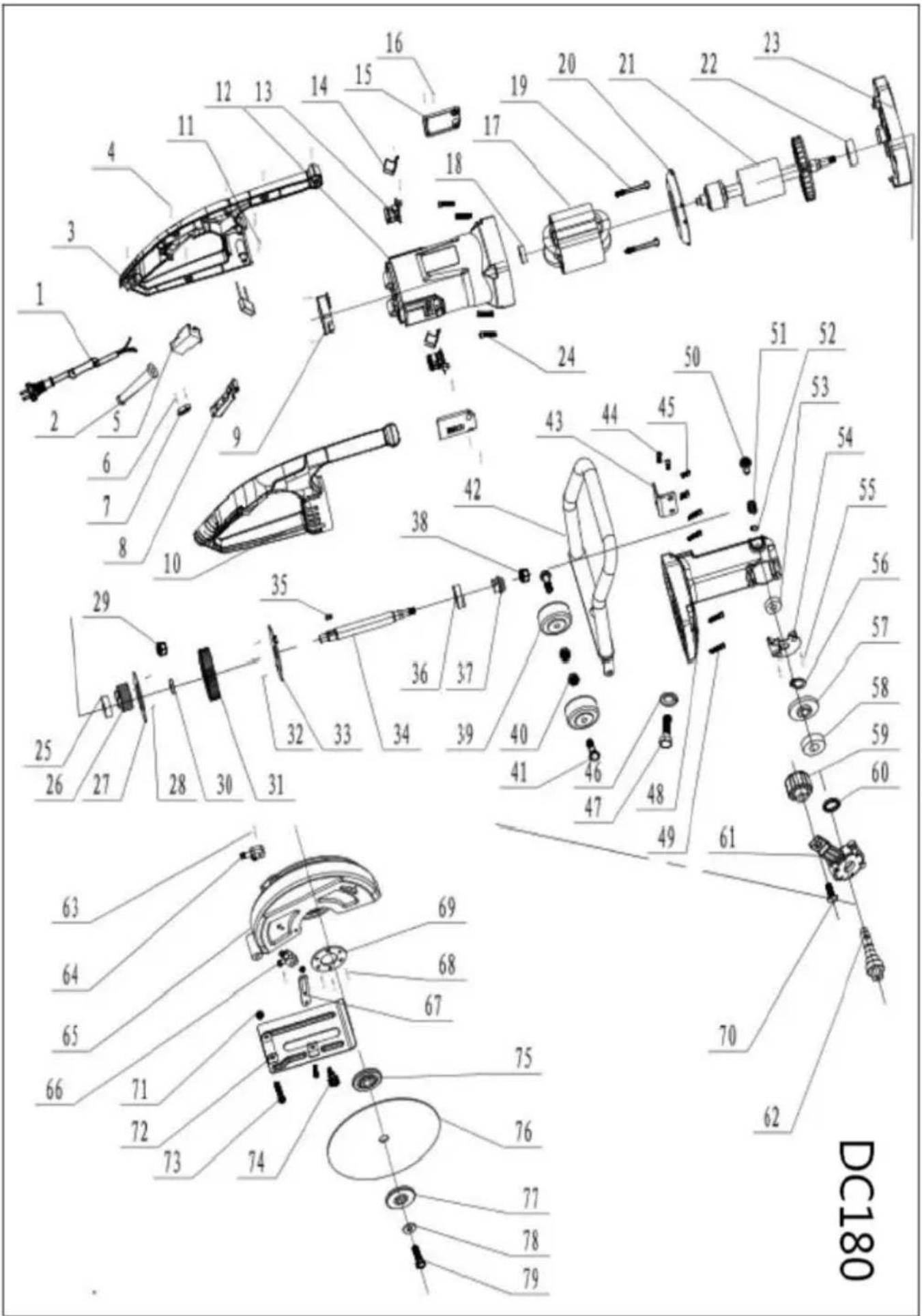
MODEL: DC180/235/305/355/425
We continue to be committed to provide you tools with competitive price. "Save Half", "Half Price" or any other similar expressions used by us only represents An estimate of savings you might benefit from buying certain tools with us compared to the major top brands and does not necessarily mean to co all categories of tools offered by us. You are kindly reminded to verify carefully when you are Placing an order with us if actually are saving half in comparison with the top major brands.
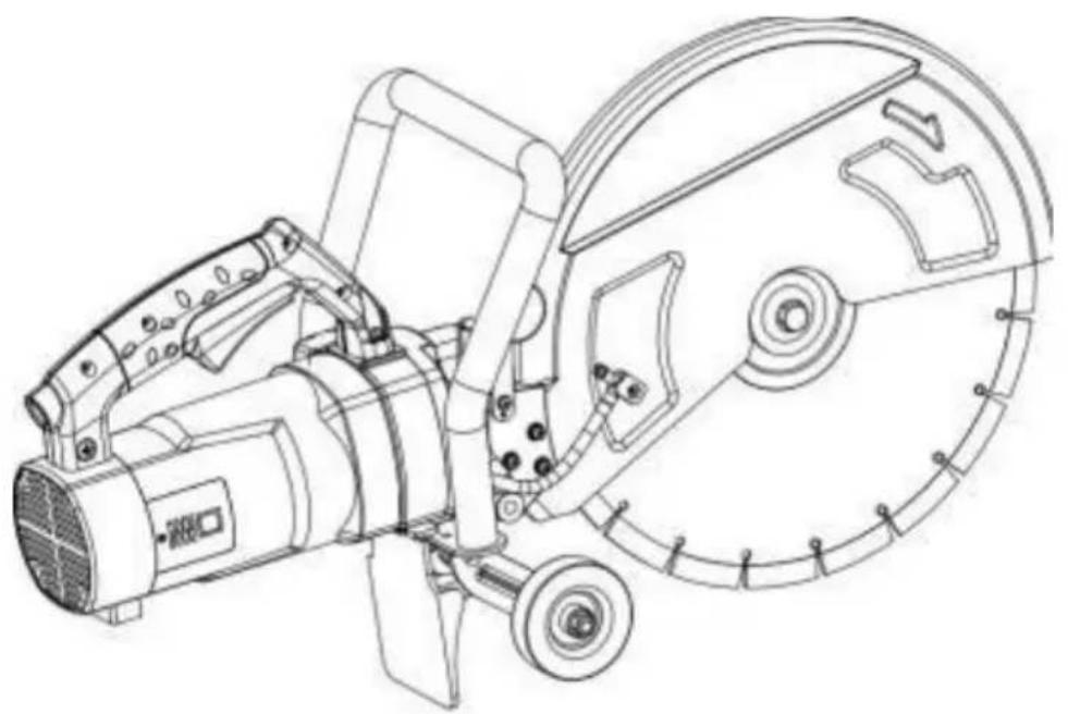
natural_image
Technical line drawing of a mechanical device with no visible text or symbols< Picture Only For Reference >
NEED HELP? CONTACT US!
Have product questions? Need technical support? Please feel free contact us:
Technical Support and E-Warranty Certificate www.vevor.com/support
This is the original instruction, please read all manual instruction carefully before operating. VEVOR reserves a clear interpretation user manual. The appearance of the product shall be subject to product you received. Please forgive us that we won't inform your data on our product.
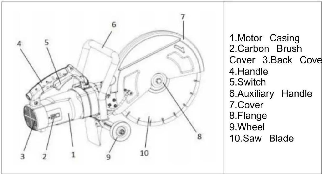
MAIN CONSTRUCTION
MAIN SPECIFICATIONS
| Model | Power Supply (V/Hz) | Input (W) | Maximum Cutting Depth(in) | Saw Blade Diameter (in) | No-load Speed (RPM) | N.W. (kg) |
| DC425 | 120/60 | 3200 | 6 | Φ16 | 3600 | 17 |
| 220-240/50 | 3200 | 6 | Φ16 | 3600 | 17.8 | |
| DC355 | 120/60 | 3200 | 5 | Φ14 | 4600 | 15.8 |
| 220-240/50 | 3200 | 5 | Φ14 | 4300 | 15.8 | |
| DC305 | 120/60 | 1800 | 4.5 | Φ12 | 5300 | 13.5 |
| 220-240/50 | 3200 | 4.5 | Φ2 | 5200 | 13.2 | |
| DC235 | 120/60 | 1800 | 3.5 | Φ9 | 5800 | 9.4 |
| 220-240/50 | 2200 | 3.5 | Φ9 | 4800 | 9.4 | |
| DC180 | 120/60 | 2000 | 2.5 | Φ7 | 5400 | 8.6 |
| 220-240/50 | 2000 | 2.5 | Φ7 | 5100 | 8.9 |
WARNING: To reduce the risk of injury, user must read instruction m «MISE EN
- M002 of ISO 7010
- Date of manufacture.
-Rated speed in revolutions per minute;
-Rated capacity in mm;
-Tools provided with a threaded spindle shall be marked with spindle thread size;
-WARNING Always wear eye protection, “AVERTISSEMENT Toujours porter des lunettes de sécurité” or equivalent or the sign M004 of IS 7010 or the following safety sign:

The eye protection symbol may be modified by adding other personal protective equipment such as ear protection, dust mask, etc.
WARNING
To reduce the risk of injury, use a proper guard and use only acces- rated at least equal to the maximum speed marked on the tool.
In Canada, the equivalent French wording is as follows:
For cut-off machines with a permanently fixed guard, the following alternative warning may be used:
WARNING
To reduce the risk of injury, use only accessories rated at least equal the maximum speed marked on the tool.
In Canada, the equivalent French wording is as follows:
Note: Minimum 2.4mm high letters for "WARNING".
See standard CAN/CSA-C22.2 No. 60745-1-07 + UPD 1, 2, 3, (UL 6) 1-4th (Nov.28,
2016) and CAN/CSA-C22.2 No. 60745-2-22-12+UPD 1 (reaffirmed 2017, (UL 60745-2-22-1st (June 19, 2014)) for details.
An instruction manual and safety instructions shall be provided with the tool and
packaged in such a way that the user notices when the tool is removed from the packaging. The safety instructions may be separate from the instruction manual. An
explanation of the symbols required by this standard shall be provided either the instruction manual or the safety instructions.
They shall be written in the country's official language(s) where the to sold They shall be legible and contrast with the background.
They shall include the name and address of the manufacturer, supply any other agent responsible for placing the tool on the market.
The General Power Tool Safety Warnings and the specific tool Safety Warnings, if in English, shall be verbatim and in any other official law to be equivalent.
Format of all Safety Warnings must differentiate, by font highlighting or similar means, the context of clauses as illustrated below.
General Safety Rules
WARNING!
Read all safety warnings and all instructions. Failure to follow the wa and instructions may result in electric shock, fire and/or serious injury. Save all warnings and instructions for future reference. The term "pow tool" in all of the warnings listed below refers to your
mains-operated (corded) power tool or battery-operated (cordless) power tool.
1) Work Area Safety
a) Keep work area clean and well-lit. Cluttered or dark areas invite accidents.
b) Do not operate power tools in explosive atmospheres, such as in flammable liquids, gases or dust. Power tools create sparks that may ignite the dust of fumes.
c) Keep children and bystanders away while operating a power tool. Distractions can cause you to lose control.
2) Electrical Safety
a) Power tool plugs must match the outlet. Never modify the plug in way. For example, do not use adapter plugs with earthed (grounded) power tools.
Unmodified plugs and matching outlets will reduce the risk of electric shock.
b) Avoid body contact with earthed or grounded surfaces, such as pip radiators, ranges and refrigerators. There is an increased risk of electric shock if your body is earthed or grounded.
c) Do not expose power tools to rain or wet conditions. Water enter power tool will increase the risk of electric shock.
d) Do not abuse the cord. Never use the cord for carrying, pulling or unplugging the power tool. Keep cord away from heat, oil, sharp edge moving parts. Damaged or entangled cords increase the risk of electric shock.
e) When operating a power tool outdoors, use an extension cord suit for outdoor use. A cord ideal for outdoor use reduces the risk of ele shock.
f) If operating a power tool in a damp location is unavoidable, use a ground fault circuit interrupter (GFCI) protected supply. Use of an GFCI reduces the risk of electric shock.
3) Personal Safety
a) Stay alert, watch what you are doing and use common sense who operating a power tool. Do not use a power tool while you are tired under the influence of drugs, alcohol or medication. A moment of inattention while operating power tools may result in serious personal injury.
b) Use personal protective equipment. Always wear eye protection. Protective equipment such as dust mask, non-skid safety shoes, hard or hearing protection used for appropriate conditions will reduce personal injuries.
c) Prevent unintentional starting. Ensure the switch is in the off-position before connecting to power source and/or battery pack, picking up or
carrying the tool. Carrying power tools with your finger on the switch energising power tools that have the switch on invites accidents.
d) Remove any adjusting key or wrench before turning the power too. A wrench or a key left attached to a rotating part of the power tool result in personal injury.
e) Do not overreach. Keep proper footing and balance at all times. 7 enables better control of the power tool in unexpected situations.
f) Dress properly. Do not wear loose clothing or jewellery. Keep your clothing and gloves away from moving parts. Loose clothes, jewellery long hair can be caught in moving parts.
g) If devices are provided for the connection of dust extraction and collection facilities, ensure these are connected and properly used. Use dust collection can reduce dust-related hazards.
4) Power Tool Use And Care
a.Do not overload the machine. When the machine is overloaded, the overload indicator will light up.
b. Do not force the power tool. Instead, use the correct power tool fo application. The proper power tool will do the job better and safer at rate for which it was designed.
c.Do not use the power tool if the switch does not turn on and off. power tool that cannot be controlled with the switch is dangerous and must be repaired.
d.Disconnect the plug from the power source and/or the battery pack the power tool before making any adjustments, changing accessories, storing power tools. Such preventive safety measures reduce the risk starting the power tool accidentally.
e. Store idle power tools out of the reach of children and only allow persons familiar with the power tool or these instructions to operate t power tool.
f.Power tools are dangerous in the hands of untrained users.
g. Maintain power tools. Check for misalignment or binding of moving breakage of parts and any other condition that may affect the power operation. If damaged, have the power tool repaired before use. Poor maintained power tools cause many accidents.
h. Keep cutting tools sharp and clean. Properly maintained cutting tools with sharp edges are less likely to bind and are easier to control.
i. Use the power tool, accessories, tool bits, etc., following these instructions, considering the working conditions and the work to be
performed. Using the power tool for operations different from those intended could result in a hazardous situation.
5) Service
a) Have your power tool serviced by a qualified repair person using identical replacement parts. This will ensure that the safety of the power tool is maintained.
Special requirement for cutting off tool.
6) Cut-off machine safety warnings.
a) The guard provided with the tool must be securely attached to the power tool and positioned for maximum safety so that the least amount wheel is exposed to the operator. Position yourself and your bystander away from the plane of the rotating wheel. The guard helps protect the operator from broken wheel fragments and accidental contact with the wheel.
b) Use only bonded reinforced or diamond cut-off wheels for your power tool. Just because an accessory can be attached to your power tool, does not assure safe operation.
c) The accessory's rated speed must be equal to the maximum speed marked on the power tool. Accessories running faster than their rated speed can break and fly apart.
d) Wheels must be used only for recommended applications. For example, do not grind with the side of the cut-off wheel. Although abrasive cut wheels are intended for peripheral grinding, side forces applied to these wheels may cause them to shatter.
e) Always use undamaged wheel flanges of the correct diameter for selected wheel. Proper wheel flanges support the wheel, thus reducing possibility of wheel breakage
f) Do not use worn down reinforced wheels from more powerful power tools. Wheels intended for a larger power tool are not suitable for the higher speed of a smaller tool and may burst.
NOTE
The above warning does not apply to tools only designated to be us with diamond wheels.
g) The outside diameter and the thickness of your accessory must be within the capacity rating of your power tool. Only appropriately sized accessories can be adequately guarded or controlled.
h) The arbor size of wheels and flanges must properly fit the spindle power tool.
Wheels and flanges with arbor holes that do not match the mounting hardware of the power tool will run out of balance, vibrate excessively may cause loss of control.
i) Do not use damaged wheels. Before each use, inspect the wheels chips and cracks. Check for damage or install an undamaged wheel if power tool or wheel is dropped.
After inspecting and installing the wheel, position yourself and bystander away from the plane of the rotating wheel and run the power tool a maximum no load speed for one minute. Damaged wheels will normal break apart during this test time.
j) Wear personal protective equipment. Use a face shield, safety gogg or safety glasses, depending on the application. In addition, wear a d mask, hearing protectors, gloves, and shop apron capable of stopping small abrasive or workpiece fragments. The eye protection must be capable of stopping flying debris generated by various operations. The dust mask or respirator must be capable of filtrating particles generate by your process. Prolonged exposure to high-intensity noise may cause hearing loss.
k) Keep bystanders at a safe distance away from the work area. An entering the work area must wear personal protective equipment. For example, fragments of workpieces or a broken wheel may fly away a cause injury beyond the immediate scope of operation.
I) Hold the power tool by insulated gripping surfaces only when perform an operation where the cutting accessory may contact hidden wiring cord. Cutting accessories getting a "live" wire may make exposed met parts of the power tool "live" and could give the operator an electric m) Position the cord clear of the spinning accessory. If you lose con the cord may be cut or snagged, and your hand or arm may be put the spinning wheel.
n) Only lay the power tool down once the accessory has completely stopped. The spinning wheel may grab the surface and pull the power out of your control.
o) Do not run the power tool while carrying it. Accidental contact with spinning accessory could snag your clothing, pulling the addition into body. p) Regularly clean the power tool's air vents. The motor's fan will draw the dust inside the housing, and excessive accumulation of powdered metal may cause electrical hazards.
q) Do not operate the power tool near flammable materials. Sparks c ignite these materials.
r) Do not use accessories that require liquid coolants. Using water or liquid coolants may result in electrocution or shock.
Further safety instructions for abrasive cutting-off operations.
Kickback and related warnings
Kickback is a sudden reaction to a pinched or snagged rotating wheel. Pinching or snagging causes rapid stalling of the rotating wheel, which causes the uncontrolled power tool to be forced in the direction oppo the wheel's rotation at the binding point. For example, if an abrasive is snagged or pinched by the workpiece, the edge of the revolution entering into the pinch point can dig into the material's surface, causi the wheel to climb out or kick out. In addition, the wheel may either toward or away from the operator, depending on the direction of the wheel's movement at the point of pinching. Abrasive wheels may also break under these conditions
Kickback results from power tool misuse and incorrect operating procedures or conditions and can be avoided by taking proper precau as given below.
a) Maintain a firm grip on the power tool and position your body an to allow you to resist kickback forces. Always use auxiliary handle, if provided, for maximum control over kickback or torque reaction during start-up. The operator can control torque reactions or kickback forces, proper precautions are taken.
b) Never place your hand near the rotating accessory. Accessory may kickback over your hand.
c) Do not position your body in line with the rotating wheel. Kickback propel the tool in direction opposite to the wheel's movement at the of snagging.
d) Use special care when working corners, sharp edges etc. Avoid bouncing and snagging the accessory. Corners, sharp edges or bounci have a tendency to snag the rotating accessory and cause loss of c or kickback.
e) Do not attach a saw chain, woodcarving blade, segmented diamond wheel with a peripheral gap greater than 10 mm or toothed saw blade. Such blades create frequent kickback and loss of control.
f) Do not "jam" the wheel or apply excessive pressure. Do not attempt make an excessive depth of cut. Overstressing the wheel increases the loading and susceptibility to twisting or binding of the wheel in the circle the possibility of kickback or wheel breakage.
g) When the wheel is binding or when interrupting a cut for any rear switch off the power tool and hold the power tool motionless until the wheel comes to a complete stop. Never
attempt to remove the wheel from the cut while the wheel is in mot otherwise kickback may occur. Investigate and take corrective action to eliminate the cause of wheel binding.
h) Do not restart the cutting operation in the workpiece. Let the whe reach full speed and carefully re-enter the cut. The wheel may bind, up or kickback if the power tool is restarted in the workpiece.
i) Support panels or any oversized workpiece to minimize the risk of pinching and kickback. Large workpieces tend to sag under their own weight. Therefore, supports must be placed under the workpiece near tl cut line and the edge of the workpiece on both sides of the wheel.
j) Use extra caution when making a “pocket cut” into existing walls of blind areas.
The protruding wheel may cut gas or water pipes, electrical wiring or objects that can cause kickback.
OPERATING INSTRUCTIONS
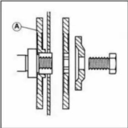 | OPERATING INSTRUCTIONSINSTALLING/REMOVING A DISCWARNING:Always disconnect the machine the power supply before installing or remove Cutting Disc.Ensure that the machines arbor and the flanges are clean and free from dust and Ensure that the direction of rotation mark the blade matches the direction of rotation marked on machines guard. |
 | Note:The arbor bolt has a left-hand thread. Turn counterclockwise to tighten the arbor. Turn clockwise to loosen the arbor to remove a cutting disc, reverse the above installation procedure |
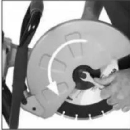
 | CUTTING ADVICEPRE-CUTTING ADVICE• Ensure that the power supply matches the requirements specified on the machine's rating plate.• Ensure that the machine trigger switch is the “OFF” position. If the machine is connea power source with trigger switch the “ON”position , the machine could start operating immediately with the possibility of serious accident occurring.• If an extension cable is required it must suitable type for use outdoors and so label• The manufacturers instructions should be followed when using an extension cable.• Route any extension cable so that it doe pose a trip (or any other ) hazard to the operator to any bystanders.WHEEL GUARD ADJUSTMENTThe wheel guard is adjustable and should positioned to provide the operator with thecombination of personal protection and visibility of cutting area. Loosen the wheel gard locking knob and rotate the guard to the required position.(FIG.6) Securely tighten the wheel guard locking to lock the guard in place. Note: the tightness of this locking knob and security of the wheel guard should be checked regularly when operations commence. |
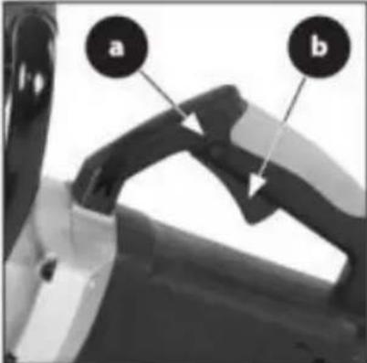 FIG. 5a & 5b FIG. 5a & 5b | THE ON/OFF TRIGGER SWITCHThis machine is equipped with a safety sta trigger switch.To start the tool: Push in the safety lock button (Fig.5a) o side of the handle with your thumb.Depress the main trigger switch (Fig.5b) t the motor.WARNING: Never start the saw with the c edge of the saw blade in contact with the workpiece surface. |
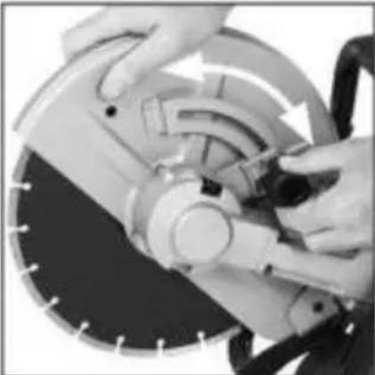 FIG. 6 FIG. 6 | CUTTING ADVICEPRE-CUTTING ADVICEEnsure that the power supply matches the requirements specified on the matches the requirements specified on the machines ratir plate.Ensure that the machine trigger switch is “OFF” position. If the machine is connected power source with trigger switch the “ON”pc, the machine could start operating immedia with the possibility of a serious accident occurring.If an extension cable is required it must suitable type for use outdoors and so labelThe manufacturers instructions should be followed when using an extension cable.Route any extension cable so that it doe pose a trip (or any other ) hazard to the to any bystanders.WHEEL GUARD ADJUSTMENTThe wheel guard is adjustable and should positioned to provide the operator with the combination of personal protection and visib of cutting area.Loosen the wheel gard locking knob and the guard to the required position. (FIG.6)Securely tighten the wheel guard locking to lock the guard in place.Note: the tightness of this locking knob an security of the wheel guard should be checked regularly when operations commence. |
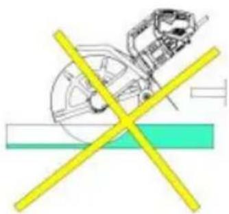 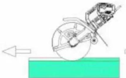 | Carefully guide the blade into the workpie Best performance is achieved when cutting straight along a pre-marked cutting line. Do not cut deeper than 50mm (2 inches).If a cut deeper than 50 mm (2 inches) needed, make multiple passes.Cut smoothly, letting the machine do the without applying excessive force to the blade WARNING: Do not try to cut curved or zig lines.Never use the side of the blade as a cut surface. Do not use it for angled cutting. |

| No. | Part Description | Qty | No. | Part Description | Qty |
| 1 | Electric Wire | 1 | 37 | 6301Z Rolling Bearing | 2 |
| 2 | Sheath | 1 | 38 | Connecting Shaft Gask | 1 |
| 3 | Wire Pressing Plate | 1 | 39 | Bevel Gear | 1 |
| 4 | Tapping ScrewST4.2*16 | 7 | 40 | M8 Lock Nut | 1 |
| 5 | Right Handle | 1 | 41 | Combination Screw M5*25 | 4 |
| 6 | Switch | 1 | 42 | 6# Open Retainer | 1 |
| 7 | Casing | 1 | 43 | Self-locking Pin Spring | 1 |
| 8 | Soft Start | 1 | 44 | Self-locking Pin | 1 |
| 9 | Left Handle | 1 | 45 | Gear Box | 1 |
| 10 | Left Carbon Brush Cover | 1 | 46 | Gearbox Oil Baffle Pla | 1 |
| 10.1 | Right Carbon Brush Cover | 1 | 47 | Combination Screw M6*45 | 4 |
| 11 | Combination Screw M5*16 | 2 | 48 | 6200RS Rolling Bearing | 1 |
| 12 | Tapping Screw ST4.2*10 | 5 | 49 | Self-locking Sleeve | 1 |
| 13 | Carbon Brush Holder | 2 | 50 | Big Bevel Gear | 1 |
| 14 | Coil Spring | 2 | 51 | Plain Flat Bond | 1 |
| 15 | Carbon Brush | 2 | 52 | 6302RS Rolling Bearing | 2 |
| 16 | Tapping Screw ST4.2*10 | 4 | 53 | Skeleton Seal Ring | 1 |
| 17 | Combination Screw M4*10 | 2 | 54 | Gear Box Cover | 1 |
| 18 | Hex Socket Screw M5X35 | 4 | 55 | Hexagon Socket Screw M5X22 | 4 |
| 19 | 629RS Bearing | 1 | 56 | Lock The Hand Whee | 1 |
| 20 | Stator | 1 | 57 | Φ 8 Gasket | 1 |
| 21 | Screw M5*80 | 2 | 58 | Screw M8*24 | 1 |
| 22 | Windshield Ring | 1 | 59 | Output Shaft | 1 |
| 23 | Rotor | 1 | 60 | Soldering Cup | 1 |
| 24 | Middle Cover | 1 | 61 | Protective Cover | 1 |
| 25 | 6202 RS Bearings | 1 | 62 | Bearing Pressure Cove | 1 |
| 26 | Bearing Gland | 1 | 63 | Combination Screw M6 * | 3 |
| 27 | Screw M4*10 | 2 | 64 | M8 Pine Nut | 1 |
| 28 | Pinion Gear | 1 | 65 | Director Plate | 1 |
| 29 | M8 Locking Nuts | 1 | 66 | Screw M8 * 55 | 1 |
| 30 | 6200RS Rolling Bearing | 1 | 67 | M8 Pine Nut | 1 |
| 31 | Limit Washer | 1 | 68 | Link Rod | 1 |
| 32 | Big Cylindrical Gear | 1 | 69 | Screw M8*15 | 1 |
| 33 | Oil Baffle | 4 | 70 | Screw M8*24 | 1 |
| 34 | Long Handle | 1 | 71 | Φ 8 Gasket | 1 |
| 35 | Plain Flat Bond | 1 | 72 | Lock The Hand Wheel | 1 |
| 36 | Connecting Shaft | 1 | 73 | Saw Blade Inner Press Plate | 1 |
| No. | Part Description | Qty | No. | Part Description | Qty |
| 74 | Saw Bit | 1 | 89 | Screw M8*10 | 1 |
| 75 | Saw Outer Pressing Plat | 1 | 90 | Screw M12*15 | 1 |
| 76 | Small Press Board | 6 | 91 | Water Pump | 1 |
| 77 | Screw M10*25 | 1 | 92 | Saw Wrenches | 1 |
| 78 | Inside Water Mouth | 1 | 93 | PVC Pipe 6*10 (length 0.6m) | 1 |
| 79 | Outer Water Mouth | 1 | 94 | Faucet | 1 |
| 80 | PVC Pipe 6*8 (长 230n | 1 | 95 | PVC Pipe 6*10 (length 5r | 1 |
| 81 | Screw M5*10 | 1 | 96 | Water baffle retaining plat | 1 |
| 82 | Screw M5*10 | 1 | |||
| 83 | Handle | 1 | |||
| 84 | Wheel ScrewM8*45 | 2 | |||
| 85 | Wheel | 2 | |||
| 86 | M8 Pine Nut | 2 | |||
| 87 | Dust Board | 1 | |||
| 88 | Screw M5*10 | 2 | |||
| No. | Part Description | Qty | No. | Part Description | Qty |
| 1 | Cable wire | 1 | 37 | Gear washer | 1 |
| 2 | Nut M6 | 1 | 38 | bearing pressure plate | 1 |
| 3 | Left handle | 1 | 39 | Screw M4x10 | 2 |
| 4 | Screw M5x20 | 2 | 40 | oil baffle | 1 |
| 5 | Cable sheath | 1 | 41 | Gear | 1 |
| 6 | Tension | 1 | 42 | Nut M8 | 1 |
| 7 | wiring buckle | 2 | 43 | oil baffle | 1 |
| 8 | switch | 1 | 44 | Gear box | 1 |
| 9 | right handle | 1 | 45 | Screw M5x25 | 4 |
| 10 | M6 washer | 1 | 46 | Handle | 1 |
| 11 | Screw M6x25 | 1 | 47 | Sctew M6x45 | 4 |
| 12 | Screw ST4x15 | 8 | 48 | Key 4x4x14 | 1 |
| 13 | Screw ST5x24 | 4 | 49 | Drive shaft | 1 |
| 14 | Motor End Cover | 1 | 50 | Key 3x3x14 | 1 |
| 15 | Screw ST4x15 | 2 | 51 | Bearing 6301RS | 2 |
| 16 | Soft Starter | 1 | 52 | gear | 1 |
| 17 | Motor Housing | 1 | 53 | Nut M8 | 1 |
| 18 | Bearing 609 RS | 1 | 54 | Breakwater | 1 |
| 19 | Stator | 1 | 55 | spring washer M12 | 1 |
| 20 | Screw ST5x80 | 2 | 56 | Screw M12x15 | 1 |
| 21 | Spring | 2 | 57 | Fixed plate | 1 |
| 22 | Brush Holder | 2 | 58 | Screw M6x16 | 4 |
| 23 | Screw ST4x10 | 2 | 59 | Lockpin | 1 |
| 24 | Brush | 2 | 60 | Lockpin-spring | 1 |
| 25 | Brush cover | 2 | 61 | Circlip for shaft 6 | 1 |
| 26 | Screw ST3x8 | 2 | 62 | Gear box | 1 |
| 27 | Rotor | 1 | 63 | Bearing 6200Z | 1 |
| 28 | baffle | 1 | 64 | oil baffle | 1 |
| 29 | Bearing washer | 1 | 65 | Circlip for shaft 15 | 1 |
| 30 | Bearing 6202 RS | 1 | 66 | Axle sleeve | 1 |
| 31 | Gear box | 1 | 67 | Bevel gear | 1 |
| 32 | Screw M4x10 | 1 | 68 | Gear cover | 1 |
| 33 | Screw ST5x40 | 4 | 69 | O-ringφ60x1.5 | 1 |
| 34 | Bearing 6200 RS | 1 | 70 | Screw M6x16 | 4 |
| 35 | Screw M4x10 | 2 | 71 | Locking handwheel | 1 |
| 36 | Gear | 1 | 72 | Squar Bolt M8x24 | 1 |
| No. | Part Description | Qty | No. | Part Description | Qty |
| 73 | Screw M5x10 | 2 | 98 | Screw M5x10 | 2 |
| 74 | Outlet | 1 | 99 | Bolt 35 | 2 |
| 75 | Screw M5x10 | 6 | 100 | wheel | 2 |
| 76 | Dust outlet (R) | 1 | 101 | Lock nut M8 | 2 |
| 77 | Guard | 1 | 102 | 1 | |
| 78 | Dust outlet (L) | 1 | 103 | 1 | |
| 79 | Screw M4x30 | 1 | 104 | 1 | |
| 80 | Screw M4x10 | 1 | 105 | 1 | |
| 81 | Dust outlet cover | 1 | 106 | 1 | |
| 82 | Outlet | 1 | 107 | 1 | |
| 83 | Bearing 6302Z | 1 | 108 | 1 | |
| 84 | Key 4x4x30 | 1 | 109 | 1 | |
| 85 | Spindle | 1 | 110 | 1 | |
| 86 | Bearing pressure plate | 1 | 111 | Water pump | 1 |
| 87 | Screw M6x16 | 3 | 112 | Pvc water pipe 6x8 | 1 |
| 88 | Dustproof ring | 1 | 113 | Flange | 1 |
| 89 | Flange | 1 | 114 | Dust casing | 1 |
| 90 | saw blade | 1 | 115 | 16#wrench | 1 |
| 91 | flange | 1 | 116 | washer | 1 |
| 92 | Washer | 1 | 117 | Hexagon Wrench | 1 |
| 93 | Screw | 1 | 118 | Bottom plate | 1 |
| No. | Part Description | Qty | No. | Part Description | Qty |
| 1 | Cable wire | 1 | 37 | Gear washer | 1 |
| 2 | Nut M6 | 1 | 38 | Bearing pressure plate | 1 |
| 3 | Left handle | 1 | 39 | Screw M4x10 | 2 |
| 4 | Screw M5x20 | 2 | 40 | Oil baffle | 1 |
| 5 | Cable sheath | 1 | 41 | Gear | 1 |
| 6 | Tension | 1 | 42 | Nut M8 | 1 |
| 7 | Wiring buckle | 2 | 43 | Oil baffle | 1 |
| 8 | Switch | 1 | 44 | Gear box | 1 |
| 9 | Right handle | 1 | 45 | Screw M5x25 | 4 |
| 10 | M6 washer | 1 | 46 | Handle | 1 |
| 11 | Screw M6x25 | 1 | 47 | Screw M6x45 | 4 |
| 12 | Screw ST4x15 | 8 | 48 | Key 4x4x14 | 1 |
| 13 | Screw ST5x24 | 4 | 49 | Drive shaft | 1 |
| 14 | Motor End Cover | 1 | 50 | Key 3x3x14 | 1 |
| 15 | Screw ST4x15 | 2 | 51 | Bearing 6301RS | 2 |
| 16 | Soft Starter | 1 | 52 | Gear | 1 |
| 17 | Motor Housing | 1 | 53 | Nut M8 | 1 |
| 18 | Bearing 609 RS | 1 | 54 | Breakwater | 1 |
| 19 | Stator | 1 | 55 | Spring washer M12 | 1 |
| 20 | Screw ST5x80 | 2 | 56 | Screw M12x15 | 1 |
| 21 | Spring | 2 | 57 | Fixed plate | 1 |
| 22 | Brush Holder | 2 | 58 | Screw M6x16 | 4 |
| 23 | Screw ST4x10 | 2 | 59 | Lockpin | 1 |
| 24 | Brush | 2 | 60 | Lockpin-spring | 1 |
| 25 | Brush cover | 2 | 61 | Circlip for shaft 6 | 1 |
| 26 | Screw ST3x8 | 2 | 62 | Gear box | 1 |
| 27 | Rotor | 1 | 63 | Bearing 6200Z | 1 |
| 28 | Baffle | 1 | 64 | Oil baffle | 1 |
| 29 | Bearing washer | 1 | 65 | Circlip for shaft 15 | 1 |
| 30 | Bearing 6202 RS | 1 | 66 | Axle sleeve | 1 |
| 31 | Gear box | 1 | 67 | Bevel gear | 1 |
| 32 | Screw M4x10 | 1 | 68 | Gear cover | 1 |
| 33 | Screw ST5x40 | 4 | 69 | O-ringφ60x1.5 | 1 |
| 34 | Bearing 6200 RS | 1 | 70 | Screw M6x16 | 4 |
| 35 | Screw M4x10 | 2 | 71 | Locking hand wheel | 1 |
| 36 | Gear | 1 | 72 | Squar Bolt M8x24 | 1 |
| No. | Part Description | Qty | No. | Part Description | Qty |
| 73 | Screw M5x10 | 2 | 98 | Screw M5x10 | 2 |
| 74 | Outlet | 1 | 99 | Bolt 35 | 2 |
| 75 | Screw M5x10 | 6 | 100 | Wheel | 2 |
| 76 | Dust outlet (R) | 1 | 101 | Lock nut M8 | 2 |
| 77 | Guard | 1 | 102 | 1 | |
| 78 | Dust outlet (L) | 1 | 103 | 1 | |
| 79 | Screw M4x30 | 1 | 104 | 1 | |
| 80 | Screw M4x10 | 1 | 105 | 1 | |
| 81 | Dust outlet cover | 1 | 106 | 1 | |
| 82 | Outlet | 1 | 107 | 1 | |
| 83 | Bearing 6302Z | 1 | 108 | 1 | |
| 84 | Key 4x4x30 | 1 | 109 | 1 | |
| 85 | Spindle | 1 | 110 | 1 | |
| 86 | Bearing pressure plate | 1 | 111 | Water pump | 1 |
| 87 | Screw M6x16 | 3 | 112 | PVC water pipe 6x8 | 1 |
| 88 | Dustproof ring | 1 | 113 | Flange | 1 |
| 89 | Flange | 1 | 114 | Dust casing | 1 |
| 90 | Saw blade | 1 | 115 | Wrench | 1 |
| 91 | Flange | 1 | 116 | Washer | |
| 92 | Washer | 1 | |||
| 93 | Screw | 1 | |||
| 94 | PVC water pipe 8x10 (230mm) | 1 | |||
| 95 | PVC water pipe 8x10 (5000mm) | 1 | |||
| 96 | Tap | 1 | |||
| 97 | Breakwater -plate | 1 |
| No. | Part Description | Qty | No. | Part Description | Qty |
| 1 | Power Cord | 1 | 37 | Bevel Gear | 1 |
| 2 | Sheath | 1 | 38 | Nut M8 | 1 |
| 3 | Left Hand Handle | 1 | 39 | Wheel | 2 |
| 4 | Tapping Screw ST4.2*16 | 6 | 40 | Locknut M10 | 2 |
| 5 | Switch | 1 | 41 | Screw M10*35 | 1 |
| 6 | Tapping Screw ST4.2*16 | 2 | 42 | Handle | 1 |
| 7 | Pressure Wire Plate | 1 | 43 | Hand Lifting Fixed Bo | 1 |
| 8 | Switch Trigger | 1 | 44 | Screw M5*15 | 2 |
| 9 | Soft Start | 1 | 45 | Screw M5*20 | 2 |
| 10 | Right Hand Handle | 1 | 46 | Elastic GasketΦ12 | 1 |
| 11 | Tapping Screw ST5*2 | 2 | 47 | Screw M12*15 | 1 |
| 12 | Machine Casing | 1 | 48 | Gearbox | 1 |
| 13 | Carbon Brush Fram | 2 | 49 | Screw M5*25 | 4 |
| 14 | Carbon Brush | 2 | 50 | Self-lock Pin | 1 |
| 15 | Carbon Brush Cove | 2 | 51 | Self-lock Spring | |
| 16 | Tapping Screw ST4.2*16 | 2 | 52 | Open Card Spring | 1 |
| 17 | Stator | 1 | 53 | Bearing 6000RS | 1 |
| 18 | Bearing 609RS | 1 | 54 | Oil Baffle Plate | 1 |
| 19 | Tapping Screw ST5*8 | 2 | 55 | Screw M4*10 | 2 |
| 20 | Fan Shroud | 1 | 56 | Card Spring Φ13 | 1 |
| 21 | Rotator | 1 | 57 | Large Umbrella Gear | 1 |
| 22 | Bearing 6202RS | 1 | 58 | Bearing 6202RS | 1 |
| 23 | Middle Cover | 1 | 59 | Lock Hand Wheel | 1 |
| 24 | Screw M5*35 | 60 | Seal Ring | 1 | |
| 25 | Bearing 6200RS | 4 | 61 | Gear Box Cover | 1 |
| 26 | Rotor Gear | 1 | 62 | Output Axis | 1 |
| 27 | Retaining Plate | 1 | 63 | Screw M5*10 | 1 |
| 28 | Screw M4*10 | 1 | 64 | Outlet Nozzle | 1 |
| 29 | locknut M8 | 2 | 65 | Shield | 1 |
| 30 | Large Wheel Limit Washer | 1 | 66 | Outlet Nozzle (outside) | 1 |
| 31 | Large Bevel Gear | 1 | 67 | Link Rod | 1 |
| 32 | Screw M4*10 | 1 | 68 | Screw M6*16 | 3 |
| 33 | Retaining Plate | 2 | 69 | Cover Pressure Cover | 1 |
| 34 | Coupling Shaft | 1 | 70 | Screw M8*24 | 1 |
| 35 | Flat key | 1 | 71 | locknut M8 | 1 |
| 36 | Bearing 6201RS | 1 | 72 | Bottom Plate Components | 1 |
| 73 | Screw M8*55 | 1 | |||
| 74 | Plum Screw | 1 | |||
| 75 | Internal Pressure Plate | 1 | |||
| 76 | Saw Blade | 1 | |||
| 77 | External Pressure Plate | 1 | |||
| 78 | Gasket Φ8*20 | 1 | |||
| 79 | Screw M8*16 | 1 |
| No. | Part Description | Qty | No. | Part Description | Qty |
| 1 | Power Cord | 1 | 37 | Bevel Gear | 1 |
| 2 | Sheath | 1 | 38 | Nut M8 | 1 |
| 3 | Left Hand Handle | 1 | 39 | Wheel | 2 |
| 4 | Tapping Screw ST4.2*16 | 6 | 40 | Locknut M10 | 2 |
| 5 | Switch | 1 | 41 | Screw M10*35 | 1 |
| 6 | Tapping Screw ST4.2*16 | 2 | 42 | Handle | 1 |
| 7 | Pressure Wire Plate | 1 | 43 | Hand Lifting Fixed Boa | 1 |
| 8 | Switch Trigger | 1 | 44 | Screw M5*15 | 2 |
| 9 | Soft Start | 1 | 45 | Screw M5*20 | 2 |
| 10 | Right Hand Handle | 1 | 46 | Elastic GasketΦ12 | 1 |
| 11 | Tapping Screw ST5*2 | 2 | 47 | Screw M12*15 | 1 |
| 12 | Machine Casing | 1 | 48 | Gearbox | 1 |
| 13 | Carbon Brush Frame | 2 | 49 | Screw M5*25 | 4 |
| 14 | Carbon Brush | 2 | 50 | Self-lock Pin | 1 |
| 15 | Carbon Brush Cover | 2 | 51 | Self-lock Spring | |
| 16 | Tapping Screw ST4.2*16 | 2 | 52 | Open Card Spring | 1 |
| 17 | Stator | 1 | 53 | Bearing 6000RS | 1 |
| 18 | Bearing 609RS | 1 | 54 | Oil Baffle Plate | 1 |
| 19 | Tapping Screw ST5*8 | 2 | 55 | Screw M4*10 | 2 |
| 20 | Fan Shroud | 1 | 56 | Card Spring Φ13 | 1 |
| 21 | Rotator | 1 | 57 | Large Umbrella Gear | 1 |
| 22 | Bearing 6202RS | 1 | 58 | Bearing 6202RS | 1 |
| 23 | Middle Cover | 1 | 59 | Lock Hand Wheel | 1 |
| 24 | Screw M5*35 | 60 | Seal Ring | 1 | |
| 25 | Bearing 6200RS | 4 | 61 | Gear Box Cover | 1 |
| 26 | Rotor Gear | 1 | 62 | Output Axis | 1 |
| 27 | Retaining Plate | 1 | 63 | Screw M5*10 | 1 |
| 28 | Screw M4*10 | 1 | 64 | Outlet Nozzle | 1 |
| 29 | locknut M8 | 2 | 65 | Shield | 1 |
| 30 | Large Wheel Limit Washer | 1 | 66 | Outlet Nozzle (outside) | 1 |
| 31 | Large Bevel Gear | 1 | 67 | Link Rod | 1 |
| 32 | Screw M4*10 | 1 | 68 | Screw M6*16 | 3 |
| 33 | Retaining Plate | 2 | 69 | Cover Pressure Cover | 1 |
| 34 | Coupling Shaft | 1 | 70 | Screw M8*24 | 1 |
| 35 | Flat key | 1 | 71 | locknut M8 | 1 |
| 36 | Bearing 6201RS | 1 | 72 | Bottom Plate Components | 1 |
| 73 | Screw M8*55 | 1 | |||
| 74 | Plum Screw | 1 | |||
| 75 | Internal Pressure Plate | 1 | |||
| 76 | Saw Blade | 1 | |||
| 77 | External Pressure Plate | 1 | |||
| 78 | Gasket Φ8*20 | 1 | |||
| 79 | Screw M8*16 | 1 |
VEVOR®
TOUGH TOOLS, HALF PRICE
TechnicalSupport and E-Warranty Certificate www.vevor.com/support
VEVOR®
TOUGH TOOLS, HALF PRICE
www.vevor.com/support
PROPRIÉTAIRE DE SCIE À BÉTON MANUEL
MODÈLE : DC180/235/305/355/425
natural_image
Technical line drawing of a mechanical device with fan and wheel components (no text or symbols)BESOIN D'AIDE? CONTACTEZ-NOUS!
Machine Translated by Google
www.vevor.com/support
BETONSÄGENBESITZER
HANDBUCH
MODELL: DC180/235/305/355/425
natural_image
Technical line drawing of a mechanical device with no visible text or symbolsBRAUCHEN SIE HILFE? KONTAKTIERE UNS!
natural_image
Close-up of a hand operating a mechanical cutting tool with a circular cutter (no visible text or symbols)natural_image
Close-up of hands operating a mechanical device with a circular component (no visible text or symbols)Machine Translated by Google
www.vevor.com/support
VEVOR®
TOUGH TOOLS, HALF PRICE
elettronica www.vevor.com/support
PROPRIETARIO DELLA SEGA PER CEMENTO
MANUALE
MODELLO: DC180/235/305/355/425
natural_image
Technical line drawing of a mechanical device with fan and wheel components (no text or symbols)HO BISOGNO DI AIUTO? CONTATTACI!
Machine Translated by Google
natural_image
Technical line drawing of a mechanical device with fan and wheel components (no text or symbols)Machine Translated by Google
www.vevor.com/support
VEVOR®
TOUGH TOOLS, HALF PRICE
www.vevor.com/support
WŁAŚCICIEL PIŁY DO BETONU
PODREÇZNIK
MODEL: DC180/235/305/355/425
natural_image
Technical line drawing of a mechanical device with fan and wheel components (no text or symbols)POTRZEBUJE POMOCY? SKONTAKTUJ SIĘ Z NAMI!
Machine Translated by Google
www.vevor.com/support
VEVOR®
TOUGH TOOLS, HALF PRICE
Technische ondersteuning en e-garantiecertificaat www.vevor.com/support
BETONZAAG-EIGENAAR
HANDMATIG
MODEL: DC180/235/305/355/425
natural_image
Technical line drawing of a mechanical device with fan and wheel components (no text or symbols)HULP NODIG? NEEM CONTACT MET ONS OP!
- Motorbehuizing
- Koolborstel
Machine Translated by Google
| 89 | Flens | 1 114 | Stofomhulsel | 1 |
| 90 | Zaagblad | 1 115 | Moersleutel | 1 |
| 91 | Flens | 1 116 | Wasmachine | |
| 92 | Wasmachine | 1 | ||
| 93 | Schroef | 1 | ||
| 94 | PVC-waterleiding 8x10 (230 mm) | 1 | ||
| 95 | PVC-waterleiding 8x10 (5000 mm) | 1 | ||
| 96 | Kraan | 1 | ||
| 97 | Golfbreker -plaat | 1 |

www.vevor.com/support
BETONGSÅG ÄGARE
MANUELL
MODELL: DC180/235/305/355/425
natural_image
Technical line drawing of a mechanical device with no visible text or symbolsBEHÖVS HJÄLP? KONTAKTA OSS!
-
Motorhölje
-
Kolborste
Machine Translated by Google
www.vevor.com/support