M1H-ZP5-254D-1 - Saw Vevor - Free user manual and instructions
Find the device manual for free M1H-ZP5-254D-1 Vevor in PDF.

User questions about M1H-ZP5-254D-1 Vevor
0 question about this device. Answer the ones you know or ask your own.
Ask a new question about this device
Download the instructions for your Saw in PDF format for free! Find your manual M1H-ZP5-254D-1 - Vevor and take your electronic device back in hand. On this page are published all the documents necessary for the use of your device. M1H-ZP5-254D-1 by Vevor.
USER MANUAL M1H-ZP5-254D-1 Vevor
Technical Support and E-Warranty Certificate www.vevor.com/support
TABLE SAW USER MANUAL
MODEL:M1H-ZP5-254D-1
We continue to be committed to provide you tools with competitive "Save Half", "Half Price" or any other similar expressions used by us only represent estimate of savings you might benefit from buying certain tools with us compared major top brands and does not necessarily mean to cover all categories of tools of us. You are kindly reminded to verify carefully when you are placing an order with are actually saving half in comparison with the top major brands.
MODEL:M1H-ZP5-254D-1
natural_image
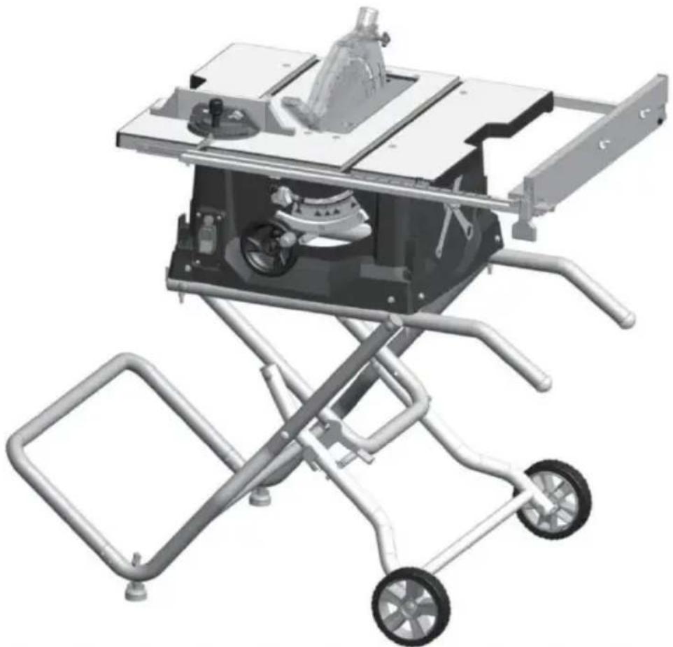
3D rendering of a mechanical cutting machine with wheels and metal frame (no text or symbols visible)NEED HELP? CONTACT US!
Have product questions? Need technical support? Please feel free contact us:
Technical Support and E-Warranty Certificate www.vevor.com/support
This is the original instruction, please read all manual instructions carefully before operating. VEVOR reserves a clear interpretation of user manual. The appearance of the product shall be subject to product you received. Please forgive us that we won't inform you there are any technology or software updates on our product.
TableofContents
GeneralSafetyRules----3
GeneralSafetyRules----4
SafetyInstructionsforTableSaws----4
SafetyInstructionsforTableSaws----5
AdditionalSafetyRules----6
MotorSpecifications&Electrical
Requirements----8
Symbols----9
GlossaryofTerms----12
UnpackingAndCheckingContents---- -14
Assembly----15
Adjustments----23
BasicTableSawOperation----26
MaintainingYourTableSaw----36
Troubleshooting----38
TECHNICALDATA----39
WARNING
Somedustcreatedbypowersanding, sawing,grinding,drilling,andother constructionactivitiescontains chemicals known to cause cancer, birth defector other reproductive harm. Some examples of these chemicals are:
. Leadfromlead-basedpaints,
. Crystallinesilicafrombricksandcement and othermasonryproducts,and
. Arsenicandchromiumfrom chemicallytreatedlumber.
Yourriskfromtheseexposuresvaries,dependingonhowoftenyoudothistypeofwork. To reduceyouexposuretothesechemicals:work inawellventilatedarea,andworkwithapproved safetyequipment,suchasthosedustmasks thatarespeciallydesignedtofilteroutmicroscopicparticles.
Avoidprolongedcontactwithdustfrom power sanding, sawing, grinding, drilling, and otherconstructionactivities.Wearprotective clothingandwashexposedareaswithsoap andwater.Allowingdusttoget intoyour mouthoreyesor tolieontheskinmaypromote absorption ofharmful chemicals.
General Safety Rules
WARNING
Read all safety warnings, instructions, illustrations and specifications with this power tool. Failure to follow all instructions listed below ma
electric shock, fire and/or serious injury.
SAVE ALL WARNINGS AND INSTRUCTIONS FOR FUTURE REFERENCE.
The term “power tool” in the warnings refers to your mains-operated (corded) power operated (cordless) power tool.
WORK AREA SAFETY
Keep work area clean and well lit. dark reas invite accidents.
under the influence of drugs, alcohol or
Cluttered. A moment of inattention while operat power tools may result in serious personal
Do not operate power tools in explosive atmosphere. Use personal protective equipment. Always spheres, such as in the presence of non-maze protection. Protective equipment suitable liquids, gases or dust. Power tools as dust masks, non-skid safety shoes, hard sparks that may ignite the dust or fumes or hearing protection used for appropriate
Keep children and bystanders away who operating a power tool. Distractions can you to lose control.
Previsit unintentional starting. Ensure the switch is in the off-position before connected to power source and / or battery pack, pin up or carrying the tool. Carrying power to
ELECTRICAL SAFETY
Power tool plugs must match the outl Never modify the plug in anyway. Do any adapter plugs with earthed (ground
power tools. Unmodifiedlugs and matching outlets will reduce risk of electric shock
atour finger on the switch or energizing pow that have the switch on invites accidents .
Remove any adjusting key or wrench before turning the power tool on. A wrench or left attached to a rotating part of the power
Avoid body contact with earthed or gr surfaces, such as pipes, radiators, rang
and refrigerators. There is an increased electric shock if your body is earthed on
roundedesult in personal injury .
Do not expose power tools to rain of ditions. Water entering a power tool will the risk of electric shock.
Do not overreach. Keep proper footing an risk of balance at all times. This enables better ground of the power tool in unexpecteds situati
Do not abuse the cord. Never use the carrying, pulling or unplugging the power. Keep cord awafrom heat, oil, sharp and moving parts. Damaged or entangled concrease the risk of electric shock.
- wet con- Dress properly. Do not wear loose clothing or increase jewelry. Keep your hair, clothing and glov away from moving parts. Loose clothes, jew elry cord for long hair can be caught in moving
When operating a power tool outdoors, an extension cord suitable for outdoor
Use of a cord suitable for outdoor use the risk of electric shock.
If devices are provided for the connection des of dust extraction and collection facilities, ensure these are connected and properly use Use of dust collection can reduce dust-relate hazards.
If operating a power tool in a damp unavoidable, use a Ground Fault Circui
rupter (GFCI) protected supply. Use of GFCI reduces the risk of electric shock
Do not let familiarity gained from frequent reduces of tools allow you to become complacent ignore tool safety principles. A careless ad location is can cause severe injury within a fraction of a sec-
PERSONAL SAFETY
Stay alert, what what you are doing an common sense when operating a power. Do not use a power tool while you
an POWER TOOL USE AND CARE Do not force the power tool. Use the power tool for your application. The corrected power tool will do the job better and safer rate for which it was designed.
SAVE THESE INSTRUCTIONS
General Safety Rules
Do not use the power tool if the switch does
not turn it on and off. Any power tool that can not be controlled with the switch is dangerous. Keep cutting tools sharp and clean. Proper and must be repaired. Maintained cutting tools with sharp cutting ends are less likely to bind and are easier to
Disconnect the plug from the power source and/or remove the battery pack, if detachable etc. In accordance with these instructions, taking from the power tool before making any adjustments, changing accessories, or storing work to be performed. Use of the power tools. Such preventive safety measures reduce the risk of starting the power tool accidentally.
Store idle power tools out of the hireach of clean and free from oil and grease. Slipp dren and do not allow persons unfamiliar with the power tool or these instructions to operate the power tool. Power tools are dangerous in the hands of untrained users. Keep handles and grasping surfaces dry, handles and grasping surfaces do not allow safe handling and control of the tool in unexpected situations.
Maintain powertools and accessories. Checkfor SERVICE misalignment or binding of moving parts. Have your power tool serviced by a qua breakage of parts and any other condition repair person using only identical replacement parts. This will ensure that the safety damaged, have the power tool repaired before power tool is maintained. use. Many accidents are caused by poor
Safety Instructions for Table Saws
GUARDING RELATED WARNINGS Make sure the saw blade is not contacting. Keep guards in place. Guards must be guard, riving knife or the workpiece before working order and be properly mounted. switch is turned on. Inadvertent contact of guard that is loose, damaged, or is not functioning the saw blade could cause a h correctly must be repaired or replaced . condition .
Always use saw blade guard, riving knife and the riving knife as described in the for every through-cutting operation. For construction manual. Incorrect spacing, positioning through-cutting operations where the saw blade and alignment can make the riving knife inc cuts completely through the thickness of the tive in reducing the likelihood of kickback. The workpiece, the guard and other safety devices help reduce the risk of injury. For the riving knife and to work, they may be engaged in the workpiece.
Immediately reattach the guarding system The riving knife and are ineffective when cutting after completing an operation (such as webbeting, dadoing or resawing cuts) which requires removal of the guard, riving knife and/or. The guard, riving knife, and help reduce the risk of injury. Under these conditions a kickback cannot be prevented by the riving knife and anti-kick device.
Safety Instructions for Table Saws
Use the appropriate saw blade for the Neving reach around or over a rotating saw knife. For the riving knife to function problade, Reaching for a workpiece may lead saw blade diameter must match the appropriate contact with the moving saw blade riving knife and the body of the saw blade must be thinner than the thickness of the riving knife and the cutting width of the saw blade must be wider than the thickness of the riving knife . and/or wide workpiece has a tendency to p
CUTTING PROCEDURES WARNINGS

Never place your fingers
hands in the vicinity or
with the saw blade. slip could direct your and result in serious
A moment of ina hand towards the personal injury .
Feed the workpiece into the saw blade motor cutter only against the direction of rotation. Feed-
ing the workpiece in the same direction, saw blade is rotating above the table of the workpiece, and your hand, being put the saw blade.
Never use the mitre gauge feed the work piece when ripping and do not use th
fence as a length stop when cross cutting with
the miter gauge. Guiding the workpiece rip fence and the miter gauge at the increases the likelihood of saw blade b kickback.
Feed the workpiece at an even pace. Do bend or twist the workpiece. If jamming cues, turn the tool off immediately, unplug saw blade tool and clear the jam. Jamming the saw by the workpiece can cause kickback or sta
emor cut- on. Feed-
Do not remove pieces of cut-off material while the saw is running. The material made it came trapped between the fence or inside saw blade guard and the saw blade pulling fingers into the saw blade. Turn the saw
wait until the saw blade stops before remov he rip material .
utting with
When the auxiliary fence in contact with the top when nipping workpieces less than 2 m thick and thin workpiece may wedge under t fence and create a kickback .
When ripping, always apply the workpiece
feeding force between the fence and the saw
blade. Use a push stick when the distance be is a sudden reaction of the workpiece between the fence and the saw blade is to less pitned, jammed saw blade or misalign 150 mm, and use a push block when of this dis- the workpiece with respect to the tance is ends than 50 mm. "Work helping blade- or when a part of the workpiece bin vices will keep your hand at a safe distance then saw blade and the rip fence or the saw blade . fixed object.
Use only the push stick provided by ufacturer or constructed in accordance with the instructions. This push stick provides the current distance of the hand from the sa
Never use a damaged or cut push s damaged push stick may break causing hand to slip into the saw blade.
Do not perform any operation "freehand Never- stand directly in line with the saw ways use either the rip fence or the Ashays position your body on the same gauge to position and guide the workpiece the saw blade as the fence. Kickback
"Freehand" means using your hands to support the workpiece at high velocity toward or guide the workpiece, in lieu of a ripofence standing in front and in line with the miter gauge. Freehand sawing leads to blade alignment, binding and kickback.
KICKBACK CAUSES AND RELATED WARNINGS
thest frequently during kickback, the workpiece wived from the table byr thportion of the saw bladfi- and is propelled towards the operator blade. Kickback is the result of saw misuse and/or
rict Operating procedures or conditions and your avoided by taking proper precautions as below .
SAVE THESE INSTRUCTIONS
Safety Instructions for Table Saws
Never reach over or in back of the saw blade PABLE SAW OPERATING to pull or to support the workpiece. Accidental PROCEDURE WARNINGS
contact with the saw blade may occur or kickback may drag your fingers into the saw blade. Turn off the table saw and disconnect the power cord when removing the table inse changing the saw blade or making adjust being cut off against the rotating saw mante. to the riving knife, antikickback de pressing the workpiece being cut off against the saw blade guard, and when the mach saw blade will create a binding condition and kick back. left unattended. Precautionary measures will avoid accidents.
Align the fence to be parallel with the Nesaw leave the table saw running unatter blade. A misaligned fence will pinch the Twink-it off and don't leave the tool until piece against saw blade and create kickback comes to a complete stop. Tended run-ning saw is an uncontrolled hazard.
Use a featherboard to guide the workpiece against the table and fence when making them through cuts such as rabbeting, dadoing where you can maintain good footing and resawing cuts. A featherboard helps to control the workpiece in the event of a kickback. It should be installed in an area to provide enough room to easily handle the
Use extra caution when making a cut into slippery floors invite accidents. blind areas of assembled workpieces. The pro-
truding saw blade may cut objects that frequently clean and remove sawdust from kickback. under the saw table and/or the dust coll
Support large panels to minimize the risk of device. Accumulate saw blade pinching and kickback an average p self-ignite.
tend to sag under their own weight. Support the table saw must be secured. A table must be placed under all portions of the panel is not properly secured may move or overhanging the table top. Remove tools, wood scraps, etc. from the
Use extra caution when cutting a workpiece table before the table saw is turned on. that is twisted, knotted, warped or does not tion or a potential jam can be dangerous have a straight edge to guide it with a miter. Always use saw blades with correct size gauge or along the fence. A warped, knotted, shape, (diamond versus round) of arbor h twisted workpiece is unstable and causes mis- bew blades that do not match the mounting alignment of the kerf with the saw blade binding and kickback .
Never cut more than one workpiece, stacked vertically or horizontally. The saw blade could pick up one or more pieces and cause kickback mounting means such asged, saw blade washers, bolts or nuts. These mounting me
When restarting the saw with the saw blade in the workpiece, center the saw blade in the ker
so that the saw teeth are not engaged in the material. If the saw blade binds, it may a lift up the stepping stool. Serious injury could occur workpiece and cause kickback when the saw is tipped or if the cutting tool is acci restarted .
Keep saw blades clean, sharp, and with sufficient use. Make sure that the saw blade is installed set. Never use warped saw blades or so that in the proper direction. Do not use blades with cracked or broken teeth. Sharing wheels, wire brushes, or abrasive
and properly set saw blades zainibinding, stalling and kickback. Wheels on a table saw. Improper saw black stallation or use of accessories not recommend may cause serious injury.
SAVE THESE INSTRUCTIONS
Additional Safety Rules
MAKE WORKSHOP CHILD-PROOF with p proper alignment with the sawblade. If rip locks, master switches. at the time, check to see if the rip fence
Use only recommended accessories. Use only accessories recommended by the manufacture. THINK OF SAFETY: Safety is a combination of your model. Other accessories maybe hazardous common sense and alertness at all time. Do not use any blade or other cutting tool when the table saw is being used.
Do not use any blade or other cutting tool marked for an operating speed less than 5000
R.P.M. Risk of serious injury .
WARNING
The operation of any power tool can result in foreign o
Ensure that blade or other cutting tool washers and arbor nut are installed properly. Reference instructions for removal and installation of the blade. . Always we
into the eyes, which
Never operate the saw unless the improper safety goggles that insert is installed. Make sure the table insert with ANSI Z87 flush or slightly below the table surface (also frontpackage) and flush to slightly above at the rear core in-sencing power

Always inspect table saw prior to every use. If any part of your saw is missing, malfunction before each use, re-
has been damaged or broken (such as the viewmod Air warnings located on the table switch or other operating control, a safety device, or the power cord), cease operate immediately TABLE SAW STAND SAFETY until the particular part is prop repaired or INSTRUCTIONS
until the particular part is prop repaired or replaced .
WARNING
Read a instructions. Fail to follow all instructions lis
Plastic and composite (hardboard) materials may be cut on your saw. However, since these are usually quite hard and pery, the may not stop a kickback. Therefore, be especially attentive to following proper set-up and cutting procedures for dropping. Do not stand, or permit anyone else to stand, in
line with a potential kickback. Turn the tool switch off and disconnect power before mounting the saw to the s Unintended startup during assembly can cause molding. Replace the guard as soon as in way op-
eration is completed.
Before operating, make sure that the entire unit is placed on a solid, level surface.
Use auxiliary facing on miter gauge to m- unit is placed on a solid, level surface. Increase stability and control. Crosscutting Serious injury could occur if the tool is un ations are more conveniently worked and with it tips .
greater safety if an auxiliary wood facing attached to the miter gauge. See "Ripiliary Facing."
Never stand on the tool or its stand or a Fencer Aux scaffolding. Serious injury could occur if the tool is tipped or the cutting to
Avoid awkward operations and hand positions. dentaily contacted . Do not store materials Where a sudden slip could cause fingers near the tool such that it is necessary to move into the sawblade or other cutting the tool or its stand to reach them .
If you stall or jam the sawblade in the workpiece, turn saw "OFF" and unplug the tool, remove the workpiece from the sawblade, and check to see if the sawblade is parallel to the table slots or grooves and if the spr
SAVE THESE INSTRUCTIONS
Motor Specifications & Electrical Requirements
Motor Specifications
If the outlet you are planning to use for
In the event of a malfunction or breakdown, is of the two-prong type, DO NOT REOR ALTER THE GROUNDING PRONG IN A MANNER. Have a qualified electrician the plac This tool is equipped with an electric cord with an equipment-grounding conductor and a ground-plugs. Three-prong outlet. Do not use any adapting plug. The plug must be plugged into a match-
ing outlet that is properly installed and graprodel connection of the equipment-groundin accordance with all local codes and ordinary conesctor can result in a risk of electric sl This saw is wired for operation on 120 conductor with insulation having an outer sur alternating current. Before connecting the thabdis green with or without yellow stripes cord to a power source, make certain the equipment grounding conductor. If repair or switch is in the "OFF" position and be placement die the electric cord or plug is n electric current is of the same characterist does not connect the equipment grounding cor that stamped on the table saw nameplateor. to a live terminal.
Connection To A Power Source
Check with a qualified electrician or service sonnel if the grounding instructions are not pletely understood, or if in doubt as to wh tool is properly grounded.
This machine must be grounded while in protect the operator from electric shock.
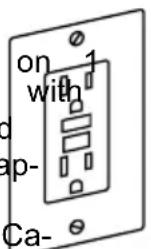
Plug the power cord into a 120Vproperly type outlet protected by a 15-amp dual-time-delay fuse or circuit breaker.
Not all outlets are properly grounded. I sure that your outlet, as pictured on this properly grounded; have it checked by a electrician.
WARNING
To avoid electric shock do not touch the metal prags
on the plug when installing or removing plug to or from the outlet.
WARNING
Failure to properly ground this power tool can cause
electrocution or serious shock, particularly when used near metal plumbing or other objects. If shocked, your reaction could be your hands to hit the tool.
WARNING
If power cord is worn, c damaged in any way, hav
replaced immediately to avoid shock or hazard.
Your unit is for use volts and is equipped a 3-conductor cord and grounding type plug, a proved by Underwriters Laboratories and the Canadian Standards Association
ation . The ground conductor has a green jacket and is attached to the tool housing at one end and to the ground prong in the attachment plug at the other end .
grounded element
Extension Cords
WARNING
Replace damaged cords immediately. Use of damaged
It you are not cords can shock, burn or electrocute .
WARNING
Always use proper extension cords. Use only 3-wire exten
sion cords which have 3-prong grounding plugs and 3-pole receptacles which accept tool's plug. If an extension cord isy, necess
with adequate size conductors should be used to prevent excessive voltage drop, loss
power or overheating . The table shows thesize to use, depending on cord length andplate amperage rating of the tool . If in clythe next heavier gauge . Always use U .Llisted extension cords .cause
RECOMMENDED SIZES OF EXTENSION CORDS 120 VOLT ALTERNATING CURRENT TOOLS cut or
| ve itTogel'sAmpereRating | Cord Size in A.W.G. Wire Sizes ^2 in | |||||||
| Cord Length in Feet | Cord Length in Feet | |||||||
| 25 | 50 | 100 | 150 | 15 | 30 | 60 | 120 | |
| 3-6 | 18 | 16 | 16 | 14 | 0 .7 | 50 .75 | 1.5 | 2.5 |
| 6-8 | 18 | 16 | 14 | 12 | 0 .7 | 51.0 | 2.5 | 4.0 |
| 8-10 | 18 | 16 | 14 | 12 | 0 .7 | 51.0 | 2.5 | 4.0 |
| 10-12 | 16 | 16 | 14 | 12 | 1.0 | 2.5 | 4.0 | - |
| 12-16 | 14 | 12 | - | - | - | - | - | - |
NOTE: The smallerthe gauge number, the h
Symbols
Safety Symbols
The purpose of safety symbols is to attract your attention to possible dangers . The and the explanations with them deserve your careful attention and understanding . Th warnings do not, by themselves, eliminate any danger . The instructions and warnings no substitutes for proper accident prevention measures .

Be sure to read and understand all safety instructions in this Own Manual, including all safety alert symbols such as "DANGER,"
"WARNING," and "CAUTION" before using this tool. Failure to following all instru listed below may result in electric shock, fire, and/or serious personal injury.
| The definitions below describe the level of severity for each signal word. Please read pay attention to these symbols . | |
 | This is the safety alert symbol . It is used to alert you to injury hazards. Obey all safety messages that follow this symbol to possible injury or death . |
 | DANGER indicates a hazardous situation which, if not avoided, in death or serious injury . |
 | WARNING indicates a hazardous situation which, if not avoided, result in death or serious injury . |
 | CAUTION, used with the safety alert symbol, indicates a hazardous situation which, if not avoided, will result in minor or moderate injury . |
Damage Prevention and Information Messages
These inform the user of important information and/or instructions that could lead to other property damage if they are not followed. Each message is preceded by the as in the example below:
NOTICE: Equipment and/or property damage may result if these instructions are not followed.

natural_image
Icon of a person wearing glasses inside a black circle (no text or symbols)
The operation of any power tools can result in foreign objects being thrown into your eyes, which
can result in severe ey damage. Before beginning power tool operation, always wear safety goggles or safety glasses with side s and a full face shield when needed . We recommend a Wide Vis Mask for use over eyeglasses or standard safety glasses with side shields . Always use eye protection which is marked to comply wit Z87.1.
Symbols
IMPORTANT: Some of the following symbols may be used on your tool. Please select learn their meaning. Proper interpretation of these symbols will allow you to operate and more safely.
| Symbol | Name | Designation/Explanation |
| V Volts | Voltage (potential) | |
| A | Amperes | Current |
| Hz Hertz | Frequency (cycles per second) | |
| W | Watt Power | |
| kg Kilograms | Weight | |
| min | Minutes Time | |
| s | Seconds | Time |
| Wh | Watt-hours | Battery capacity |
| Ah Ampere-Hours | Battery capacity | |
| ∅ | Diameter | Size of drill bits, grinding wheels, etc. |
| n0 | No load speed | Rotational speed, at no load |
| n | Rated speed | Maximum attainable speed |
| .../min | Revolutions or reciprocation per minute | Revolutions, strokes, surface speed, orbits, etc. per minute |
| 0 | Off position | Zero speed, zero torque... |
| → | Arrow | Action in the direction of arrow |
| ~ | Alternating current | Type or a characteristic of current |
| --- | Direct current | Type or a characteristic of current |
 | Risk of injury symbol | Do not reach into the running sa |
 | Read manual symbol | Alerts user to read manual |
 | Wear eye protection symbol | Always wear safety goggles or safety with side shields and a full face shie operating this product . |
 | Wear a mask | Recommendation for the operator to wear dust mask . |
 | Wear ear protection | Recommendation for the operator to wear hearing protection . |
Symbols (Certification Information)
IMPORTANT: Some of the following symbols for certification information may be used tool. Please study them and learn their meaning. Proper interpretation of these sy you to operate the tool better and more safely.
| Symbol Designation/Explanation | |
 | This symbol designates that this tool is listed by Underwriters Lab |
 | This symbol designates that this tool is recognized by Underwr Laboratories . |
 | This symbol designates that this tool is listed by Underwriters to United States and Canadian Standards . |
 | CE Certification |
Glossary of Terms
ARBOR: The shaft on which a cutting mounted.
MOLDING: A non-through cut which produces a special shape in the workpiece; used for ing or decoration.
BARRIER GUARD: An assembly that consists
of the mounting fork and two side barrier NON THROUGH SAWING: Any cutting opera assembly is intended to provide a physical bawhere the blade does not extend throu rier between the operator and the spinning the saworkpiece (e.g. Dado, Rabbet). blade . PARALLEL: Position of the rip fence equal
BEVEL: Blade angle relative to the table face.
PARALLEL: Position of the rip fence equal
distance at every point to the side face of saw blade.
CROSSCUT: A cutting or shaping operation made across the width of the workpiece, the workpiece to length.
PERPENDICULAR: 9 (right angle) intersection cutting position of the vertical and horizontal planes such as the position of the saw blade (vertical) to the table surface (horizontal).
DADO: A non-through cut that produces square-sided notch or trough the workpiece
PUSH BLOCK: A device used for ripping-type
FEATHERBOARD: A device that can help guide workpieces during rip type operation keeping the workpiece in contact with the fence. It also helps prevent kickback.
operations that is too narrow to allow use Push Stick. Use a Push Block for rip wi by less than 2 inches.
FREEHAND: Performing a cut without a miter gauge, fixture, hold down or other device to keep the workpiece from twisting during the cut and can be a safety hat
PUSH STICK: A device used to feed the
fence, through the saw during narrow rip- ping-type operations that helps keep the operator's hands well away from the bl lase the Push Stick for rip widths of less than 6 inches and more than 2 inches . wood
GUM: A sticky, sap-based residue from products. After it has hardened, it is as "RESIN."
RABBET: A notch in the edge of a workp Also called an edge dado .
HEEL: Misalignment of the blade that cau the trailing or outfeed side of the blade the cut surface of the workpiece. Heel kickback, binding, excessive force, burning the workpiece or splintering. In general, creates a poor quality cut and can be hazard.
REVOLUTIONS PER MINUTE (R.P.M.): The number of turns completed by a spinning o can cause in one minute . of
KERF: The space in the workpiece when material was removed by the blade.
Ripping: A cutting operation along the length of safetyworkpiece cutting the workpiece to w
KICKBACK: An uncontrolled grabbing and throwing of the workpiece back toward th of the saw during a ripping operation.
RIVING KNIFE OR SPREADER: A device th keeps the kerf of the work piece open as material is cut. This minimizes the potential the wr piece binding against the saw blade
LEADING END: The end of the workpiece which, during a ripping-type operation, is into the cutting tool first.
Blade Guard: Made up of 2 com- ponents: Riving Knife / Splitter, and Main Barrier Guard
THROUGH SAWING: Any cutting operation where the blade extends through the work-piece.
WORKPIECE: The item on which the cutting operation is being performed. The surfaces a workpiece are commonly referred to as faces, ends and edges.
Getting To Know Your Table Saw
1. RAIL
Move the fence to the desired position.
8. RAIL LOCK HANDLE
Allows you to lock the fence at desired tances.
2. MITER GAUGE
Head can be locked in the desired po for crosscutting or mitering by tightening lock knob. ALWAYS SECURELY LOCK WHEN IN USE.
- Lock/release lever
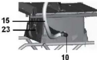
10the Dust chute
Removable to clear pieces of wood trappes inside.
3. Blade Guard
Consists of two key elements: Riving and Barrier Guard Device.
- Power cord wrap posts
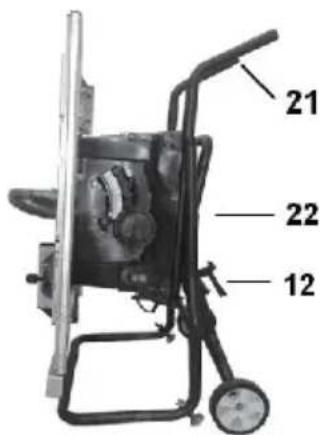
K12 Stand release latch
-
Folding stand
-
Riving knife
-
Suction hose
-
Blade height / Bevel angle adjust wheel
-
Switch
-
Reset
-
^both Bevel angle lock
-
Push stick
-
Carry handles (folded position)
-
Stand in folded position
-
Wrenches
4. Table insert
Removable for removing or installing a or other cutting tools.
5. Rip fence assembly
Provides an auxiliary support . Securely attaches to rails with locking latches o ends .
6. Right extension table
Provides support for wider workpieces extending the fence beyond the table
7. TABLE
Provides large working surface to support the workpiece.
natural_image
Close-up of a mechanical component or assembly with no visible text or symbols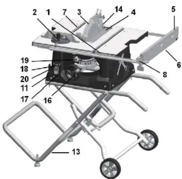
UnpackingAndCheckingContents
WARNING To avoid injury from unexpected starting electrical shock during unpacking and setting up, do not plug the power cord into a source of power. This cord must remain unplugged when every you are assembling or making adjustments to the tables aw withstand.
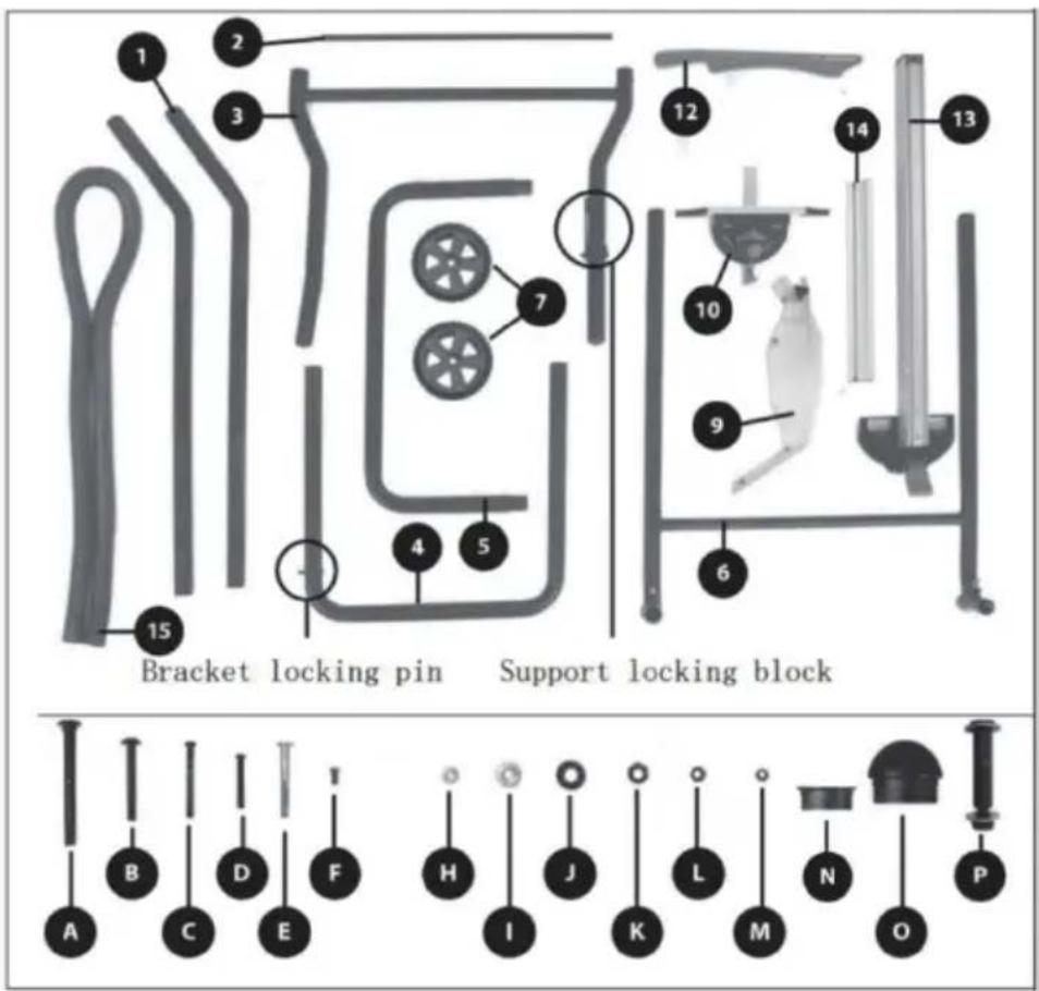
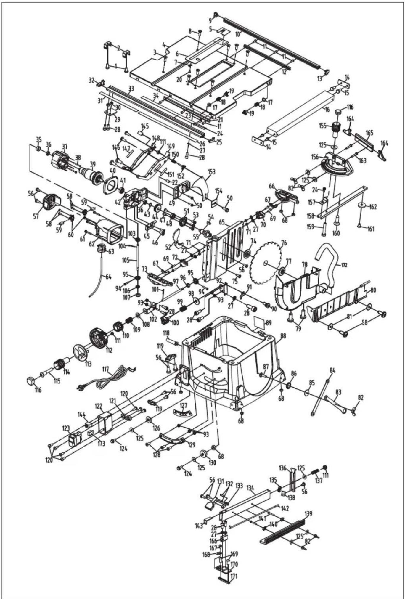
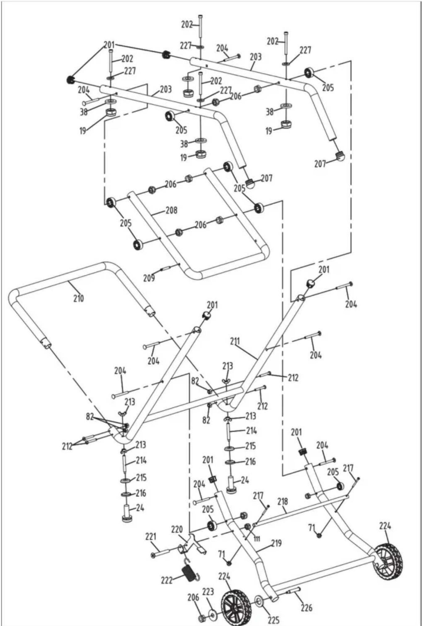
Separateallpartsfromthepackingmaterials andcheckeachonewiththeillustrationand thelistofLoosePartstomakecertainthatall itemsareaccountedforbeforediscardingany packingmaterial(Fig.3).
WARNING Ifany partsar emiss ing,do notat temptto assemble the tablesaw,pluginthepowercordorturnthe switchonuntilthemissingpartsareob tained andareinstalledcorrectly.
TABLEOFLOOSEPARTS
TableSaw\*1
- Support component 1 * 2
- Support component 2^*1
- Support component 3 * 1
- Support component 4 * 1
- Bracket assembly 5^*1
- Support component 6 * 1
- Support wheel * 2
- Saw blade guard * 1
- Miter gauge * 1
12.Push stick * 1
13.Rip fence * 1
14.Fence*1 - Dust pipe* 1
A.M8*83mmscrew*8
B.M6*75mmscrew*4
C.M5*50mmscrew*2
D.M5*40mmscrew*4
E.M6*55mmscrew*2
F.M5*10mmscrew*1
H.Smallgasket*2
I. Largegasket*4
J.Spacerblock*8
K.M8Nut*8
L.M6Nut*4
M.M5Nut*7
N.FLATENDCAPS*6
O.Roundtubeendcap*2
P.Wheelarbor*2
Assembly
The Table Saw is designed for job site use. This unit sets up and folds quickly, and is ea loaded or unloaded by one person into a truck
TOOLS REQUIRED:
Cross head screwdriver, 8mm and 10mm wrench or socket wrench, 13mm socket wrench, 5mm hex wrench, and rubber hammer.
BEFORE YOU ASSEMBLE THIS TABLE SAW STAND:
Sort out and account for all parts to make sure that you have all the necessary materials to assemble your stand. Do not discard packing material until all parts are counted for.
Warning! Due to the weight of the machine, handling or moving during the assembly process requires cooperation from two people
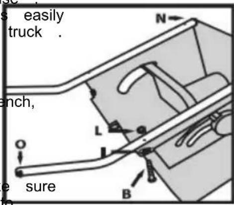
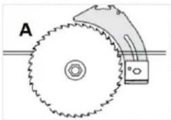
Figure A
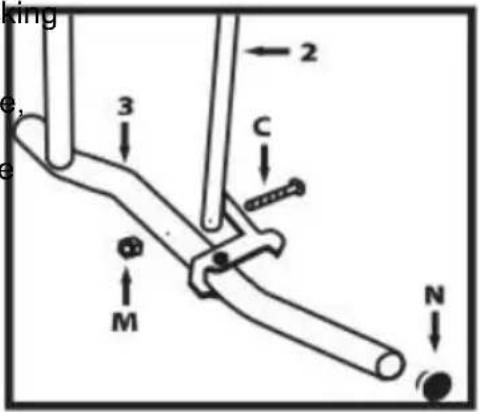
Figure B
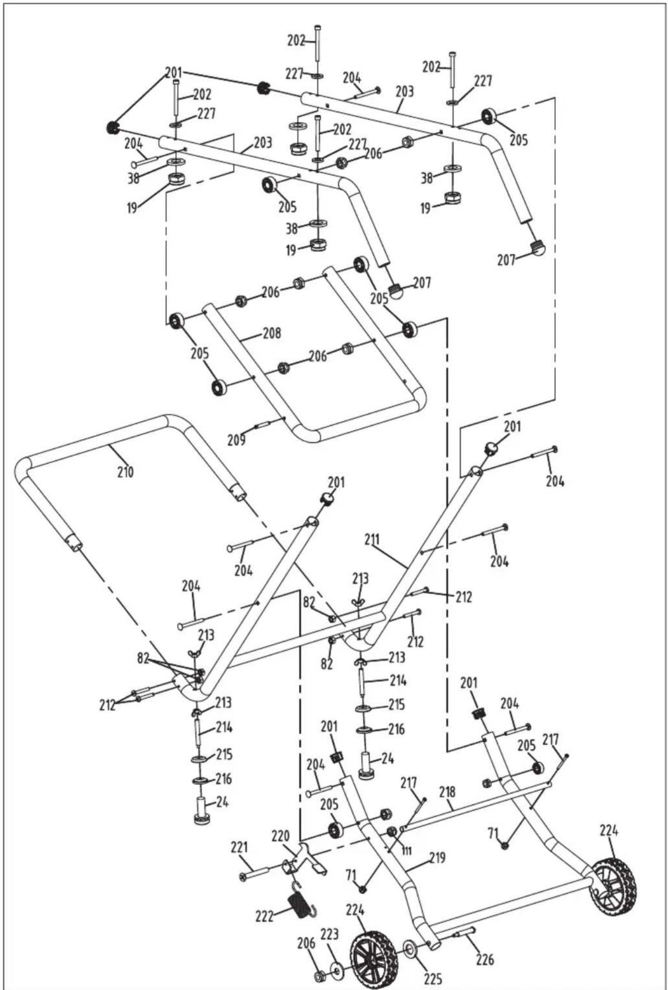
STEP1
- Invert the host on a sturdy and clean workbench/bracket.
- Take out Two legs 1#
- Use accessories B #, I #, and # L to assemble the two legs 1 # onto the host machine
- Use a round end cover to cover the foot handle end(Figure A)
STEP2
Assemble parts 2 # and 3 # together using accessory bolts C # and nuts M # (Figure B). Select two end capeledabN and push them into the straight ends of the components.
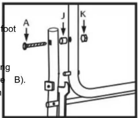
Figure C
STEP3
- Remove parts 3 # and 4#
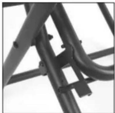
- Use accessories A #, J #, and K # to assemble one side of 4 # and part 3 #, and tighten the bolts appropriately. Complete the assembly on the other side using the same steps (Figure C). The spacing block J # needs to maintain sufficient interval to facilitate the movement of the entire bracket
- Ensure that part 4 # is installed correctly and that the bracket lock block on part 3 # and the bracket lock pin on part 4 # are correctly paired S(Figure D)
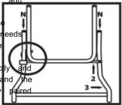
Figure D
Assembly
STEP4
- Assemble part 4 # onto the machine, ensuring that the bracket lock block, lock pin, and saw blade lifting/side cutting adjustment handwheel are on the same side of the main body (Figure E)
- Adjust accessories A #, J #, and K # ensure fast spacing. J # is placed correctly and has appropriate clearance to ensure smooth movement of the entire bracket
- Repeat the above steps to assemble the other side of part 4 onto the main body (Figure F).
STEP5
Take out parts 5 # andd 6us#, an accessories D# and M# to assemble 5# onto 6 # (Figure G)
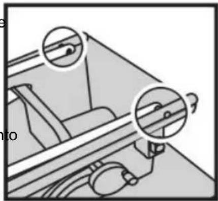
STEP6
- Assemble part 3 using accessories A, J, and K (Figure H) and other machine legs together. Moving part 4 slightly away will aid in the assembly process
- Carefully move parts 3 and 6 to align the screw holes for easy insertion of the screws (Figure I)

Figure E
natural_image
Mechanical assembly diagram showing two circular components with arrows indicating motion or force directions (no text or symbols)Figure F
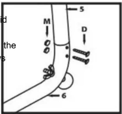
Figure G
Figure H
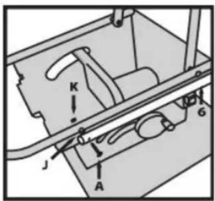
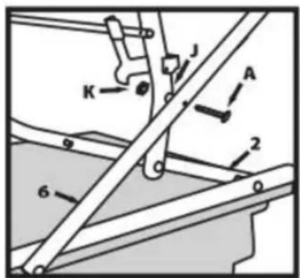
Figure 1
Assembly
STEP7
- Install the support wheel of part 7 # onto
part 3 # and secure it with the accessory bolt P # (Figure J) on part 3 #. Avoid tightening the bolts too tightly to allow the wheels to rotate freely.
- The bracket installation is completed.
Please seek help from others to flip the body over, do not flip it yourself

Figure J
Attention: Two people are required to assist in moving and deploying/retracting the support feet when the machine has a large self weight
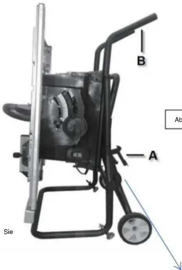
Accessory storage and idfog/unfolding
stand (Figure K)
Note: Before folding stand, remove all workpieces from the table. Remove and securely store all loose accessories such as the miter gauge, rip fence, blade guard, and push stick. Lower saw blade below the tabletop.
Folding stand for storage and
transportation purposes(Figure K)
- Push the stand release latch (A) and at the same time, grasp the stand handles (B) and lift them up and away from the saw body
2.Push the job site saw until as the rele latch clicks and locks the stand.
Unfolding stand for use at the jobsite
- Push the stand release latch (A) and at the same time, grasp the stand handles (B) and pull them down towards you.
2.Push down until the release latch clicks and locks the stand.
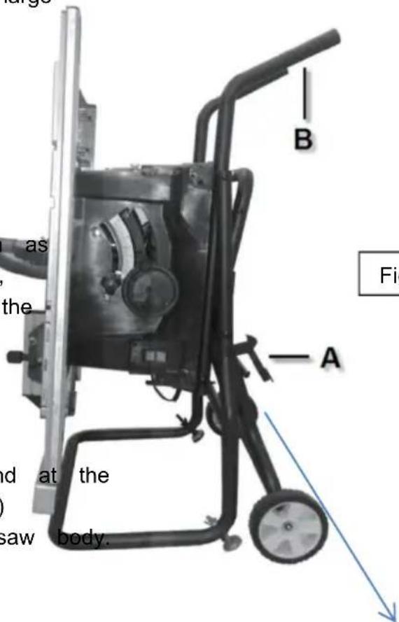
Figure K
natural_image
Close-up of a metal bracket with bolts and joints (no text or symbols visible)Assembly
ATTACHING THE Blade Guard
WARNING
To prevent personal in
always disconnect the plug
from the power source before attaching or removing the Blade Guard.
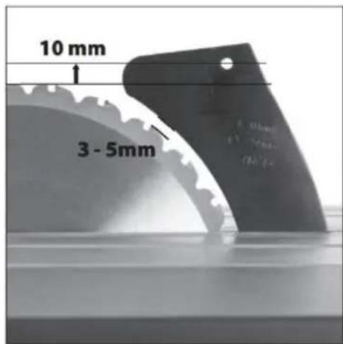
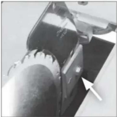
POSITIONING THE RIVING KNIFE
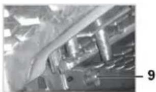
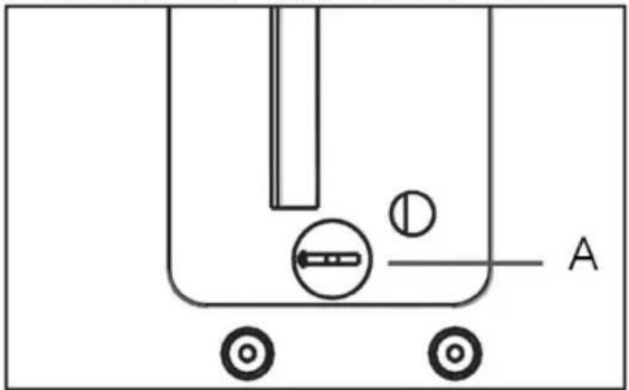
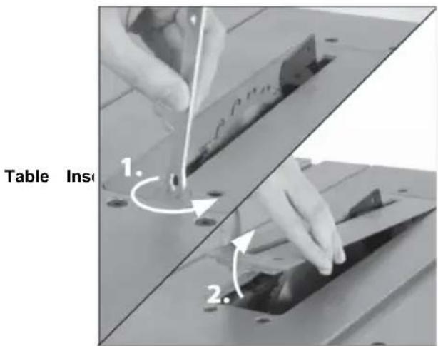
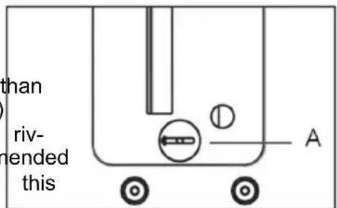
- Remove the table insert using finger hole (Fig.
- Raise the blade as high as it will go and perpendicular to table ( 0^ on bevel scale) (Fig. 6).
- Loosen the Riving Knife fixing bolt by several turns and raise it to its highest point (Fig. 6).
4• Slide the Riving Knife (it is slotted for convenience) between the fixing plate and mounting blockFig. 6). .Ensure that the mounting blocks projecting lugs engage with the slot in the Riving Knife.
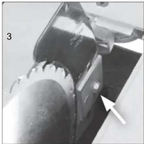
5• Adjust the Riving Knife so that it is between - 5mm from the saw blade. The blade guard mounting hole on the riving knife should be at least 10mm higher than the tooth peak. (Fig. 7).
6• When correct alignment is achieved tighten the fixing bolt.
7- Check the saw blade rotates freely and teeth are within
3 - 5mm of the Riving Knife.
8• Re-install the Table Access Plate.
natural_image
Simple line drawing of a container with wheels and a labeled point A (no text or symbols beyond label)FIG.5
Riving Knife
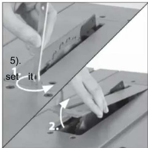
FIG.6
natural_image
Close-up of a mechanical component with a white arrow pointing to a specific area (no visible text or symbols)FIG.7
Assembly
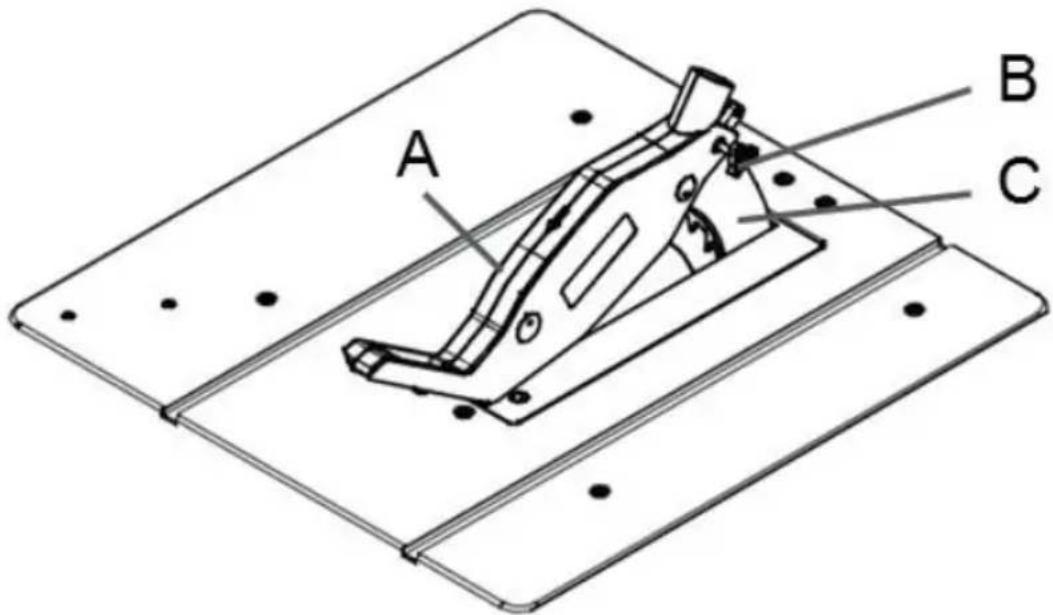
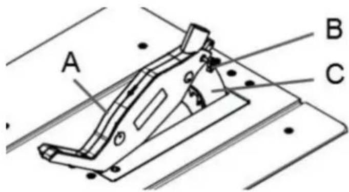
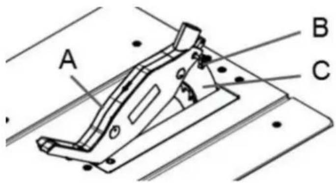
ATTACHING THE GUARD ASSEMBLY
The Blade Guard must be attached to the Kline(3).Check the purely connected
machines
riving knife.
Note: The machine should never be used
without this guard in
its service position.
WARNING: The machine must be
disconnected from the
mains supply when installing the blade gu
the bolt is firmly seated in the slot of th
knife(C).Check that the guard assembly is s
curely connected
Do not screw in the bolt(B) too tightly; th
blade guard(A) must move freely.
Plug the suction hose onto the suction ada
and the connecting piece of the saw
blade guard(A). Connect a suitable splint
collector onto the suction adapter.
Disassembly is performed in reverse order.
Caution! The saw blade guard(A) must be
lowered onto the workpiece before
so that starting the sawing operation.
Assembly
REMOVAL AND INSTALLATION
OF THE BLADE
WARNING Disconnect the plug from power source before performing any assembly, adjustment or avoid possible injury.
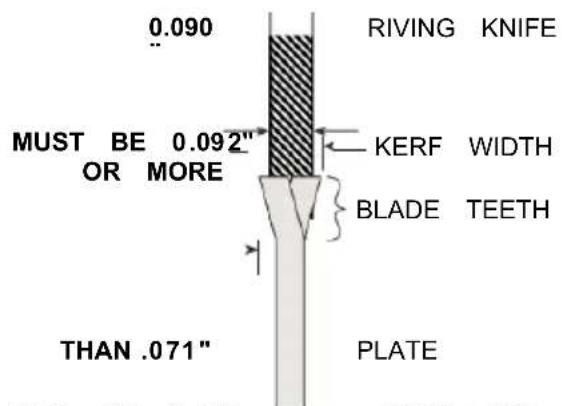
USING THE CORRECT BLADE
IMPORTANT: The saw blade provided on with the riving knife / splitter, which may be tool has a diameter of 10 inches. When working piece during cutting. One "stabilizer" plate for a replacement blade, select one with mamber placed only in the outside of a th sions close to the original blade. This replacement blade. These plates are not re may not be printed on the blade's packaging. The supplied blade.
is not, check the manufacturers catalog or website .EVOR offers Premium-Quality Profes-
CHANGING THE BLADE
sional saw blades that match the requirements for this tool. You must select a blade with installation width of .092" or more and a plate (body) thickness
.088" or less (Fig . 10) .
FIG.1
FIG.
MUST BE LESS → BLADE BOI
WARNING
To reduce the risk injury do not use extran khrf saw
blades. The kerf of the blade must be wider than .092 Extra thin kerf saw blades (less than .092") may cause the work piece to bind against the riv-ing knife / splitter during cutting . It is recommended that the kerf of the replacement blade used on this saw be .092" or more .
WARNING To reduce the nsk of injury do no use savblade smade
with a thick body plate. If the replacement saw blade's plate thickness is greater than .071" the riving knife / splitter would not properly serve as up as high as it will go. The replacement blade's plate thickness must be less than .071" 3.Remove table insert.
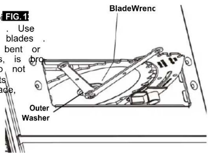
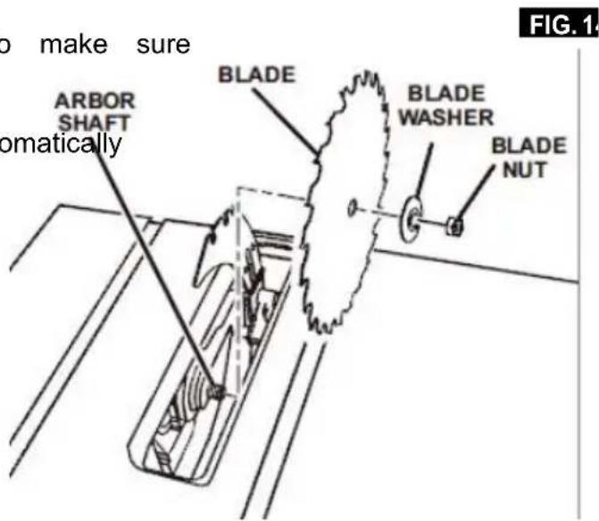
- Insert the open-head hex wrench onto the shaft. While holding the first
wrench, loosen the arbor screw counterclock with the ring-head hex wrench.
- Remove the arbor screw and outer wa blade may now be removed or installed
by sliding it onto or off the arbor shaft.
- Assemble the inner washer, new blade, outer washer and arbor nut as shown. (Fig . 14)
making certain that the TEETH OF THE BLADE ARE POINTING DOWN AT THE FRONT OF THE TABLE.
- While holding the arbor shaft with the open-head hex wrench, use the ring-head
hex wrench to securely tighten the arbor nut clockwise. (Fig . 13)
- Install table insert.
NOTE: The printing on different saw blades is not always the same side.
To avoid injury from a thrown workpiece, blade part, or blade contact, never operate the saw without the proper insert in place. Use the table insert when sawing. Use the dado insert when using a dado blade.
Assembly
USING CARBIDE-TIPPED BLADES
Handle carbide-tipped blades carefully . Carbi FIG.1 is very brittle and can be easily damaged . Use caution when you install, use or store the blades . Do not use a carbide-tipped blade that is bent or has bent teeth, or if the blade has cracks, is broken, or has missing/loose carbide tips . Do not operate a carbide-tipped blade faster than its recommended speed . When selecting a blade, ensure it is rated above 5000 rpm .
Read, understand, and follow warnings and instructions provided with your carbide-tipped blades.
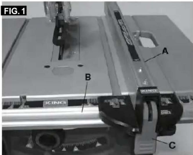
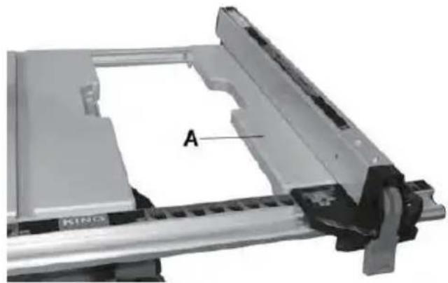
ATTACHING RIP FENCE FOR USE
-
Position the front of the rip fence(A) on the front rail (B). Lower the back end of the rip fence on the rear rail. Check to make sure the rip fence slides freely on the rails.
-
Lower rip fence locking lever(C) to automatically align and secure the rip fence in place.
See Fig . 15 .
Adjustments
Adjusting the extendable extension table(Fig. 9) extension to the desired width. Use the sc & Fig. 10) on the front rail when a specific width
The extension table allows the user to increase
the length of the table for greater 3. Once the extension is in the desired position, tighten the lock lever(B) to secure
- Unlock or remove the rip fence from the table. The extension in place. The rip fence can be installed as shown in.
- Unlock the extension table(A) by loosen the extension lock lever (B) slide the 4. Lock lever(B) is under the table.
natural_image
Mechanical assembly component with labeled section A, no visible text or symbols beyond label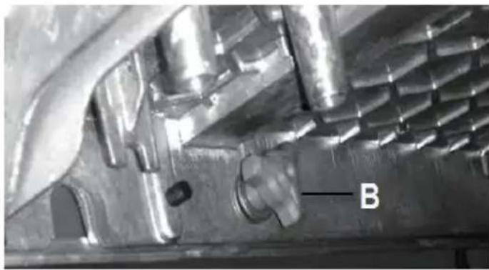
natural_image
Close-up of a metallic mechanical component with internal cavities and a labeled feature 'B' (no readable text or symbols beyond label)Adjustments
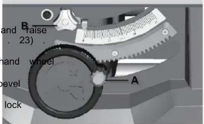
Adjusting the blade height
WARNING
To prevent personal injury always dis connect the plug from the power source when making adjustments.
Note: A 90° cut has a 0° bevel angle and a 45° cut
has a 45^ bevel angle
-
Turn the elevation wheel clockwise the blade to its maximum height (Fig 2. Unlock the bevel locking lever (B).
-
Push in and then turn the exterior (A) to adjust the blade bevel angle, turning it counterclockwise increases the angle of the blade.
-
Once the desired angle is achieved, the bevel locking lever(B)
FIG.2
Adjustments
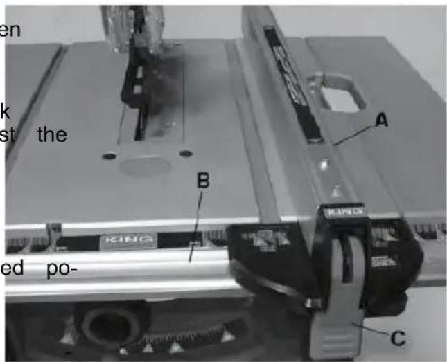
ALIGNING RIP FENCE
WARNING To prevent personal injury always disconnect plug FIG.29
from the power source before making any adjustments.
The rip fence must be parallel with the sawblade in order to prevent KICKBACK when ripping.
When moving the rip fence, make sure to unlock and lock the fence with the rail lock handle and use the front rail knob to adjust the fence position.
WARNING
To prevent personal injury always make sure that the
rip fence is locked before making rip cuts.
-
Lift both guard barriers to their up locked position (Fig 29).
-
Turn the elevation wheel and raise the blade as high as it will go.
-
Align the blade to the miter gauge slots per instructions: ADJUSTING BLADE PARALLEL TO THE MITER GAUGE SLOTS.
4 . ADJUSTING BLADE PARALLEL TO THE RIP FENCE .
- Secure the lock levers on both sides of the fence.
Basic Table Saw Operation
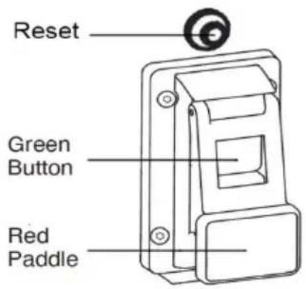
SAFETY POWER SWITCH
NOTE: This table saw has a safety fea that helps prevent accidental starting . W power is cut to the saw, the tool will the off mode . Once power is restored, tool will need to be turned on again .
To turn saw on: Press the green button (Fig . 39) .
To turn saw off: Press the red paddle (which depresses the red off switch underneath) (Fig . 39). RESET BUTTON (POWER RESET)
This saw comes with an overload reset button, If the saw motor overloads, a safety
mechanism stops the motor switch to the automatically due to motor over- loading or low voltage.
To prevent motor overload, reduce load on motor or check voltage. Allow motor to cool down, then press the reset button and restart the saw. If the saw does not restart, wait an additional 5 minutes before restarting.
Basic Table Saw Operation
USING THE Blade Guard
The Blade Guard has been designed for modularity, enabling the use of multiple c binations of the two main components - Riving Knife / Splitter, 2) Main Barrier C
(Fig . 41) . Any Blade Guard that need to be
removed to complete a cut should be immediately reinstalled when finished. See
"Attaching the Blade Guard" for detailed installation instructions. AI-ways remem that the best accident prevention is the
operator's use of common sense and at all isn when using the table saw.
NOTE: To best secure the main guard for relocation, adjust the blade to its low-est position. This keeps the guard tight to the table surface and prevents dam-age related to the guard swinging during relocation.
BLADE BEVEL CONTROL
The blade height should be set higher (above) the top of the work-piece to cut.
Turn the round handle(A) to set the blade to the inertness required depth.
- Anticlockwise: smaller cutting depth
- Clockwise: larger cutting depth.
natural_image
Diagram of a mechanical gear system with labeled point A, showing toothed circular components and a rotating shaft (no text or symbols beyond label)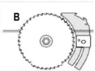
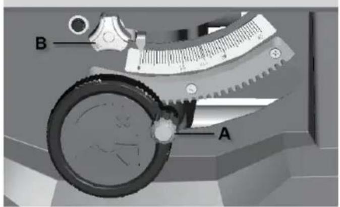
natural_image
Diagram of a gear and cam mechanism with labeled component B (no text or symbols on the diagram itself)FIG.42

Basic Table Saw Operation
WORK HELPERS
Before cutting any wood on your saw, study all of Workpiece the "Basic Saw Operations."
Notice that in order to make some of the cuts, it is necessary to use certain devices, "Work Helpers," like the Push Stick, the Push Block and the Auxiliary Fence, which you can make yourself.
After you have made a few practice cuts, make 1/4 → these “helpers” before starting any projects. Make the “Push Stick” first. (A push stick is included with the).
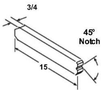
PUSH STICK AND PUSH BLOCK FIG.45
Makethe push stick usinge aof pi¢ x 2 as shown 4-3/4 (Fig . 44)
Make the push block using pieces of 3/8" plywood A and 3/4" hardwood B (Fig . 45) .
The small piece of wood, 1/2" x 3/8" x should be GLUED to the plywood... DO USE NAILS. This is to prevent dulling blade in the event you mistakenly cut in block.
Position the handle in the center of the plywood and fasten it together with glue and woodscrews.
Use a push stick whenever the fence is 2 inches or more from the blade. Use a push eblock when the operation is too narrow to allow the use of a push stick. For proper use, see "Ripping" and "Bevel Ripping sections."
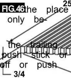
The push stick or block should be used FIG.46 the place of the user's hand to guide the material only between the fence and blade.
When using a push stick or push block, end of the board must be square. A block against an uneven end could slip the work away from the fence.
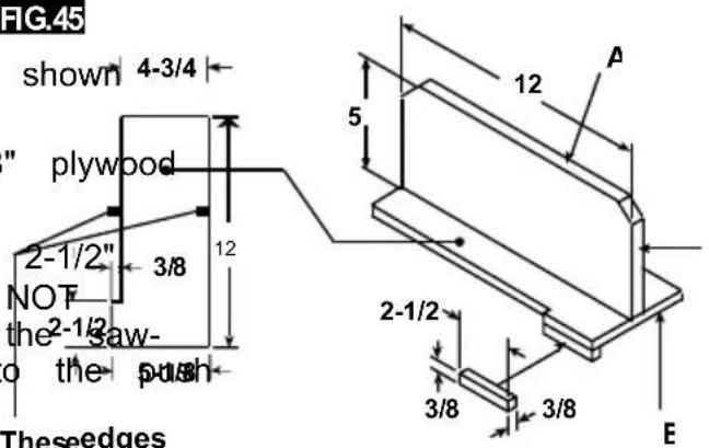
Theseedges plywood mustbe parallel
NOTE: All dimensions in inches.
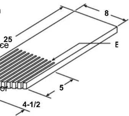
MAKING A FEATHERBOARD
Figure 46 illustrates dimensions for ingaka typical featherboard. It should be made from a straight piece of wood that is free of knots or cracks. Kerf E should be about 1/4"
Basic Table Saw Operation
WARNING
Always wear hearing pro 10 tion during cutting, and gloves
when handing saw blades.
USING THE RIP FENCE
. Do not pick up small pieces of cut-rial from the table . REMOVE them by ing them OFF the table with a long st Otherwise they could be thrown back at by the rear of the blade .
RIPPING, BEVEL RIPPING, RESAWING AND
RABBETING are performed using the RIP 'FE together with the AUXILIARY FENCE / WORI
SUPPORT, PUSH STICK OR PUSH BLOCK
Do not remove small pieces of cut-of trial that may become TRAPPED inside t blade guard while the saw is RUNNING THIS COULD ENDANGER YOUR HANDS
WARNING
For your own safety, always observe the following safety
precautions, in addition to the safety instructions on Pages 3, 4, 5 & 6. remove the piece.
- Never make these cuts FREEHAND (with- If the workpiece is warped, place the out using the rip fence or auxiliary devices CAVE side DOWN. This will prevent it when required), because the blade could rocking while it is being ripped.
bind in the cut and cause a KICKBACK
RIP FENCE AUXILIARY FACING
- Always lock the rip fence securely when using dado accessories, an auxiliary placing board should be used. This will help
- Remove miter gauge from table during damage to the aluminum fence. The facing operations that utilize the rip fence. should be made of 3/4 inch thick wood (F
- Make sure that the blade guard is installed for Parts Required:
all through sawing type cuts. Replace 3/4th guard IMMEDIATELY following completion size of
resawing, rabbeting, or dadoing operations
Two (2) clamps .
- Have the blade extend approximately 1/8" above the upper surface of workpiece tional blade exposure would increase the hazard potential. The facing is made to the same height (2) as the fence and can work with the blade system in place when moving the fence to test the blade, while two clamps to claim
- Do not stand directly in front of the blackboard in wood board to the rip fence. case of a KICKBACK. Stand to either side of
NOTE: The auxiliary facing board, should also be used when cutting material less than 3/
- Keep your hands clear of the blade and out of the path of the blade.
- If the blade stalls or stops while cutting, TURN THE SWITCH OFF before attempting to free the blade.
- Do not reach over or behind the blade to pull the workpiece through the cut, to support long or heavy workpieces, to remove small cut-off pieces of material, or FOR ANY OTHER RISON.
FIG. 49
Basic Table Saw Operation
RIPPING
FIG.50
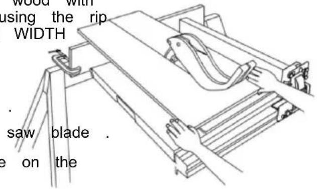
RIPPING is known as cutting a piece of wood with the grain, or lengthwise. This is done using the rip fence. Position the fence to the desired WIDTH OF RIP and lock it in place.
Before starting to rip, be sure:
A. Rip Fence is parallel to saw blade.
B. Riving knife is properly aligned with saw blade
Position the wider portion of the workpiece on the side of the fence.
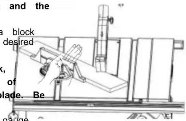
BEVEL RIPPING
Avoid bevel ripping with the fence on the side, when possible. When bevel ripping 6" or mower, use the fence on the right the blade ONLY. This will provide more between the fence and the sawblade for push stick. If the fence is mounted to sawblade guard may interfere with proper a push stick.
When "WIDTH OF RIP" is 6" and WIDER use your RIGHT hand to feed the workpiece, use LEFT hand ONLY to guide the workpiece, do not FEED the workpiece with the left hand (Fig . 50).
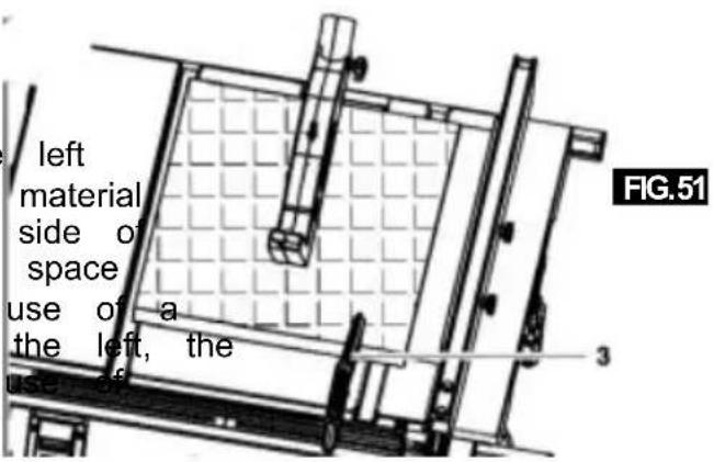
When "WIDTH OF RIP" is 2" to 6" wide USE THE PUSH STICK to feed the(Figor. 51).
When WIDTH OF RIP is NARROWER than 2" the push stick CANNOT be used because the guard will interfere. USE the AUXILIARY FENCE, and PUSH BLOCK.
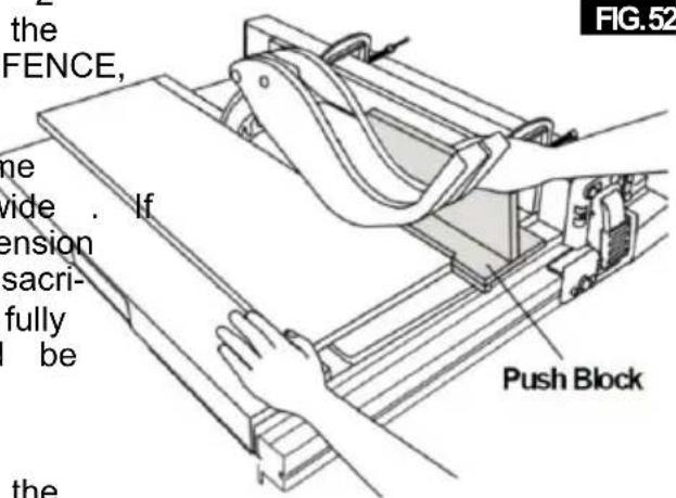
The auxiliary fence should be used any time the "WIDTH OF RIP" is under 6 inches wide. the "WIDTH OF RIP" is of a smaller dimension than the height of the workpiece, then a sacrificial auxiliary fence of adequate height to fully support the workpiece during the cut should be made and attached to the fence.
Feed the workpiece brand until the end is approximately . 1" from the front edge of the table . Continue to feed using the PUSH BLOCK on top of auxiliary fence UNTIL THE CUT IS COMPLETE (Fig . 52) .
Basic Table Saw Operation
NOTE: When bevel crosscutting, attach the facing
CROSSCUTTING, MITER CUTTING, BEVEL so that it extends to the right of the mite CUTTING, COMPOUND MITER CUTTING and use the miter gauge in the groove to when RABBETING across the end of a narrow blade.
workpiece, the MITER GAUGE is used . FIG.53
WARNING
For your own safety, always observe the following safety
precautions, in addition to the safety instructions in General Safety Rules, Safety Instructions for Table Saws, and Additional Safety Rules.
Never make these cuts freehand (without using the miter gauge or other auxiliary devices) because the blade could bind the cut and cause a KICKBACK or cause your fingers or hand to slip into the blade.
Always lock the miter gauge securely when in use
Remove the rip fence from table during any operations that utilize the miter gauge.
Miter Gauge at 90° can be used from 0 to 15-3/4 inches cross cutting.
When cross cutting with the blade set at 90^ or 45^ to the table, the miter gauge can be used in either slot on the table. When cross cutting and the blade is tilted, use the slot on right of table where the blade is tilted away from your hands and miter gauge.
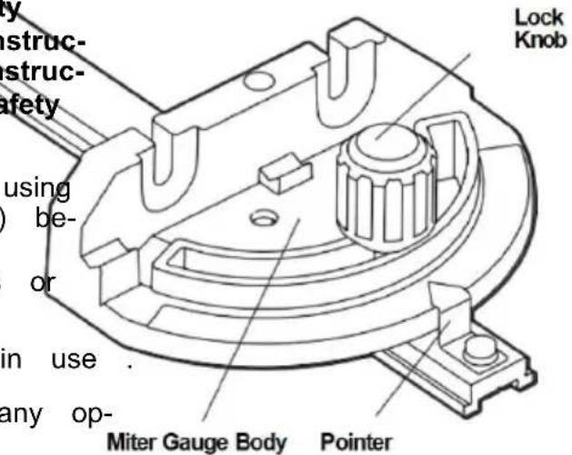
To adjust the miter angle:
Loosen lock knob and set the miter gauge body so that the pointer is at desired angle, then 3 tightening 3" lock knob (Fig . 53). Board
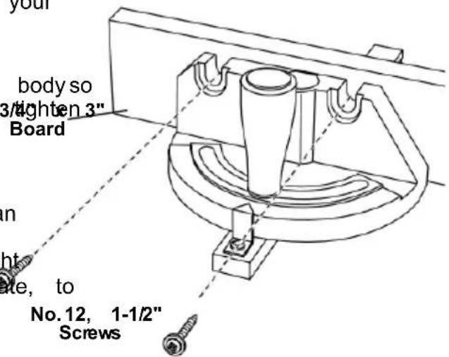
MITER GAUGE AUXILIARY FACING
The miter gauge is designed to accept an Auxiliary Facing with pre-molded holes for fastening a suitable piece of smooth straight wood. Utilize the miter gauge as a template, to attach with proper fasteners (Fig . 54) . No.1
Example:
A. Drill 5/32" dia. holes through a board 3/4" thick, 3" high, and desired length.
B . Attach with two No . 12 round head wood screws 1-1/2" long, not included (Fig . 54) .
Be sure that the screws never protrude above the outside surface of facing.
Be sure the facing does not interfere with the proper operation of the saw blade guard.
Basic Table Saw Operation
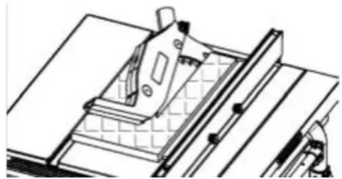
CROSSCUTTING
CROSSCUTTING is known as cutting wood across the grain, at 90°, or square with TIP. The space between the miter gauge be edge and the flat side of the wood. This is done in the table is held to a minir with the miter gauge set at 90° (Fig . 55). Manufacturing. For maximum accuracy when make sure that the blade guard is installed for all using the miter gauge, always "favor" one s "through sawing" operations (when the sawblade cuts entirely through the thickness of the work- piece). Replace guard IMMEDIATELY after completion of dadoing or rabbeting cuts. The groove.
Have the blade extend approximately 1/8" TIP: Glue a piece of sandpaper to the face top of workpiece. On Add blade exposure would miter gauge head. This will enhance the prwork-increase the hazard potential. piece from "creeping" while it is being cut
Do not stand directly in front of the blade in case of a THROWBACK (small cut-off piece caught by the back of the blade and thrown toward the blade) . Stand to either side of the blade. The miter gauge may be used in either of grooves in the table . Make sure it is loc Groove, hold the workpiece firmly against ga head with your left hand, and grip the lock with your right hand . Keep your hands clear of the blade and out of the path of the blade .
If the blade stalls or stops while cutting, TURN THE SWITCH OFF before attempting to free the workpiece with your right hand and the lock with your left hand.
Do not reach over or behind the blade to pull the workpiece through the ,cuto support long or heavy workpieces, to remove cut-off pieces of material, or FOR ANY OTHER REASON .
Do not pick up small pieces of cut-off material from the table. REMOVE them by pushing them OFF the table with a long stick. Otherwise they could be thrown back at you by the rear of the blade.
Do not remove small pieces of cut-off material that are close to or may become TRAPPED inside the blade guard while the saw is RUNNING. THIS COULD ENDANGER YOUR HANDS or cause a KICKBACK. Tume saw OFF. After the blade has stopped turning, lift the guard and remove the piece.
If the workpiece is warped, place the CONCAVE side DOWN. This will help to prevent it from a rocking while it is being cut.
The graduations on the miter gauge provide accuracy for average woodworking. In some cases where extreme accuracy is required, when making angle cuts, for example, make a trial cut and then recheck it with an accurate square or protractor.
Basic Table Saw Operation
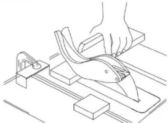
REPETITIVE CUTTING
REPETITIVE CUTTING is cutting a quantit pieces the same length without having to each piece (Fig . 56) .
When using the miter gauge in the LEFT groove, hold the workpiece firmly against the miter gauge head with your left hand, and lock knob with your right hand.
When making repetitive cuts from a long piece, make sure it is supported.
When using the RIGHT hand groove, hold the workpiece with your right hand and the lock with your left hand.

Never use the rip fence as a length stop, because the cut
FIG.5
off piece could bind between the fence and the blade causing a kickback.
- When making repetitive cuts, clamp a block of wood 3" long to the table at the desired length to act as a length stop.

When clamping the block, make sure that the end of
the block is well in front of the sawblade. Be sure that it is clamped securely.
- Slide the workpiece along the miter gauge until it touches the block, then hold it securely.
- Make the cut, pull the workpiece back. push the cut-off piece off the table with a push stick. DO NOT ATTEMPT TO PICK UP AS THIS COULD ENDANGER YOUR HANDS.
natural_image
Line drawing of a hand using a cutting tool on a workbench with blocks and tools (no text or symbols)FIG.
MITER CUTTING
MITER CUTTING is cutting wood at an angle other than 90^ with the edge of the wood.
the same procedure as you would for (Fig . 57) .
Adjust the miter gauge to the desired lock it.
The miter gauge may be used in either grooves in the table.
BEVEL CROSSCUTTING
BEVEL CROSSCUTTING is the same as cross-ack, then cutting except that the wood is also cut at with a long angle other than 90° with the flat side of PICK II (Fig . 58).
Adjust the blade to the desired angle.
Use the Miter Gauge in the groove to the or the LEFT of the blade.
FIG.5
natural_image
Technical line drawing of a mechanical assembly with no visible text or symbolsFellow COMPOUND MITER CUTTING
COMPOUND MITER CUTTING is a combination of miter cutting and bevel crosscutting angle, ischade at an angle other than 90° to the edge and the flat side of the wood.
Adjust the miter gauge and the blade to the desired angle and make sure that miter gauge is locked.
Basic Table Saw Operation
NON THROUGH SAWING
RABBETING
Add an 8" high flat facing board to the RABETINGe is cutting out a section of the full length of the fence (Fig . 59) . of a piece of material, across an end or
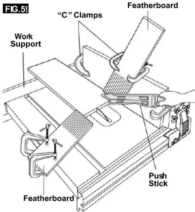
Making a RABBET requires cuts that do not the way through the material. Therefore, the Blade Guard must be removed.
- Remove blade guard.
-
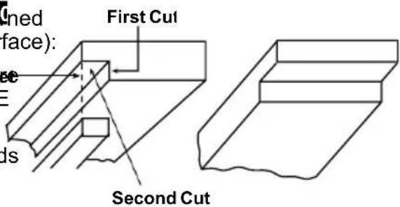
For rabbeting along an edge (long way workpiece) as shown, add a facing approximately as high as the workpiece is wide the rip fence. Adjust the rip fence and to the required dimensions, then make the first cut with the board flat on the table, lowing the set-up shown in Fig. 60. second cut with the workpiece on its edge Follow all precautions, safety instructions, and operation instructions as for ripping type operations, including featherboards and push stick, etc.
-
For rabbeting across an end, for workpiece 10-1/2" and narrower make the rabbet cut with board flat on the table. Using the miter fitted with a facing, follow the same procedures
Use featherboards for all "Non Through Sawing operations (when the sawblade guard must be removed). Featherboards are used to keep the work in contact with the fence and the table as shown, and to stop kickbacks.
- INSTALL Blade Guard IMMEDIATELY UPON COMPLETION OF RABBET-ING OPERATION. Mount featherboards to the fence and table as shown, so that the leading edges of the feathers boards will support the workpiece until the cut is
complete, and the workpiece has been pushed completely past the cutter (sawblade, dado head, etc.) with a push stick, as in ripping.
Before starting the operation (with the sat FIG.6(1) and "OFF" and the cutter set below the table surface):
A. Install featherboards so they exert prRabbe on the workpiece; BE POSITIVE THEY ARE SECURELY ATTACHED.
B. Make sure, by trial, that the featherboards will stop a kickback if one should occur.
Featherboards are not employed during non through sawing operations when using the miter gauge.
REPLACE THE Blade Guard AS SOON AS THE NON THROUGH SAWING OPERATION IS COMPLETE .
RABBETINGALON
THE EDGE
RABBETINGACROSS
THE END
Basic Table Saw Operation
SPECIAL
CUTTING TECHNIQUES
CUTTING
METALS AND MASONRY

Do not attempt to perform cuts not covered in this

This table saws not recommended for cutting metal aluminum or copper, even with
manual unless you are thoroughly familiar with procedures and fixturing. These types of cuts include, but are not limited to, tapered cuts and complex non-through cutting. This table saw is a highly versatile tool, capable of warning. This table saw is not commended for cutting any performing a wide range of highly specialized cuts that cannot be covered in the manual.
See your local library for books on woodworking techniques, such as: The Complete Book of Stationary Power TooTechniques by R .J . De Christoforo or Table Saw Techniques by R . Cliffe .
LUBRICATION
The gear case has been completely lubricated at the factory. However, after six months to one year, depending upon use, it's wise to return your tool to the nearest Service Center for the following:
- Brushes replaced .
- Parts cleaned and inspected .
- Relubricated with fresh lubricant.
• Electrical system tested. - All repairs .
The following parts should be oiled occasionally with SAE No. 20 or No. 30 oil, or WD 40
- Elevation, support rods, and gears.
- Sligin rails and supports.
- Table locking cams (Front & Rear).
Maintaining Your Table Saw
Danger!
Always pull out the mains power plug starting any cleaning work.
1. Cleaning
- Keep all safety devices, air vents and motor housing free of dirt and dust as as possible. Wipe the equipment with a cloth or blow it with compressed air at low pressure.
• We recommend that you clean the de immediately each time you have finished using it.
- Clean the equipment regularly with a cloth and some soft soap. Do not use cleaning agents or solvents; these could attack the plastic parts of the equipment. Ensure that no water can seep into the The ingress of water into an electric tool increases the risk of an electric sh
2. Carbon brushes
before case of excessive sparking, have the carbon brushes checked only by a qualified electrician.
Danger! The carbon brushes should not be replaced by anyone but a qualified electrician.
3. Maintenance
There are no parts inside the equipment tl require additional maintenance.
4. Ordering replacement parts:
Please quote the following data when hoisting replacement parts:
- Type of machine
• Article number of the machine
• Identification number of the machine - de Replacement part number of the part required
Troubleshooting
WARNING
Turnswitch“OFF”andalwaysremoveplugfromthepowersourcebeforetroubleshootin
| PROBLEM | CAUSE | SOLUTION |
| Saw willnotstart | Power cord isnot plugged in. Plug sawin. | |
| Fuseorcircuit breakertripped. Replace fuseorreset tripped circuit breaker. | ||
| Corddamaged. | HavecordreplacedbyanAuthorizedVEVOR ServiceCenter orServiceStation. | |
| Burned outswitch. | HaveswitchreplacedbyanAuthorizedVEVOR ServiceCenter orServiceStation. | |
| Bladedoesnotcomeuptospeed | Extension cordtoo lightor tooloReplace withadequatecord. | |
| Lowsupply voltage. | Contactyourelectric company. | |
| Excessive vibration | Failure totighten bevellockhandSee“Getting ToKnowYourTableSaw” section. | |
| Bladeout ofbalance. Discard Bladeanduse different blade. | ||
| Saw not mounted securelytoftighten all mounting hardware, See the Table Saw” section. | ||
| ArborNut not tight. | See“Assembly” section, “Changing The Blade | |
| Cutbinds,burns,stallsmotor whenripping | Dull blade with impropertooth set. Sharpenor replaceblade. | |
| Warpedboard. | Makesure concaveorhollow sideis facing “DOWN” and feed slowly. | |
| Ripfence not parallel toblade. | See “Adjustments” section “Aligning Rip Fence.” | |
| Riving knifeout ofalignment. | See “Adjustments” section,“Riving knife alignment.” | |
| Cutnottrueat90° or45°positions | Alignment screwsnot adjusted properly. | See“Adjustments” section, “Adjusting Blade Parallel to Miter Gauge Slots.” |
| Plasticmeltsorbladetipsoverheatwhen cutting | Feedrate to high. | Slow feedratethroughblade. |
| Blades tip not sharp Sharpenor replaceblade | ||
| Tiltlockhandle elevation wheel hard tomove | Bevellockhandlenotloosenedwhen making tilt adjustment. | See“GettingToKnowYourTableSaw” section, “Blade Tilt Lock Knob.” |
| Sawdustondepthscrew threads. | See “Maintaining Your Table Saw” section, “Lubrication.” | |
| CircuitBreaker Trips | Circuit breaker trips repeatedlyReplace the blade with a new blade. Red force applied to workpiece during cutting. | |
TECHNICALDATA
AC Motor 120V\~60Hz (220-240\~50Hz)
Rated Current....15A (1800W)
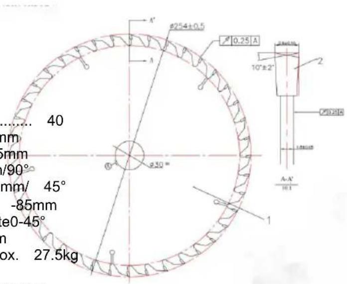
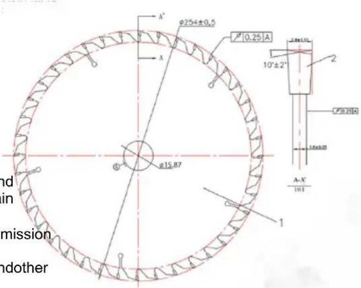
Cutting-OffWheel....Ø254xØ15.875x2.8mm .... (Ø 254 x Ø30mm)
Idle Speed 5000 RPM (4800RPM)
NumberOfTeeth.... 40
MainTableSize....650x576mm
RipCapacityForRight....625mm
CuttingHeightMax....85mm/90° .....55mm/ 45°
HeightAdjustment......Infinite0 -85mm
TiltingSawBlade......Infinite0-45°
ExtractorSocket....Ø 35mm
Weight.....Approx. 27.5kg
Operating modeS625%:Continuousoperationwithidling (cycletime10minutes).
Toensurethatthemotordoesnotbecomeexcessively
hot, it may only beoperated
for25%ofthecycleatthespecifiedratingandmustthen
beallowedtoidlefor75%
ofthecycle.
Danger!
Soundandvibration
Soundandvibrationvaluesweremeasuredin
accordancewithEN 61029.
LpAsoundpressure level....91dB(A)
KpAuncertainty....3 dB
LWAsoundpowerlevel.... 104dB(A)
KWAuncertainty....3 dB
Thequotedvaluesareemissionvaluesandnot necessarilyreliable workplacevalues.
Although thereisa correlation between emission and immission levelsit is impossible to draw any certain conclusions as totheneed for additional prescauti
Factorswith a potentialinfluence on theactualimmission levelattheworkplace
includethedurationof impact,thetypeof room,andother sourcesofnoise,etc.,
e.g.thenumberofmachinesandotherneighboring operations.Reliableworkplace
valuesmayalsovaryfromcountrytocountry.Withthis information,theusershould
atleastbeable tomakea betterassessmentofthe dangersand risksinvolved.
VEVOR®
TOUGH TOOLS, HALF PRICE
Technical Support and E-Warranty Certificate
www.vevor.com/support
VEVOR®
TOUGH TOOLS, HALF PRICE
natural_image
3D rendering of a metal cutting machine with wheels and cutouts (no text or symbols visible)BESOIN D'AIDE? CONTACTEZ-NOUS!
natural_image
Electrical outlet diagram showing a 120-pin socket connected to a wire (no text or symbols)natural_image
Icon of a person wearing glasses inside a circle (no text or symbols)
support 13. Support pliable
natural_image
Close-up of a mechanical component or tool with no visible text or symbols


Assemblée
Figure B
ÉTAPE 1
Figure E

natural_image
Diagram of a mechanical device with two circular insets highlighting internal components (no text or symbols)Figure F

Figure G
Figure H


Figure I
Assemblée
ÉTAPE 7
natural_image
Line drawing of a mechanical component with a wheel and bolts, no text or symbols presentFigure J
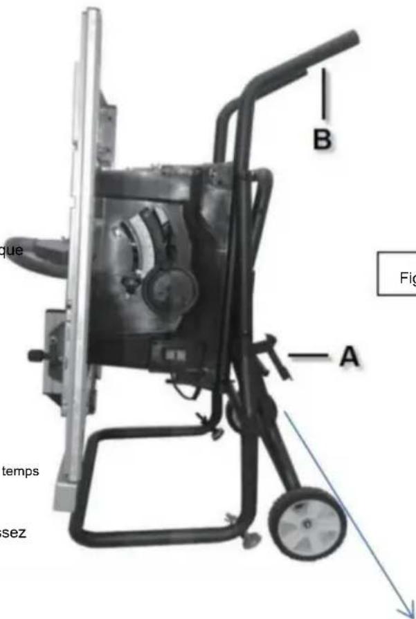
Figure K
natural_image
Close-up of a metal frame structure with no visible text or symbolsAssemblée
FIXATION DU PROTECTEUR DE LAME
AVERTISSEMENT
natural_image
Pure technical diagram of a mechanical component with labeled parts (no text or symbols beyond 'A')natural_image
Two-step diagram showing hand tool application on a cutting board, with numbered arrows indicating steps (no text or symbols present)FIG.6

natural_image
Close-up of a mechanical component with a white arrow pointing to a specific part (no visible text or symbols)FIG.7

Assemblée
FIXATION DE L'ENSEMBLE DE PROTECTION
Machine Translated by Google
natural_image
Mechanical assembly with a metal frame and labeled component A (no text or symbols beyond label)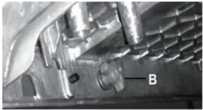
natural_image
Close-up of a metallic mechanical component with internal cavities and a labeled feature 'B' (no readable text or symbols beyond label)Ajustements
natural_image
Diagram of a mechanical gear system with labeled component A, showing toothed circular components and a rotating shaft (no text or symbols beyond label)
natural_image
Diagram of a gear and blade assembly with labeled component B (no text or symbols present)FIG.42


AIDES AU TRAVAIL
natural_image
Technical line drawing of a mechanical clamp or bracket assembly (no text or symbols)natural_image
Line drawing of a mechanical assembly with hands operating a workpiece (no text or symbols)DÉCHIRURE EN BISEAU
natural_image
Technical line drawing of a mechanical assembly with grid-patterned components and labeled parts (no readable text or symbols)natural_image
Line drawing of hands using a tool to cut or spread materials on a cutting board (no text or symbols)FIG.55
natural_image
Technical line drawing of a mechanical assembly with a hand operating a tool (no text or symbols visible)TRONÇONNEUSE EN BISEAU
natural_image
Line drawing of a hand using a tool to cut or spread a piece of paper into a block, with no text or symbols present.FIG.56
COUPE À ONGLET
natural_image
Technical line drawing of a mechanical assembly with no visible text or symbolsMachine Translated by Google
DONNÉES TECHNIQUES
VEVOR®
TOUGH TOOLS, HALF PRICE
natural_image
3D rendering of a metal cutting machine with wheels and cutouts (no text or symbols visible)natural_image
Simple line drawing of a wall-mounted electrical outlet with a cable plugged into (no text or symbols)natural_image
Icon of a person wearing glasses inside a circle (no text or symbols)
natural_image
Close-up of a mechanical component or tool with no visible text or symbols


E.M6*55mm Schraube *2
Montage
Abbildung B
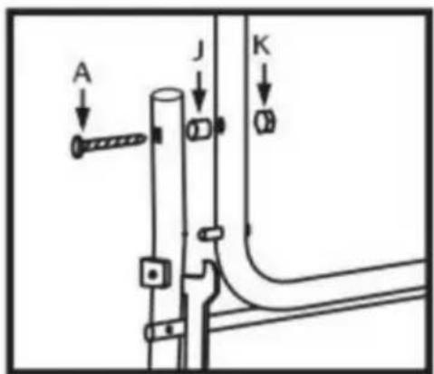
Abbildung C
SCHRITT3
Abbildung E

natural_image
Diagram of a mechanical device with two circular insets highlighting internal components (no text or symbols)Abbildung F

Abbildung G
Abbildung H
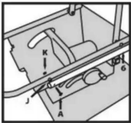

Abbildung I
Montage
SCHRITT7
natural_image
Line drawing of a mechanical component with rollers and bolts (no text or symbols)Abbildung J
natural_image
Close-up of a metal frame structure with no visible text or symbolsMontage
natural_image
Pure technical diagram of a mechanical component with labeled parts (no text or symbols)Spaltkeil

natural_image
Two-step diagram showing hand tool application on a cutting board, with arrows indicating rotation (no text or symbols)Abb. 6

natural_image
Close-up of a mechanical component with a metallic blade and a white arrow pointing to a feature (no visible text or symbols)Abb.7

Montage
Machine Translated by Google

Anpassungen
natural_image
Mechanical assembly with a rectangular component labeled 'A' and a roller roller (no text or symbols beyond label)
natural_image
Close-up of a metallic mechanical component with internal cavities and a labeled feature 'B' (no readable text or symbols beyond label)Anpassungen
natural_image
Diagram of a mechanical gear system with a rotating wheel and guide mechanism (no text or labels)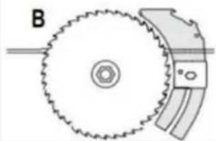
natural_image
Diagram of a gear and blade assembly with labeled component B (no text or symbols present)Abb.42

natural_image
Technical line drawing of a mechanical component with no visible text or symbolsnatural_image
Line drawing of a mechanical setup with hands operating a workbench and a curved component (no text or symbols)
natural_image
Technical line drawing of a mechanical assembly with grid-patterned components and labeled parts (no readable text or symbols)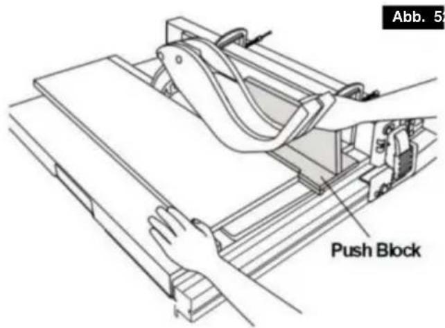
natural_image
Line drawing of hands using a tool to cut or spread a piece of material on a cutting board (no text or symbols)Abb. 59
natural_image
Line drawing of a hand using a tool to cut a piece of paper into a block, with no visible text or symbols.Abb. 5
Gehrungsschnitt
natural_image
Technical line drawing of a mechanical assembly with a hand operating a tool (no text or symbols visible)FASENKREISSCHNITT
natural_image
Technical line drawing of a mechanical assembly with no visible text or symbolsGehrungsschnitt
Machine Translated by Google
TECHNISCHE DATEN
Wechselstrommotor.....120 V\~60 Hz (220-240\~50 Hz)

VEVOR®
TOUGH TOOLS, HALF PRICE
natural_image
3D rendering of a metal cutting machine with wheels and cutouts (no text or symbols visible)Laboratories e la Canadian
Standards Association. II
natural_image
Icon of a person wearing glasses inside a circle (no text or symbols)
natural_image
Close-up of a mechanical component or tool with no visible text or symbols


Assemblea
Figura B
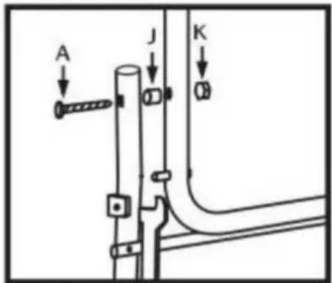
Figura C
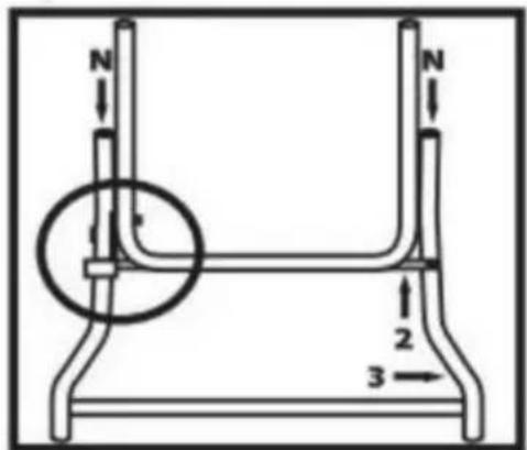
Figura D
Assemblea
FASE 4
Figura E

natural_image
Diagram of a mechanical device with two circular insets highlighting internal components (no text or symbols)Figura F

Figura G
Figura H

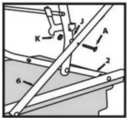
Figura I
Assemblea
PASSO 7
natural_image
Line drawing of a mechanical component with rollers and bolts (no text or symbols)Figura J
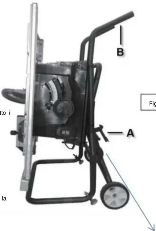
Figura K

natural_image
Close-up of a metal frame structure with no visible text or symbolsAssemblea
natural_image
Pure diagram of a container with wheels and a labeled section A, no text or symbols presentnatural_image
Two-step diagram showing hand tool application on a cutting board, with numbered arrows indicating steps (no text or symbols present)FIGURA6
natural_image
Close-up of a mechanical component with a white arrow pointing to a specific part (no visible text or symbols)FIGURA 7

Assemblea
Machine Translated by Google
Regolazioni
natural_image
Mechanical assembly with a rectangular component labeled 'A' and a roller roller (no text or symbols beyond label)
natural_image
Close-up of a metallic mechanical component with internal cavities and a labeled feature 'B' (no readable text or symbols beyond label)Regolazioni
natural_image
Diagram of a mechanical gear system with a rotating wheel and guide mechanism (no text or labels)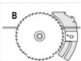
natural_image
Diagram of a mechanical gear assembly with labeled component B (no text or symbols beyond label)FIGURA42
natural_image
Technical line drawing of a mechanical clamp or bracket assembly (no text or symbols)natural_image
Technical line drawing of a mechanical assembly with levers and clamps (no text or symbols)natural_image
Technical line drawing of a mechanical assembly with grid-patterned panel and support brackets (no text or symbols)natural_image
Line drawing of hands using a tool to cut or spread materials on a cutting board (no text or symbols)FIGURA55
natural_image
Line drawing of a hand using a pliers to cut or lift a block on a cutting board (no text or symbols)TAGLIO A QUADRETTI
natural_image
Technical line drawing of a mechanical assembly with no visible text or symbolsMachine Translated by Google
DATI TECNICI
AcMotor.....120v\~60Hz (220-240\~50Hz)

VEVOR®
TOUGH TOOLS, HALF PRICE
natural_image
3D rendering of a metal cutting machine with wheels and cutouts (no text or symbols visible)natural_image
Electrical outlet diagram showing a 20-pin socket connected to a wire (no text or symbols)natural_image
Icon of a person wearing glasses inside a circle (no text or symbols)
natural_image
Close-up of a mechanical component or tool with no visible text or symbols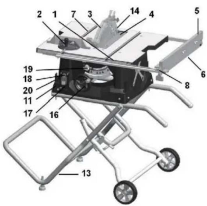

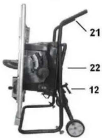
Asamblea
Figura B

Figura C

Figura D
Asamblea
PASO 4
Figura E
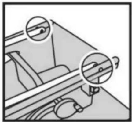
natural_image
Diagram of a mechanical device with two circular insets highlighting internal components (no text or symbols)Figura F
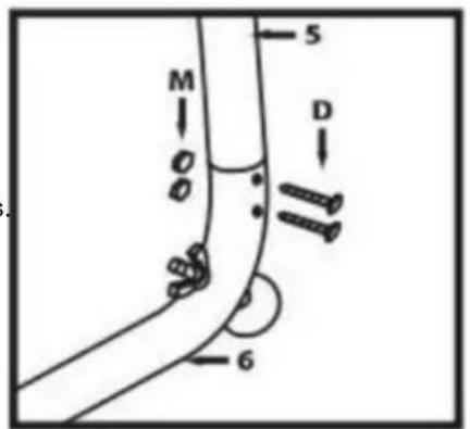
Figura G
Figura H


Figura I
Asamblea
PASO 7
natural_image
Line drawing of a mechanical component with rollers and bolts (no text or symbols)Figura J
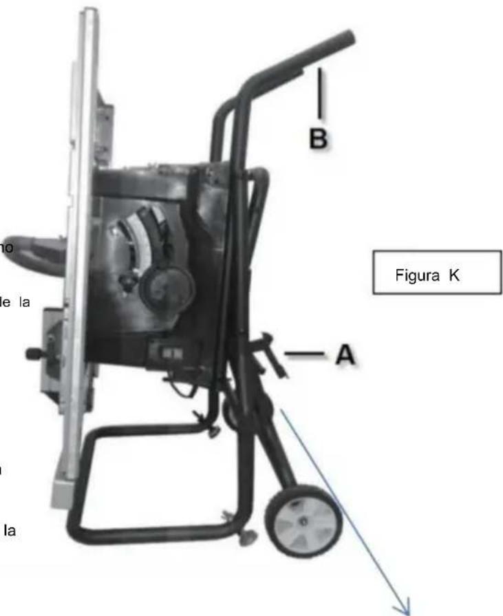

natural_image
Close-up of a metal bracket with visible joints and structural details (no text or symbols)Asamblea
natural_image
Pure diagram of a container with wheels and a labeled section A, no text or symbols presentFigura 5
Cuchillo divisor

natural_image
Two-step diagram showing hand tool application on a cutting board, with numbered arrows indicating steps (no text or symbols present)Figura 6

natural_image
Close-up of a mechanical component with a white arrow pointing to a specific part (no visible text or symbols)Figura 7

Asamblea
Machine Translated by Google

Ajustes
Ajuste de la mesa extensible (Fig. 9 y Fig. 10)
natural_image
Mechanical assembly with a labeled component 'A' on a metal frame (no text or symbols beyond label)
natural_image
Close-up of a metallic mechanical component with internal cavities and a labeled feature 'B' (no readable text or symbols beyond label)Ajustes
natural_image
Diagram of a mechanical gear system with labeled section A, showing toothed circular components and a rotating shaft (no text or symbols beyond label)
natural_image
Diagram of a gear and blade assembly with labeled component B (no text or symbols present)Figura 4

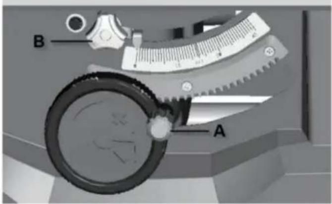
natural_image
Technical line drawing of a mechanical clamp or bracket assembly (no text or symbols)natural_image
Line drawing of a mechanical assembly with hands operating a workpiece (no text or symbols)CORTE EN BISEL
natural_image
Technical line drawing of a mechanical assembly with grid-patterned components and labeled parts (no readable text or symbols)natural_image
Line drawing of hands using a tool to cut or spread materials on a cutting board (no text or symbols)Figura 55
natural_image
Technical line drawing of a mechanical assembly with a hand operating a tool, no visible text or symbolsCORTE TRANSVERSAL BISELADO
natural_image
Line drawing of a hand using a tool to cut a piece of material, with no visible text or symbolsFigura 56
CORTE A INGLETE
natural_image
Technical line drawing of a mechanical assembly with no visible text or symbolsCORTE DE INGLETE COMPUESTO
Machine Translated by Google
DATOS TÉCNICOS Motor
Ac.....120v\~60Hz (220-240\~50Hz)
Corriente nominal 15 A (1800 W) Disco de
corte ..... 254 x 15,875 x 2,8 mm .....
( 254 x 30 mm)

VEVOR®
TOUGH TOOLS, HALF PRICE
natural_image
3D rendering of a metal cutting machine with wheels and cutouts (no text or symbols visible)POTRZEBUJESZ POMOCY? SKONTAKTUJ SIĘ Z NAMI!
natural_image
Illustration of a wall-mounted electrical outlet with a separate plug shown alongside (no text or symbols)natural_image
Icon of a person wearing glasses inside a circle (no text or symbols)
natural_image
Close-up of a mechanical component or tool with no visible text or symbols


Rysunek B

Rysunek C
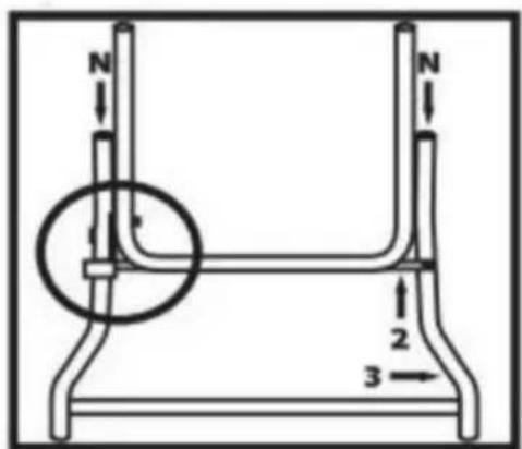
Rysunek D
Montaż
KROK 4
Rysunek E

natural_image
Diagram of a mechanical device with two circular insets highlighting internal components (no text or symbols)Rysunek F

Rysunek G
Rysunek H

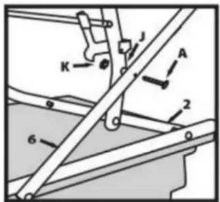
Rysunek I
Montaż
KROK 7
natural_image
Line drawing of a mechanical component with rollers and bolts (no text or symbols)Rysunek J
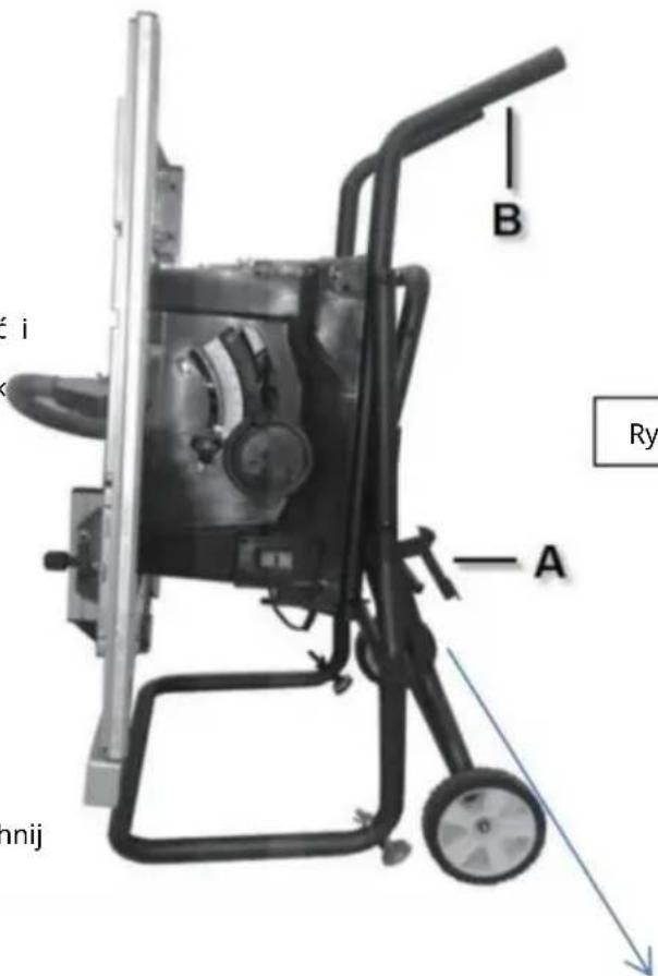
Rysunek K
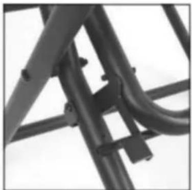
natural_image
Close-up of a metal bracket with visible joints and structural details (no text or symbols)Montaż
natural_image
Pure diagram of a container with wheels and a labeled section A, no text or symbols presentRys.5
Nóż rozdzielający
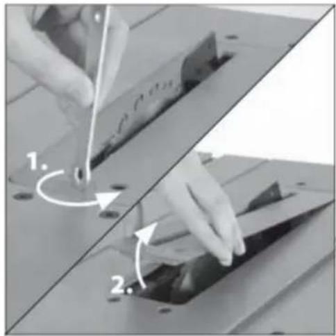
natural_image
Two-step diagram showing hand turning a component on a cutting board, with arrows indicating rotation (no text or symbols)Rys.6
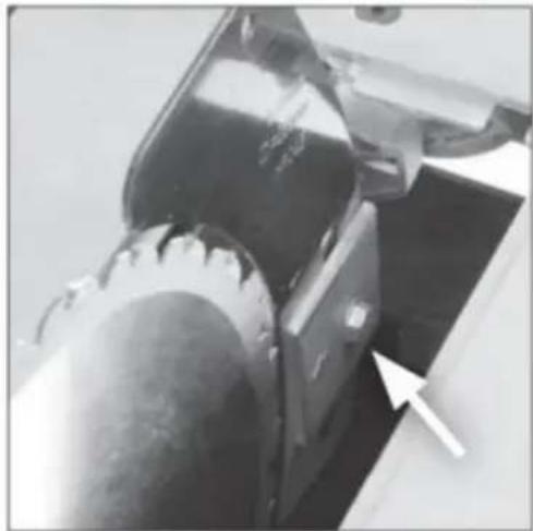
natural_image
Close-up of a mechanical component with a white arrow pointing to a specific part (no visible text or symbols)Rys.7
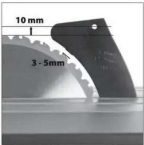
Montaż
MONTAŻ ZESTAWU OSŁON
Machine Translated by Google
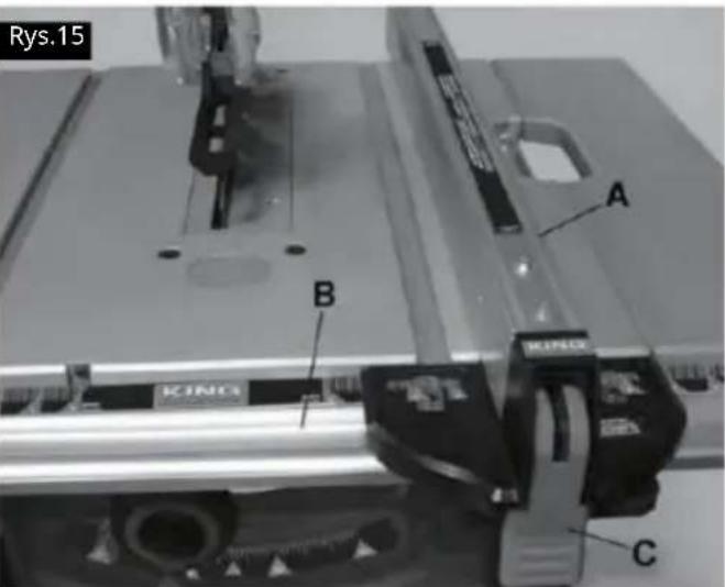
Dostosowania
natural_image
Mechanical assembly with a rectangular component labeled 'A' and a roller roller (no text or symbols beyond label)
natural_image
Close-up of a metallic mechanical component with internal cavities and a labeled feature 'B' (no readable text or symbols beyond label)Dostosowania
natural_image
Diagram of a mechanical gear system with a rotating wheel and guide mechanism (no text or labels)
natural_image
Diagram of a gear and cam mechanism with labeled component B (no text or symbols beyond label)Rys.42


natural_image
Line drawing of a mechanical assembly with hands operating a workpiece (no text or symbols)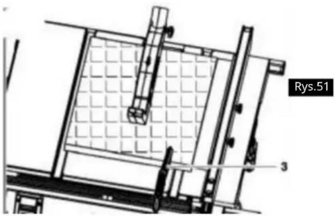
natural_image
Technical line drawing of a mechanical assembly with grid-patterned components and labeled part 'Rys.51' (no readable text or symbols beyond label)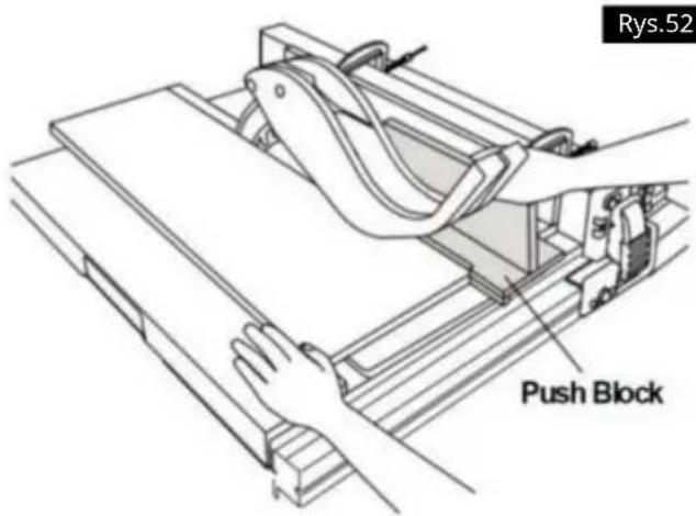
natural_image
Line drawing of hands using a tool to cut or spread a piece of material on a cutting board (no text or symbols)Rys.55
natural_image
Line drawing of a hand using a tool to cut or spread material on a flat surface, with no text or symbols present.Rys.56
CIECIE POD KATEM
natural_image
Technical line drawing of a mechanical assembly with a hand operating a tool (no text or symbols visible)CIĘCIE POPRZECZNE SKOŚNE
natural_image
Technical line drawing of a mechanical assembly with no visible text or symbolsCIĘCIE METALI I MURARSTWO

Machine Translated by Google
DANE TECHNICZNE Silnik

VEVOR®
TOUGH TOOLS, HALF PRICE
natural_image
3D rendering of a metal cutting machine with wheels and cutouts (no text or symbols visible)HULP NODIG? NEEM CONTACT MET ONS OP!
BEWAAR ALLE WAARSCHUWINGEN EN INSTRUCTIES VOOR TOEKOMSTIGE REFERENTIE.
WAARSCHUWINGEN MET BETREKKING TOT BEWAKING
natural_image
Simple line drawing of a wall-mounted electrical outlet with a cable plugged into (no text or symbols)natural_image
Icon of a person wearing glasses inside a circle (no text or symbols)
natural_image
Close-up of a mechanical component or tool with no visible text or symbols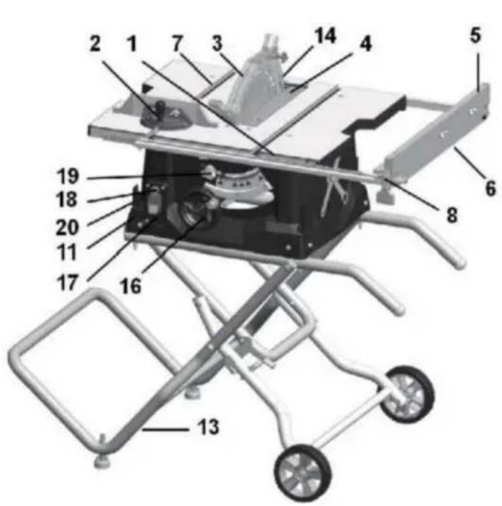
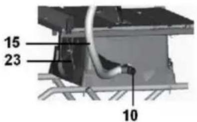
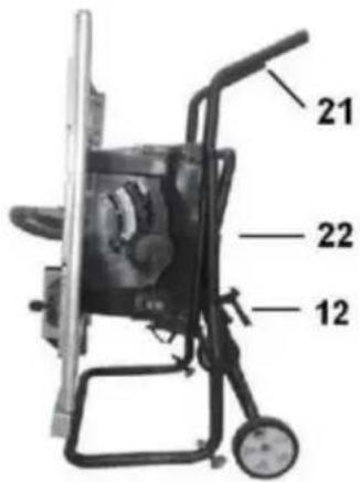
B.M6*75mm schroef *4
C.M5*50mm schroef *2
D.M5*40mm schroef *4
E.M6*55mm schroef *2
F.M5*10mm schroef *1
Montage
Figuur B

Figuur C

Figuur D
Montage
STAP 4
Figuur E

natural_image
Diagram of a mechanical device with two circular insets highlighting internal components (no text or symbols)Figuur F
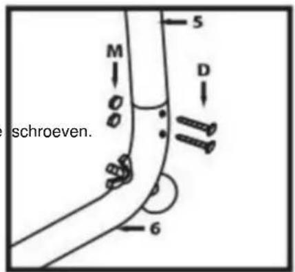
Figuur G
Figuur H


Figuur I
Montage
STAP 7
natural_image
Line drawing of a mechanical component with rollers and bolts (no text or symbols)Figuur J
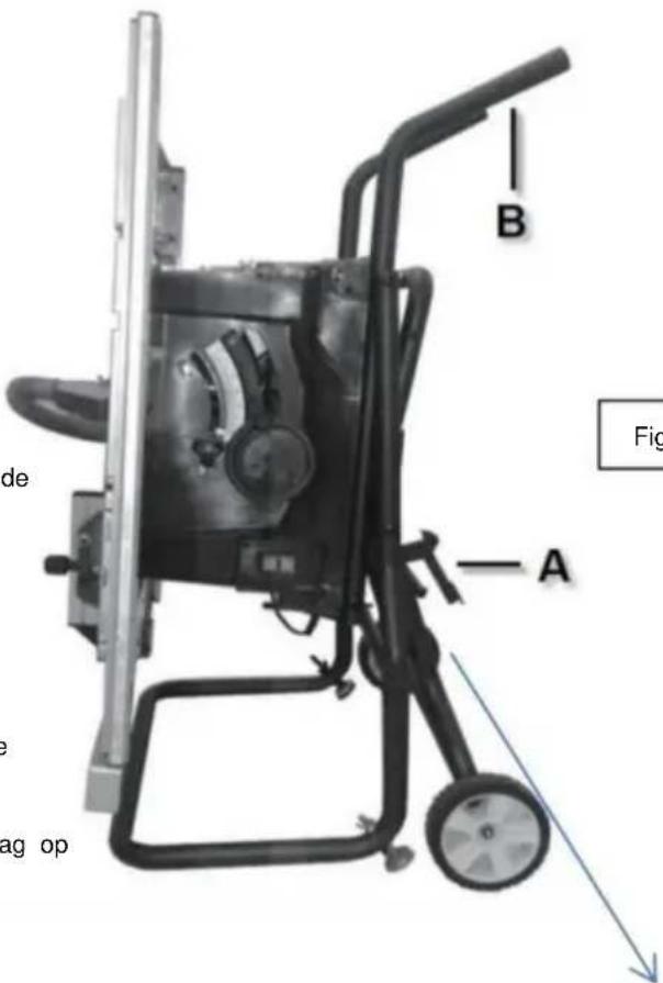
Figuur K

natural_image
Close-up of a metal bracket with visible joints and structural details (no text or symbols)Montage
BEVESTIGEN VAN DE MESBESCHERMING
WAARSCHUWING
natural_image
Pure diagram of a container with wheels and a labeled section A, no text or symbols presentFIG.5
Kloofmes

natural_image
Two-step diagram showing hand tool application on a cutting board, with numbered arrows indicating steps (no text or symbols present)AFBEELDING 8
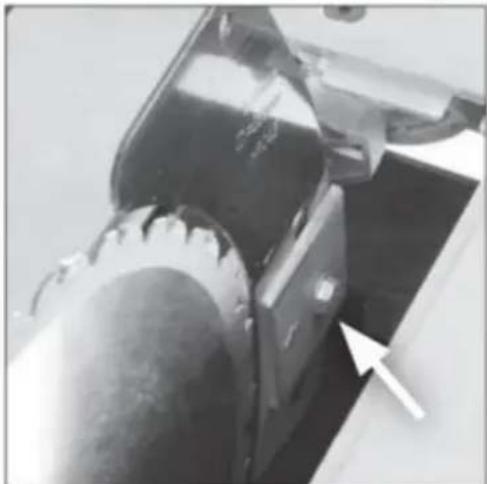
natural_image
Close-up of a mechanical component with a white arrow pointing to a curved feature (no visible text or symbols)AFBEELDING.7

Montage
BEVESTIGEN VAN DE BESCHERMINGSEENHEID
WAARSCHUWING: De machine moet
losgekoppeld van de
Machine Translated by Google
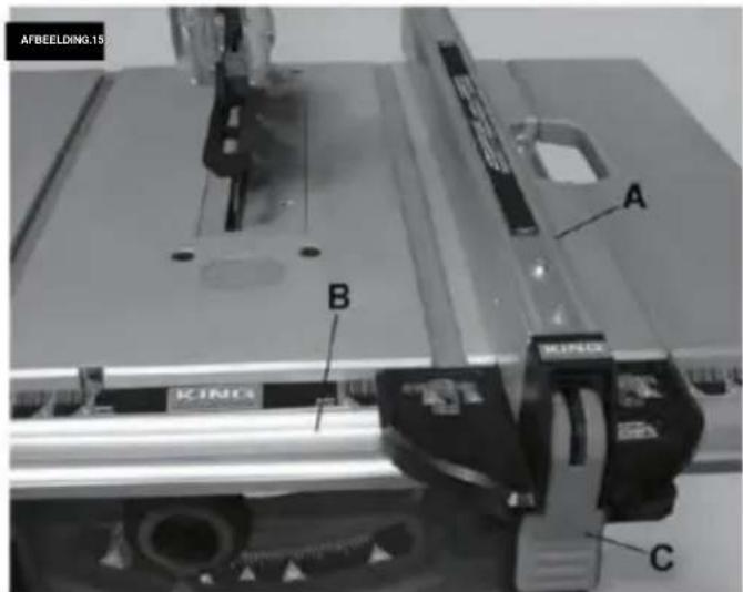
Aanpassingen
natural_image
Mechanical assembly with a rectangular component labeled 'A' and a roller roller (no text or symbols beyond label)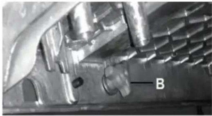
natural_image
Close-up of a metallic mechanical component with internal cavities and a labeled feature 'B' (no readable text or symbols beyond label)Aanpassingen
natural_image
Diagram of a mechanical gear system with a rotating wheel and guide mechanism (no text or labels)
natural_image
Diagram of a gear and blade assembly with labeled component B (no text or symbols present)

SCHEUREN, AFSCHUINEN, HERZAGEN EN
RIP FENCE HULPBESCHERMING
natural_image
Technical line drawing of a mechanical clamp or bracket assembly (no text or symbols)natural_image
Technical line drawing of a mechanical assembly with clamps and a wooden frame (no text or symbols)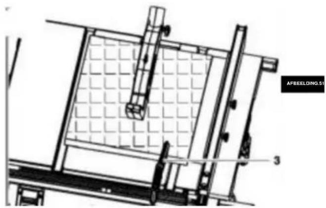
natural_image
Technical line drawing of a mechanical assembly with grid-patterned components and labeled part 'AFBEELDING.01' (no readable text or symbols beyond label)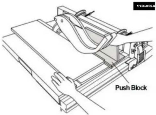
natural_image
Line drawing of hands using a tool to cut or spread materials on a cutting board (no text or symbols)FIG.55
natural_image
Line drawing of a hand using a pliers to cut or spread materials on a cutting board (no text or symbols)VERSTEK ZAGEN
natural_image
Technical line drawing of a mechanical assembly with no visible text or symbolsMachine Translated by Google
TECHNISCHE
GEGEVENS ACMotor.....120v\~60Hz (220-240\~50Hz)
Nominale stroom 15A (1800w) doorslijpen
van wiel I .....ÿ254xÿ15.875x2.8mm .....
(ÿ254xÿ30mm)
Stationair toerental 5000RPM (4800RPM)
Aantal tanden 40

VEVOR®
TOUGH TOOLS, HALF PRICE
Technische ondersteuning en E-garantiecertificaat www.vevor.comlsupport
VEVOR®
TOUGH TOOLS, HALF PRICE
www.vevor.com/support
BORDSÅG ANVÄNDARHANDBOK
MODELL:M1H-ZP5-254D-1
natural_image
3D rendering of a metal cutting machine with wheels and cutouts (no text or symbols visible)BEHÖVER HJÄLP? KONTAKTA OSS!
natural_image
Simple line drawing of a wall-mounted electrical outlet with a cable plugged into (no text or symbols)natural_image
Icon of a person wearing glasses inside a circle (no text or symbols)
natural_image
Close-up of a mechanical component or tool with no visible text or symbols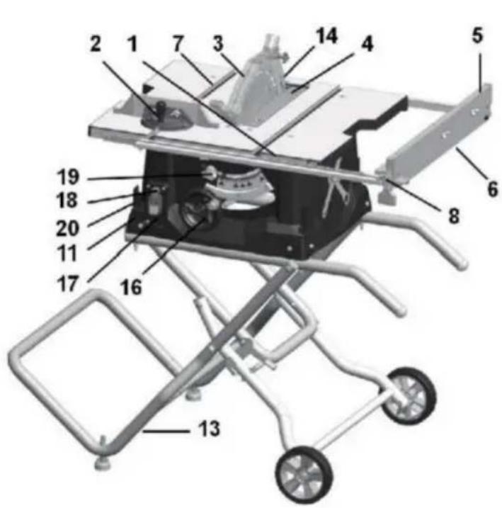


Montering
Bild B

Bild C

Bild D
Montering
STEG4
Bild E

natural_image
Diagram of a mechanical device with two circular insets highlighting internal components (no text or symbols)Bild F
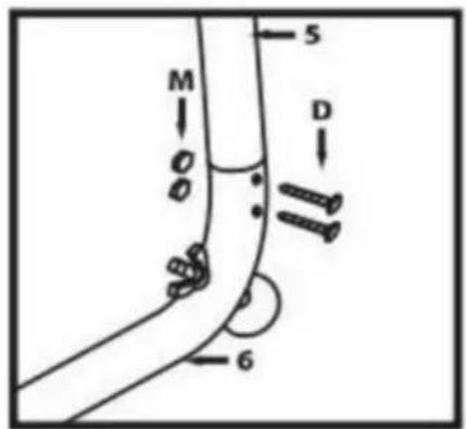
Bild G
Bild H
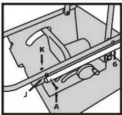

Figur I
Montering
STEG 7
natural_image
Close-up of a metal bracket with visible bolts and joints (no text or symbols)Montering
ATT FÄSTA STYRKET
WARNING
natural_image
Pure diagram of a container with wheels and a labeled section A, no text or symbols presentFIG.5
Klyvkniv
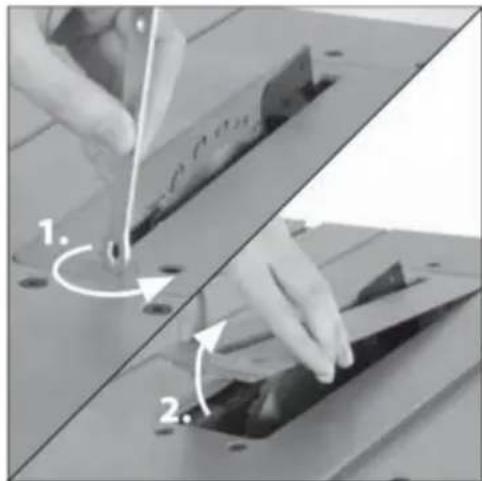
natural_image
Two-step diagram showing hand tool application on a cutting board, with numbered arrows indicating steps (no text or symbols present)FIG.6

natural_image
Close-up of a mechanical component with a white arrow pointing to a curved feature (no visible text or symbols)FIG.7

Montering
FÄSTNING AV SKYDDMONTAGET
Machine Translated by Google
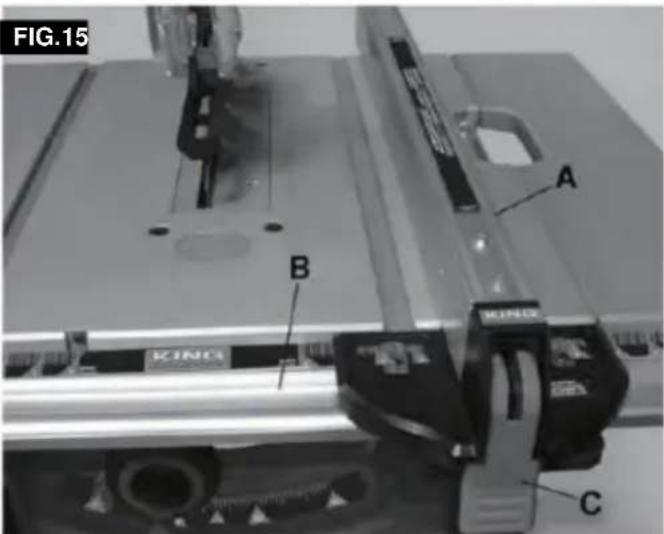
Justeringar
natural_image
Mechanical assembly with a labeled component 'A' on a metal frame (no text or symbols beyond label)
natural_image
Close-up of a metallic mechanical component with internal cavities and a labeled feature 'B' (no readable text or symbols beyond label)Justeringar
natural_image
Diagram of a mechanical gear system with a rotating wheel and guide mechanism (no text or labels)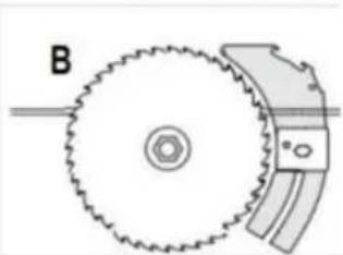
natural_image
Diagram of a gear and cam mechanism with labeled component B (no text or symbols beyond label)FIG.42

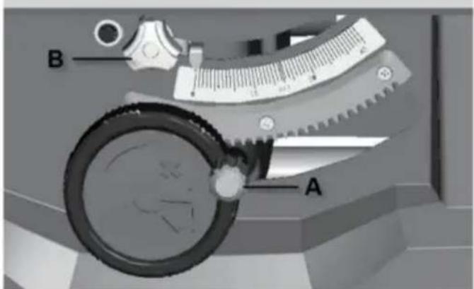
natural_image
Technical line drawing of a mechanical clamp or bracket assembly (no text or symbols)natural_image
Technical line drawing of a mechanical assembly with levers and clamps (no text or symbols)FAS RIPPNING
natural_image
Technical line drawing of a mechanical assembly with grid-patterned components and labeled parts (no readable text or symbols)FIG. 5
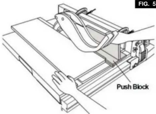
FIG. 52
natural_image
Line drawing of hands using a tool to cut or spread a piece of material on a cutting board (no text or symbols)FIG. 55
natural_image
Line drawing of a hand using a tool to cut a piece of material on a cutting board (no text or symbols)FIG. 5
GERINGSKÄRNING
natural_image
Technical line drawing of a mechanical assembly with a hand operating a tool (no text or symbols visible)AVFANSNING
natural_image
Technical line drawing of a mechanical assembly with no visible text or symbolsSAMMANSTÄLLD GERINGSKÄRNING
Idlespeed 5000RPM (4800RPM)
Antal tänder 40
MainTablesize 650x576mm

VEVOR®
TOUGH TOOLS, HALF PRICE