SBC220BF - Industrial machine Vevor - Free user manual and instructions
Find the device manual for free SBC220BF Vevor in PDF.

| Product Type | Pneumatic Blast Cabinet |
| Brand | Vevor |
| Model | SBC220BF |
| Working Area (L×W×H) | 828 mm × 542 mm × 548 mm |
| Viewing Window (L×H) | 570 mm × 26.5 mm |
| Abrasive Capacity | 40 lb (≈ 18 kg) |
| Included Nozzles | 4.5 mm, 5 mm, 6 mm, 7 mm |
| Average Air Consumption | 9.5 CFM at 90 PSI |
| Operating Pressure | 40 – 120 PSI (≈ 2.8 – 8.3 bar) |
| Recommended Compressor | 5 HP for optimal results, 3 HP minimum |
| Electrical Supply (Lamp) | Built-in transformer, 24V LED lamp |
| Chassis Material | Steel sheet with anti-rust coating |
| Included Gloves | 1 pair of abrasion-resistant gloves |
| Blast Gun | Included with nozzle and air connector |
| Recovery System | Built-in funnel, possibility to add a dust collector |
| Safety | Mandatory glove use, safety glasses, hearing protection |
| Maintenance | Regularly check seals, clean the window, drain compressor moisture |
| Repairability | Spare parts available: nozzles, gloves, seals, gun, hoses, etc. |
| Certifications | Compliant with FCC Part 15, WEEE Directive 2012/19/EU |
| Warranty | Electronic warranty certificate at www.vevor.com/support |
Frequently Asked Questions - SBC220BF Vevor
User questions about SBC220BF Vevor
0 question about this device. Answer the ones you know or ask your own.
Ask a new question about this device
Download the instructions for your Industrial machine in PDF format for free! Find your manual SBC220BF - Vevor and take your electronic device back in hand. On this page are published all the documents necessary for the use of your device. SBC220BF by Vevor.
USER MANUAL SBC220BF Vevor
C/O YH Consulting Limited Bureau 147,
Maison Centurion, London Road,
Staines-upon-Thames, Surrey, TW18 4AX

E-CrossStu GmbH.
Mainzer Landstr.69, 60329 Francfort-sur-le-Man.
VEVOR
TOUGH TOOLS, HALF PRICE
C/O YH Consulting Limited Office 147,
Centurion House, London Road,
Staines-upon-Thames, Surrey, TW18 4AX

E-CrossStu GmbH.
Mainzer Landstr.69, 60329 Frankfurt am Main.
VEVOR
TOUGH TOOLS, HALF PRICE
Casa Centurion, London Road,
Staines upon Thames, Surrey, TW18 4AX

E-CrossStu GmbH.
Mainzer Landstr.69, 60329 Francfort del Meno.
VEVOR
TOUGH TOOLS, HALF PRICE
Soporte专业技术o y certificate de garantia
electrónica www.vevor.com/support
VEVOR
TOUGH TOOLS, HALF PRICE
Importato in AUS: SIHAO PTY LTD. 1 ROKEVA STREETEASTWOOD NSW 2122Australia
C/O YH Consulting Limited Ufficio 147,
Casa del Centurione, London Road,
Staines-upon-Thames, Surrey, TW18 4AX

E-CrossStu GmbH.
Mainzer Landstr.69, 60329 Francoforte sul Meno.
VEVOR
TOUGH TOOLS, HALF PRICE
elettronica www.vevor.com/support
VEVOR®
TOUGH TOOLS, HALF PRICE
C/O YH Consulting Limited Biuro 147,
Dom Centuriona, London Road,
Staines-upon-Thames, Surrey, TW18 4AX

E-CrossStu GmbH.
Mainzer Landstr.69, 60329 Frankfurt nad Menem.
VEVOR
TOUGH TOOLS, HALF PRICE
www.vevor.com/support
VEVOR
TOUGH TOOLS, HALF PRICE
Technische ondersteuning en e-garantiecertificaat www.vevor.com/support
ZANDSTRALKAST MODEL:SBC220BF
HULP NODIG? NEEM CONTACT MET ONS OP!
VEILIGHEIDSWAARSCHUWING EN VOORZORGSGMAATREGELEN

Stap 4 Monteer de poot

C/O YH Consulting Limited Kantoor 147,
Centurion House, London Road,
Staines-upon-Thames, Surrey, TW18 4AX

E-CrossStu GmbH.
Mainzer Landstr.69, 60329 Frankfurt am Main.
VEVOR
TOUGH TOOLS, HALF PRICE
Technische ondersteuning en e-garantiecertificaat www.vevor.com/support
VEVOR
TOUGH TOOLS, HALF PRICE
C/O YH Consulting Limited Office 147,
Centurion House, London Road,
Staines-upon-Thames, Surrey, TW18 4AX

E-CrossStu GmbH.
Mainzer Landstr.69, 60329 Frankfurt am Main.
VEVOR
TOUGH TOOLS, HALF PRICE
www.vevor.com/support
VEVOR®
TOUGH TOOLS, HALF PRICE
Technical Support and E-Warranty Certificate www.vevor.com/support
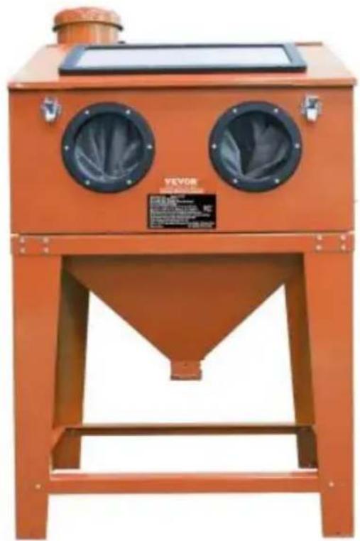
SAND BLASTER CABINET MODEL:SBC220BF
We continue to be committed to provide you tools with competitive price. "Save Half", "Half Price" or any other similar expressions used by us only represent the estimate of savings you might benefit from buying certain tools with us compared to top brands and does not necessarily mean to cover all categories of tools offered. Are kindly reminded to verify carefully when you are placing an order with us actually saving half in comparison with the top major brands.
MODEL:SBC220BF
NEED HELP? CONTACT US!
Have product questions? Need technical support? Please feel fr contact us:
Technical Support and E-Warranty Certificate www.vevor.com/support
This is the original instruction, please read all manual instruction carefully before operating. VEVOR reserves a clear interpretation user manual. The appearance of the product shall be subject to product you received. Please forgive us that we won't inform you there are any technology or software updates on our product.
SPECIFICATIONS
| CHAR AC TERISTIC | VALUE |
| Average Air Consumption | 9.5 CFM @ 90 PSI |
| Abrasive Capacity | 40LB |
| Viewing Window | 570MM (W)*26.5MM(H) |
| Working Area | 828MMx 542MMx548MM |
| Included Nozzles | 4.5MM,5MM,6MM,7MM |
| Maximum operati on pressure | 40-120 PS I |
SAFETY WARNING & CAUTIONS

Warning-To reduce the risk of injury, user must read instruction manual carefully.
- Keep the work area clean and well lighted. Cluttered benches and dark areas increase the risks of electric shock, fire, and injury to persons.
- Do not operate the tool in explosive atmospheres, such as in the presence of flammable liquids, gases, or dust. The tool is able to create resulting in the ignition of the dust or fumes.
- Keep bystanders, children, and visitors away while operating the tool. Distractions are able to result in the loss of control of the tool.
- Stay alert. Watch what you are doing and use common sense when operating the tool. Do not use the tool while tired or under the influence of drugs, alcohol, or medication. A moment of inattention while operating the tool increases the risk of injury to persons.
- Dress properly. Do not wear loose clothing or jewelry. contain long hair. Keep hair, clothing, and gloves away from moving parts. Loose clothes, jewelry, or long hair increases the risk of injury to persons as a result of b caught in moving parts.
- Avoid unintentional starting. Be sure the trigger is released before
connecting to the air supply. Do not connect the tool to the air supply switch on.
- Do not overreach. Keep proper footing and balance at all times. Proper footing and balance enables better control of the tool in unexpected situations
- Use safety equipment. A dust mask, non-skid safety shoes and a hard I must be used for the applicable conditions.
- Always wear eye protection. Wear ANSI-approved safety goggles.
- Always wear hearing protection when using the tool. Prolonged exposure to high intensity noise is able to cause hearing loss.
TOOL USE & CARE
- Use clamps or another practical way to secure and support the work piece to a stable platform. Holding the work by hand or against the body unstable and is able to lead to loss of control.
- Do not force the tool. Use the correct tool for the application. The correct will do the job better and safer at the rate for which the tool is designed.
- Do not use the tool if the switch does not turn the tool on or off. that cannot be controlled with the switch is dangerous and must be repaired.
- Disconnect the tool from the air source before making any adjustment changing accessories, or storing the tool. Such preventive safety measures reduce the risk of starting the tool unintentionally. Turn off and detach the air supply, safely discharge any residual air pressure, and release the throttle and turn the switch to its off position before leaving the work area.
- Store the tool when it is idle out of reach of children and other unhelpless persons. A tool is dangerous in the hands of untrained users.
- Check for misalignment or binding of moving parts, breakage of parts and any other condition that affects the tool's operation. If damaged, have tool serviced before using. Many accidents are caused by poorly maintained tool. There is a risk of bursting if the tool is damaged.
- Use only accessories that are identified by the manufacturer for the specific tool model. Use of an accessory not intended for use with the spot tool model, increases the risk of injury to persons.
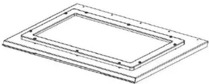
Step 1 Assemble the viewing window
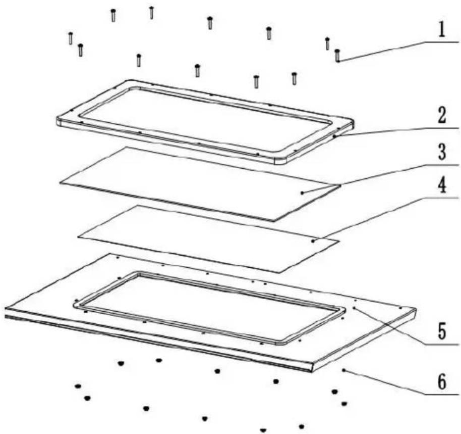
Put the plexiglass(No.3) which is sticked protective film(No.4) on the window sheet(No.5), then cover the plastic frame(No.2). Fix above 3 parts by cross p head screw and nut of M5*25(No.1&6).
Note:
The side with protective film (No.4) of plexiglass should be downwards.
Step 2 Assemble Sand funnel
- Connect big funnel plate(No.6) with small funnel plate(No.5) by M68 pan head screw(No.7),washer and nut(No.3). Wrap around the funnel mouth with sealing foam (2 circles). Fix the funnel box (No.1) with funnel by M612 pan head screw(No.2) and flange nut (No.3)
Step 3 Assemble cabinet
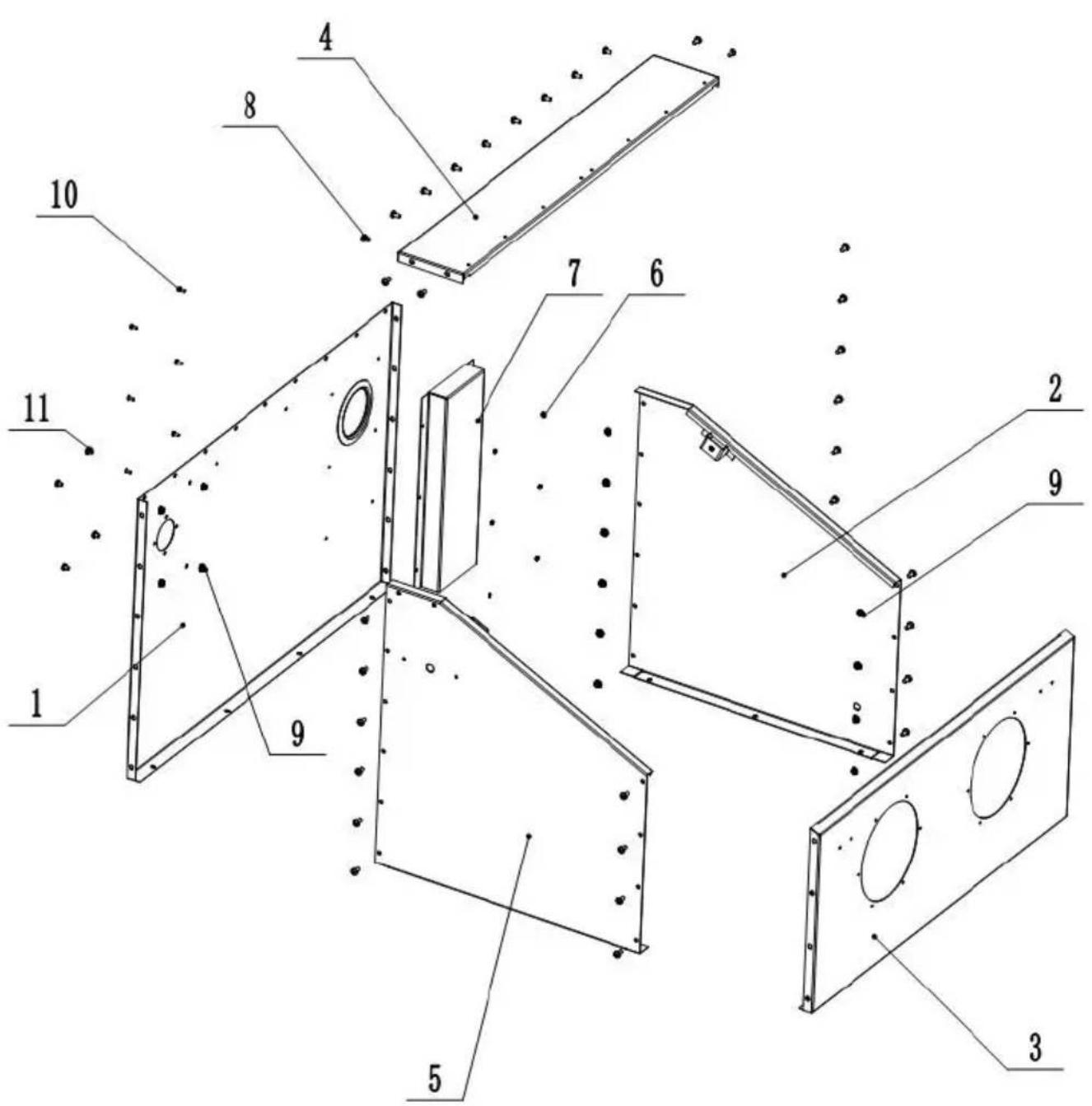
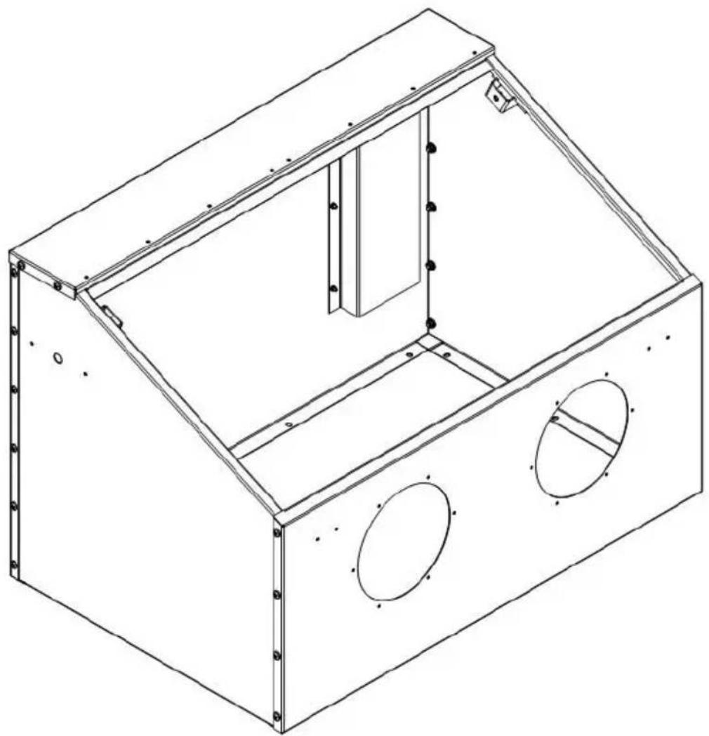
- Connect left cabinet plate(No.5), right cabinet plate(No.2) with rear cabinet plate(No.1) by M6*12 screw(No.8).
- Connect front plate(No.3) with left and right cabinet plates by M6*12 screw
- Fix top cabinet plate(No.4) with rear, left and right cabinet plates by M6*1 screw.
- Fix the air inlet cover (No.7) to rear plate by M4^*10 screw.
- Screw M6*8 (No.11&9) the 4 holes in the rear plate.
Note: The 4 holes prepare for dust collector assembly. If assemble dust collector, block the flange holes by screws before working.
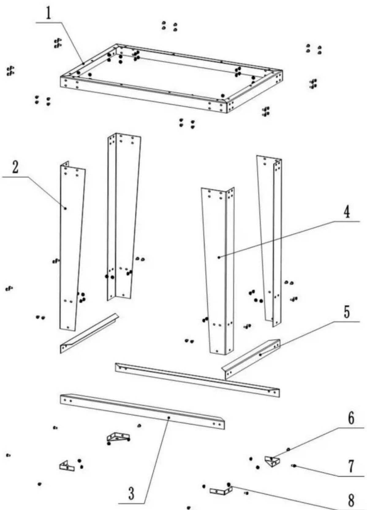
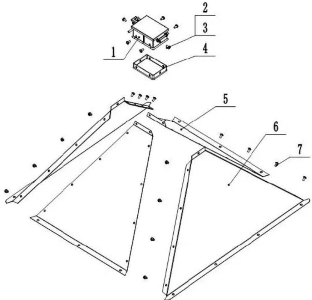
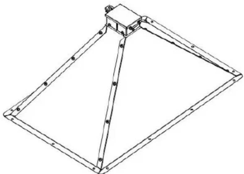
Step 4 Assemble leg


- Fix triangle(No.6) to legs (No.4) by screw M612 (No.7) and flange nut (No 2. Fix the left ((No.2)) and right leg(No.4) to leg frame (No.1) by screw M6 flange nut.
- Fix the long stiffener(No.3) and short stiffener (No.5) to four legs by screw M6*12 and flange nut.
Step 5 Assemble cabinet and legs
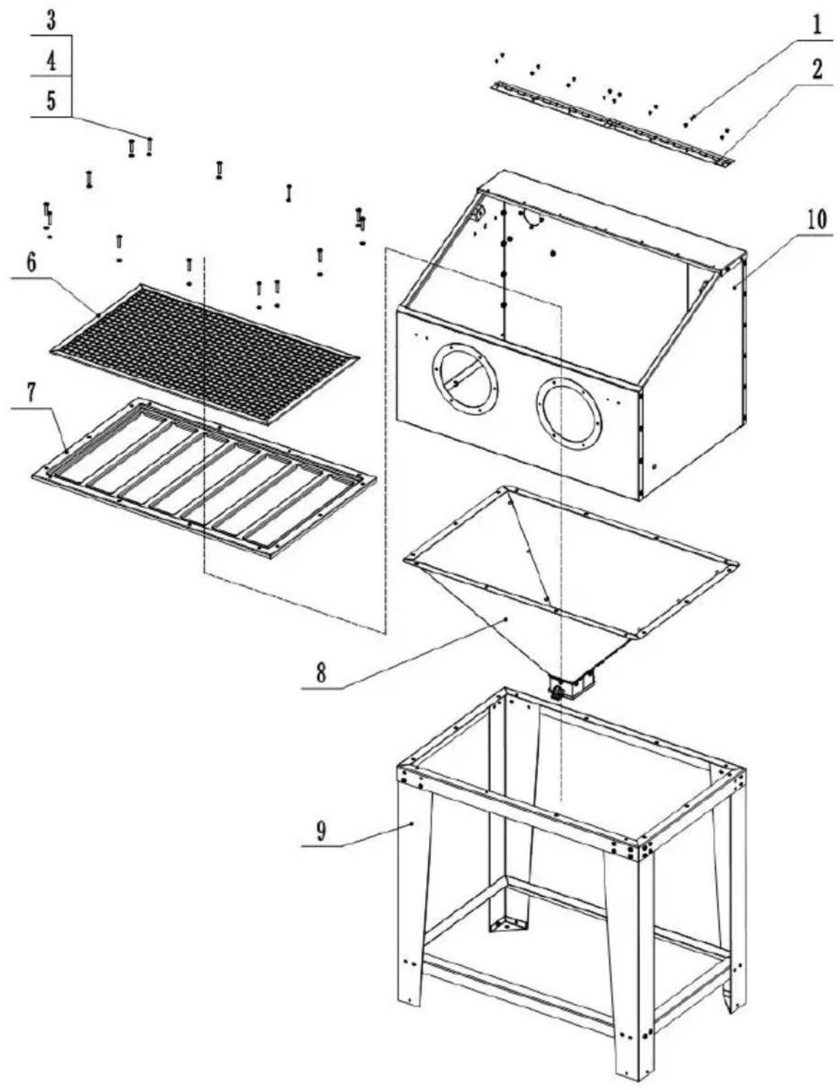
- Put the sand funnel (No.8) into the legs frame (No.9).
- Put whole cabinet (No.10) into the legs frame.
- Put net frame (No.7) into cabinet and fix with legs by screw M635 (No.3),washer (No.4) and nut (No.5).
4.Put the working net (No.6) into cabinet.
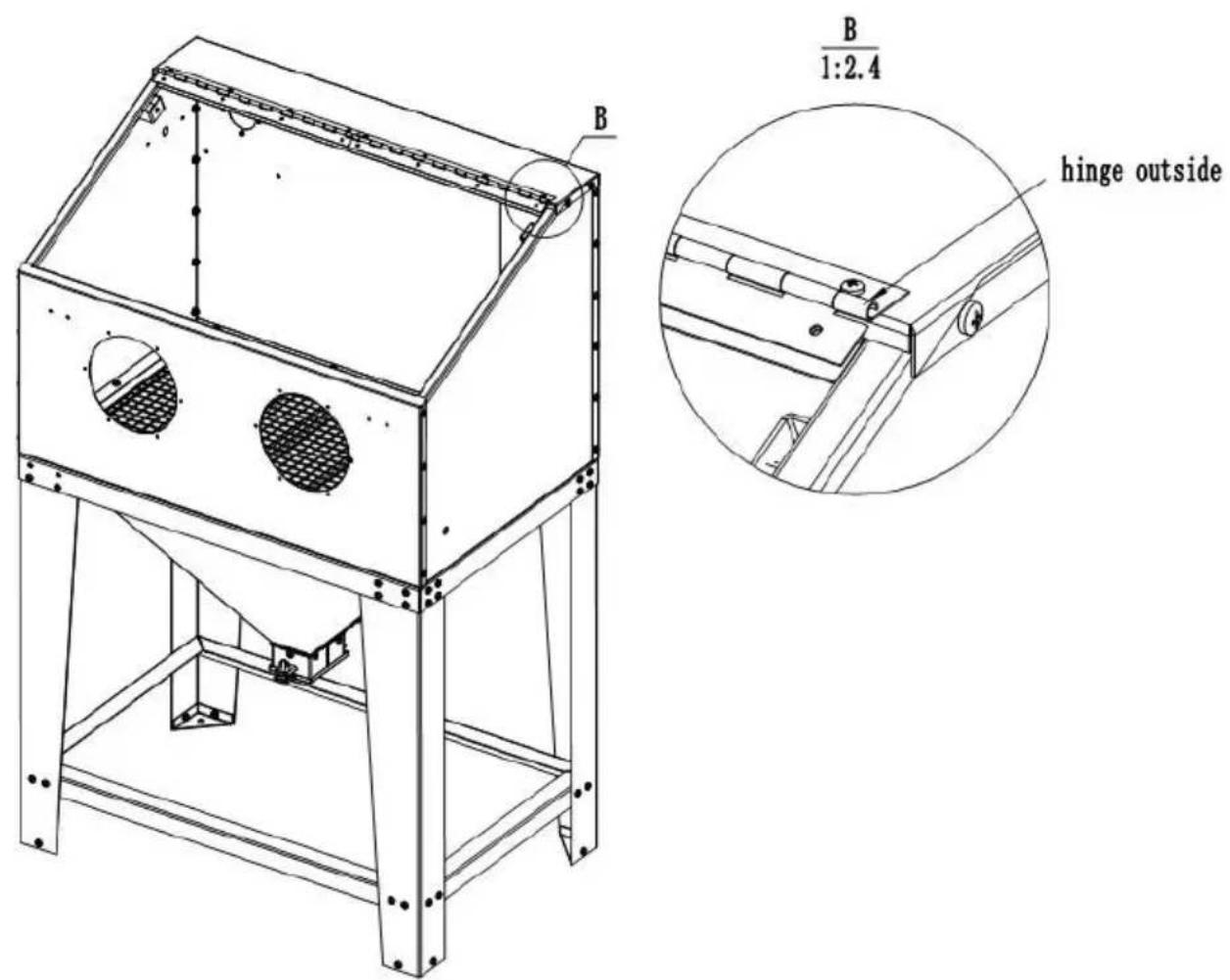
5.Fix the hinges(No.2) with cabinet by screw M410 and nut.
Note: Please take care the direction when assemble hinge (show as pic.)
Step6 Assemble blasting gun
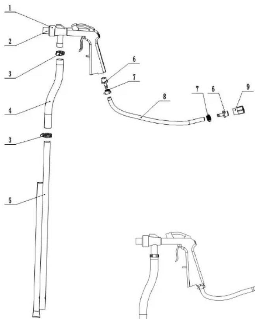
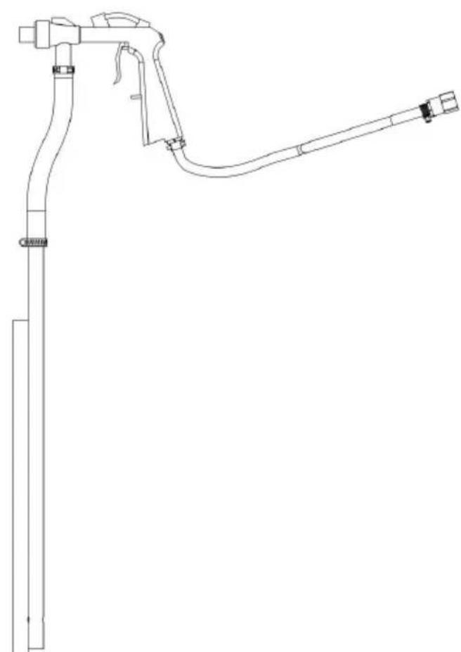
- Connect sand hose (No.4) with gun(No.2), clamp (No.3)itConnect sand pipe (No.5) into sand hose and clamp it tightly.
- Connect air hose (No.8) with gun and clamp(No.7) it. Then connect air connector (No.6), inner thread connector(No.9). Please wrap 5 circles teflon taclockwise rotation on the air connector to avoid leakage.
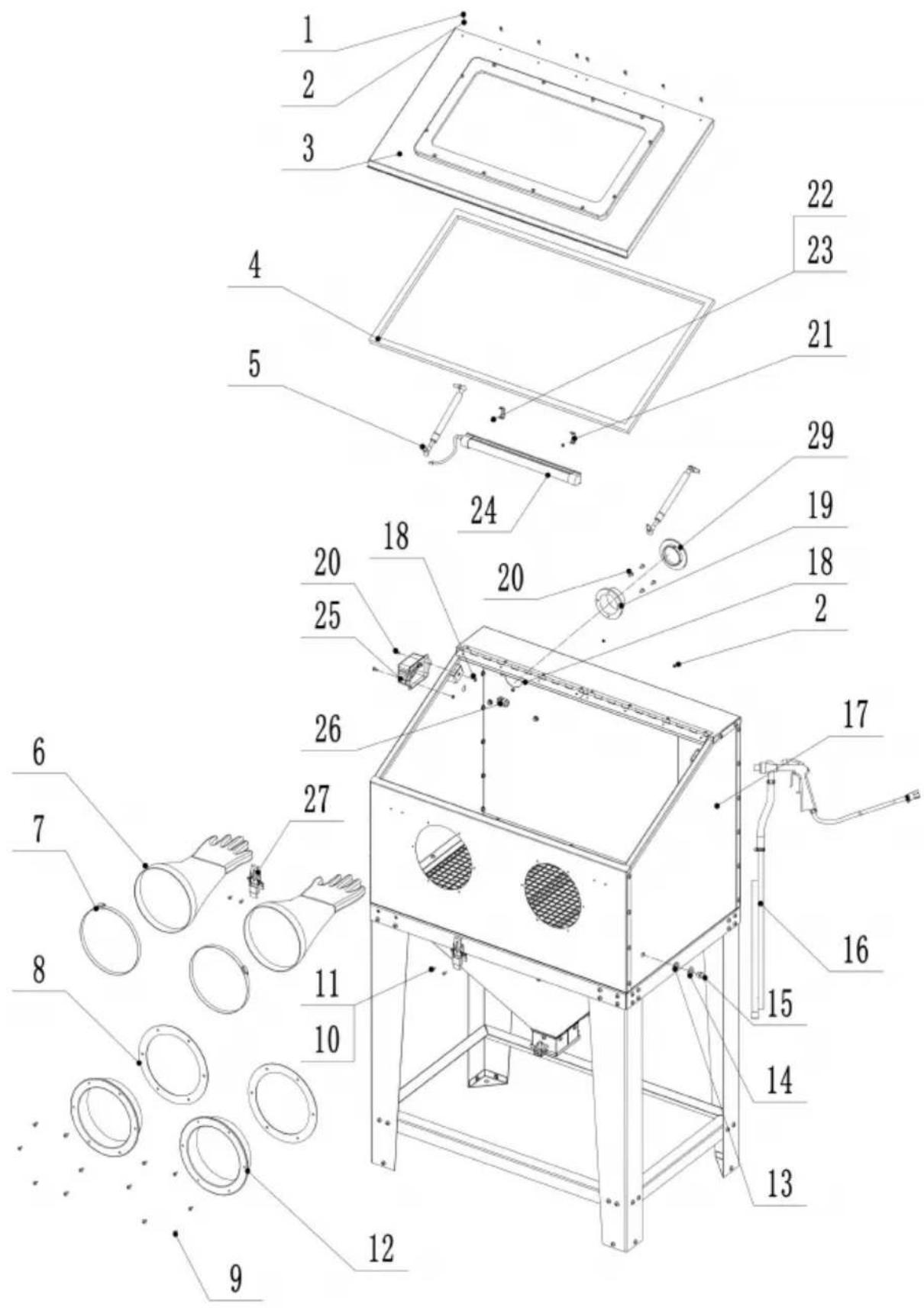
Step7 Assemble full machine
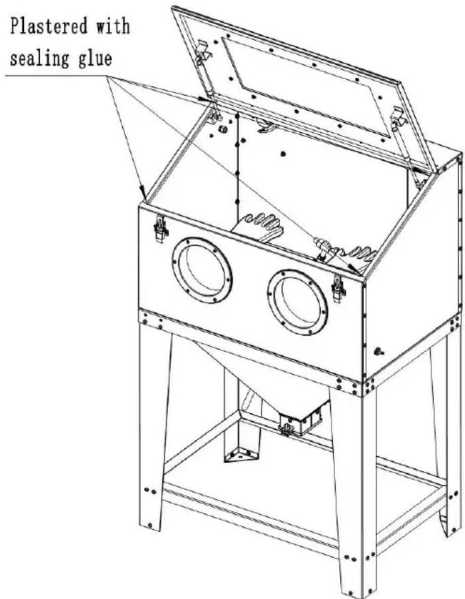
Note: Apply sealant at the joint of the four corners and leave for 24 hours before use;
- Install sandblasting gun assembly (No.6) inside cabinet (No.17), put the right (No.14) and metal washer (No.13) to the air connector (No.15). Then insert a hole of right cabinet plate and screw with inner thread connector.
Please note to wrap the teflon tape for connector if necessary. To make sure leakage.
2.Assemble the gloves fixer (No.12) with rubber washer (No.8) to the front cabinet plate by ST4.814 screws (No.9). Fix the gloves (No.6) to the plastic plastic e and clamp (No.7) them tightly. It should be operated from inside direction.
3.Install the door locker(No.27) in the front cabinet plate by M410 screw (No. 1 and nut(No.11).
4.Fix the lamp clips (No.21) to rear cabinet plate by M410 screw (No.22) and nut(No.23). Lock the lamp(No.24), put the lamp cable into the sealing joint(No.25). Insert the joint into the hole of left cabinet plate and screw it tightly. Connect lamp cable to switch box(No.25) and fix the box on the cabinet by M510 s (No.20) and nut(No.18).
5.Install the flange (No.19) by M510 screw (No.20) and nut(No.18) to rear plate if no dust collector needed and screw other four holes. If dust collector attached, no necessary to install flange, just screw the four flange holes.
6.Install the top plate with viewing window(No.3) to the hinge by M410 screw (No.1) and nut(No.2).
7. Fix the gas spring (No.5) to viewing window and cabinet.
8. Stick the sealing foam (No.4) around the inside of the viewing window.
Note:
- The sealing joint should be unscrewed, then insert the wires and screw a
- The stainless steel parts of air spring should be downwards.
AIR REQUIREMENTS:
For best results, we recommend a good 5HP air compressor. A small nozzle/air jet Combo is use with a 3HP air compressor.
| No | Name | Q'ty. | No | Name | Q'ty |
| 1 | Triangular mat | 4 | 32 | Teflon tape | 1 |
| 2 | Nozzle(5, 6, 7) | 3 | 33 | silicone sealant | 1 |
| 3 | Sealing joint | 1 | 34 | Gas spring | 2 |
| 4 | Switch box | 1 | 35 | Flange | 1 |
| 5 | Funnel box | 1 | 36 | Flange cover | 1 |
| 6 | Blasting gun( with 1 nozzle 1 air connector) | 1 | 37 | Inner thread connector 1/4" | 1 |
| 7 | Sealing foam 3M | 1 | 38 | Sand hose | 1 |
| 8 | Lamp clip | 2 | 39 | Sand pipe | 1 |
| 9 | Led Lamp | 1 | 40 | Plexiglass protective film | 3 |
| 10 | Door locker | 2 | 41 | Window frame | 1 |
| 11 | Plexiglass (with 1 film) | 1 | 42 | Window plate | 1 |
| 12 | Front cabinet plate | 1 | 43 | Net frame | 1 |
| 13 | Rear cabinet plate | 1 | 44 | Working net | 1 |
| 14 | Top cabinet plate | 1 | 45 | Small funnel plate | 2 |
| 15 | Right cabinet plate | 1 | 46 | Left leg | 2 |
| 16 | Left cabinet plate | 1 | 47 | Right leg | 2 |
| 17 | Leg frame | 1 | 48 | Air hose | 1 |
| 18 | Long stiffener | 2 | 49 | Sealing foam | 1 |
| 19 | short stiffener | 2 | 50 | Air connector1/4-Ø6 | 2 |
| 20 | Hinge | 2 | 51 | Glove (pair) | 1 |
| 21 | Glove fixer | 2 | 52 | Air inlet cover | 1 |
| 22 | Glove clamp | 2 | 53 | Transformer | 1 |
| 23 | Glove fixer washer | 2 | 54 | Manual | 1 |
| 24 | Cross pan head screw M4*10 | 26 | 55 | Cross countersunk screwM4*10 | 2 |
| 25 | Cross pan head screw M5*25 | 12 | 56 | Clamp Ø16-Ø25 | 2 |
| 26 | Hex flange nut M5 | 18 | 57 | Clamp Ø8-Ø12 | 2 |
| 27 | Cross pan head screw M5*10 | 6 | 58 | Cross pan head screw M6*12 | 95 |
| 28 | Cross pan head screw M6*35 | 14 | 59 | Cross tapping screw ST4.8*14 | 12 |
| 29 | Hex flange nut M6 | 129 | 60 | Hex nut M4 | 28 |
| 30 | Cross pan head screw M6 | 20 | 61 | Rubber washer Ø12.5 | 1 |
| 31 | Steel washer Ø6 | 14 | 62 | Steel washer Ø13 | 1 |
Important Note:
- Due to logistics reasons, few metal sheets may become slight deformed, which could to be corrected by simple tools. Normally easily done. But please consult customer service if the correction still not in place after you try. Customer service staff will provide proper solutions in time.
- The sealing foam can be punctured with a screwdriver before assembly to facilitate the installation of screws (the holes would hidden by sealing foam).
FCC Information
CAUTION: Changes or modifications not expressly approved by the par responsible for compliance could void the user's authority to operate t equipment!
This device complies with Part 15 of the FCC Rules. Operation is such the following two conditions:
1) This product may cause harmful interference.
2) This product must accept any interference received, including interference that may cause undesired operation.
WARNING: Changes or modifications to this product not expressly approved by the party.responsible for compliance could void the user's authority to operate the product.
Note: This product has been tested and found to comply with the IIR a Class B digital device pursuant to Part 15 of the FCC Rules, The are designed to provide reasonable protection against harmful interferer in a residential installation.
This product generates, uses and can radiate radio frequency energy, if not installed and used in accordance with the instructions, may cause harmful interference to radio communications. However, there is no guarantee that interference will not occur in a particular installation. If product does cause harmful interference to radio or television reception, which can be determined by turning the product off and on, user is encouraged to try to correct the interference by one or more following measures.
- Reorient or relocate the receiving antenna.
- Increase the distance between the product and receiver.
- Connect the product to an outlet on a circuit different from that to the receiver is connected.
· Consult the dealer or an experienced radio/TV technician for assista
CORRECT DISPOSAL

This product is subject to the provision of european Direct 2012/19/EU. The symbol showing a wheelie bin crossed through indicates that the product requires separate refuse collection in the European Union. This applies to the proof and all accessories marked with this symbol. Products marked as such may not be discarded with normal dome
waste, but must be taken to a collection point for recycling electrical electronic devices.
Address: Shuangchenglu 803nong11hao1602A-1609shi, baoshanqu, shanghai 200000 CN.
Imported to AUS: SIHAO PTY LTD. 1 ROKEVA STREETEASTWOOD NSW 2122 Australia
Imported to USA: Sanven Technology Ltd. Suite 250, 9166 Anaheim Place, Rancho Cucamonga, CA 91730

YH CONSULTING LIMITED.
C/O YH Consulting Limited Office 147,
Centurion House, London Road,
Staines-upon-Thames, Surrey, TW18 4AX

E-CrossStu GmbH.
Mainzer Landstr.69, 60329 Frankfurt am Ma
VEVOR
TOUGH TOOLS, HALF PRICE
Technical Support and E-Warranty Certificate
www.vevor.com/support