NMDP52-G50-70-12 - Water pump Vevor - Free user manual and instructions
Find the device manual for free NMDP52-G50-70-12 Vevor in PDF.

| Product Type | 12V Potable Water Pump |
| Compatible Model | NMDP52-G50-70-12 / NMDP52-G55-70-12 |
| Rated Voltage | 12 V DC |
| Rated Pressure | 70 PSI |
| Max Flow | 5.0 GPM (NMDP52-G50-70-12) or 5.5 GPM (NMDP52-G55-70-12) |
| Number of Chambers | 5 |
| Inlet/Outlet Diameter | 1/2" MNPT |
| Pump Type | Diaphragm Pump |
| Priming | Self-priming up to 6 vertical feet |
| Dry Run | Possible for normal loads |
| Control | Automatic by pressure switch |
| Integrated Bypass | Yes, reduces cycling |
| Electrical Protection | 15 A fuse recommended on dedicated circuit |
| Mounting | Variable position; vertical with head down to avoid leaks |
| Applications | Yacht, RV, spraying, cleaning, water purification, etc. |
| Included Accessories | Hose adapters (2), filter, bolt, sealing tape, 3/4" copper adapter |
| Spare Parts | Pressure switch, diaphragm, bypass valve, pump head, motor |
| Maintenance | Disinfection and winterization before/after storage |
| Safety | Do not exceed 30 PSI inlet pressure |
| Repairability | Bypass adjustment by professional technician |
Frequently Asked Questions - NMDP52-G50-70-12 Vevor
User questions about NMDP52-G50-70-12 Vevor
0 question about this device. Answer the ones you know or ask your own.
Ask a new question about this device
Download the instructions for your Water pump in PDF format for free! Find your manual NMDP52-G50-70-12 - Vevor and take your electronic device back in hand. On this page are published all the documents necessary for the use of your device. NMDP52-G50-70-12 by Vevor.
USER MANUAL NMDP52-G50-70-12 Vevor
Technical Support and E-Warranty Certificate
www.vevor.com/support
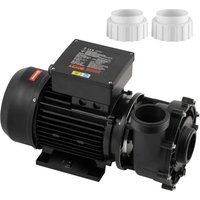
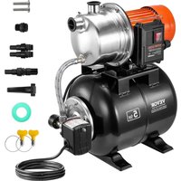
12 VOLT POTABLE WATER PUMP
MODEL: NMDP52-G50-70-12 / NMDP52-G55-70-12
We continue to be committed to provide you tools with competitive price. "Save Half", "Half Price" or any other similar expressions used by us only rep estimate of savings you might benefit from buying certain tools with us compared top brands and does not necessarily mean to cover all categories of tools offered are kindly reminded to verify carefully when you are placing an order with us actually saving half in comparison with the top major brands.
MODEL:NMDP52-G50-70-12/NMDP52-G55-70-12

natural_image
Technical line drawing of a mechanical assembly with gears and housing (no text or symbols)NEED HELP? CONTACT US!
Have product questions? Need technical support? Please feel fr contact us:
Technical Support and E-Warranty Certificate www.vevor.com/support
This is the original instruction, please read all manual instruction carefully before operating. VEVOR reserves a clear interpretation user manual. The appearance of the product shall be subject to product you received. Please forgive us that we won't inform you there are any technology or software updates on our product.
 | Warning-To reduce the risk of injury, user must read instruct manual carefully. |
 | CORRECT DISPOSALThis product is subject to the provision of European Directive 2012/19/EU. The symbol showing a wheelie bin crossed through indicates that the product requires separate refuse collection in European Union. This applies to the product and all accesso marked with this symbol. Products marked as such may not discarded with normal domestic waste, but must be taken to acollection point for recycling electrical and electronic devices. |
An economical workhorse, the 52 Series is engineered for flexibility. The 5-chamber series is our Heavy-Duty water pump. It provides high-volume water flow with reduced pump cycling, thanks to the large five-chamber diaphragm. With the on- demand switch, 5.0GPM or 5.5GPM, and 70 PSI 52 Series will meet your special requirements with positive predictable performance. With a built-in bypass function, the 52 Series can reduce ra cycling and allow water to flow back from the outlet side to the inlet sic pump. We also offer a variety of easy-connect fittings and filters.
PRODUCT SPECIFICATIONS
| Property | Specifications | |
| NMDP52-G50-70-12 | NMDP52-G55-70-12 | |
| Rated Voltage | DC12V | DC12V |
| Rated Pressure | 70 PSI | 70 PSI |
| Number of Chamber | 5 PCS | 5 PCS |
| Max. Flow | 5.0 GPM | 5.5 GPM |
| Inlet/Outlet Diameter | 1/2" MNPT | 1/2" MNPT |
An incredible feature list, high-quality components, plus amazing performance. The five-chamber high-volume design, driven by a heavy-duty motor product flow rates of 5.0GPM or 5.5 GPM, capable of self-priming up to 6 vertical and can run dry, making it the price-to-performance leader. This pump also offers a variety of easy-connect fittings and filters.
FEATURES
-5-chamber diaphragm pump
·Continuous duty
- Industrial-standard mounting pattern
- Run dry capable for normal workloads
·Automatic: controlled by pressure switch
·Self priming
·Quiet Operation
·Ignition protected Bypass: reduces cycling
APPLICATIONS
·Yacht/RV/caravan pressurized water system
- Sprayer fixtures (vehicle-mounted sprayers, electric sprayers)
·Cleaning machines Humidifiers water purification, medical apparatus
·Food beverage filling & liquid transfer
·Solar water system
·Any other pressurization system
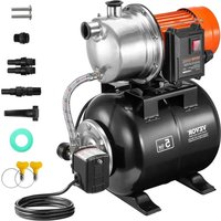
INSTALLATION
Materials
1.diaphragm pump with related accessories
2.(at least) pieces of flexible, reinforced hose piping, with collapsing strength twice the inlet collapsing pressure(hose must be minimum 1/2"D)
3.stainless steel hose clamps and screws
4.screws to fasten the pump to the mounting surface
1 electrical cut off switch
1 fuse
1 screwdriver
1 strong cutting implement for tubing (if desired)Teflon tape or sealant
Setup
- The pump may be mounted in any position. If mounted vertically, the head should be in the down position to avoid leakage into the motor case the event of a malfunction.
- Secure the feet, but do not compress them. Over tightening the secure screws may reduce their ability to dissipate noise and vibration.
- The inlet and outlet hoses must be 1/2" (13 mm) ID reinforced hoses. diameter of branch and individual supply lines from the outlet should be smaller than 3/8"(10 mm).
- Plumb the system using high pressure (2 x pump rating), braided, flex tubing to minimize vibration/noise.
- Do not apply inlet pressure in excess of 30psi. In general, try to avoid inlet pressure completely.
- Avoid any kinks or fittings which could cause excessive restrictions.
7.Strainer should be attached to the inlet side. - The fittings must be secured to avoid leakage
- Use clamps at both ends of the hose to prevent air leaks into the wa
- If a check valve is installed in the plumbing, it must have a cracking pressure of no more than 2 psi.
- If applying a sealer or plumbing tape, be careful not to over tighten, may be sucked into.
- This pump should be wired on its own dedicated circuit. Connect the positive lead (red) to the positive terminal of your battery and the negative wire(black) to the negative terminal of your battery.
- In an easily accessible location, install a switch to control electricity to pump. Turn the pump off when not used for extended periods or when it is empty.
- The electrical circuit should be protected with an over-current protection
device(fuse) in the positive lead. This pump requires a 15 amp fuse.
- The pump circuit should not include any other electrical loads.
- As the water supply pump is non-essential, reference the wire Chart the electrical information. Be sure to have the correct wire sizing for the of wire you are using.
- After installation, check the voltage at the pump motor. Voltage should be checked when the pump is operating. Full voltage must be available at the pump motor at times.
Notes
- Flexible potable water hose or PEX tubing is recommended instead of piping at the pump. If you choose to use rigid piping, provide a short le hose between the pipe and the pump to avoid noise and vibration.
- We do not recommend the use of metal fittings. When possible, use provided plastic fittings.
- Do not adjust the bypass personally without the help of a technician.
- Lack of sanitizing and maintenance is one of the main reasons for the underperformance of the pump. Please do maintenance and winterize the pump at appropriate times, especially before and after a period of storage
ACCESSORIES
| Item | Quantity |
| Hose Adapter | 2 |
| Filter | 1 |
| Hexagon Bolt | 1 |
| Sealing Tape | 1 |
| 3/4" Copper Hose Adapter | 1 |
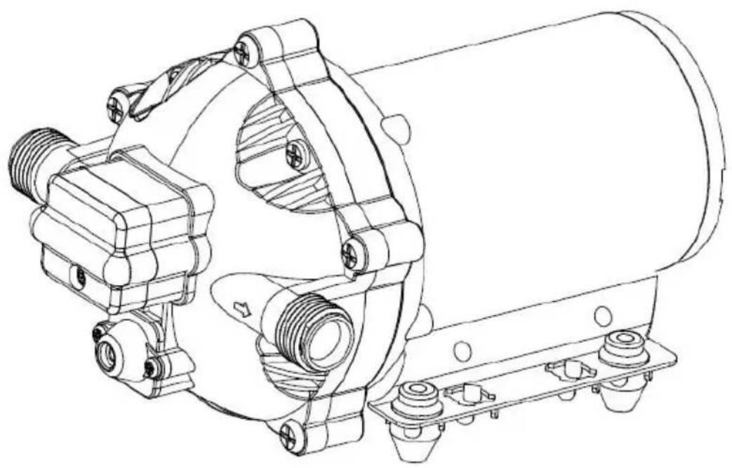
EXPLODED VIEWS
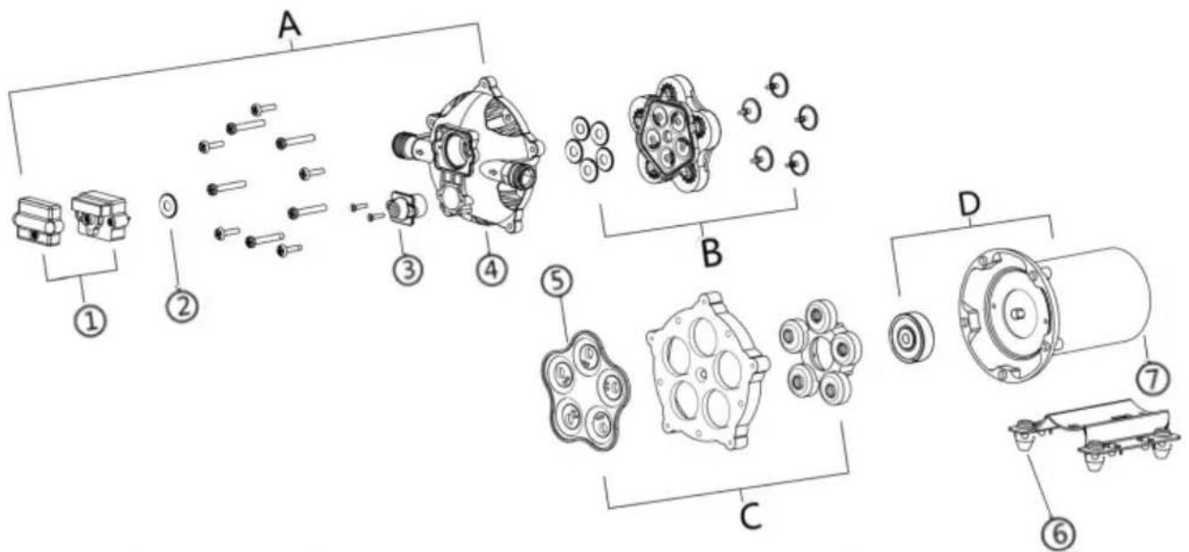
| KEY | Description | Quantity |
| 1 | Pressure Switch | 1 |
| 2 | Diaphragm of Pressure Switch | 1 |
| 3 | Bypass Valve | 1 |
| 4 | Pump Head | 1 |
| 5 | Diaphragm | 1 |
| 6 | Iron Feet Group | 1 |
| 7 | Motor | 1 |
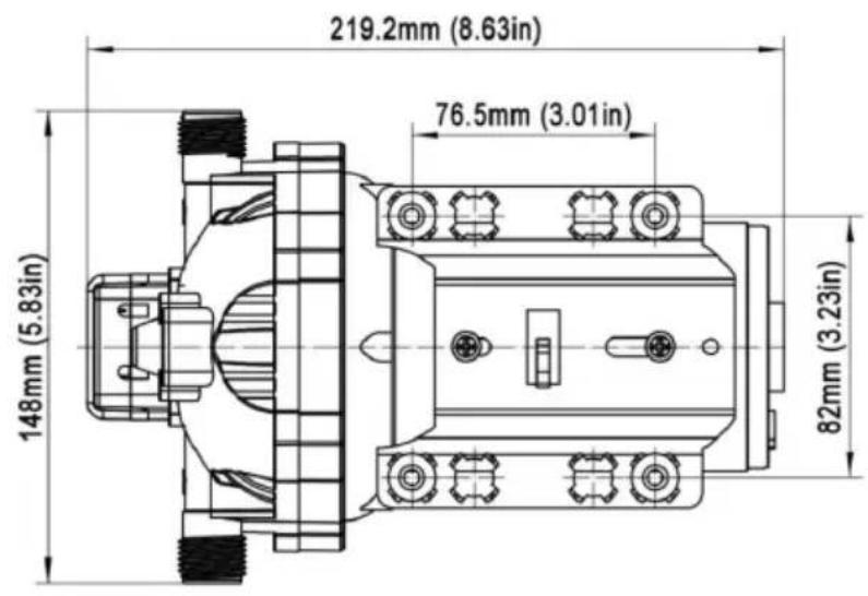
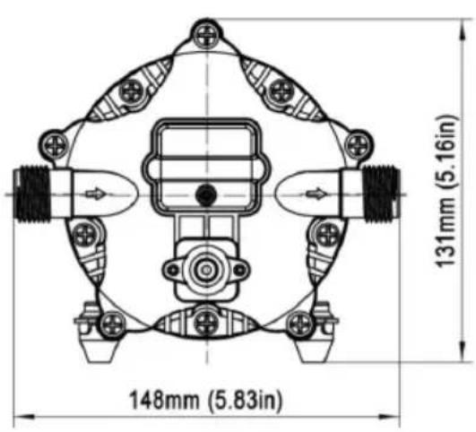
PRODUCT SIZE

TROUBLESHOOTING
PULSATING FLOW- PUMP CYCLES ON AND OFF
- Check lines for kinks.
- Plumbing lines or fittings may be too small.
·Clean faucets and filters. - Check fitting tightness for air leaks.
FAILURE TO PRIME BUT MOTOR OPERATES-NO PUMP DISCHARGE
·Restricted in take or discharge line.
·Air leak in intake line.
·Punctured pump diaphragm
The initial amp supply is not enough to sufficiently start the motor.
- Debris clogs in the valves.
- Crack in the pump housing.
MOTOR FAILS TO TURN ON
- Loose or improper wiring.
- The pump circuit has no power.
- Blown fuse.
- Failed pressure switch.
- Defective motor.
PUMP FAILS TO TURN OFF AFTER ALL FIXTURES ARE CLO
- Punctured diaphragm.
- Discharge line leak
- Defective pressure switch.
- Insufficient voltage.
• Clogged valves in the pump head.
LOW FLOW AND PRESSURE
· Air leak at the pump intake.
- Accumulation of debris inside pump or plumbing.
- Worn pump bearing (possibly accompanied by loud noise).
- Punctured diaphragm.
- Defective motor.
NOISY
- Check if the mounting feet are compressed too tightly.
- Is the mounting surface flexible? If so, it may be adding noise.
- Check for loose head/screws.
- If the pump is plumbed with rigid pipe, then it may transmit noise more USE THE FOLLOWING PROCESS TO ADJUST SHUT-OFF AND BY-PASS PRESSURES
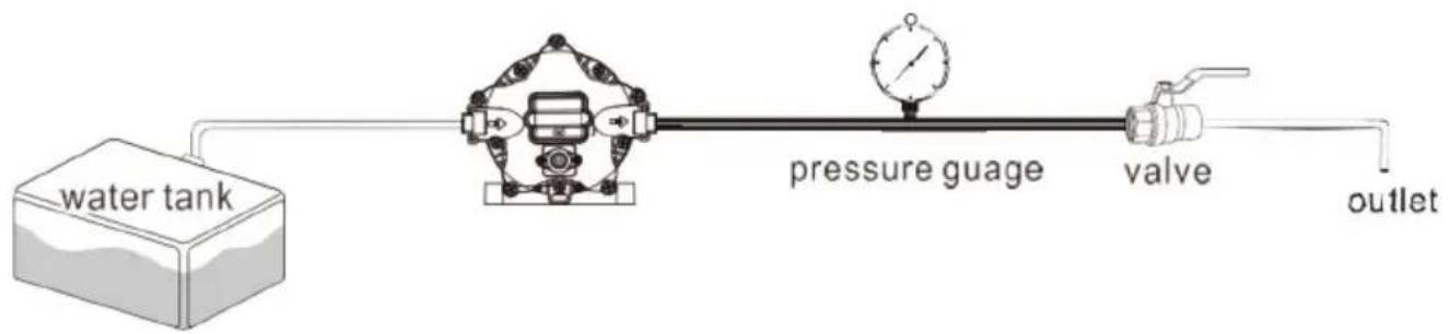
flowchart
graph LR
    A["water tank"] --> B["Pressure Gauge"]
    B --> C["Valve"]
    C --> D["outlet"]
1. install the pump as in picture
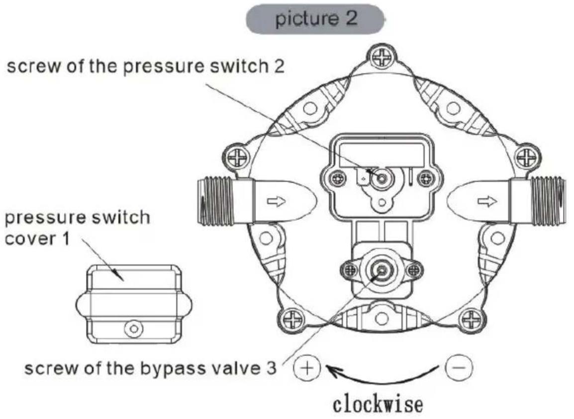
ADJUSTING THE BYPASS VALVE AND PRESSURE SWITCH

TIP: Bypass adjustment should be performed by a professional technic using a proper gauge and equipment. Without the proper equipment, you could mis-adjust the valve or switch causing the pump to work improperly Caution below).
About the Bypass Valve
The pump uses a spring-loaded bypass valve to maintain smooth performance
as water demands rise and fall. When a faucet is turned on the pump i providing full water flow, so the bypass valve is closed. But when there to no water demand, the bypass valve opens to allow water to flow back the outlet side to the inlet side, keeping a steady flow of water within th with almost no cycling.
ADJUSTING THE PUMP'S SHUT-OFF PRESSURE:
Step 1: Remove pressure switch cover(No.1)
Step 2: Fine-tune the pressure adjustment screw (serial number 2) pressure switch with a 2mm wrench, if you want to increase the p turn it clockwise, if you want to decrease the pressure, turn it counterclockwise.
Step 3: After adjusting the pressure of the pressure switch, the pres the bypass valve should be adjusted accordingly. Use a 2mm wren fine-tune the bypass valve screws (serial number 3), if you want to the pressure, turn it clockwise, if you want to decrease the pressure counterclockwise.
Step 4: Install the pressure switch cover (No.1)
CAUTION:
The pressure setting for full bypass must be at least 8psi higher than shut-off pressure of the pump. If the switch and bypass is adjusted closely, the bypass and switch shut-off can overlap and the pump will shut off.
ABOUT THE BYPASS
Please consult a professional technician in case the bypass needs adjustment. Improper adjustment of the bypass may damage the pump. The bypass comes preset for optimal operation of the pump. If your application calls for a different setting for the bypass, you may change yourself. Carefully tighten the screw to increase or loosen the screw decrease the minimum operating pressure of the bypass.
CAUTION
Please do follow the instruction manual to install the product. Any act outside what is recommended in this manual may bring damage to the pump.
*There are any minor changes to the numbers included in the user I without prior notice.
VEVOR®
TOUGH TOOLS, HALF PRICE
Technical Support and E-Warranty Certificate www.vevor.com/support
VEVOR®
TOUGH TOOLS, HALF PRICE
We continue to be committed to provide you tools with competitive price. "Save Half", "Half Price" or any other similar expressions used by us only rep estimate of savings you might benefit from buying certain tools with us compared top brands and does not necessarily mean to cover all categories of tools offered are kindly reminded to verify carefully when you are placing an order with us actually saving half in comparison with the top major brands.
MODÈLE : NMDP52-G50-70-12 / NMDP52-G55-70-12
natural_image
Technical line drawing of a mechanical assembly with gears and housing (no text or symbols)NEED HELP? CONTACT US!
Have product questions? Need technical support? Please feel fr contact us:
Technical Support and E-Warranty Certificate www.vevor.com/support
This is the original instruction, please read all manual instruction carefully before operating. VEVOR reserves a clear interpretation user manual. The appearance of the product shall be subject to product you received. Please forgive us that we won't inform you there are any technology or software updates on our product.
PRODUCT SPECIFICATIONS

TROUBLESHOOTING
DÉBIT PULSÉ - LA POMPE FONCTIONNE PAR CYCLES DE MARCHE ET D'ARRÊT
ABOUT THE BYPASS
www.vevor.com/support
12-VOLT-TRINKWASSERPUMPE
MODELL: NMDP52-G50-70-12 / NMDP52-G55-70-12
We continue to be committed to provide you tools with competitive price. "Save Half", "Half Price" or any other similar expressions used by us only rep estimate of savings you might benefit from buying certain tools with us compared top brands and does not necessarily mean to cover all categories of tools offered are kindly reminded to verify carefully when you are placing an order with us actually saving half in comparison with the top major brands.
MODELL: NMDP52-G50-70-12 / NMDP52-G55-70-12

natural_image
Technical line drawing of a mechanical assembly with gears and housing (no text or symbols)NEED HELP? CONTACT US!
Have product questions? Need technical support? Please feel fr contact us:
Technical Support and E-Warranty Certificate www.vevor.com/support
This is the original instruction, please read all manual instruction carefully before operating. VEVOR reserves a clear interpretation user manual. The appearance of the product shall be subject to product you received. Please forgive us that we won't inform you there are any technology or software updates on our product.
PRODUCT SPECIFICATIONS
TROUBLESHOOTING
ABOUT THE BYPASS
We continue to be committed to provide you tools with competitive price. "Save Half", "Half Price" or any other similar expressions used by us only represent of savings you might benefit from buying certain tools with us compared top brands and does not necessarily mean to cover all categories of tools offered are kindly reminded to verify carefully when you are placing an order with us actually saving half in comparison with the top major brands.
MODELLO: NMDP52-G50-70-12 / NMDP52-G55-70-12

natural_image
Technical line drawing of a mechanical assembly with gears and housing (no text or symbols)NEED HELP? CONTACT US!
Have product questions? Need technical support? Please feel fr contact us:
Technical Support and E-Warranty Certificate www.vevor.com/support
This is the original instruction, please read all manual instruction carefully before operating. VEVOR reserves a clear interpretation user manual. The appearance of the product shall be subject to product you received. Please forgive us that we won't inform you there are any technology or software updates on our product.
PRODUCT SPECIFICATIONS

TROUBLESHOOTING
ABOUT THE BYPASS
We continue to be committed to provide you tools with competitive price. "Save Half", "Half Price" or any other similar expressions used by us only rep estimate of savings you might benefit from buying certain tools with us compared top brands and does not necessarily mean to cover all categories of tools offer are kindly reminded to verify carefully when you are placing an order with us actually saving half in comparison with the top major brands.
MODELO: NMDP52-G50-70-12 / NMDP52-G55-70-12

natural_image
Technical line drawing of a mechanical assembly with gears and housing (no text or symbols)NEED HELP? CONTACT US!
Have product questions? Need technical support? Please feel fr contact us:
Technical Support and E-Warranty Certificate www.vevor.com/support
This is the original instruction, please read all manual instruction carefully before operating. VEVOR reserves a clear interpretation user manual. The appearance of the product shall be subject to product you received. Please forgive us that we won't inform you there are any technology or software updates on our product.
PRODUCT SPECIFICATIONS

TROUBLESHOOTING
FLUJO PULSANTE: LA BOMBA SE ENCIENDE Y APAGA CICLO
ABOUT THE BYPASS
www.vevor.com/support
POMPA DO WODY PITNEJ 12 V
MODEL: NMDP52-G50-70-12 / NMDP52-G55-70-12
We continue to be committed to provide you tools with competitive price. "Save Half", "Half Price" or any other similar expressions used by us only rep estimate of savings you might benefit from buying certain tools with us compared top brands and does not necessarily mean to cover all categories of tools offered are kindly reminded to verify carefully when you are placing an order with us actually saving half in comparison with the top major brands.
MODELE: NMDP52-G50-70-12 / NMDP52-G55-70-12

natural_image
Technical line drawing of a mechanical assembly with gears and housing (no text or symbols)NEED HELP? CONTACT US!
Have product questions? Need technical support? Please feel fr contact us:
Technical Support and E-Warranty Certificate www.vevor.com/support
This is the original instruction, please read all manual instruction carefully before operating. VEVOR reserves a clear interpretation user manual. The appearance of the product shall be subject to product you received. Please forgive us that we won't inform you there are any technology or software updates on our product.
PRODUCT SPECIFICATIONS

TROUBLESHOOTING
PRZEPLYW PULSUJACY - CYKLE POMPY WŁĄCZONE I WYŁĄCZONE
ABOUT THE BYPASS
We continue to be committed to provide you tools with competitive price. "Save Half", "Half Price" or any other similar expressions used by us only rep estimate of savings you might benefit from buying certain tools with us compared top brands and does not necessarily mean to cover all categories of tools offered are kindly reminded to verify carefully when you are placing an order with us actually saving half in comparison with the top major brands.
MODEL: NMDP52-G50-70-12 / NMDP52-G55-70-12

natural_image
Technical line drawing of a mechanical assembly with gears and housing (no text or symbols)NEED HELP? CONTACT US!
Have product questions? Need technical support? Please feel fr contact us:
Technical Support and E-Warranty Certificate www.vevor.com/support
This is the original instruction, please read all manual instruction carefully before operating. VEVOR reserves a clear interpretation user manual. The appearance of the product shall be subject to product you received. Please forgive us that we won't inform you there are any technology or software updates on our product.
PRODUCT SPECIFICATIONS
| Eigendom | Specificaties | |
| NMDP52-G50-70-12 | NMDP52-G55-70-12 | |
| Nominale spanning | DC 12V | DC 12V |
| Nominale druk | 70 PSI | 70 PSI |
| Aantal kamers | 5 STUKS | 5 STUKS |
| Maximale stroom | 5.0 GPM | 5,5 GPM |
| Inlaat-/uitlaatdiameter | 1/2" MNPT | 1/2" MNPT |

TROUBLESHOOTING
PULSERENDE STROOM - POMPCYCLI AAN EN UIT
POMP GAAT NIET UIT NADAT ALLE ARMATUREN GESLOTEN
ZIJN
ABOUT THE BYPASS
www.vevor.com/support
12 VOLT DRICKSVATTENPUMP
MODELL: NMDP52-G50-70-12 / NMDP52-G55-70-12
We continue to be committed to provide you tools with competitive price. "Save Half", "Half Price" or any other similar expressions used by us only rep estimate of savings you might benefit from buying certain tools with us compared top brands and does not necessarily mean to cover all categories of tools offered are kindly reminded to verify carefully when you are placing an order with us actually saving half in comparison with the top major brands.
MODELL: NMDP52-G50-70-12 / NMDP52-G55-70-12

natural_image
Technical line drawing of a mechanical assembly with gears and housing (no text or symbols)NEED HELP? CONTACT US!
Have product questions? Need technical support? Please feel free to contact us:
Technical Support and E-Warranty Certificate www.vevor.com/support
This is the original instruction, please read all manual instructions carefully before operating. VEVOR reserves a clear interpretation of our user manual. The appearance of the product shall be subject to the product you received. Please forgive us that we won't inform you again if there are any technology or software updates on our product.
PRODUCT SPECIFICATIONS
| Egendom | Specifikationer | |
| NMDP52-G50-70-12 | NMDP52-G55-70-12 | |
| Märkspänning | DC 12V | DC 12V |
| Nominellt tryck | 70 PSI | 70 PSI |
| Kammarens nummer | 5 st | 5 st |
| Max. Flöde | 5. 0 GPM | 5,5 GPM |
| Inlopps-/utloppsdiameter | 1/2" MNPT | 1/2" MNPT |

TROUBLESHOOTING
PULSERANDE FLÖDE- PUMP CYKLAR PÅ OCH AV
ABOUT THE BYPASS
www.vevor.com/support