MYJG150W - Power Supply Vevor - Free user manual and instructions
Find the device manual for free MYJG150W Vevor in PDF.

| Product Type | Power Supply for CO2 Laser |
| Brand | Vevor |
| Model | MYJG150W |
| Input Voltage | AC 100-240 V, 50/60 Hz |
| Max Output Current | 36 mA |
| Efficiency | 91% |
| Overcurrent Protection | 130% of maximum current |
| Open Circuit Protection | Yes (short duration) |
| Cooling | Fan |
| Operating Temperature | -30 °C to +65 °C |
| Relative Humidity | 20% to 85% RH (non-condensing) |
| Insulation Resistance | ≥50 MΩ (DC500V) |
| Vibration Resistance | Amplitude 0.5 mm, frequency 10-55 Hz, 3 axes, 3 hours |
| MTBF | ≥30,000 hours |
| Burn-in Test | 12 hours at 60 °C, 500 on/off cycles of 7 seconds |
| Laser Control | TTL high/low, PWM (20-50 kHz), analog 0-5 V |
| Water Flow Protection | Yes (protection switch) |
| Grounding | Mandatory (three-hole plug) |
| Feedback Interface | Yes (for closed-loop control) |
| Dimensions | Not specified in the manual |
| Weight | Not specified |
Frequently Asked Questions - MYJG150W Vevor
User questions about MYJG150W Vevor
0 question about this device. Answer the ones you know or ask your own.
Ask a new question about this device
Download the instructions for your Power Supply in PDF format for free! Find your manual MYJG150W - Vevor and take your electronic device back in hand. On this page are published all the documents necessary for the use of your device. MYJG150W by Vevor.
USER MANUAL MYJG150W Vevor
Technical Support and E-Warranty Certificate www.vevor.com/support
LASER POWER SUPPLY USER MANUAL
MODEL:MYJG40W, MYJG60W, MYJG80W, MYJG100W, MYJG150W,
We continue to be committed to provide you tools with competitive price. "Save Half", "Half Price" or any other similar expressions used by us only represents an estimate of savings you might benefit from buying certain tools with us compared to the major top brands and does not necessarily mean to co all categories of tools offered by us. You are kindly reminded to verify carefully when you are placing an order with us if you are actually Saving Half in comparison with the top major brands.
VEVOR®
TOUGH TOOLS, HALF PRICE
LASER POWER SUPPLY
natural_image
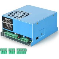
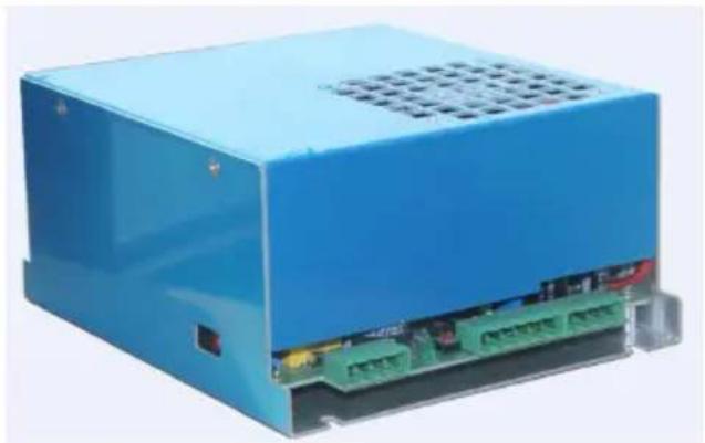
Blue industrial electronic device with green circuit board and ventilation grille (no visible text or symbols)MYJG40W
natural_image
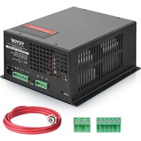
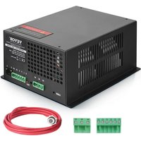
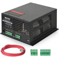
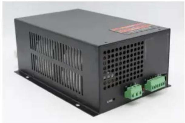
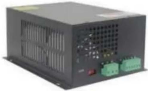
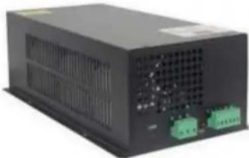
Black industrial power supply unit with ventilation slots and two green connectors (no visible text or symbols)(The picture is for reference only, please refer to the actual obje
NEED HELP? CONTACT US!
Have product questions? Need technical support? Please feel fr contact us:
Technical Support and E-Warranty Certificate www.vevor.com/support
This is the original instruction, please read all manual instruction carefully before operating. VEVOR reserves a clear interpretation user manual. The appearance of the product shall be subject to product you received. Please forgive us that we won't inform you there are any technology or software updates on our product.
Key features:
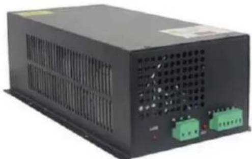
The product is a successful high-efficiency, high-frequency, high-speed CO2 laser supported powersupply, small size, light weight, easy to op with good matching performance for lasers. It can be directly connected with the laser, saving the bulky, and severe heating of resistance. The power supply can make the CO2 laser lighting easy, taking advantage the full performance of CO2 laser, improving conversion efficiency, and extending the life of the laser.
Key Technical Parameters:
- Input voltage: AC 100-240V
- Response speed: ≤ 1mS.
- TTL level switch control: effective level can be high and low select
- Protection switch: can be used for the detection of water, protection lasers, or protection when opening the housing, etc.
- Laser power regulation: (1) The output current of the laser power is regulated by the power meter. (2) controlled by PWM (TTL level).
- Feedback Interface: The power supply itself can have a feedback interface and can be used for closed-loop control to verify the actual working current of the laser.
- Environment of use: Temperature (-10 to 40 degrees C), humidity: 85%.
Instructions For Use:
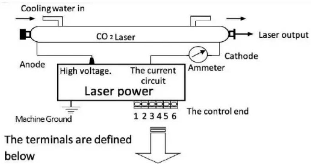
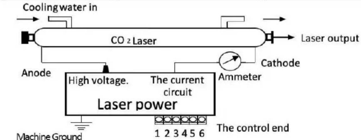
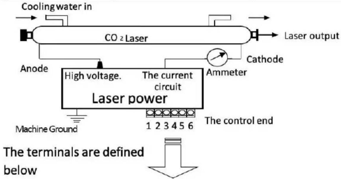
- Connection of the Laser Tube: The high-voltage (HV-plus) of the power supply must be connected to the anode (full reflector) of the laser tube. The current circuit of the laser power supply is connected to the cathode (laser output) of the CO2 laser tube via a current me directly)
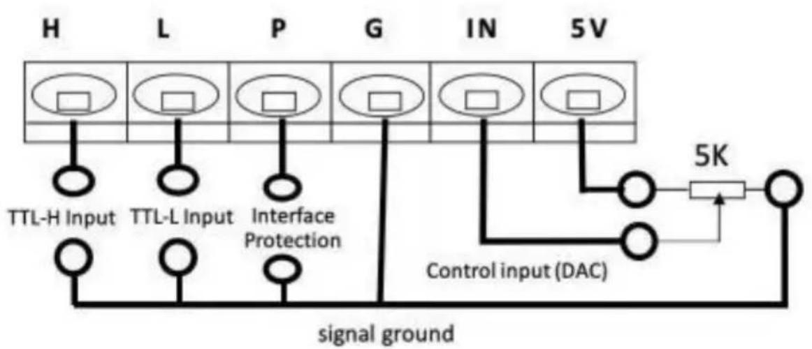
- Connection of the Control Signal: In Figure 1 (or Figure 2), the signal line is reliably connected to the control end of the laser power supply.
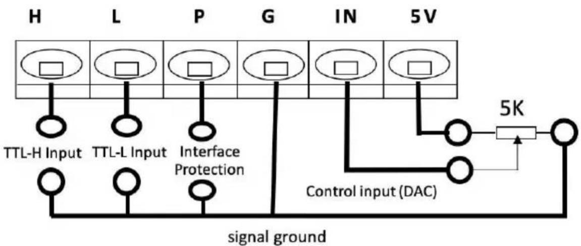
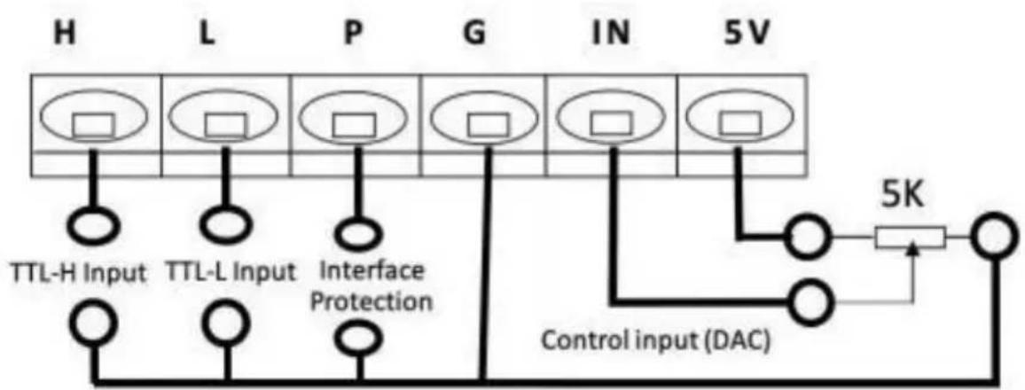
- Control Signal Input: As shown in Figure 3, the DAC signal or T signal output from the external computer are connected to the laser power supply as required, and to control laser tube output power.
- Voltage Selection: The laser power supply requires inputs of AC 100-240V, 50/60Hz.
- Additional Features: The laser power supply has a set of protective switches for protection for water flow, when the housing is opened.
Important Notes:
- The laser tube must be cooled with water when working!
- High-voltage output must not be open! (The high-voltage output positive and negative ends must be properly connected to the laser positive and negative ends).
-
The internal power supply has been designed to discharge any residual charge at shutdown, but can generally take up to two seconds. But for safety reasons you should still be careful of electric shocks! Insulation safety requirements of the suspended 40KV high voltage must be guaranteed at both ends of the high-voltage output).
-
The laser power supply must use a three-hole socket with a grou end. The case must be strictly grounded to avoid electric shock.
| The current circuit | HV+(High Voltage) |
Wiring Diagrams for Laser Power Supplies and Lasers:
flowchart
graph TD
    A["Cooling water in"] --> B["CO2 Laser"]
    B --> C["Laser output"]
    B --> D["Ammeter"]
    D --> E["Cathode"]
    E --> F["Anode"]
    F --> G["High voltage."]
    G --> H["Laser power"]
    H --> I["Machine Ground"]
    H --> J["1 2 3 4 5 6"]
    H --> K["The control end"]
    style H fill:#f9f,stroke:#333
    style I fill:#ccf,stroke:#333
    style J fill:#ccf,stroke:#333
    style K fill:#ccf,stroke:#333
flowchart
graph TD
    H["Input H"] --> TTL_H["Inverter"]
    L["Input L"] --> TTL_L["Inverter"]
    P["Input P"] --> InterfaceProtection["Interface Protection"]
    G["Input G"] --> Control["Control input (DAC)"]
    IN["Input IN"] --> Control
    5V["5V"] --> 5K["5K Resistor"]
    TTL_H --> signal_ground["signal ground"]
    TTL_L --> signal ground
    InterfaceProtection --> signal ground
    Control --> signal ground
    5K --> SignalGround["Signal Ground"]
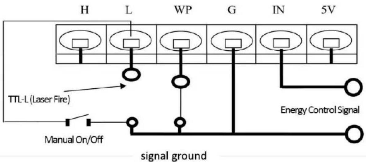
Control terminal meaning and function:
| TTL-H Input | TTL-L Input | Control Input (DAC) | Laser output |
| Open | Low (<0.3V) | 0-5V | Pmin - Pmax |
| High (>3V) | 0-5V | 0 | |
| Low (<0.3V) | Open | 0-5V | 0 |
| High (>3V) | 0-5V | Pmin - Pmax | |
| Protection Interface | 0-5V | 0 | |
Low-level TTL Signal Connection Diagram
flowchart
graph LR
    A["Cooling water in"] --> B["CO 2 Laser"]
    B --> C["Laser output"]
    D["Anode"] --> E["High voltage."]
    E --> F["Laser power"]
    G["Ammeter"] --> H["The current circuit"]
    I["Machine Ground"] --> E
    J["The control end"] --> K["1 2 3 4 5 6"]
    L["Cathode"] --> M["Ammeter"]

flowchart
graph TD
    A["Signal Ground"] --> B["TTL-L (Laser Fire)"]
    A --> C["Manual On/Off"]
    B --> D["Power Supply H L WP G IN 5V"]
    C --> E["Power Supply Manual On/Off"]
    D --> F["Output Signal"]
    E --> G["Output Signal"]
    style A fill:#f9f,stroke:#333
    style B fill:#ccf,stroke:#333
    style C fill:#cfc,stroke:#333
    style D fill:#fcc,stroke:#333
    style E fill:#cff,stroke:#333
    style F fill:#ffc,stroke:#333
    style G fill:#fcc,stroke:#333
Note: There are two ways to control energy signals:
- PWM Pulse Generator: (frequency laser) intensity from 20kHz to 50kHz, 5V air-to-air ratio.
- 0-5V Analog
High-level TTL Signal Connection Diagram:
flowchart
graph TD
    A["Cooling water in"] --> B["CO2 Laser"]
    B --> C["Laser output"]
    B --> D["Ammeter"]
    D --> E["Anode"]
    E --> F["High voltage."]
    F --> G["Laser power"]
    G --> H["Machine Ground"]
    G --> I["1 2 3 4 5 6"]
    G --> J["The control end"]
    style A fill:#f9f,stroke:#333
    style B fill:#ccf,stroke:#333
    style C fill:#cfc,stroke:#333
    style D fill:#fcc,stroke:#333
    style E fill:#cff,stroke:#333
    style F fill:#ffc,stroke:#333
    style G fill:#cfc,stroke:#333
    style H fill:#fcc,stroke:#333
    style I fill:#ffc,stroke:#333
    style J fill:#fcc,stroke:#333
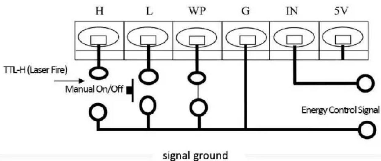
flowchart
graph TD
    A["TTL-H (Laser Fire)"] --> B["Manual On/Off"]
    B --> C["WP"]
    C --> D["G"]
    D --> E["IN"]
    E --> F["5V"]
    F --> G["Energy Control Signal"]
    style A fill:#f9f,stroke:#333
    style B fill:#ccf,stroke:#333
    style C fill:#ccf,stroke:#333
    style D fill:#ccf,stroke:#333
    style E fill:#ccf,stroke:#333
    style F fill:#ccf,stroke:#333
    style G fill:#fff,stroke:#333
Note: There are two ways to control energy signals:
- PWM pulse generator: (frequency laser) intensity from 20kHz to 505V air-to-air ratio.
- 0-5V Analog
MINGYU LASER POWER SUPPLY MODELS
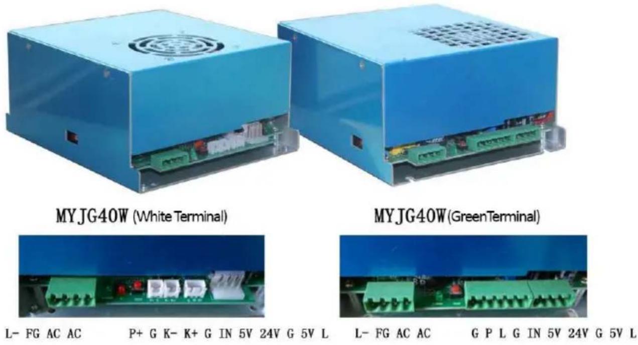
L-: Laser Tube (-) FG: Ground AC: 110V/220V
P+/P: Water Protection G: Ground
IN: Power Input 5V: Output
K-: Ground K+: Low Level
24V: Output L: Active Low
| Model Parts list picture | ||
| MYJG40W | connection terminal*3 | 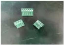 |
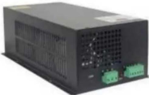
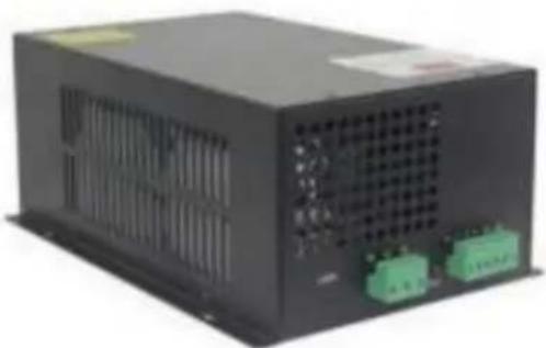
| MYJG60W/80W/100W/150W | connection terminal*2high-voltage power lines*1 | 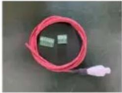 |
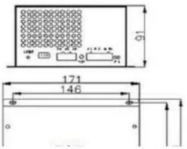
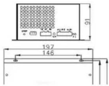
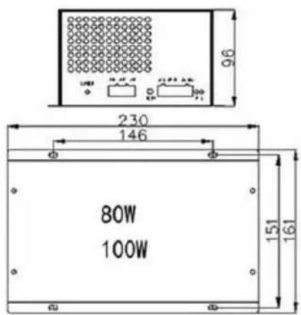
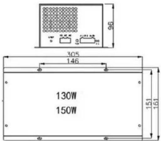
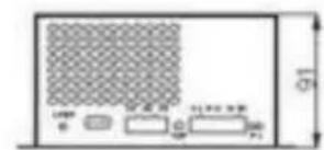
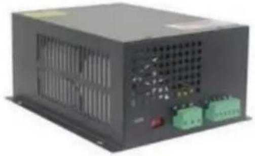
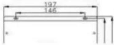
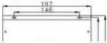
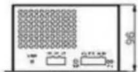
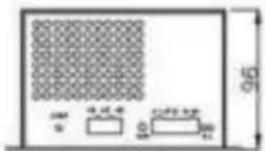
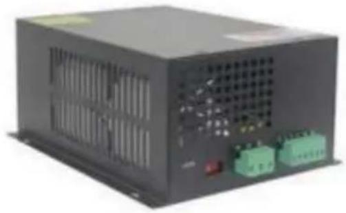
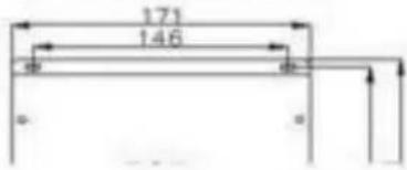
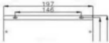
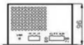
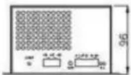
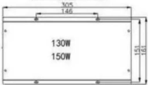
New stable laser power supply picture and mounting (size in m)
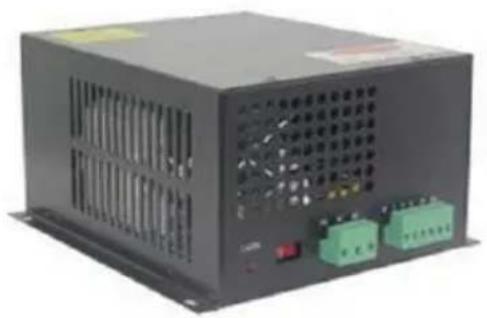
natural_image
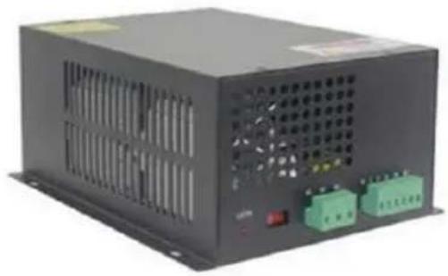
Exterior view of a black industrial power supply unit with control buttons and ventilation slots (no visible text or symbols)MYJG50W
natural_image
Exterior view of a black industrial power supply unit with ventilation slots and two green terminal blocks (no visible text or symbols)MYJG60W
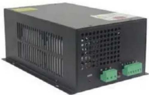
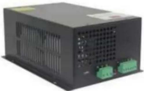
MYJG80W
MYJG130W
MYJG150W
(Customizable voltage stabilization function)
MYJG100W
(Customizable voltage stabilization function)
Laser Power Supply Main Features:
New stable laser power supply, the biggest features: the use of mod design automatic detection of laser power signal, automatic detection of water protection!
The mounting holes are all consistent and suitable for plant line insta. The use of zero-current half-bridge soft switch circuit, so that the power supply has high efficiency, fast response speed, and is easy to integrate Supports Laser tubes from various manufacturers.
Port control is simple, can use either high or low level signals. TTL can control the laser start, stop,
At the same time, there is an abnormal protection switch, to detect the outside water, ventilation and so on are functioning.
Laser power regulation can be controlled between 0 and 5V analog s or PWM signals The size of the laser power.
The power supply has an open-circuit protection function: the power s can work on the open
circuit for a short time when the protection is well grounded state, w avoids damage to the laser power supply due to the bursting of the tube.
Factory aging test: Each power supply is tested under a full load at temperature of 60 degrees, 12 hours aging test, 7 seconds, and is p on and off 500 times.
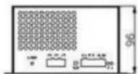
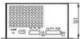
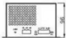
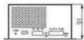
Terminal definitions, LEDs and power detection instructions:
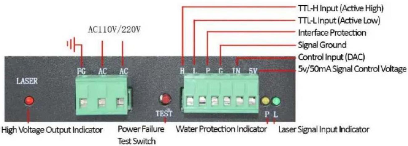
Power supply status Lights:
(LASER) Lights when Laser is Firing: If light is on and Laser Tube is fire, then laser tube is broken. If laser tube is firing, then laser power is normal.
(P) Lights when Protection circuit is functioning
(L) Lights when Test Switch is Pressed or TTL Signal is present
Technical parameters:
| Model | MYJG40W | MYJG60W | MYJG80W | MYJG100W | MYJG150W |
| Input | AC100-240V 50/60Hz | ||||
| Maximum current output | 20mA | 23mA | 25mA | 28mA | 36mA |
| Efficiency. | 91% | ||||
| Overflow protection | 130% of maximum current | ||||
| Open road protection | Yes (short time) | ||||
| Structure. | Fan Cooled | ||||
| Operating temperature | -30°C+65°C | ||||
| Relative humidity. | 20 to 85% RH (no dew) | ||||
| Insulation resistance | ≥50MΩ (DC500V) | ||||
| Vibration resistance | Amplitude 0.5mm frequency 10 to 55Hz 3D direction for 2 | ||||
| No downtime MTBF | ≥30,000hours | ||||
| Turn off the power test for 7 seconds | 500 times | ||||
Manufacturer: Shanghaimuxinmuyeyouxiangongsi
Address: Shuangchenglu 803nong11hao1602A-1609shi, baoshanqu, shanghai 200000 CN.
Imported to AUS: SIHAO PTY LTD, 1 ROKEVA STREETEASTWOOD NS 2122 Australia
Imported to USA: Sanven Technology Ltd., Suite 250, 9166 Anaheim Pla Rancho Cucamonga, CA 91730
| EC | REP |
E-CrossStu GmbH
Mainzer Landstr.69, 60329 Frankfurt am Ma
| UK | REP |
YH CONSULTING LIMITED.
C/O YH Consulting Limited Office 147, Centurion H
London Road, Staines-upon-Thames, Surrey, TW18 4
VEVOR®
TOUGH TOOLS, HALF PRICE
Technical Support and E-Warranty Certificate
www.vevor.com/support
VEVOR®
TOUGH TOOLS, HALF PRICE
Certificat www.vevor.com/support
LASER ALIMENTATION
ÉLECTRIQUE
UTILISATEUR
MANUEL
MODÈLE : MYJG 40W, MYJG 60W, MYJG
80W, MYJG 100W, MYJG 150W,
natural_image
Blue industrial electronic device with visible circuit board and ventilation grille (no text or symbols)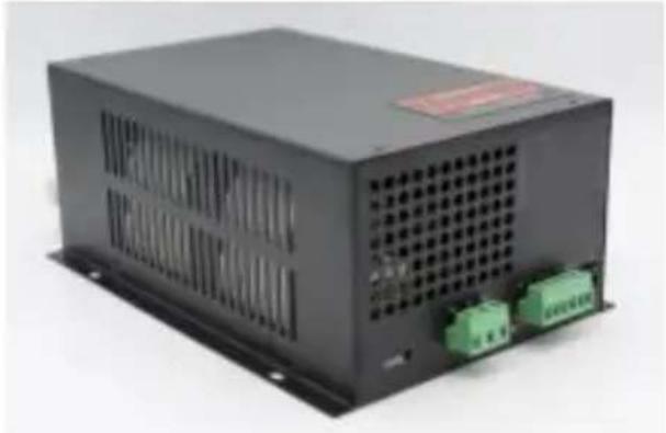
natural_image
Exterior view of a black industrial power supply unit with ventilation grille and two green terminal blocks (no visible text or symbols)MYJG 40 W MYJG 60W/80W /100W/150W
www.vevor.com/support
| The current circuit | HV+(High Voltage) |
flowchart
graph TD
    H["Input H"] --> TTL_H["Inverter"]
    L["Input L"] --> TTL_L["Inverter"]
    P["Input P"] --> InterfaceProtection["Interface Protection"]
    G["Input G"] --> ControlInput["Control Input (DAC)"]
    IN["Input IN"] --> ControlInput
    5V["5V"] --> ControlInput
    TTL_H --> ControlInput
    TTL_L --> ControlInput
    InterfaceProtection --> ControlInput
    5K["5K"] --> ControlInput
    style H fill:#f9f,stroke:#333
    style L fill:#f9f,stroke:#333
    style P fill:#f9f,stroke:#333
    style G fill:#f9f,stroke:#333
    style IN fill:#f9f,stroke:#333
    style 5V fill:#f9f,stroke:#333
    style TTL_H Input --> ControlInput
    TTL_L Input --> ControlInput
    InterfaceProtection --> ControlInput
    ControlInput --> 5K
    style 5K stroke:#000,stroke-width:2px
signal ground
flowchart
graph TD
    H["Square"] --> L["Circle"]
    L --> WP["Circle"]
    WP --> G["Square"]
    G --> IN["Square"]
    IN --> 5V["Square"]
    TtL-L["Laser Fire"] --> L
    Manual["Manual On/Off"] --> L
    L --> Signal["signal ground"]
    Signal --> Energy["Energy Control Signal"]
    Energy --> In
    Energy --> IN
    style H fill:#fff,stroke:#000
    style L fill:#fff,stroke:#000
    style WP fill:#fff,stroke:#000
    style G fill:#fff,stroke:#000
    style IN fill:#fff,stroke:#000
    style 5V fill:#fff,stroke:#000
    note right of L: TTL-L (Laser Fire)
    note right of G: Signal ground
P+/P: Water Protection G: Ground
K-: Ground
K+: Low Level
IN: Power Input 5V: Output
24V: Output
L: Active Low
| Modèle | Parties liste | image |
| MYJG40W | connexion terminal | 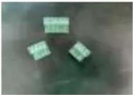 |
| MYJG60W/80W/100W/150W | connexion terminal haute tension pouv lignes*1 |  |
natural_image
Exterior view of a black industrial power supply unit with ventilation slots and terminal blocks (no visible text or symbols)MYJG50W

natural_image
Exterior view of a black industrial power supply unit with ventilation grilles and two green connectors (no visible text or labels)MYJG60W
natural_image
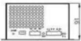
Diagram of a device rear panel with labeled ports and dimensions (no readable text or symbols)


natural_image
Exterior view of a black industrial power supply unit with ventilation slots and two green connectors (no visible text or symbols)MYJG80W
MYJG100W
(Customizable voltage stabilization function)

natural_image
Exterior view of a black industrial power supply unit with ventilation grilles and two green connectors (no visible text or symbols)MYJG130W
MYJG150W
(Customizable voltage stabilization function)

natural_image
Diagram of a server rack with grid pattern and two labeled components (no text or symbols)

natural_image
Pure electrical circuit lines without any symbols
natural_image
Blue industrial electronic device with visible circuit board and ventilation grille (no text or symbols)
natural_image
Black industrial power supply unit with ventilation grille and two green connectors (no visible text or symbols)MYJG 40 W MYJG 60W/80W /100W/150W
| The current circuit | HV+(High Voltage) |

flowchart
graph TD
    H["Input H"] --> TTL_H["Input TTL-H Input"]
    L["Input L"] --> TTL_L["Input TTL-L Input"]
    P["Input P"] --> Interface["Interface Protection"]
    G["Input G"] --> Control["Control input (DAC)"]
    IN["Input IN"] --> Control
    5V["Input 5V"] --> Control
    Control --> DAC["5K DAC"]
    DAC --> Signal["Signal Ground"]
    style H fill:#f9f,stroke:#333
    style L fill:#f9f,stroke:#333
    style P fill:#f9f,stroke:#333
    style G fill:#f9f,stroke:#333
    style IN fill:#f9f,stroke:#333
    style 5V fill:#f9f,stroke:#333
    style Control fill:#ccf,stroke:#333
    style DAC fill:#cfc,stroke:#333
    note right of Control: Control input (DAC)
    note left of Signal: signal ground
P+/P: Water Protection G: Ground
K-: Ground
K+: Low Level
IN: Power Input
5V: Output
24V: Output
L: Active Low
natural_image
Exterior view of a black industrial power supply unit with ventilation slots and terminal blocks (no visible text or symbols)MYJG50W
natural_image
Exterior view of a black industrial power supply unit with ventilation grilles and two green connectors (no visible text or symbols)MYJG60W

natural_image
Diagram of a device rear panel with labeled ports and dimensions (no readable text or symbols)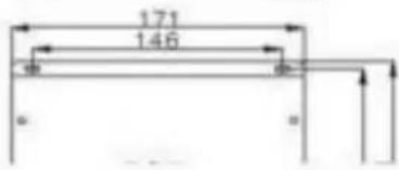


natural_image
Black industrial power supply unit with ventilation slots and two green connectors (no visible text or labels)MYJG80W
MYJG100W
(Customizable voltage stabilization function)

natural_image
Black industrial power supply unit with ventilation grilles and green terminal connectors (no visible text or symbols)MYJG130W
MYJG150W
(Customizable voltage stabilization function)
natural_image
Diagram of a server rack with grid pattern and two labeled components (no text or symbols)

natural_image
Pure electrical circuit lines without any symbols
London Road, Staines - upon - Thames, Surrey, TW
18 4 AX
VEVOR®
TOUGH TOOLS, HALF PRICE
natural_image
Blue industrial electronic device with visible circuit board and ventilation grille (no text or symbols)
natural_image
Exterior view of a black industrial power supply unit with ventilation grille and two green terminal blocks (no visible text or symbols)MYJG 40 W Potenza 60W/80W /100W/150W
www.vevor.com/support
| The current circuit | HV+(High Voltage) |
flowchart
graph TD
    H["Input H"] --> TTL_H["Input TTL-H Input"]
    L["Input L"] --> TTL_L["Input TTL-L Input"]
    P["Input P"] --> Interface["Interface Protection"]
    G["Input G"] --> Control["Control input (DAC)"]
    IN["Input IN"] --> Control
    5V["Input 5V"] --> Control
    Control --> DAC["5K DAC"]
    DAC --> Signal["Signal Ground"]
    style H fill:#f9f,stroke:#333
    style L fill:#f9f,stroke:#333
    style P fill:#f9f,stroke:#333
    style G fill:#f9f,stroke:#333
    style IN fill:#f9f,stroke:#333
    style 5V fill:#f9f,stroke:#333
    style Control fill:#ccf,stroke:#333
    style DAC fill:#cfc,stroke:#333
    note right of Control: Control input (DAC)
    note left of Signal: signal ground
P+/P: Water Protection G: Ground
K-: Ground
K+: Low Level
IN: Power Input
5V: Output
24V: Output
L: Active Low
natural_image
Exterior view of a black industrial power supply unit with ventilation slots and terminal blocks (no visible text or symbols)MYJG50W

natural_image
Exterior view of a black industrial power supply unit with ventilation grilles and two green connectors (no visible text or labels)MYJG60W

natural_image
Diagram of a device rear panel with labeled ports and dimensions (no readable text or symbols)


natural_image
Black industrial power supply unit with ventilation slots and two green connectors (no visible text or labels)MYJG80W
MYJG100W
(Customizable voltage stabilization function)
natural_image
Black industrial power supply unit with ventilation grilles and green terminal connectors (no visible text or symbols)MYJG130W
MYJG150W
(Customizable voltage stabilization function)

natural_image
Diagram of a server rack with grid pattern and two labeled components (no text or symbols)
natural_image
Pure electrical circuit lines without any symbols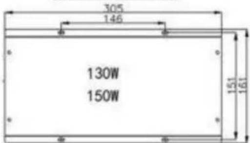
Importato in AUS: SIHAO PTY LTD, 1 ROKEVA STRADA ESTWOOD
Nuovo Galles del Sud 2122 Australia
natural_image
Blue industrial electronic device with visible circuit board and ventilation grille (no text or symbols)
natural_image
Black industrial power supply unit with ventilation slots and two green terminal blocks (no visible text or symbols)MYJG 40W MYJG 60W/80W /100W/150W
www.vevor.com/support
[Non-Text]
[Non-Text]
[Non-Text]
[Non-Text]
[Non-Text]
[Non-Text]
[Non-Text]
[Non-Text]
[Non-Text]
[Non-Text]
[Non-Text]
[Non-Text]
[Non-Text]
[Non-Text]
[Non-Text]
[Non-Text]
[Non-Text]
[Non-Text]
[Non-Text]
[Non-Text]
[Non-Text]
[Non-Text]
[Non-Text]
[Non-Text]
[Non-Text]
[Non-Text]
[Non-Text]
[Non-Text]
[Non-Text]
[Non-Text]
[Non-Text]
[Non-Text]
[Non-Text]
[Non-Text]
[Non-Text]
[Non-Text]
[Non-Text]
[Non-Text]
[Non-Text]
[Non-Text]
[Non-Text]
[Non-Text]
- 1 -
[Non-Text]
[Non-Text]
[Non-Text]
[Non-Text]
[Non-Text]
[Non-Text]
[Non-Text]
[Non-Text]
[Non-Text]
[Non-Text]
[Non-Text]
[Non-Text]
[Non-Text]
[Non-Text]
[Non-Text]
[Non-Text]
[Non-Text]
[Non-Text]
[Non-Text]
[Non-Text]
[Non-Text]
[Non-Text]
[Non-Text]
[Non-Text]
[Non-Text]
[Non-Text]
[Non-Text]
[Non-Text]
[Non-Text]
[Non-Text]
[Non-Text]
[Non-Text]
[Non-Text]
[Non-Text]
[Non-Text]
[Non-Text]
[Non-Text]
[Non-Text]
[Non-Text]
[Non-Text]
- 1 -
| The current circuit | HV+(High Voltage) |

flowchart
graph TD
    H["Input H"] --> TTL_H["Input TTL-H Input"]
    L["Input L"] --> TTL_L["Input TTL-L Input"]
    P["Input P"] --> Interface["Interface Protection"]
    G["Input G"] --> Control["Control input (DAC)"]
    IN["Input IN"] --> Control
    5V["Input 5V"] --> Control
    Control --> DAC["5K DAC"]
    DAC --> Signal["Signal Ground"]
    style H fill:#f9f,stroke:#333
    style L fill:#f9f,stroke:#333
    style P fill:#f9f,stroke:#333
    style G fill:#f9f,stroke:#333
    style IN fill:#f9f,stroke:#333
    style 5V fill:#f9f,stroke:#333
    style Control fill:#ccf,stroke:#333
    style DAC fill:#ccf,stroke:#333
    note right of Control: Control input (DAC)
    note left of Signal: signal ground
P+/P: Water Protection G: Ground
K-: Ground
K+: Low Level
IN: Power Input 5V: Output
24V: Output
L: Active Low
natural_image
Exterior view of a black industrial power supply unit with ventilation slots and terminal blocks (no visible text or symbols)MYJG50W
natural_image
Exterior view of a black industrial power supply unit with ventilation grilles and terminal blocks (no visible text or symbols)MYJG60W

natural_image
Diagram of a device front panel with grid pattern and labeled ports (no readable text or symbols)
natural_image
Exterior view of a black industrial power supply unit with ventilation slots and two green connectors (no visible text or symbols)MYJG80W
MYJG100W
(Customizable voltage stabilization function)

natural_image
Exterior view of a black industrial power supply unit with ventilation grilles and two green connectors (no visible text or symbols)MYJG130W
MYJG150W
(Customizable voltage stabilization function)

natural_image
Diagram of a server rack with grid pattern and two labeled components (no text or symbols)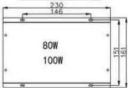

natural_image
Pure electrical circuit lines without any symbols
natural_image
Blue industrial electronic device with visible circuit board and ventilation grille (no text or symbols)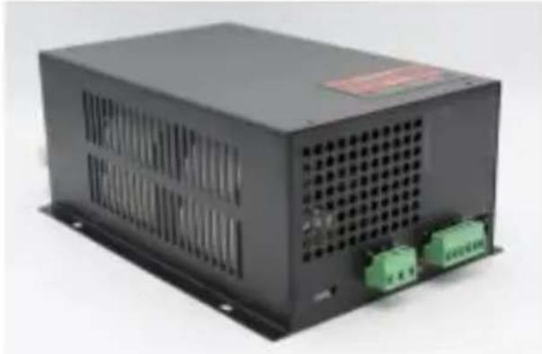
natural_image
Black industrial power supply unit with ventilation grille and two green terminal blocks (no visible text or symbols)MYJG 40 W MYJG 60W/80W /100W/150W
| The current circuit | HV+(High Voltage) |

flowchart
graph TD
    H["Input H"] --> TTL_H["Input TTL-H Input"]
    L["Input L"] --> TTL_L["Input TTL-L Input"]
    P["Input P"] --> Interface["Interface Protection"]
    G["Input G"] --> Control["Control input (DAC)"]
    IN["Input IN"] --> Control
    5V["Input 5V"] --> Control
    Control --> DAC["5K DAC"]
    DAC --> Signal["Signal Ground"]
    style H fill:#f9f,stroke:#333
    style L fill:#f9f,stroke:#333
    style P fill:#f9f,stroke:#333
    style G fill:#f9f,stroke:#333
    style IN fill:#f9f,stroke:#333
    style 5V fill:#f9f,stroke:#333
    style Control fill:#ccf,stroke:#333
    style DAC fill:#cfc,stroke:#333
    note right of Control: Control input (DAC)
    note left of Signal: signal ground
P+/P: Water Protection G: Ground
K-: Ground
K+: Low Level
IN: Power Input
5V: Output
24V: Output
L: Active Low
natural_image
Exterior view of a black industrial power supply unit with ventilation slots and control buttons (no visible text or symbols)MYJG50W

natural_image
Exterior view of a black industrial power supply unit with ventilation slots and two green connectors (no visible text or labels)MYJG60W


natural_image
Exterior view of a black industrial power supply unit with ventilation slots and two green terminal blocks (no visible text or symbols)MYJG80W
MYJG100W
(Customizable voltage stabilization function)

natural_image
Exterior view of a black industrial power supply unit with ventilation grilles and two green connectors (no visible text or symbols)MYJG130W
MYJG150W
(Customizable voltage stabilization function)
natural_image
Diagram of a grid-patterned panel with labeled dimensions (no text or symbols)
natural_image
Pure electrical circuit lines without any symbols
natural_image
Blue industrial electronic device with visible circuit board and ventilation grille (no text or symbols)
natural_image
Black rectangular electronic power supply unit with ventilation grille and two green terminal blocks (no visible text or symbols)MIJNJG 40 W MIJNJG 60W/80W /100W/150W
BEHOEFTE HULP? CONTACT ONS!
| The current circuit | HV+(High Voltage) |

flowchart
graph TD
    H["Input H"] --> TTL_H["Input TTL-H Input"]
    L["Input L"] --> TTL_L["Input TTL-L Input"]
    P["Input P"] --> Interface["Interface Protection"]
    G["Input G"] --> Control["Control input (DAC)"]
    IN["Input IN"] --> Control
    5V["Input 5V"] --> Control
    Control --> DAC["5K DAC"]
    DAC --> Signal["Signal Ground"]
    style H fill:#f9f,stroke:#333
    style L fill:#f9f,stroke:#333
    style P fill:#f9f,stroke:#333
    style G fill:#f9f,stroke:#333
    style IN fill:#f9f,stroke:#333
    style 5V fill:#f9f,stroke:#333
    style Control fill:#ccf,stroke:#333
    style DAC fill:#ccf,stroke:#333
    note right of Control: Control input (DAC)
    note left of Signal: signal ground
P+/P: Water Protection G: Ground
K-: Ground
K+: Low Level
IN: Power Input
5V: Output
24V: Output
L: Active Low
natural_image
Exterior view of a black industrial power supply unit with ventilation slots and control buttons (no visible text or symbols)MYJG50W
natural_image
Exterior view of a black industrial power supply unit with ventilation slots and two green connectors (no visible text or labels)MYJG60W


natural_image
Exterior view of a black industrial power supply unit with ventilation slots and two green terminal blocks (no visible text or symbols)MYJG80W
MYJG100W
(Customizable voltage stabilization function)
natural_image
Exterior view of a black industrial power supply unit with ventilation grilles and two green connectors (no visible text or symbols)MYJG130W
MYJG150W
(Customizable voltage stabilization function)
natural_image
Diagram of a device layout with grid pattern and labeled components (no readable text or symbols)
certificaat ate www.vevor.com/support
VEVOR®
TOUGH TOOLS, HALF PRICE
www.vevor.com/support
LASER STRÖMFÖRSÖRJNING ANVÄNDARE MANUELL
MODELL : MYJG 40W, MYJG 60W, MYJG 80W, MYJG 100W, MYJG 150W,
natural_image
Blue industrial electronic device with visible circuit board and ventilation grille (no text or symbols)
natural_image
Exterior view of a black industrial power supply unit with ventilation grille and two green terminal blocks (no visible text or symbols)MYJG 40 W MYJG 60W/80W /100W/150W
| The current circuit | HV+(High Voltage) |
P+/P: Water Protection G: Ground
K-: Ground
K+: Low Level
IN: Power Input
5V: Output
24V: Output
L: Active Low
natural_image
Exterior view of a black industrial power supply unit with ventilation slots and control buttons (no visible text or symbols)MYJG50W

natural_image
Exterior view of a black industrial power supply unit with ventilation slots and two green connectors (no visible text or labels)MYJG60W
natural_image
Front view of a device with a grid pattern and labeled ports (no readable text or symbols)


natural_image
Exterior view of a black industrial power supply unit with ventilation slots and two green terminal blocks (no visible text or symbols)MYJG80W
MYJG100W
(Customizable voltage stabilization function)

natural_image
Exterior view of a black industrial power supply unit with ventilation grilles and two green connectors (no visible text or symbols)MYJG130W
MYJG150W
(Customizable voltage stabilization function)

natural_image
Diagram of a device layout with grid pattern and labeled components (no readable text or symbols)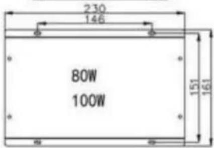


Place, Rancho Cucamonga, CA 91730
| EC | REP |
E- CrossStu GmbH
Centurion House, London Road, Staines - upon -
Thames, Surrey, TW 18 4 AX