JH-1B - Microscope Vevor - Free user manual and instructions
Find the device manual for free JH-1B Vevor in PDF.

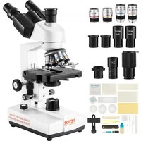
| Product Type | Multidirectional Stereoscopic Microscope |
| Brand | Vevor |
| Model | JH-1B |
| Eyepiece Magnification | 10X |
| Objective Lens Magnification Range | 0.7X - 4.5X |
| Total Magnification | 7X - 45X |
| Interpupillary Range | 50 - 75 mm |
| Working Distance | 0 - 400 mm |
| Objective Mounting Diameter | Φ77 ± 0.5 mm |
| Lighting | LED Light Ring, DC 5V Input (USB) |
| Lighting Power Supply | USB 5V |
| Included Accessories | 3-inch Ball Vise, Vise Base, Set of Clamping Heads, 2 Eyepieces, 2 Objectives, Eyecups, Dust Cover, Wrenches, Bolts |
| Color | Black |
| Main Material | Metal and Plastic |
| Maintenance | Clean with a soft cloth; avoid moisture, dust, and shocks |
| Safety | Use protective equipment; keep out of reach of children |
| Available Spare Parts | Replacement kits for vise (DZQ-627, DZQ-628), locking pin (DZQ-046) |
| Compliance | FCC Part 15, European Directive 2012/19/EU (WEEE) |
Frequently Asked Questions - JH-1B Vevor
User questions about JH-1B Vevor
0 question about this device. Answer the ones you know or ask your own.
Ask a new question about this device
Download the instructions for your Microscope in PDF format for free! Find your manual JH-1B - Vevor and take your electronic device back in hand. On this page are published all the documents necessary for the use of your device. JH-1B by Vevor.
USER MANUAL JH-1B Vevor
Technical Support and E-Warranty Certificate www.vevor.com/support
MULTI-DIRECTIONAL MICROSCOPE MODEL:JH-1A/JH-1B
We continue to be committed to provide you tools with competitive price. "Save Half", "Half Price" or any other similar expressions used by us only represent of savings you might benefit from buying certain tools with us compared to top brands and does not necessarily mean to cover all categories of tools offered are kindly reminded to verify carefully when you are placing an order with us actually saving half in comparison with the top major brands.
VEVOR®
TOUGH TOOLS, HALF PRICE
MULTI-DIRECTIONAL MICROSCOPE
MODEL:JH-1A/JH-1B

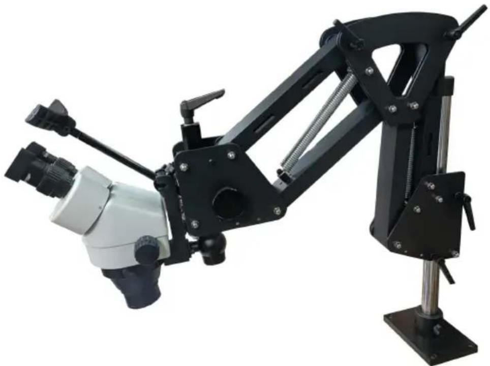
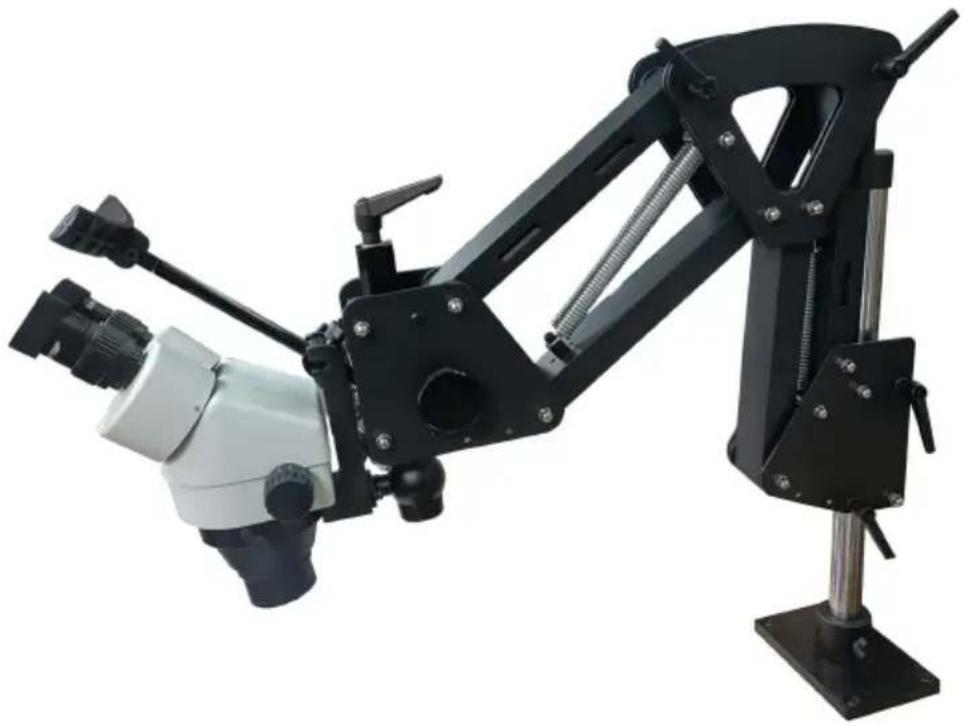
natural_image
Black and white mechanical arm with adjustable arms and a mounted base (no visible text or symbols)NOTE: The actual product you receive determines its look.
NEED HELP? CONTACT US!
Have product questions? Need technical support? Please feel fr contact us:
Technical Support and E-Warranty Certificate www.vevor.com/support
This is the original instruction, please read all manual instruction carefully before operating. VEVOR reserves a clear interpretation user manual. The appearance of the product shall be subject to product you received. Please forgive us that we won't inform you there are any technology or software updates on our product.
 | Warning - To reduce the risk of injury, user must read instr manual carefully. |
 | CORRECT DISPOSALThis product is subject to the provision of european Directive 2012/19/EU. The symbol showing a wheelie bin crossed through indicates that the product requires separate refuse collection in European Union. This applies to the product and all accessor marked with this symbol. Products marked as such may not discarded with normal domestic waste, but must be taken to acollection point for recycling electrical and electronic devices. |

WARNING!
- Use the product only after receiving training.
- Wear necessary personal protective equipment such as protective gloves during use.
- Ensure that the workspace remains clean, dry, and well-ventilated during operation.
- Keep away from children and read this manual in detail before use.
FCC Information
CAUTION: Changes or modifications not expressly approved by the party responsible for compliance could void the user's authority to operate the equipment!
This device complies with Part 15 of the FCC Rules. Operation is subject to following two conditions:
1) This product may cause harmful interference.
2) This product must accept any interference received, including interference that may cause undesired operation.
WARNING: Changes or modifications to this product not expressly approved by the party responsible for compliance could void the user's authority to operate product.
Note: This product has been tested and found to comply with the limits for B digital device pursuant to Part 15 of the FCC Rules. These limits are desired to provide reasonable protection against harmful interference in a residential installation.
This product generates, uses and can radiate radio frequency energy, and if installed and used in accordance with the instructions, may cause harmful interference to radio communications. However, there is no guarantee that interference will not occur in a particular installation. If this product does cause harmful interference to radio or television reception, which can be determined by turning the product off and on, the user is encouraged to try to correct the interference by one or more of the following measures.
- Reorient or relocate the receiving antenna.
- Increase the distance between the product and receiver.
- Connect the product to an outlet on a circuit different from that to which receiver is connected.
- Consult the dealer or an experienced radio/TV technician for assistance.
SAVE THESE INSTRUCTIONS
MODEL AND PARAMETERS
| Model | JH-1A | JH-1B |
| Magnification of eyepiece | 10X | 10X |
| Magnification of objective | 0.7X-4.5X | 0.7X-4.5X |
| Total Magnification | 7X-45X | 7X-45X |
| Interpupillary range | 50-75mm | 50-75mm |
| Lens mount hole | Φ77±0.5mm | Φ77±0.5mm |
| Working distance | 0-400mm | 0-400mm |
| Led Ring Light | Input:DC5V(USB) | Input:DC5V(USB) |
| 3inch Ball Vise | x | √ |
| Ball vise base | x | √ (Plastic) |
| Clamp head set | x | √ |
| Color | Black | |
NOTE: Please refer to the model you purchased to determine the parameters
STRUCTURE DIAGRAM
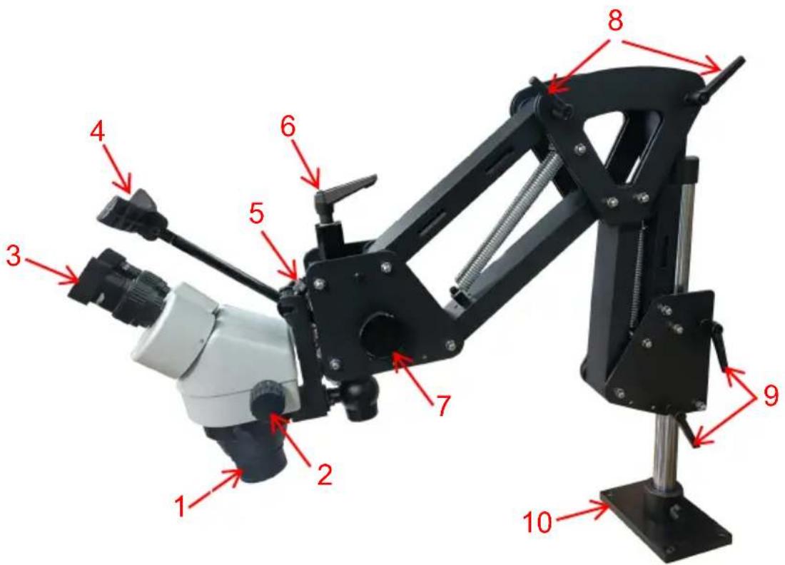
1.Objective lens 2.Objective magnification adjustment 3.Eyepiece 4.Headrest 5.Headrest adjustment 6.Object lens Angle adjustment 7.Focal length adjustment 8.Support extension adjustment 9.Height control 10.Base
PARTS LIST
| Image | Item/Qty | Image | Item/Qty | |
 | Microscope Head x | 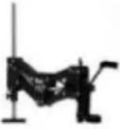 | Spring Bracket x1 | |
 | MicroscopeHolderx 1 | 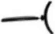 | Headrest x1 | |
 | Eyepiece x2 |  | Objective Lens x2 | |
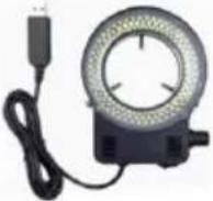 | LED Ring Light x1 | 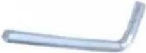 | Wrench x1(Only JH-1B has it.) | |
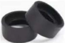 | Eye shield x2 | 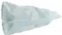 | Dust cover x1 | |
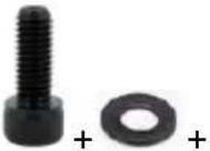 | Bolts x4(To fix the base plateon the desk) | 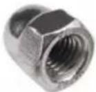 | Cap Nut x1(Multiple, used for replacement) | |
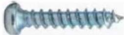 | Bolts x4 (To fix th base plateau the wood desk) | 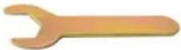 | 8mm Wrench x1 | |
 | 3inch Ball Vise x1(Only JH-1B has it.) |  | Ball vise base x1(Only JH-1B has it.) | |
 | Clamp head set x1(Only JH-1B has it.) |  | User manual x1 |
INSTALLATION
1. Install Ring /Bracket Assembly
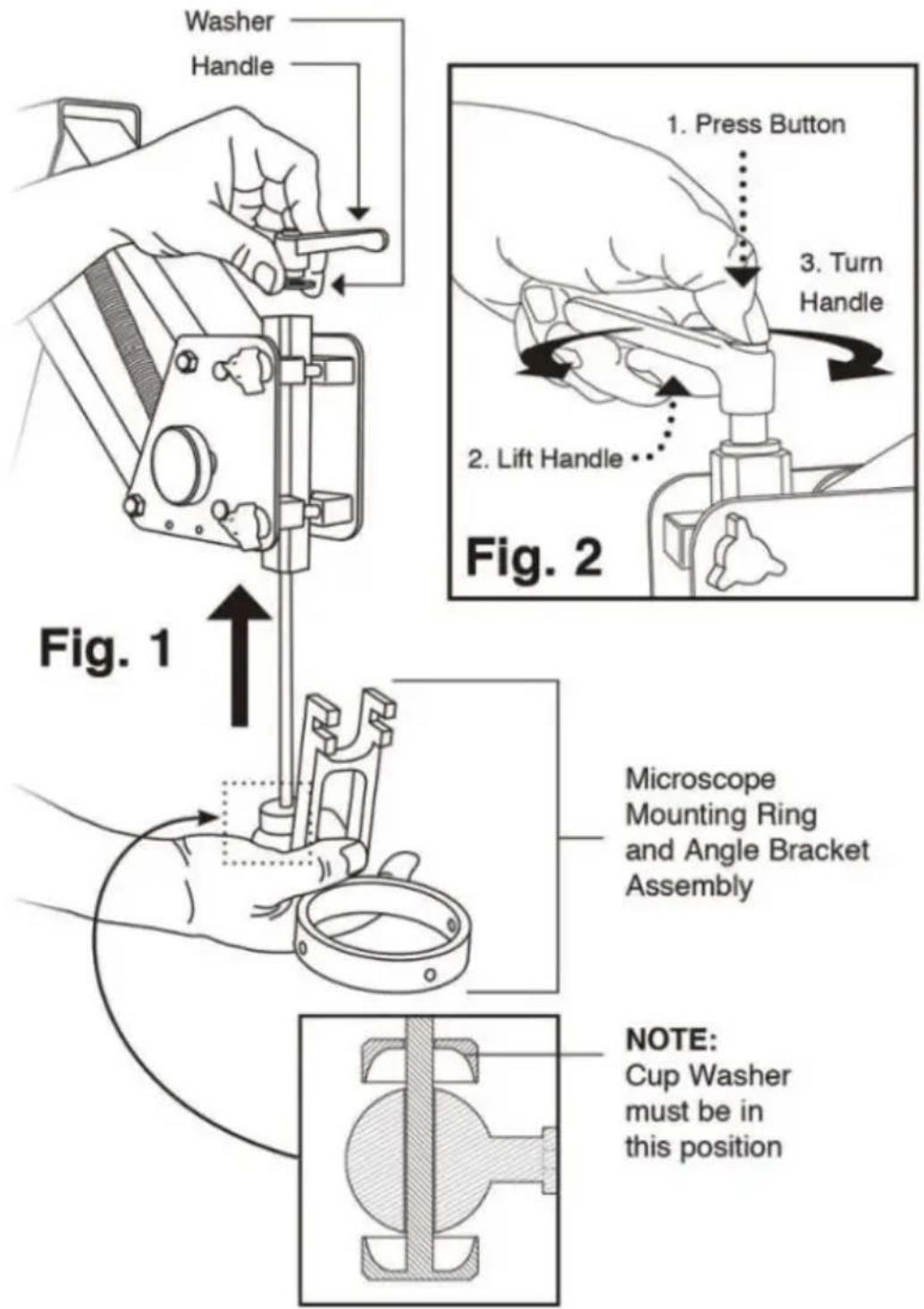
·(Fig.1) Insert the rod into the bottom of the mounting post, then attach handl
- Make sure the washer is under handle.
- Position handle away from stand arm by lifting the handle while pressing the center button.
(Fig.2) This does not loosen the handle. To attach the stand to your work to see microscope Stand Base Template (page 3). The microscope body sets in the ring and is secured by three thumb screws, included.
2. Install Headrest

After installing the microscope, attach the headrest
(Fig.3) Make sure white nylon washer is between the T-Knob and the headrest mount. Adjust the angle using the side T-Knob; adjust depth using the top t-knob. The forehead end may also be adjusted.
3. Setup and Operation
After the stand is secured to the bench top there are many choices for adjustments to fit your needs. Turn tension knobs clockwise to add friction, counter-clockwise to reduce friction.
A.Controls front arm.Tension knob.
B. Controls friction during movement of back arm. Tension knob.
C.Controls angle of microscope on pivot ball. Loosen to adjust.
D. Adjusts focus. Tension knob.
E. Locks arm height on the stand rod.
F.Controls the drag of the arm swing.
G. Tighten for additional arm rigidity.
4. For Wood Top Benches
Decide where to locate the microscope stand on your bench top.Make sure it is plenty of "reach"so the microscope is over your work.Using the template below,tape it exactly where the base will be located.With a center punch or mark the centers of the screw holes through the paper and into the bench top.Remove the template and drill a starter hole for the screws using a 1/8" bit.Drill all four holes a little more than 1"deep.Hold the drill as square to the surface as possible.Attach the stand to the bench with the 1-1/2"wood screws are included in the package.Be sure to tighten the screws so that the heads tight against the metal base.If you are having trouble setting the screws you probably did not drill the holes deep enough.
5. For Metal Top Benches
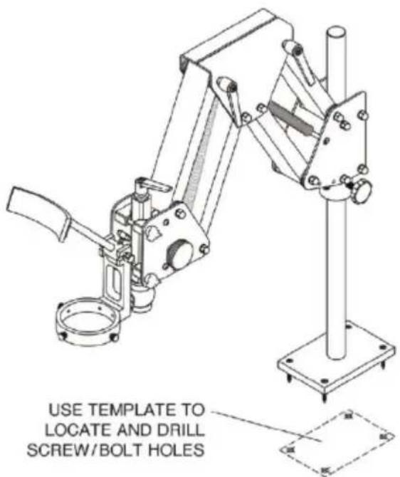
It is advisable to use 10-32 flat head bolts (not included) with a length of ab 1/2" more than the thickness of your bench top. Use the template below as described above to locate the centers and drill 1/4" holes through the bench top. Bolt the stand down using washers and nuts on the underside. If the be top is made of a sheet metal with a lightweight substrate we recommend ad board or metal plate to the underside for extra strength.
6. Adjust the specimen slide
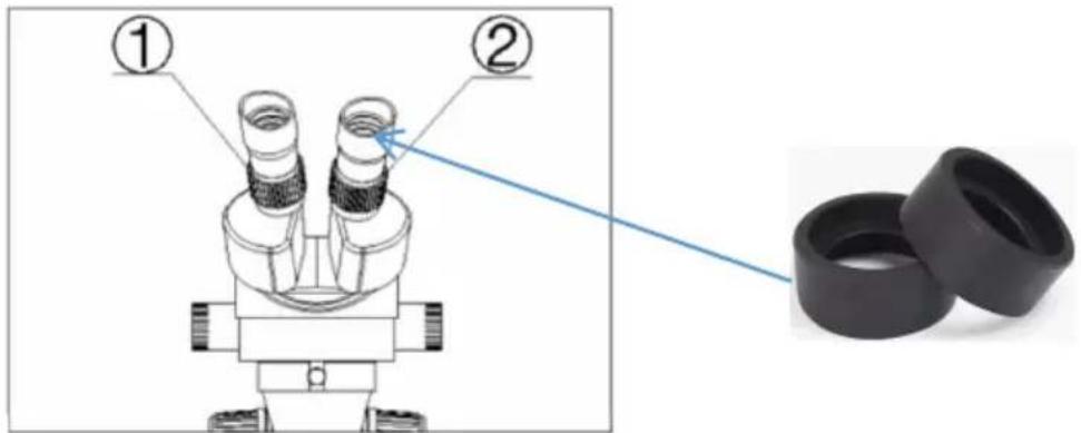
Fig. 4
1) Turn the zoom control knob to the maximum magnification.
2) Turn the diopter adjusting rings to the zero.
3) Observe the specimen through the right eyepiece and make the image cle by turning the focusing knob.
Fig.4 5) Rotate the zoom control knob to the minimum magnification.
4) Observe the specimen through the right eyepiece and make the image cle
by turning the right diopter adjusting ring②.(Fig.3)
5) Redo the step(1),(3),(4)and (5)till the right adjusting ring is more precise.
6) Do the step (4) and make the image clear which is observed through the eyepiece by turning the left diopter adjusting ring①.(Fig.4)
NOTE:
- User could adjust the height distance between the micro-scope and the ok to about 165mm to get a better clear picture.(If it's not clear,adjust the height according to your multiplier need.)
- Install the eye shields for eye comfort.
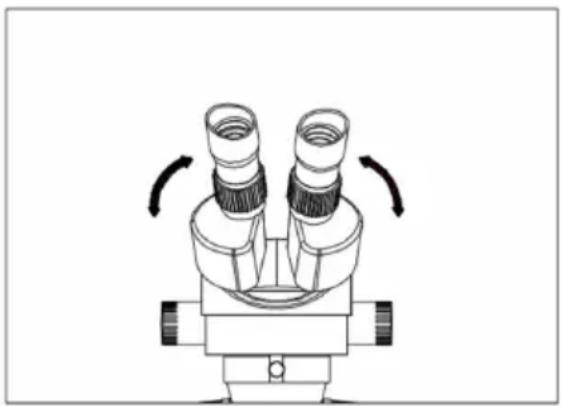
7. Adjust the interpupillary distance
Adjust the prism housing along the direction of arrow-head of the Fig.5 till the observation is comfortable.
natural_image
Diagram of a microscope with two lenses and directional arrows indicating rotation (no text or labels)Fig.5
CLEAN AND CARE RULES
- After using the microscope, put on a dust cover.
- Check the setting screws regularly.
- Keep the environment around the microscope free from moisture, dust and ventilation.
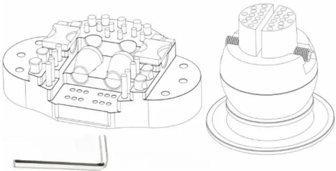
STANDARD BLOCK BALL VISE USER MANUAL
natural_image
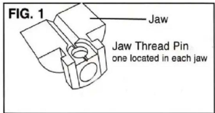
Technical line drawing of a mechanical component with internal cavities and mounting base (no text or symbols)Vise Jaw Thread Replacement · DZQ-627 & DZQ-628
Over tightening the jaws will cause wear and damage to the threads. If jaws become loose, replace with kit DZQ-627. Remove the jaws by opening them wide as possible until they come off the end of the jaw screw (FIG.1) The thread pin is located on the under side of each jaw. NOTE: Before removing locate the on with the "L"This is the left hand thread pin and will need to re with same. Apply a small amount of grease (included in kit) to the O-rings screw before installing them. Lift the jaw screw out of the yoke that it rotates and replace it. Note which side the left hand thread is on. Grease the thread yoke well.
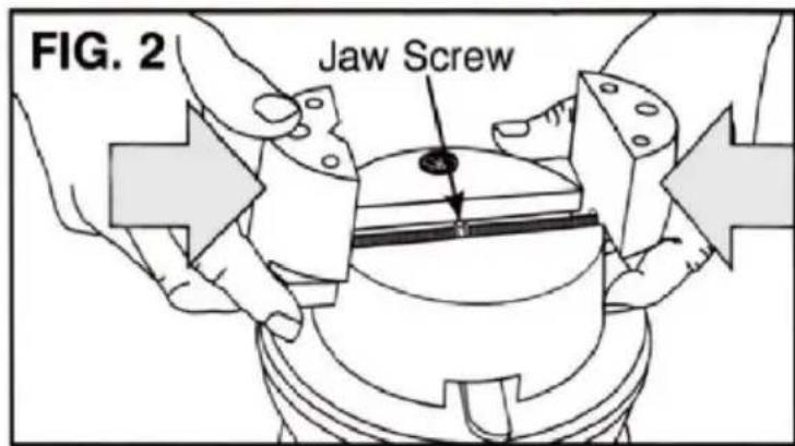
Now, the hard part: you must start the jaws threads at the same time when replacing them( FIG. 2). Hold each jaw in position and turn the jaw screw to close them. Either a large rubber band or a second person is useful to help the jaw screw while you hold the jaws against the thread. If the jaws don't the same time in the center, remove them and try starting the threads at the time again.
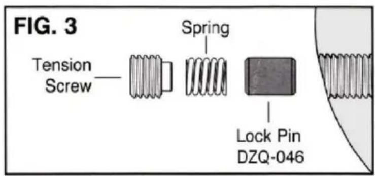
Rotational Lock Replacement
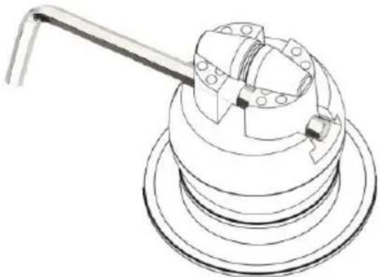
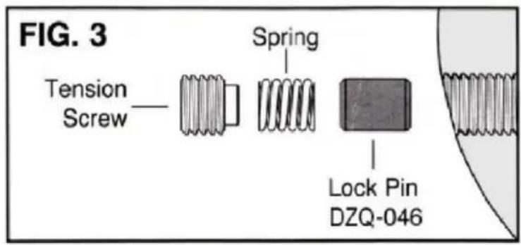
The LOCK or DRAG PIN is subject to much wear and may need to be rep after extended use. Simply remove the ball swivel tension screw with the he
wrench. The spring and Lock Pin should follow (FIG. 3) if not, turn the ball they fall out. Replace the Lock Pin (DZQ-046), Spring, and Tension Screw.
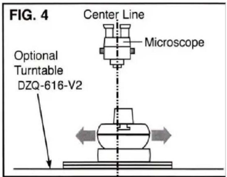
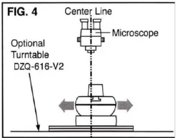
Turntable Base For Microscope Work · DZQ-616-V2
To use the Turntable Base, lock the vise by tightening the swivel tension sc until the ball will not turn. The turntable now becomes your rotation, allowing to adjust the work's center of rotation into the field of view of the microscope the center of the turntable with the center of the microscope view (FIG. 4). Change working views by repositioning the vise.
Thread Pin Replacement Kit · DZQ-627
(Not Shown). Includes Jaw Screw, Left and Right Thread Pins, O-Rings, and of Grease.


INSTRUCTION
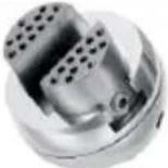
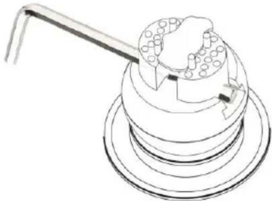
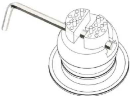
With a variety of pins that fit the upper jaw plates of very block, users can instantly solve work holding problems and start working sooner. Includes 8 sn pins, 4 flat square pins, 2 rectangular inset-curve pins, 4 thick round inset pins, rubber-coated pins, and 2 leather-faced ring clamp pins in molded base.
| PART | DESCRIPTION | QTY |
| 1 | Ring clamp assembly | 2 |
| 2 | Attachment plate #2 assembly | 2 |
| 3 | Attachment plate #3 assembly | 4 |
| 4 | Attachment plate #4 assembly | 4 |
| 5 | Attachment pin #5 assembly (short) | 4 |
| 6 | Attachment pin #6 assembly (long) | 4 |
| 7 | Formed complete attachment pin #7 | 8 |
Ring clamp assembly
The leather helps to protect the things to keep it for getting damaged, such as gold, etc. (USED THESE PADS FOR WHATEVER DON'T WANT TO OR DAMA(PIECE)
natural_image
Technical line drawing of a mechanical component with a lever and base (no text or symbols)Long & Short Pins
This Pins also have a little rubber pieces on them which will also help protect the work. The long pins is to protect thicker piece.
natural_image
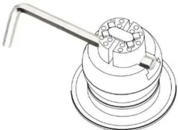
Line drawing of a mechanical component with a tool and circular base (no text or symbols)8 Little Pins
This Pins is helps to holds something that kind of weird shape,or not a typi square or circle.Place them in multiple spots throughout these plates
natural_image
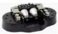
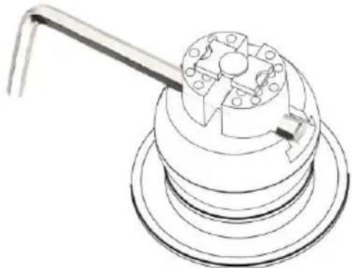
Technical line drawing of a mechanical component with a lever and base (no text or symbols)Pin Plates
These pin plates have little divots in them for circular and square pieces, ma perfect for coins or rings any thing smaller circle
natural_image
Technical line drawing of a mechanical device with a handle and internal components (no text or symbols)Small Plates
These plates have divots in them right along on the edge also have straightWorking on straight side or use the side with the divots to kind of catch th
natural_image
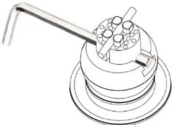
Technical line drawing of a mechanical device with a tool and circular components (no text or symbols)Round Radius pins
This one is good option for work on cylindrical things, like pen or a scribe, everything is small round cylindrical these are a good option for.
natural_image
Technical line drawing of a mechanical component with a handle and central hub (no text or symbols)VEVOR®
TOUGH TOOLS, HALF PRICE
Technical Support and E-Warranty Certificate
www.vevor.com/support
VEVOR®
TOUGH TOOLS, HALF PRICE
Technisch Ondersteuning en e-garantiecertificaat www.vevor.com/support
MULTIDIRECTIONELE MICROSCOOP
MODEL: JH-1A/JH-1B
We continue to be committed to provide you tools with competitive price. "Save Half", "Half Price" or any other similar expressions used by us only represent of savings you might benefit from buying certain tools with us compared to top brands and does not necessarily mean to cover all categories of tools offered are kindly reminded to verify carefully when you are placing an order with us actually saving half in comparison with the top major brands.
VEVOR®
TOUGH TOOLS, HALF PRICE
MULTI-DIRECTIONAL
MICROSCOPE
MODEL: JH-1A /JH-1B
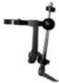
natural_image
Mechanical robotic arm with articulated joints and a mounted base (no visible text or symbols)NEED HELP? CONTACT US!
Have product questions? Need technical support? Please feel fr contact us:
Technical Support and E-Warranty Certificate www.vevor.com/support
This is the original instruction, please read all manual instruction carefully before operating. VEVOR reserves a clear interpretation user manual. The appearance of the product shall be subject to product you received. Please forgive us that we won't inform you there are any technology or software updates on our product.
SAFETY INSTRUCTIONS
Fig. 4
natural_image
Diagram of a microscope with two lenses and directional arrows indicating rotation (no text or labels)Fig.5
CLEAN AND CARE RULES
natural_image
Technical line drawings of a mechanical component, showing cross-sectional and top views (no text or symbols)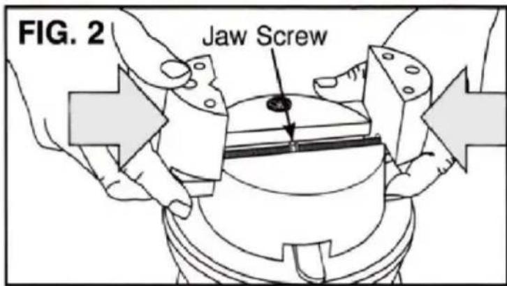


INSTRUCTION
| DEEL | BESCHRIJVING | AANTAL |
| 1 | Montage ringklem | 2 |
| 2 | Bevestigingsplaat # 2 montage | 2 |
| 3 | Bevestigingsplaat # 3 montage | 4 |
| 4 | Bevestigingsplaat # 4 montage | 4 |
| 5 | Bevestigingspin # 5 montage (kort) | 4 |
| 6 | Bevestigingspin # 6 montage (lang) | 4 |
| 7 | Gevormde complete bevestigingspin # 7 | 8 |
Montage ringklem
natural_image
Technical line drawing of a mechanical component with a handle and mounting base (no text or symbols)natural_image
Line drawing of a mechanical component with a tool and circular base (no text or symbols)8 kleine spelden
natural_image
Technical line drawing of a mechanical component with a lever and base (no text or symbols)Pinplaten
natural_image
Technical line drawing of a mechanical device with a handle and internal components (no text or symbols)Kleine Borden
natural_image
Technical line drawing of a mechanical device with a tool and circular components (no text or symbols)Ronde straalpennen
natural_image
Technical line drawing of a mechanical component with a handle and circular base (no text or symbols)VEVOR®
TOUGH TOOLS, HALF PRICE
www.vevor.com/support
VEVOR®
TOUGH TOOLS, HALF PRICE
We continue to be committed to provide you tools with competitive price. "Save Half", "Half Price" or any other similar expressions used by us only represent estimate of savings you might benefit from buying certain tools with us compared top brands and does not necessarily mean to cover all categories of tools offered are kindly reminded to verify carefully when you are placing an order with us actually saving half in comparison with the top major brands.
VEVOR®
TOUGH TOOLS, HALF PRICE
MULTI-DIRECTIONAL MICROSCOPE
MODÈLE : JH-1A /JH-1B

natural_image
Mechanical robotic arm with articulated joints and a mounted base (no visible text or symbols)NEED HELP? CONTACT US!
Have product questions? Need technical support? Please feel from contact us:
Technical Support and E-Warranty Certificate www.vevor.com/support
This is the original instruction, please read all manual instruction carefully before operating. VEVOR reserves a clear interpretation user manual. The appearance of the product shall be subject to product you received. Please forgive us that we won't inform you there are any technology or software updates on our product.
Fig. 4
natural_image
Diagram of a microscope with two lenses and directional arrows indicating rotation (no text or labels)Fig.5
CLEAN AND CARE RULES
natural_image
Technical line drawing of a mechanical component with internal cavities and mounting base (no text or symbols)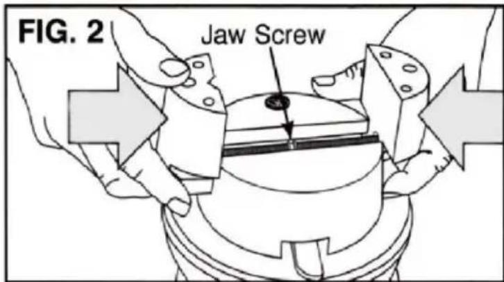

INSTRUCTION
natural_image
Technical line drawing of a mechanical component with a lever and base (no text or symbols)natural_image
Technical line drawing of a mechanical assembly with a tool and circular components (no text or symbols)8 petites épingles
natural_image
Technical line drawing of a mechanical component with a handle and base (no text or symbols)Plaques à broches
natural_image
Technical line drawing of a mechanical assembly with a tool and circular components (no text or symbols)Petites assiettes
natural_image
Technical line drawing of a mechanical device with a tool and circular components (no text or symbols)natural_image
Technical line drawing of a mechanical component with a handle and circular housing (no text or symbols)VEVOR®
TOUGH TOOLS, HALF PRICE
www.vevor.com/support
VEVOR®
TOUGH TOOLS, HALF PRICE
We continue to be committed to provide you tools with competitive price. "Save Half", "Half Price" or any other similar expressions used by us only represent of savings you might benefit from buying certain tools with us compared to top brands and does not necessarily mean to cover all categories of tools offered are kindly reminded to verify carefully when you are placing an order with us actually saving half in comparison with the top major brands.
VEVOR®
TOUGH TOOLS, HALF PRICE
MULTI-DIRECTIONAL MICROSCOPE
MODELL: JH-1A /JH-1B

natural_image
Mechanical robotic arm with articulated joints and mounting base (no visible text or symbols)NEED HELP? CONTACT US!
Have product questions? Need technical support? Please feel fr contact us:
Technical Support and E-Warranty Certificate www.vevor.com/support
This is the original instruction, please read all manual instruction carefully before operating. VEVOR reserves a clear interpretation user manual. The appearance of the product shall be subject to product you received. Please forgive us that we won't inform you there are any technology or software updates on our product.
Fig. 4
natural_image
Diagram of a microscope with two lenses and directional arrows indicating rotation (no text or labels)Fig.5
CLEAN AND CARE RULES
natural_image
Technical line drawings of a mechanical component, showing cross-sectional and top views (no text or symbols)


INSTRUCTION
natural_image
Technical line drawing of a mechanical component with a lever and base plate (no text or symbols)natural_image
Technical line drawing of a mechanical assembly with a tool and component (no text or symbols)natural_image
Technical line drawing of a mechanical component with a lever and base (no text or symbols)Pin-Platten
natural_image
Technical line drawing of a mechanical assembly with a tool and cylindrical components (no text or symbols)Kleine Teller
natural_image
Technical line drawing of a mechanical device with a lever and cylindrical components (no text or symbols)Runde Radiusstifte
natural_image
Technical line drawing of a mechanical component with a lever and base (no text or symbols)VEVOR®
TOUGH TOOLS, HALF PRICE
www.vevor.com/support
VEVOR®
TOUGH TOOLS, HALF PRICE
We continue to be committed to provide you tools with competitive price. "Save Half", "Half Price" or any other similar expressions used by us only represent of savings you might benefit from buying certain tools with us compared top brands and does not necessarily mean to cover all categories of tools offered are kindly reminded to verify carefully when you are placing an order with us actually saving half in comparison with the top major brands.
VEVOR®
TOUGH TOOLS, HALF PRICE
MULTI-DIRECTIONAL MICROSCOPE
MODEL: JH-1A /JH-1B

natural_image
Mechanical robotic arm with articulated joints and mounting base (no visible text or symbols)NEED HELP? CONTACT US!
Have product questions? Need technical support? Please feel fr contact us:
Technical Support and E-Warranty Certificate www.vevor.com/support
This is the original instruction, please read all manual instructions carefully before operating. VEVOR reserves a clear interpretation of user manual. The appearance of the product shall be subject to product you received. Please forgive us that we won't inform your data on your product.
Fig. 4
natural_image
Diagram of a microscope with two lenses and directional arrows indicating rotation (no text or labels)Fig.5
CLEAN AND CARE RULES
natural_image
Technical line drawing of a mechanical component with internal cavities and mounting base (no text or symbols)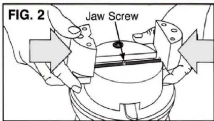

INSTRUCTION
natural_image
Technical line drawing of a mechanical component with a lever and base (no text or symbols)natural_image
Line drawing of a mechanical component with a tool and circular base (no text or symbols)8 małych szpilek
natural_image
Technical line drawing of a mechanical component with a lever and base (no text or symbols)Płytki pinowe
natural_image
Technical line drawing of a mechanical device with a handle and internal components (no text or symbols)Małe talerze
natural_image
Technical line drawing of a mechanical device with a lever and cylindrical components (no text or symbols)natural_image
Technical line drawing of a mechanical component with a handle and central hub (no text or symbols)VEVOR®
TOUGH TOOLS, HALF PRICE
www.vevor.com/support
VEVOR®
TOUGH TOOLS, HALF PRICE
We continue to be committed to provide you tools with competitive price. "Save Half", "Half Price" or any other similar expressions used by us only represent of savings you might benefit from buying certain tools with us compared to top brands and does not necessarily mean to cover all categories of tools offered are kindly reminded to verify carefully when you are placing an order with us actually saving half in comparison with the top major brands.
VEVOR®
TOUGH TOOLS, HALF PRICE
MULTI-DIRECTIONAL MICROSCOPE
MODELLO: JH-1A /JH-1B

natural_image
Black and white mechanical arm with articulated joints and a metallic stand (no visible text or symbols)NEED HELP? CONTACT US!
Have product questions? Need technical support? Please feel fr contact us:
Technical Support and E-Warranty Certificate www.vevor.com/support
This is the original instruction, please read all manual instructions carefully before operating. VEVOR reserves a clear interpretation of user manual. The appearance of the product shall be subject to product you received. Please forgive us that we won't inform your use, there are any technology or software updates on our product.
Fig. 4
natural_image
Diagram of a microscope with two lenses and directional arrows indicating rotation (no text or labels)Fig.5
CLEAN AND CARE RULES
natural_image
Technical line drawing of a mechanical component with internal cavities and mounting base (no text or symbols)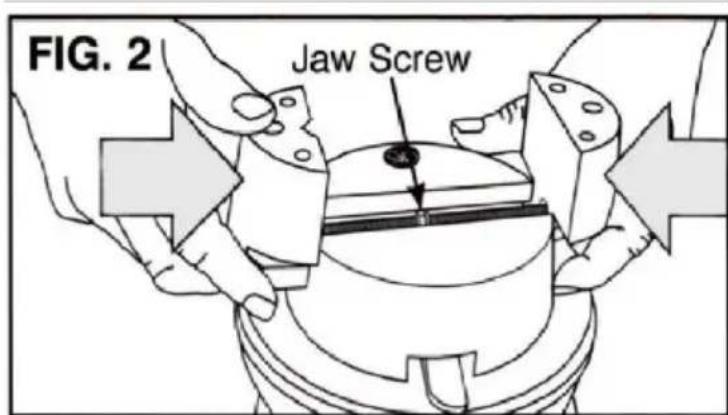


INSTRUCTION
natural_image
Technical line drawing of a mechanical component with a handle and mounting base (no text or symbols)natural_image
Line drawing of a mechanical component with a tool and circular base (no text or symbols)8 piccoli perni
natural_image
Technical line drawing of a mechanical component with a lever and base (no text or symbols)Piastre a perno
natural_image
Technical line drawing of a mechanical device with a handle and internal components (no text or symbols)Piccoli Piatti
natural_image
Technical line drawing of a mechanical device with a tool and circular components (no text or symbols)natural_image
Technical line drawing of a mechanical component with a handle and circular base (no text or symbols)VEVOR®
TOUGH TOOLS, HALF PRICE
www.vevor.com/support
VEVOR®
TOUGH TOOLS, HALF PRICE
We continue to be committed to provide you tools with competitive price. "Save Half", "Half Price" or any other similar expressions used by us only represent of savings you might benefit from buying certain tools with us compared to top brands and does not necessarily mean to cover all categories of tools offered are kindly reminded to verify carefully when you are placing an order with us actually saving half in comparison with the top major brands.
VEVOR®
TOUGH TOOLS, HALF PRICE
MULTI-DIRECTIONAL MICROSCOPE
MODELO: JH-1A /JH-1B
natural_image
Black and white mechanical arm with adjustable arms and a metallic stand (no visible text or symbols)NEED HELP? CONTACT US!
Have product questions? Need technical support? Please feel from contact us:
Technical Support and E-Warranty Certificate www.vevor.com/support
This is the original instruction, please read all manual instructions carefully before operating. VEVOR reserves a clear interpretation of user manual. The appearance of the product shall be subject to product you received. Please forgive us that we won't inform your data on your product.
Fig. 4
natural_image
Diagram of a microscope with two lenses and directional arrows indicating rotation (no text or labels)Fig.5
CLEAN AND CARE RULES
natural_image
Technical line drawing of a mechanical component with internal cavities and mounting base (no text or symbols)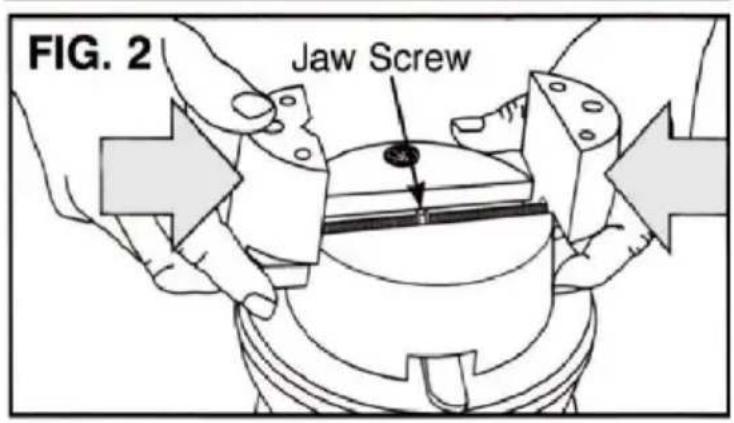

INSTRUCTION
natural_image
Technical line drawing of a mechanical component with a lever and base (no text or symbols)natural_image
Technical line drawing of a mechanical assembly with a tool and circular component (no text or symbols)natural_image
Technical line drawing of a mechanical component with a lever and base (no text or symbols)Placas de pasador
natural_image
Technical line drawing of a mechanical component with a handle and cylindrical parts (no text or symbols)Platos pequeños
natural_image
Technical line drawing of a mechanical device with a tool and cylindrical components (no text or symbols)natural_image
Technical line drawing of a mechanical component with a handle and circular base (no text or symbols)VEVOR®
TOUGH TOOLS, HALF PRICE
www.vevor.com/support
VEVOR®
TOUGH TOOLS, HALF PRICE
We continue to be committed to provide you tools with competitive price. "Save Half", "Half Price" or any other similar expressions used by us only represent of savings you might benefit from buying certain tools with us compared to top brands and does not necessarily mean to cover all categories of tools offered are kindly reminded to verify carefully when you are placing an order with us actually saving half in comparison with the top major brands.
VEVOR®
TOUGH TOOLS, HALF PRICE
MULTI-DIRECTIONAL MICROSCOPE
MODELL: JH-1A /JH-1B

natural_image
Mechanical robotic arm with articulated joints and a mounted base (no visible text or symbols)NEED HELP? CONTACT US!
Have product questions? Need technical support? Please feel fr contact us:
Technical Support and E-Warranty Certificate www.vevor.com/support
This is the original instruction, please read all manual instruction carefully before operating. VEVOR reserves a clear interpretation user manual. The appearance of the product shall be subject to product you received. Please forgive us that we won't inform you there are any technology or software updates on our product.
Fig. 4
natural_image
Diagram of a microscope with two lenses and directional arrows indicating rotation (no text or labels)Fig.5
CLEAN AND CARE RULES
natural_image
Technical line drawings of a mechanical component, showing cross-sectional and top views (no text or symbols)

INSTRUCTION
natural_image
Technical line drawing of a mechanical component with a lever and base (no text or symbols)natural_image
Technical line drawing of a mechanical assembly with a tool and circular component (no text or symbols)8 små stift
natural_image
Technical line drawing of a mechanical component with a lever and base (no text or symbols)Pin Plattor
natural_image
Technical line drawing of a mechanical assembly with a tool and circular components (no text or symbols)Små tallrikar
natural_image
Technical line drawing of a mechanical device with a tool and circular components (no text or symbols)Runda radie stift
natural_image
Technical line drawing of a mechanical component with a handle and circular base (no text or symbols)VEVOR®
TOUGH TOOLS, HALF PRICE
www.vevor.com/support