
HV-4-KP - Rotating table Vevor - Free user manual and instructions
Find the device manual for free HV-4-KP Vevor in PDF.

| Product type | Precision rotary table |
| Brand | Vevor |
| Model | HV-4-KP |
| Usage | Horizontal and vertical |
| Reduction ratio | 1:90 |
| Rotation per crank turn | 4° |
| Micrometer collar graduation | 1 minute (1') |
| Vernier reading | 10 seconds (10'') |
| Rapid division | From 2 to 100 with dividing plate |
| Body material | Cast iron |
| Power supply | Manual |
| Main functions | Precision machining, dividing, drilling, milling |
| Maintenance and cleaning | Clean regularly, lubricate the worm gear with light oil |
| Safety | Read the manual before use, wear protective equipment |
| Spare parts and repairability | Parts available on request, specify model and part number |
| General information | Warranty and technical support via www.vevor.com/support |
| Included accessories | Main body, handle, chuck key, reverse jaws (3 pieces), T-bolts M10x40 (2), M10 nuts (2), instructions |
Frequently Asked Questions - HV-4-KP Vevor
User questions about HV-4-KP Vevor
0 question about this device. Answer the ones you know or ask your own.
Ask a new question about this device
Download the instructions for your Rotating table in PDF format for free! Find your manual HV-4-KP - Vevor and take your electronic device back in hand. On this page are published all the documents necessary for the use of your device. HV-4-KP by Vevor.
USER MANUAL HV-4-KP Vevor
Technical Support and E-Warranty Certificate www.vevor.com/support
ROTARY TABLE
MODEL: HV-4-KP, HV-4-4, HV-4-4R, HV-6-4, HV-6-4B, HV-8-4, HV-8-3
We continue to be committed to provide you tools with competitive price. "Save Half", "Half Price" or any other similar expressions used by us only represent of savings you might benefit from buying certain tools with us compared major top brands and does not necessarily mean to cover all categories of tools us. You are kindly reminded to verify carefully when you are placing an order we are actually saving half in comparison with the top major brands.
MODEL: HV-4-KP, HV-4-4, HV-4-4R, HV-6-4, HV-6-4B, HV-8-4 HV-8-3

NEED HELP? CONTACT US!
Have product questions? Need technical support? Please feel free contact us:
Technical Support and E-Warranty Certificate www.vevor.com/support
This is the original instruction, please read all manual instruction carefully before operating. VEVOR reserves a clear interpretation user manual. The appearance of the product shall be subject to product you received. Please forgive us that we won't inform you there are any technology or software updates on our product.

Warning-To reduce the risk of injury, user must read instructions manual carefully.
natural_image
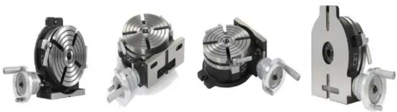
Four different types of industrial cutting machines shown from front, side, top, and back views (no text or labels visible)PRECISION ROTARY TABLES
Two types of Rotary tables are summarized here collectively. The mechanisms common to these tables are shown on some pages of their description.
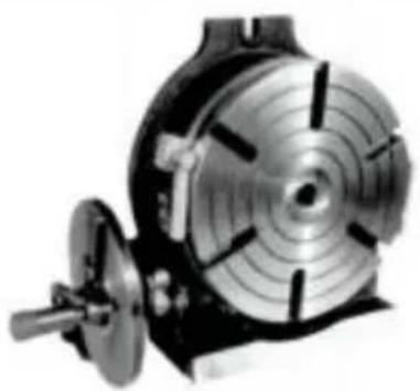
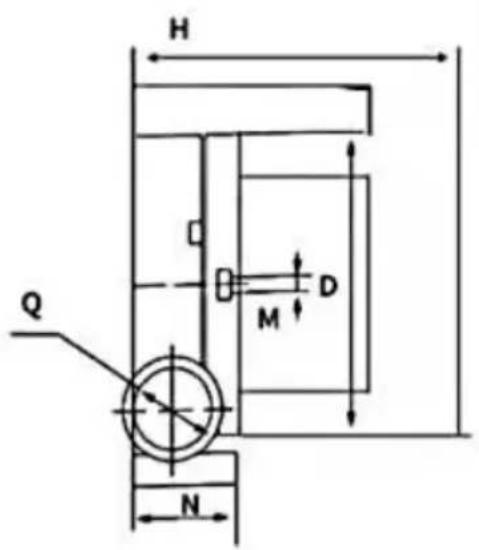
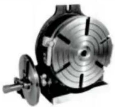
HORIZONTAL/VERTICAL PRECISION ROTARY TABLE
This rotary table is designed to permit machining operations at a high dimension than that of Horizontal Type rotary tables. The base can used in a vertical position to enable it to carry out center work.

| Horizontal/Vertical Type | Model No. | Duter diameter | Height | Height | Worm Gear ratio | Center sileeve | Width of slots | Bolt slots |
 | D(inch/mm) | H(inch/mm) | C(inch/mm) | / | / | M(inch/mm) | G (inch/mm) | |
| HV-4-4R | 4*101.6mm | 2.76*70mm | 3.35*85mm | 1:36 | / | 0.31*8mm | / | |
| HV-4-KP | 4*101.6mm | 4.72"120mm | 3.35"85mm | 1:36 | / | / | / | |
| HV-4-4 | 4*101.6mm | 3.35*85mm | 3.35*85mm | 1:72 | MT2 | 0.47*12mm | 0.55*14mm | |
| HV-6-4B | 6*152.4mm | 3.35*85mm | 3.94*100mm | 1:90 | MT2 | 0.55*14mm | 0.63*16mm | |
| HV-6-4 | 6*152.4mm | 3.35*85mm | 3.94*100mm | 1:90 | MT2 | 0.55*14mm | 0.63*16mm | |
| HV-8-4 | 8*203.2mm | 4.13*105mm | 5.31*135mm | 1:90 | MT3 | 0.55*14mm | 0.63*16mm | |
| HV-8-3 | 8*203.2mm | 4.13*105mm | 5.31*135mm | 1:90 | MT3 | 0.55*14mm | 0.63*16mm |
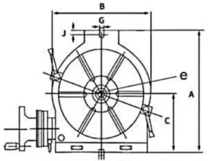
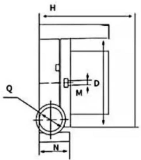
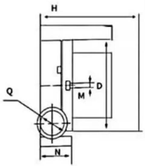
| Model | HV-3" | HV-4" | HV-5" |
| A | 98 | 145 | 155 |
| B | 78 | 114 | 127 |
| C | 59 | 85.5 | 90 |
| D | F76.2 | F110 | F127 |
| E | 12 | 12 | 12 |
| G | |||
| H | 83 | 85 | 85 |
| J | 15 | ||
| M | MT2 | MT2 | |
| N | 71 | 68 | 68 |
-
Adjusting Mesh of Worm Gear: Loosen the metal clamp handle and turn the switch metal clockwise until it touches the stopper. The worm gear has now been disengaged. Turn it counterclockwise until it touches the stopper, the worm and gear wheel will engage. Tighten the metal clamp handle after engagement. An additional adjustment can be obtained by removing the screw ④ and steel ball and turning the inner screw ⑥ counterclockwise, so bringing the worm in closer engagement with the gear wheel. Turning clockwise brings the worm away from the wheel. After adjustment insert the steel ball and tighten screw ④
-
Axial Adjustment of Worm Shaft: When axial slack occurs gear adjustment is carried out by tightening the inside worm shaft nut after handle, vernier ring and switch metal have been removed. After adjusting lock the nut on the shaft by means of the set screw. (The ERT-6 h adjusting nut, which can be used after removal of the handle.)
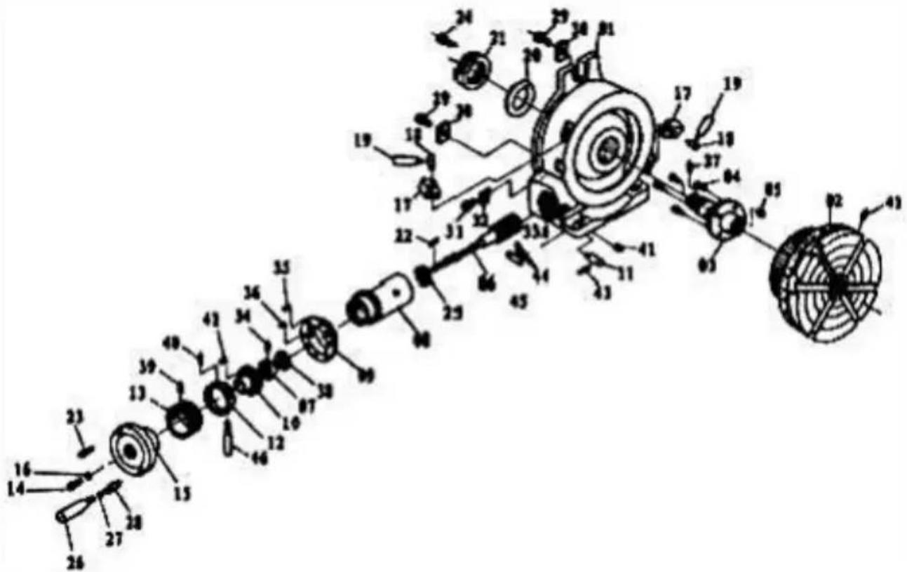
PARTS LIST For HV6,HV8,HV10,HV12,HV14,HV16
| Part No. | Description | Part No. | Description |
| HV-P01 | Main body | HV-P24 | Hex.socket cap screw |
| HV-P02 | Table | HV-P25 | Bearing thrust collar |
| HV-P03 | Table sleeve | HV-P26 | Handle |
| HV-P04 | Hex.socket cap screw | HV-P27 | Circlips |
| HV-P05 | Oil cup | HV-P28 | Screw rod |
| HV-P06 | Worm rod | HV-P29 | Hex.socket cap screw |
| HV-p07 | Lock nuts | HV-P30 | Guide key |
| HV-P08 | Worm metal | HV-P31 | Hex.socket cap screw |
| HV-P09 | Adjusting dial | HV-P32 | Limit Plate |
| HV-P10 | Adjusting dial | HV-P33 | Set screw |
| HV-P11 | Metal setting screw | HV-P34 | Set screw |
| HV-P12 | Vernier ring | HV-P35 | Hex.socket cap screw |
| HV-P13 | Micro-collar | HV-P36 | Set screw |
| HV-P14 | Hex.Socket cap screw | HV-P37 | Pin |
| HV-P15 | Handle wheel | HV-P38 | Bearing thrust collar |
| HV-P16 | Washer | HV-P39 | Collar set screw |
| HV-P17 | Clamp piece | HV-P40 | Collar set screw |
| HV-P18 | Clamp bolt | HV-P41 | Oil cup |
| HV-P19 | Clamp handle | HV-P42 | Hex.socket cap screw |
| HV-P20 | Ring | HV-P43 | Lock handle |
| HV-P21 | Lock nuts | HV-P44 | Rivets |
| HV-P22 | Key | HV-P45 | Plate |
| HV-P23 | Handle | HV-P46 | Handle |
Operating Instruction and Function of Each Unit
- The worm gear ratio is 1:90.
• one tum of the handle moves the table by 4^
- Micro-collar is graduated in steps of 1 min.
- Vernier scale makes settings down to 10 seconds possible. (20 seconds for (HV6)
-
Dividing of 2 to 100 can be carried out quickly and accurately by attaching a Dividing Mechanism.
-
Center work can also be carried out by using the base in the vertical position in conjunction with a tailstock.(See Page 4.)
\* Suggestions for Order
When ordering parts for replacement, indicate Model No. and Part No.
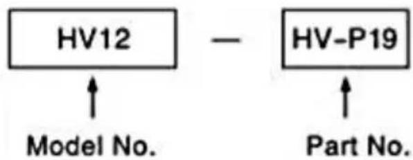
flowchart
graph TD
    A["HV12"] --> B["Model No."]
    C["HV-P19"] --> D["Part No."]
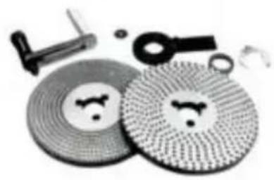
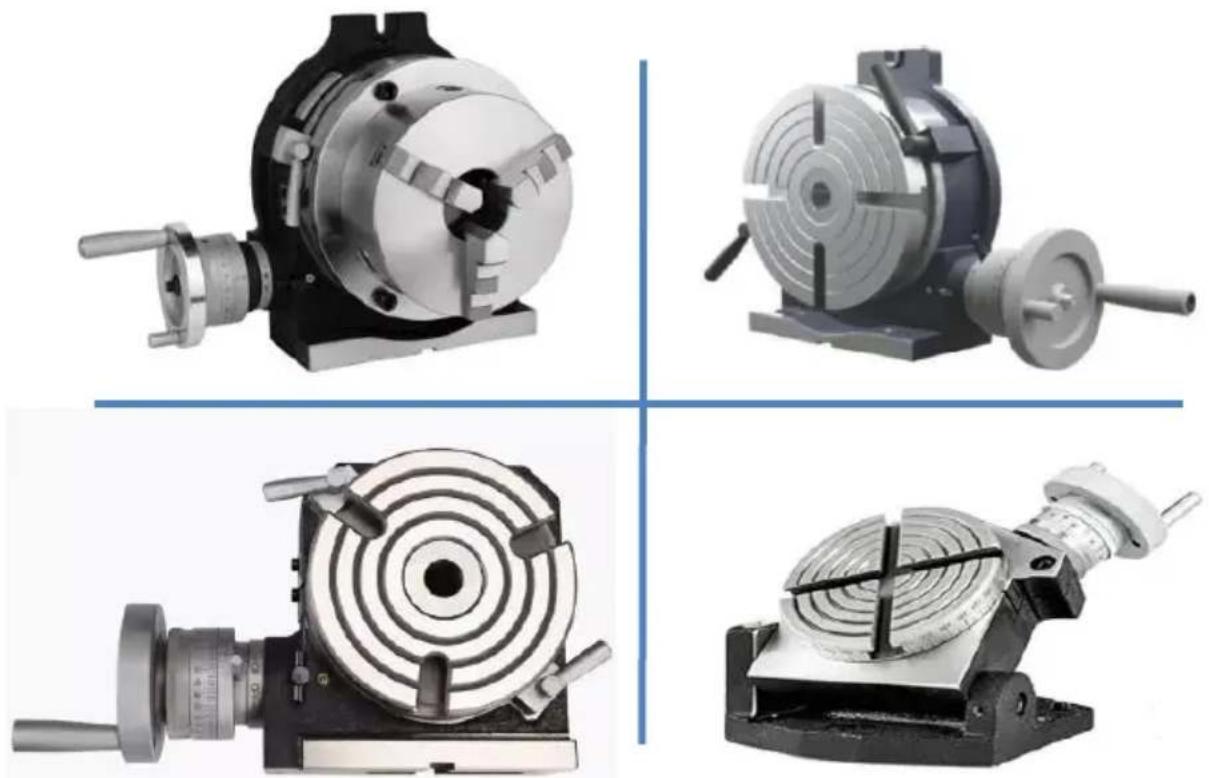
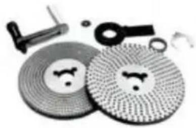
OPTIONAL ACCESSORIESDIVIDING PLATES
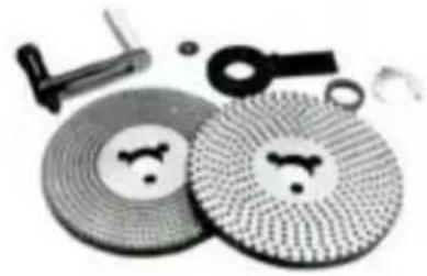
Dividing Mechanism
natural_image
Assorted mechanical components including a hammer, tools, and circular components with textured surfaces (no visible text or symbols)Dividing Plate set includes index plate, crank handle, 3 pcs screw, sector, & U-washer

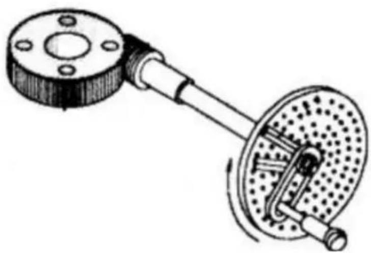
natural_image
Mechanical device with circular components and a shaft (no visible text or symbols)
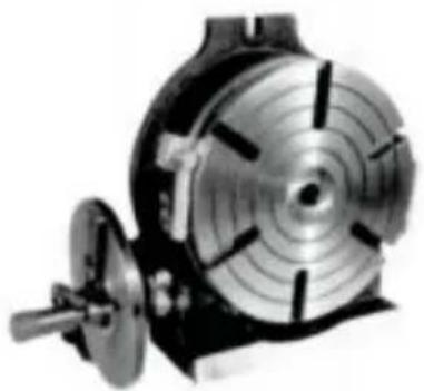
RT with Dividing Plate
SPECIFICATIONS FOR DIVIDING PLATES Unit:mm/inches
| MODEL NO | Major dimension of DM | Weight kg/lb | Applicable table | ||||
| Dividing Plate screw | Inner diameter of sector am | Outer diameter of spring clip | Grove width in handle plate | ||||
| DP-1 | PCD.(32/ 1.26)I | 210.83 | 180.71 | 90.03 | 255.51 | MINI (HV3HV4/HV5) HV6 | P7P9P10 |
| DP-2 | (3holes)PCD.46/1.81 | 28.71.12 | 441.73 | 100.39 | 48.82 | HV8,10, 12, 14 | P7P9P10 |
In case of An Optional DM Device Attached
Indexing of 2 to 100 can be made accurately and quickly.
Equation of Indexing
Since the worm ratio is 1:90, when the handle is made to rotate a 360^ revolution, the table therefore will rotate a 1/90 revolution. The relationships between handle revolution 'N' and individual number 'T' to be sought are shown in the following equation:
$$ N = \frac {9 0}{T} $$
Remarks: The index table on Page 6 is made on the basis of this e (Example)
In case where the operator wants to index the position divided into equal parts. Hints on operation As for 29 individual numbers, the num
$$ 3 \frac {9}{8 7} $$
of crank handle revolutions (N)is as shown in the table on Page 6,So that the handle should be rotated a full 360^ revolution three time plus an interval of nine holes (in this time,it means hole intervals no numbers).After setting this point as a start point,rotate the handle a f 360^ revolution three times plus an interval of nine holes (in this time, means hole intervals not hole numbers).After setting this point as a s point,rotate the handle a full 360^ revolution three times plus an interval nine holes.When the procedure is repeated in turn as many as 29 ti indexing of dividing into 29 equal parts is thus achieved.
natural_image
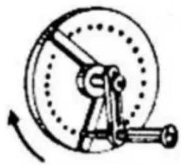
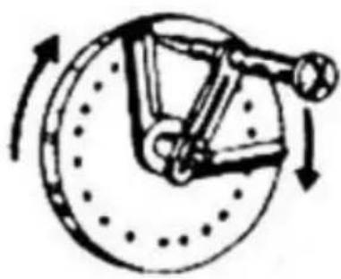
Mechanical diagram showing a flanged component connected to a rotating wheel assembly (no text or labels)Operations of Crank Handle and Sector
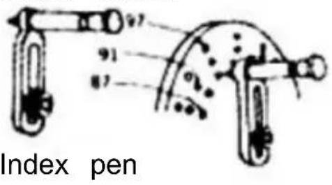
In case of the Example' Division into 29 Equal Parts' aforesaid, it is natural that indexing operation should proceed with the intervals of n holes after setting the index plate (B plate) on which a row of 87 h are provided. But in this method, the operator has to count nine holes' intervals one by one. He must feel inefficient. In this viewpoint, it is necessary to use a device called 'sector' to avoid such troublesome procedures. The following will describe some necessary procedures for operation of the sector.
a. Loosen the crank handle lock nut, adjust its length so as to cause the index pin in the train of 87 holes, and tighten it.
b. Loosen the set-screws of the sector.ope two arms in accordance with the interval nine holes (total numbers of holes is ten) and tighten with setscrews.
c. First, bring the left arm of the sector net to the index pin's left side.
d. Next, rotate the crank handle clockwise apply it to the right arm of the sector so the index pin will fall in the hole located this right arm's left side surface.
e. Rotate the sector clockwise this time, an put the right side surface of the left arm the left side of the index pin. In this time, relationships between the index pin and the sector's left arm in their positions are the same as in Par.c).
The index plate hole that actually accommodates the index pin is located at the point where it goes across ten holes the right away from the hole as in par.c) f. Repeat the same procedures as necessary.
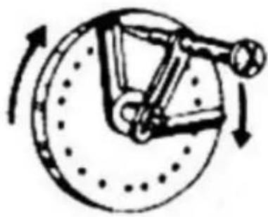
Crank handle
natural_image
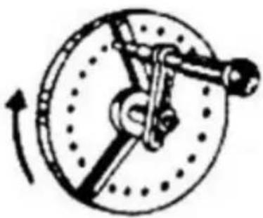
Mechanical diagram of a wheel and linkage mechanism with rotational arrow (no text or labels)Fig 5
Fig 6

natural_image
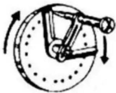
Mechanical diagram showing a rotating disk with a lever and rotational arrow (no text or labels)Fig 7

natural_image
Diagram of a mechanical device with rotating components and directional arrows indicating motion (no text or symbols)Fig 8
Index Table(For worm ratio 1:90) DP-1 For HV6/MINI(HV3/HV4/HV5)
| T | H | N | T | H | N | T | H | N |
| 1 | 43 | 2 4/43 | 82 | C-41 | 1 4/11 | |||
| 2 | 45 | 44 | C-43 | 83 | ||||
| 3 | 30 | 45 | 2 | 84 | ||||
| 4 | A-20 | 22 10/20 | 46 | B-23 | 1 22/23 | 85 | ||
| 5 | 18 | 47 | C-47 | 1 43/47 | 86 | C-43 | 1 2/43 | |
| 6 | 15 | 48 | A-16 | 1 14/16 | 87 | B-29 | 1 1/29 | |
| 7 | B-21 | 12 8/21 | 49 | C-49 | 1 41/49 | 88 | ||
| 8 | A-20 | 11 5/20 | 50 | A-20 | 1 16/20 | 89 | ||
| 9 | 10 | 51 | 90 | |||||
| 10 | 9 | 52 | 91 | |||||
| 11 | B-33 | 8 6/33 | 53 | 92 | ||||
| 12 | A-20 | 7 10/20 | 54 | A-18 | 1 12/18 | 93 | B-31 | 30/31 |
| 13 | C-39 | 6 30/39 | 55 | B-33 | 1 21/33 | 94 | C-47 | 45/47 |
| 14 | B-21 | 6 9/21 | 56 | 95 | A-19 | 18/19 | ||
| 15 | 6 | 57 | A-19 | 1 11/19 | 96 | A-16 | 15/16 | |
| 16 | A-16 | 5 10/16 | 58 | B-29 | 1 16/29 | 97 | ||
| 17 | A-17 | 5 5/17 | 59 | 98 | C-49 | 45/49 | ||
| 18 | 5 | 60 | A-20 | 1 1/20 | 99 | B-33 | 30/33 | |
| 19 | A-19 | 4 14/19 | 61 | 100 | A-20 | 18/20 | ||
| 20 | A-20 | 4 10/20 | 62 | B-31 | 1 14/31 | |||
| 21 | B-21 | 4 6/21 | 63 | B-21 | 1 9/21 | |||
| 22 | B-33 | 4 3/33 | 64 | |||||
| 23 | B-23 | 3 21/23 | 65 | C-39 | 1 15/39 | |||
| 24 | A-20 | 3 15/20 | 66 | B-33 | 1 12/33 | |||
| 25 | A-20 | 3 12/20 | 67 | |||||
| 26 | C-39 | 3 18/39 | 68 | |||||
| 27 | A-18 | 3 6/18 | 69 | B-23 | 1 7/23 | |||
| 28 | 70 | B-21 | 1 6/21 | |||||
| 29 | B-29 | 3 3/29 | 71 | |||||
| 30 | 3 | 72 | A-20 | 1 5/20 | ||||
| 31 | B-31 | 2 28/31 | 73 | |||||
| 32 | A-16 | 2 13/16 | 74 | C-37 | 1 8/37 | |||
| 33 | B-33 | 2 24/33 | 75 | A-20 | 1 4/20 | |||
| 34 | A-17 | 2 11/17 | 76 | |||||
| 35 | B-21 | 2 12/21 | 77 | |||||
| 36 | A-20 | 2 10/20 | 78 | C-39 | 1 6/39 | |||
| 37 | C-37 | 2 16/37 | 79 | |||||
| 38 | A-19 | 2 7/19 | 80 | A-16 | 1 2/16 | |||
| 39 | C-39 | 2 12/39 | 81 | A-18 | 1 2/18 | |||
| 40 | A-20 | 2 15/20 | ||||||
| 41 | C-41 | 2 8/41 | ||||||
| 42 | B-21 | 2 3/21 |
DP-2 For HV8,HV10,HV12,HV14,HV16
| T | H | N | T | H | N | T | H | N |
| 2 | 45 | 32 | A-32 | 2 26/32 | 65 | B-91 | 1 35/91 | |
| 3 | 30 | 33 | B-99 | 2 72/99 | 66 | A-44 | 1 16/44 | |
| 4 | A-26 | 22 13/26 | 34 | A-34 | 2 22/34 | B-99 | 1 36/99 | |
| A-28 | 22 14/28 | 35 | A-28 | 2 16/28 | 67 | B-67 | 1 23/67 | |
| 5 | 18 | B-63 | 2 36/63 | 68 | A-34 | 1 11/34 | ||
| 6 | 15 | 36 | A-26 | 2 13/26 | 69 | A-46 | 1 14/46 | |
| 7 | A-28 | 12 24/28 | A-28 | 2 14/28 | B-69 | 1 21/69 | ||
| A-77 | 12 66/77 | 37 | A-37 | 2 16/37 | 70 | A-28 | 1 8/28 | |
| 8 | A-28 | 11 7/28 | 38 | A-38 | 2 14/38 | B-63 | 1 18/63 | |
| A-44 | 11 11/44 | 39 | A-26 | 2 8/26 | 71 | B-71 | 1 19/71 | |
| 9 | 10 | B-91 | 2 28/91 | 72 | A-32 | 1 8/32 | ||
| 10 | 9 | 40 | A-28 | 2 7/28 | A-44 | 1 11/44 | ||
| 11 | A-44 | 8 8/44 | A-44 | 2 11/44 | 73 | B-73 | 1 17/73 | |
| B-77 | 8 14/77 | 41 | A-41 | 2 8/41 | 74 | A-37 | 1 8/37 | |
| 12 | A-26 | 7 13/26 | 42 | A-28 | 2 4/28 | 75 | A-30 | 1 6/30 |
| A-28 | 7 14/28 | B-63 | 2 9/63 | 76 | A-38 | 1 7/38 | ||
| 13 | A-29 | 6 24/26 | 43 | A-43 | 2 4/43 | 77 | B-77 | 1 13/77 |
| B-91 | 6 84/91 | 44 | A-44 | 2 2/44 | 78 | A-39 | 1 6/39 | |
| 14 | A-28 | 6 12/28 | 45 | 2 | B-91 | 1 14/91 | ||
| B-77 | 6 33/77 | 46 | A-46 | 1 44/46 | 79 | B-79 | 1 11/79 | |
| 15 | 6 | B-69 | 1 66/69 | 80 | A-32 | 1 4/32 | ||
| 16 | A-32 | 5 20/32 | 47 | A-47 | 1 43/47 | 81 | B-63 | 1 7/63 |
| 17 | A-34 | 5 10/34 | 48 | A-32 | 1 28/32 | 81 | B-81 | 1 9/81 |
| 18 | 5 | 49 | A-49 | 1 41/49 | 82 | A-41 | 1 4/41 | |
| 19 | A-38 | 4 28/38 | 50 | A-30 | 1 24/30 | 83 | B-83 | 1 7/83 |
| 20 | A-26 | 4 13/26 | 51 | A-34 | 1 26/34 | 84 | A-28 | 1 2/28 |
| A-28 | 4 14/28 | 52 | A-26 | 1 19/26 | 85 | A-34 | 1 2/34 | |
| 21 | A-28 | 4 8/28 | 53 | A-53 | 1 37/53 | 86 | A-43 | 1 2/43 |
| B-77 | 4 22/77 | 54 | A-30 | 1 20/30 | 87 | B-87 | 1 3/87 | |
| 22 | A-44 | 4 4/44 | B-63 | 1 42/63 | 88 | A-44 | 1 1/44 | |
| B-77 | 4 7/77 | 55 | A-44 | 1 28/44 | 89 | B-89 | 1 1/89 | |
| 23 | A-46 | 3 42/46 | B-77 | 1 49/77 | 90 | 1 | ||
| B-69 | 3 63/69 | 56 | A-28 | 1 17/28 | 91 | B-91 | 90/91 | |
| 24 | A-28 | 3 21/28 | 57 | B-38 | 1 22/38 | 92 | A-46 | 45/46 |
| B-44 | 3 33/44 | 58 | B-87 | 1 48/87 | 93 | B-93 | 90/93 | |
| 25 | A-30 | 3 18/30 | 59 | A-59 | 1 31/59 | 94 | A-47 | 45/47 |
| 26 | A-26 | 3 12/26 | 60 | A-34 | 1 17/34 | 95 | A-38 | 36/38 |
| B-91 | 3 42/91 | A-32 | 1 16/32 | 96 | A-32 | 30/32 | ||
| 27 | A-30 | 3 10/30 | 61 | B-61 | 1 29/61 | 97 | B-97 | 90/97 |
| B-63 | 3 21/63 | 62 | B-93 | 1 42/93 | 98 | A-49 | 45/49 | |
| 28 | A-28 | 3 6/28 | 63 | B-49 | 1 21/49 | 99 | A-44 | 40/44 |
| 29 | B-87 | 3 9/87 | B-77 | 1 33/77 | B-99 | 90/99 | ||
| 30 | 3 | 64 | A-32 | 1 13/32 | 100 | A-30 | 27/30 | |
| 31 | B-93 | 2 84/93 | 65 | A-26 | 1 10/26 |
Description of in the index table.
This table is the one being calculated for the index plate with hole numbers shown below.
Description of codes used in the index table
T: Desired individual number
N: Number of revolutions of the index plate :Option
A: Using A plate
B: Using B plate
Number of holes
DP-1
A Plate 15, 16,17, 18,19,20
B Plate 21,23,27,29,31,33
C Plate 37,39,41,43,47,49
DP-2
A Plate 26,28,30,32,34,37,38,39,41,43,44,46,47,49,51,53,57,59
B Plate 61,63,67,69,71,73,77,79,81,83,87,89,91,93,97,99
PARTS LIST
Model: HV-4-KP
- Main body * 1
- Handle * 2
- Chuck wrench * 1
- Reverse jaws * 1 set (3pcs)
- M10 * 40 T-bolt * 2
- M10 nut * 2
- Instructions * 1
Model: HV-4-4
- Main body * 1
- Handle * 2
- M6 * 55 bolt * 2
- M6 nut * 2
- φ 6 flat gasket * 2
- Positioning block * 2
- Pressing plate * 2
- Cushion block * 2
-
Instructions * 1
-
A partition board * 1
- B partition board * 1
-
C partition board * 1
-
Rocker handle * 1
-
M8 * 70 hex socket handle screw * 1
-
Division plate positioning regulator * 1
-
Limit block * 1
-
Circlip * 1
-
M5 * 10 Phillips screw * 3
Model: HV-4-4R
- Main body * 1
- Handle * 2
- M6 * 55 bolt * 2
- M6 nut * 2
- φ 6 flat gasket * 2
- Positioning block * 2
- Pressing plate * 2
- Cushion block * 2
- Instructions * 1
Model: HV-6-4B
- A partition board * 1
- B partition board * 1
- C partition board * 1
- Rocker handle * 1
- M8 * 70 hex socket handle screw * 1
- Division plate positioning regulator * 1
- Limit block * 1
- Circlip * 1
- M5 * 10 Phillips screw * 3
- M5 * 10 hex socket screw * 4
- Positioning block * 4
- M12 * 40 T-bolt * 2
- Nut * 2
- Internal hexagonal wrench * 1
- Instructions * 1
Model: HV-6-4
- Main body * 1
- Rocker handle * 1
- M8 * 70 hex socket handle screw * 1
- M5 * 10 hex socket screw * 4
- Positioning block * 4
- M12 * 40 T-bolt * 2,
- Nut * 2
- Instructions * 1
Model: HV-8-4
- Main body * 1
- Handle * 2
- Nut * 2
- M10 * 80 hexagonal handle bolt * 1
- Positioning block * 4
- M5 * 8 hexagonal socket bolt * 4
- M14 * 60 T-bolt * 2
- Internal hexagonal wrench * 1
- Instructions * 1
Model: HV-8-3
- Main body * 1
- Handle * 2
- M10 * 80 hex socket handle screw * 1
- Positioning block * 4
- M5 * 8 hexagonal socket bolt * 4
- M14 * 60 T-bolt * 2
- Internal hexagonal wrench * 1
- Nut * 2
- Instructions * 1
Address: Baoshanqu Shuangchenglu 803long 11hao 1602A-1609shi Shanghai
Imported to AUS: SIHAO PTY LTD. 1 ROKEVA STREETEASTWOOD NSW 2122 Australia
Imported to USA: Sanven Technology Ltd. Suite 250. 9166 Anaheim Place, Rancho Cucamonga, CA 91730
| EC | REP |
SHUNSHUN GmbH
Römeräcker 9 Z2021, 76351 Linkenheim-Hochstetten, Germany
| UK | REP |
Pooledas Group Ltd
Unit 5 Albert Edward House, The
Pavilions Preston, United Kingdom
Made In China
VEVOR®
TOUGH TOOLS, HALF PRICE
Technical Support and E-Warranty Certificate www.vevor.com/support
VEVOR®
TOUGH TOOLS, HALF PRICE
We continue to be committed to provide you tools with competitive price. "Save Half", "Half Price" or any other similar expressions used by us only represent of savings you might benefit from buying certain tools with us compared major top brands and does not necessarily mean to cover all categories of tools us. You are kindly reminded to verify carefully when you are placing an order where are actually saving half in comparison with the top major brands.
MODÈLE : HV-4-KP, HV-4-4, HV-4-4R, HV-6-4, HV-6-4B, HV-8-4 HV-8

BESOIN AIDE ? CONTACT NOUS !
natural_image
Four different types of industrial cutting machines shown from different angles (front, top, side, and front) with no visible text or symbols.PRECISION ROTARY TABLES
| Horizontal/Vertical Type | Model No. | Duter diameter | Height | Height | Worm Gear ratio | Center sileeve | Width of slots | Bolt slots |
| D(inch/mm) | H(inch/mm) | C(inch/mm) | / | / | M(inch/mm) | G (inch/mm) | ||
| HV-4-4R | 4*101.6mm | 2.76*70mm | 3.35*85mm | 1:36 | / | 0.31*8mm | / | |
| HV-4-KP | 4*101.6mm | 4.72"120mm | 3.35"85mm | 1:36 | / | / | / | |
| HV-4-4 | 4*101.6mm | 3.35*85mm | 3.35*85mm | 1:72 | MT2 | 0.47*12mm | 0.55*14mm | |
| HV-6-4B | 6*152.4mm | 3.35*85mm | 3.94*100mm | 1:90 | MT2 | 0.55*14mm | 0.63*16mm | |
| HV-6-4 | 6*152.4mm | 3.35*85mm | 3.94*100mm | 1:90 | MT2 | 0.55*14mm | 0.63*16mm | |
| HV-8-4 | 8*203.2mm | 4.13*105mm | 5.31*135mm | 1:90 | MT3 | 0.55*14mm | 0.63*16mm | |
| HV-8-3 | 8*203.2mm | 4.13*105mm | 5.31*135mm | 1:90 | MT3 | 0.55*14mm | 0.63*16mm |
| Modèle | HT - | HT - | HT - |
| UN | 98 | 145 | 155 |
| B | 78 | 114 | 127 |
| C | 59 | 8 5,5 | 90 |
| D | F7 6.2 | F110 | F 1 2 |
| E | 12 | 12 | 12 |
| g | |||
| H | 83 | 85 | 85 |
| J. | 15 | ||
| M. | MT2 | MT2 | |
| N | 71 | 68 | 68 |
PARTS LIST For HV6,HV8,HV10,HV12,HV14,HV16
| Part No. | Description | Part No. | Description |
| HV-P01 | Main body | HV-P24 | Hex.socket cap screw |
| HV-P02 | Table | HV-P25 | Bearing thrust collar |
| HV-P03 | Table sleeve | HV-P26 | Handle |
| HV-P04 | Hex.socket cap screw | HV-P27 | Circlips |
| HV-P05 | Oil cup | HV-P28 | Screw rod |
| HV-P06 | Worm rod | HV-P29 | Hex.socket cap screw |
| HV-p07 | Lock nuts | HV-P30 | Guide key |
| HV-P08 | Worm metal | HV-P31 | Hex.socket cap screw |
| HV-P09 | Adjusting dial | HV-P32 | Limit Plate |
| HV-P10 | Adjusting dial | HV-P33 | Set screw |
| HV-P11 | Metal setting screw | HV-P34 | Set screw |
| HV-P12 | Vernier ring | HV-P35 | Hex.socket cap screw |
| HV-P13 | Micro-collar | HV-P36 | Set screw |
| HV-P14 | Hex.Socket cap screw | HV-P37 | Pin |
| HV-P15 | Handle wheel | HV-P38 | Bearing thrust collar |
| HV-P16 | Washer | HV-P39 | Collar set screw |
| HV-P17 | Clamp piece | HV-P40 | Collar set screw |
| HV-P18 | Clamp bolt | HV-P41 | Oil cup |
| HV-P19 | Clamp handle | HV-P42 | Hex.socket cap screw |
| HV-P20 | Ring | HV-P43 | Lock handle |
| HV-P21 | Lock nuts | HV-P44 | Rivets |
| HV-P22 | Key | HV-P45 | Plate |
| HV-P23 | Handle | HV-P46 | Handle |
flowchart
graph TD
    A["HV12"] --> B["Model No."]
    C["HV-P19"] --> D["Part No."]
OPTIONAL ACCESSORIESDIVIDING PLATES
Dividing Mechanism

natural_image
Assorted mechanical components including a hammer, gear, and circular parts with textured surfaces (no visible text or symbols)Dividing Plate set includes index plate, crank handle, 3 pcs screw, sector, & U-washer

natural_image
Mechanical component with concentric circular grooves and a shaft (no visible text or symbols)
natural_image
Mechanical diagram showing a flanged component connected to a rotating shaft with a dotted circular base (no text or symbols)natural_image
Mechanical diagram of a wheel and linkage mechanism with rotational arrow (no text or labels)figure
figure

natural_image
Mechanical diagram showing a rotating disk with a lever and rotating shaft (no text or symbols)Fig

natural_image
Diagram of a mechanical device with rotating components and directional arrows indicating motion (no text or symbols)figue
Indice Tableau ( Pour ver rapport 1 : 90) DP-1 Pour HV6/MINI(HV3/HV4/HV5)
| T | H | N | T | H | N | T | H | N |
| 1 | 43 | 2 4/43 | 82 | C-41 | 1 4/11 | |||
| 2 | 45 | 44 | C-43 | 83 | ||||
| 3 | 30 | 45 | 2 | 84 | ||||
| 4 | A-20 | 22 10/20 | 46 | B-23 | 1 22/23 | 85 | ||
| 5 | 18 | 47 | C-47 | 1 43/47 | 86 | C-43 | 1 2/43 | |
| 6 | 15 | 48 | A-16 | 1 14/16 | 87 | B-29 | 1 1/29 | |
| 7 | B-21 | 12 8/21 | 49 | C-49 | 1 41/49 | 88 | ||
| 8 | A-20 | 11 5/20 | 50 | A-20 | 1 16/20 | 89 | ||
| 9 | 10 | 51 | 90 | |||||
| 10 | 9 | 52 | 91 | |||||
| 11 | B-33 | 8 6/33 | 53 | 92 | ||||
| 12 | A-20 | 7 10/20 | 54 | A-18 | 1 12/18 | 93 | B-31 | 30/31 |
| 13 | C-39 | 6 30/39 | 55 | B-33 | 1 21/33 | 94 | C-47 | 45/47 |
| 14 | B-21 | 6 9/21 | 56 | 95 | A-19 | 18/19 | ||
| 15 | 6 | 57 | A-19 | 1 11/19 | 96 | A-16 | 15/16 | |
| 16 | A-16 | 5 10/16 | 58 | B-29 | 1 16/29 | 97 | ||
| 17 | A-17 | 5 5/17 | 59 | 98 | C-49 | 45/49 | ||
| 18 | 5 | 60 | A-20 | 1 1/20 | 99 | B-33 | 30/33 | |
| 19 | A-19 | 4 14/19 | 61 | 100 | A-20 | 18/20 | ||
| 20 | A-20 | 4 10/20 | 62 | B-31 | 1 14/31 | |||
| 21 | B-21 | 4 6/21 | 63 | B-21 | 1 9/21 | |||
| 22 | B-33 | 4 3/33 | 64 | |||||
| 23 | B-23 | 3 21/23 | 65 | C-39 | 1 15/39 | |||
| 24 | A-20 | 3 15/20 | 66 | B-33 | 1 12/33 | |||
| 25 | A-20 | 3 12/20 | 67 | |||||
| 26 | C-39 | 3 18/39 | 68 | |||||
| 27 | A-18 | 3 6/18 | 69 | B-23 | 1 7/23 | |||
| 28 | 70 | B-21 | 1 6/21 | |||||
| 29 | B-29 | 3 3/29 | 71 | |||||
| 30 | 3 | 72 | A-20 | 1 5/20 | ||||
| 31 | B-31 | 2 28/31 | 73 | |||||
| 32 | A-16 | 2 13/16 | 74 | C-37 | 1 8/37 | |||
| 33 | B-33 | 2 24/33 | 75 | A-20 | 1 4/20 | |||
| 34 | A-17 | 2 11/17 | 76 | |||||
| 35 | B-21 | 2 12/21 | 77 | |||||
| 36 | A-20 | 2 10/20 | 78 | C-39 | 1 6/39 | |||
| 37 | C-37 | 2 16/37 | 79 | |||||
| 38 | A-19 | 2 7/19 | 80 | A-16 | 1 2/16 | |||
| 39 | C-39 | 2 12/39 | 81 | A-18 | 1 2/18 | |||
| 40 | A-20 | 2 15/20 | ||||||
| 41 | C-41 | 2 8/41 | ||||||
| 42 | B-21 | 2 3/21 |
DP -2 Pour HT 8, HT 10, HT 12, HT 14, HT 16
| T | H | N | T | H | N | T | H | N |
| 2 | 45 | 32 | A-32 | 2 26/32 | 65 | B-91 | 1 35/91 | |
| 3 | 30 | 33 | B-99 | 2 72/99 | 66 | A-44 | 1 16/44 | |
| 4 | A-26 | 22 13/26 | 34 | A-34 | 2 22/34 | B-99 | 1 36/99 | |
| A-28 | 22 14/28 | 35 | A-28 | 2 16/28 | 67 | B-67 | 1 23/67 | |
| 5 | 18 | B-63 | 2 36/63 | 68 | A-34 | 1 11/34 | ||
| 6 | 15 | 36 | A-26 | 2 13/26 | 69 | A-46 | 1 14/46 | |
| 7 | A-28 | 12 24/28 | A-28 | 2 14/28 | B-69 | 1 21/69 | ||
| A-77 | 12 66/77 | 37 | A-37 | 2 16/37 | 70 | A-28 | 1 8/28 | |
| 8 | A-28 | 11 7/28 | 38 | A-38 | 2 14/38 | B-63 | 1 18/63 | |
| A-44 | 11 11/44 | 39 | A-26 | 2 8/26 | 71 | B-71 | 1 19/71 | |
| 9 | 10 | B-91 | 2 28/91 | 72 | A-32 | 1 8/32 | ||
| 10 | 9 | 40 | A-28 | 2 7/28 | A-44 | 1 11/44 | ||
| 11 | A-44 | 8 8/44 | A-44 | 2 11/44 | 73 | B-73 | 1 17/73 | |
| B-77 | 8 14/77 | 41 | A-41 | 2 8/41 | 74 | A-37 | 1 8/37 | |
| 12 | A-26 | 7 13/26 | 42 | A-28 | 2 4/28 | 75 | A-30 | 1 6/30 |
| A-28 | 7 14/28 | B-63 | 2 9/63 | 76 | A-38 | 1 7/38 | ||
| 13 | A-29 | 6 24/26 | 43 | A-43 | 2 4/43 | 77 | B-77 | 1 13/77 |
| B-91 | 6 84/91 | 44 | A-44 | 2 2/44 | 78 | A-39 | 1 6/39 | |
| 14 | A-28 | 6 12/28 | 45 | 2 | B-91 | 1 14/91 | ||
| B-77 | 6 33/77 | 46 | A-46 | 1 44/46 | 79 | B-79 | 1 11/79 | |
| 15 | 6 | B-69 | 1 66/69 | 80 | A-32 | 1 4/32 | ||
| 16 | A-32 | 5 20/32 | 47 | A-47 | 1 43/47 | 81 | B-63 | 1 7/63 |
| 17 | A-34 | 5 10/34 | 48 | A-32 | 1 28/32 | 81 | B-81 | 1 9/81 |
| 18 | 5 | 49 | A-49 | 1 41/49 | 82 | A-41 | 1 4/41 | |
| 19 | A-38 | 4 28/38 | 50 | A-30 | 1 24/30 | 83 | B-83 | 1 7/83 |
| 20 | A-26 | 4 13/26 | 51 | A-34 | 1 26/34 | 84 | A-28 | 1 2/28 |
| A-28 | 4 14/28 | 52 | A-26 | 1 19/26 | 85 | A-34 | 1 2/34 | |
| 21 | A-28 | 4 8/28 | 53 | A-53 | 1 37/53 | 86 | A-43 | 1 2/43 |
| B-77 | 4 22/77 | 54 | A-30 | 1 20/30 | 87 | B-87 | 1 3/87 | |
| 22 | A-44 | 4 4/44 | B-63 | 1 42/63 | 88 | A-44 | 1 1/44 | |
| B-77 | 4 7/77 | 55 | A-44 | 1 28/44 | 89 | B-89 | 1 1/89 | |
| 23 | A-46 | 3 42/46 | B-77 | 1 49/77 | 90 | 1 | ||
| B-69 | 3 63/69 | 56 | A-28 | 1 17/28 | 91 | B-91 | 90/91 | |
| 24 | A-28 | 3 21/28 | 57 | B-38 | 1 22/38 | 92 | A-46 | 45/46 |
| B-44 | 3 33/44 | 58 | B-87 | 1 48/87 | 93 | B-93 | 90/93 | |
| 25 | A-30 | 3 18/30 | 59 | A-59 | 1 31/59 | 94 | A-47 | 45/47 |
| 26 | A-26 | 3 12/26 | 60 | A-34 | 1 17/34 | 95 | A-38 | 36/38 |
| B-91 | 3 42/91 | A-32 | 1 16/32 | 96 | A-32 | 30/32 | ||
| 27 | A-30 | 3 10/30 | 61 | B-61 | 1 29/61 | 97 | B-97 | 90/97 |
| B-63 | 3 21/63 | 62 | B-93 | 1 42/93 | 98 | A-49 | 45/49 | |
| 28 | A-28 | 3 6/28 | 63 | B-49 | 1 21/49 | 99 | A-44 | 40/44 |
| 29 | B-87 | 3 9/87 | B-77 | 1 33/77 | B-99 | 90/99 | ||
| 30 | 3 | 64 | A-32 | 1 13/32 | 100 | A-30 | 27/30 | |
| 31 | B-93 | 2 84/93 | 65 | A-26 | 1 10/26 |
assiette 30,32,34,37,38,39,41,43,44,46,47,49,51,53,57,59
B Plaque 61,63,6 7,69,71,73,77,79,81,83,87,89,91,93,97,99
LISTE DES PIECES
Modèle HV-4-KP
Pooledas Group Ltd Unit 5 Albert Edward House, The Pavilions Preston, United Kingdom
Fabriqué en Chine
VEVOR®
TOUGH TOOLS, HALF PRICE
Technique Soutien et E - Garantie Certificat www . vevor . com / assistance
VEVOR®
TOUGH TOOLS, HALF PRICE
MODELL : HV-4-KP, HV-4-4, HV-4-4R, HV-6-4, HV-6-4B, HV-8-4, HV-8-3
We continue to be committed to provide you tools with competitive price. "Save Half", "Half Price" or any other similar expressions used by us only represent the estimate of savings you might benefit from buying certain tools with us compared major top brands and does not necessarily mean to cover all categories of tools. You are kindly reminded to verify carefully when you are placing an order are actually saving half in comparison with the top major brands.
MODELL : HV-4-KP, HV-4-4, HV-4-4R, HV-6-4, HV-6-4B, HV-8-4 HV-8
BRAUCHEN HELFEN ? KONTAKT UNS !
natural_image
Four different types of industrial cutting machines shown from front, side, top, and back views (no text or labels visible)PRECISION ROTARY TABLES

| Horizontal/Vertical Type | Model No. | Duter diameter | Height | Height | Worm Gear ratio | Center sileeve | Width of slots | Bolt slots |
| D(inch/mm) | H(inch/mm) | C(inch/mm) | / | / | M(inch/mm) | G (inch/mm) | ||
| HV-4-4R | 4*101.6mm | 2.76*70mm | 3.35*85mm | 1:36 | / | 0.31*8mm | / | |
| HV-4-KP | 4*101.6mm | 4.72"120mm | 3.35"85mm | 1:36 | / | / | / | |
| HV-4-4 | 4*101.6mm | 3.35*85mm | 3.35*85mm | 1:72 | MT2 | 0.47*12mm | 0.55*14mm | |
| HV-6-4B | 6*152.4mm | 3.35*85mm | 3.94*100mm | 1:90 | MT2 | 0.55*14mm | 0.63*16mm | |
| HV-6-4 | 6*152.4mm | 3.35*85mm | 3.94*100mm | 1:90 | MT2 | 0.55*14mm | 0.63*16mm | |
| HV-8-4 | 8*203.2mm | 4.13*105mm | 5.31*135mm | 1:90 | MT3 | 0.55*14mm | 0.63*16mm | |
| HV-8-3 | 8*203.2mm | 4.13*105mm | 5.31*135mm | 1:90 | MT3 | 0.55*14mm | 0.63*16mm |
| Modell- | HV - | HV - | HV - | Worm shaftMain bodyWorm metal Showing section A|B Screw AScrew BFig.1 Showing section A|B Screw AScrew BFig.1 |
| A | 9 8 | 145 | 155 | |
| B | 78 | 114 | 127 | |
| C | 5 9 | 8 5.5 | 9 0 | |
| D | F 7 6 | F110 | F 1 2 | |
| E | 12 | 12 | 12 | |
| G | ||||
| H | 8 3 | 8 5 | 8 5 | |
| J | 15_ | |||
| M | MT 2 | MT 2 | ||
| N | 71 | 68 | 68 |
PARTS LIST For HV6,HV8,HV10,HV12,HV14,HV16
| Part No. | Description | Part No. | Description |
| HV-P01 | Main body | HV-P24 | Hex.socket cap screw |
| HV-P02 | Table | HV-P25 | Bearing thrust collar |
| HV-P03 | Table sleeve | HV-P26 | Handle |
| HV-P04 | Hex.socket cap screw | HV-P27 | Circlips |
| HV-P05 | Oil cup | HV-P28 | Screw rod |
| HV-P06 | Worm rod | HV-P29 | Hex.socket cap screw |
| HV-p07 | Lock nuts | HV-P30 | Guide key |
| HV-P08 | Worm metal | HV-P31 | Hex.socket cap screw |
| HV-P09 | Adjusting dial | HV-P32 | Limit Plate |
| HV-P10 | Adjusting dial | HV-P33 | Set screw |
| HV-P11 | Metal setting screw | HV-P34 | Set screw |
| HV-P12 | Vernier ring | HV-P35 | Hex.socket cap screw |
| HV-P13 | Micro-collar | HV-P36 | Set screw |
| HV-P14 | Hex.Socket cap screw | HV-P37 | Pin |
| HV-P15 | Handle wheel | HV-P38 | Bearing thrust collar |
| HV-P16 | Washer | HV-P39 | Collar set screw |
| HV-P17 | Clamp piece | HV-P40 | Collar set screw |
| HV-P18 | Clamp bolt | HV-P41 | Oil cup |
| HV-P19 | Clamp handle | HV-P42 | Hex.socket cap screw |
| HV-P20 | Ring | HV-P43 | Lock handle |
| HV-P21 | Lock nuts | HV-P44 | Rivets |
| HV-P22 | Key | HV-P45 | Plate |
| HV-P23 | Handle | HV-P46 | Handle |
flowchart
graph TD
    A["HV12"] --> B["Model No."]
    C["HV-P19"] --> D["Part No."]
OPTIONAL ACCESSORIESDIVIDING PLATES
Dividing Mechanism

natural_image
Assorted mechanical components including a tool, ring, and circular components with no visible text or symbolsDividing Plate set includes index plate, crank handle, 3 pcs screw, sector, & U-washer
natural_image
Mechanical component with circular and linear features, no visible text or symbols
natural_image
Mechanical diagram showing a flanged component connected to a rotating shaft with a dotted circular base (no text or symbols)natural_image
Mechanical diagram of a wheel and linkage mechanism with rotational arrow (no text or labels)Feige 5
Feige 6

natural_image
Mechanical diagram showing a rotating disk with a lever and rotating shaft (no text or symbols)Abb .
natural_image
Diagram of a mechanical linkage mechanism with rotational arrows (no text or labels)Feige 8
Ein Teller 15, 16,17, 18,19,20
B Platte 21,23,2 7,29,31,33
CP zu 37,39,41,4 3,47,49
spät
DP - 2
Ein Teller 26,28, 30,32,34,37,38,39,41,43,44,46,47,49,51,53,57,59
B Platte 61,63,6 7,69,71,73,77,79,81,83,87,89,91,93,97,99
Anaheim Place, Rancho Cucamonga, CA 91730
| EC | REP |
SHUNSHUN GmbH
Römeräcker 9 Z2021, 76351 Linkenheim-
Hochstetten, Germany
| UK | REP |
Pooledas Group Ltd
Unit 5 Albert Edward House, The
Pavilions Preston, United Kingdom
We continue to be committed to provide you tools with competitive price. "Save Half", "Half Price" or any other similar expressions used by us only represent of savings you might benefit from buying certain tools with us compared major top brands and does not necessarily mean to cover all categories of tools us. You are kindly reminded to verify carefully when you are placing an order where are actually saving half in comparison with the top major brands.
MODELLO : HV-4-KP, HV-4-4, HV-4-4R, HV-6-4, HV-6-4B, HV-8-4 HV-8

BISOGNO AIUTO ? CONTATTO NOI !
natural_image
Four different types of industrial cutting machines shown from different angles (front, top, side, and front plate) with no visible text or symbols.PRECISION ROTARY TABLES
| Horizontal/Vertical Type | Model No. | Duter diameter | Height | Height | Worm Gear ratio | Center sileeve | Width of slots | Bolt slots |
 | D(inch/mm) | H(inch/mm) | C(inch/mm) | / | / | M(inch/mm) | G (inch/mm) | |
| HV-4-4R | 4*101.6mm | 2.76*70mm | 3.35*85mm | 1:36 | / | 0.31*8mm | / | |
| HV-4-KP | 4*101.6mm | 4.72"120mm | 3.35"85mm | 1:36 | / | / | / | |
| HV-4-4 | 4*101.6mm | 3.35*85mm | 3.35*85mm | 1:72 | MT2 | 0.47*12mm | 0.55*14mm | |
| HV-6-4B | 6*152.4mm | 3.35*85mm | 3.94*100mm | 1:90 | MT2 | 0.55*14mm | 0.63*16mm | |
| HV-6-4 | 6*152.4mm | 3.35*85mm | 3.94*100mm | 1:90 | MT2 | 0.55*14mm | 0.63*16mm | |
| HV-8-4 | 8*203.2mm | 4.13*105mm | 5.31*135mm | 1:90 | MT3 | 0.55*14mm | 0.63*16mm | |
| HV-8-3 | 8*203.2mm | 4.13*105mm | 5.31*135mm | 1:90 | MT3 | 0.55*14mm | 0.63*16mm |
| Modello_ | Alta tensione - | Alta tensione - | Alta tensione - | Worm shaftMain bodyWorm metal  Showing section A|B Screw ASteel ballScrew BFig.1 Showing section A|B Screw ASteel ballScrew BFig.1 |
| UN | 98_ | 145 | 155 | |
| B | 78 | 114 | 127 | |
| C | 59 | 85.5 | 90_ | |
| D | F76.2 | F110 | F127 | |
| E | 12 | 12 | 12 | |
| G | ||||
| H | 83_ | 85_ | 85_ | |
| J | 15 | |||
| M | MT2 | MT2 | ||
| N | 71 | 68 | 68 |
PARTS LIST For HV6,HV8,HV10,HV12,HV14,HV16
| Part No. | Description | Part No. | Description |
| HV-P01 | Main body | HV-P24 | Hex.socket cap screw |
| HV-P02 | Table | HV-P25 | Bearing thrust collar |
| HV-P03 | Table sleeve | HV-P26 | Handle |
| HV-P04 | Hex.socket cap screw | HV-P27 | Circlips |
| HV-P05 | Oil cup | HV-P28 | Screw rod |
| HV-P06 | Worm rod | HV-P29 | Hex.socket cap screw |
| HV-p07 | Lock nuts | HV-P30 | Guide key |
| HV-P08 | Worm metal | HV-P31 | Hex.socket cap screw |
| HV-P09 | Adjusting dial | HV-P32 | Limit Plate |
| HV-P10 | Adjusting dial | HV-P33 | Set screw |
| HV-P11 | Metal setting screw | HV-P34 | Set screw |
| HV-P12 | Vernier ring | HV-P35 | Hex.socket cap screw |
| HV-P13 | Micro-collar | HV-P36 | Set screw |
| HV-P14 | Hex.Socket cap screw | HV-P37 | Pin |
| HV-P15 | Handle wheel | HV-P38 | Bearing thrust collar |
| HV-P16 | Washer | HV-P39 | Collar set screw |
| HV-P17 | Clamp piece | HV-P40 | Collar set screw |
| HV-P18 | Clamp bolt | HV-P41 | Oil cup |
| HV-P19 | Clamp handle | HV-P42 | Hex.socket cap screw |
| HV-P20 | Ring | HV-P43 | Lock handle |
| HV-P21 | Lock nuts | HV-P44 | Rivets |
| HV-P22 | Key | HV-P45 | Plate |
| HV-P23 | Handle | HV-P46 | Handle |
flowchart
graph TD
    A["HV12"] --> B["Model No."]
    C["HV-P19"] --> D["Part No."]
OPTIONAL ACCESSORIESDIVIDING PLATES
Dividing Mechanism
natural_image
Assorted mechanical components including a hammer, gear, and circular parts with textured surfaces (no visible text or symbols)Dividing Plate set includes index plate, crank handle, 3 pcs screw, sector, & U-washer
natural_image
Close-up of a mechanical impeller or motor with concentric circular blades and a shaft (no visible text or symbols)
natural_image
Mechanical diagram showing a flanged component connected to a rotating wheel assembly (no text or labels)natural_image
Mechanical diagram of a wheel and linkage mechanism with rotational arrow (no text or labels)Fico
Fico
natural_image
Mechanical diagram showing a rotating disk with a lever and rotating shaft (no text or symbols)Figura 7_

natural_image
Diagram of a mechanical device with rotating components and directional arrows indicating motion (no text or labels)Fico
Indice Tabella ( per verme rapporto 1:90 ) DP-1 Per HV6/MINI(HV3/HV4/HV5)
| T | H | N | T | H | N | T | H | N |
| 1 | 43 | 2 4/43 | 82 | C-41 | 1 4/11 | |||
| 2 | 45 | 44 | C-43 | 83 | ||||
| 3 | 30 | 45 | 2 | 84 | ||||
| 4 | A-20 | 22 10/20 | 46 | B-23 | 1 22/23 | 85 | ||
| 5 | 18 | 47 | C-47 | 1 43/47 | 86 | C-43 | 1 2/43 | |
| 6 | 15 | 48 | A-16 | 1 14/16 | 87 | B-29 | 1 1/29 | |
| 7 | B-21 | 12 8/21 | 49 | C-49 | 1 41/49 | 88 | ||
| 8 | A-20 | 11 5/20 | 50 | A-20 | 1 16/20 | 89 | ||
| 9 | 10 | 51 | 90 | |||||
| 10 | 9 | 52 | 91 | |||||
| 11 | B-33 | 8 6/33 | 53 | 92 | ||||
| 12 | A-20 | 7 10/20 | 54 | A-18 | 1 12/18 | 93 | B-31 | 30/31 |
| 13 | C-39 | 6 30/39 | 55 | B-33 | 1 21/33 | 94 | C-47 | 45/47 |
| 14 | B-21 | 6 9/21 | 56 | 95 | A-19 | 18/19 | ||
| 15 | 6 | 57 | A-19 | 1 11/19 | 96 | A-16 | 15/16 | |
| 16 | A-16 | 5 10/16 | 58 | B-29 | 1 16/29 | 97 | ||
| 17 | A-17 | 5 5/17 | 59 | 98 | C-49 | 45/49 | ||
| 18 | 5 | 60 | A-20 | 1 1/20 | 99 | B-33 | 30/33 | |
| 19 | A-19 | 4 14/19 | 61 | 100 | A-20 | 18/20 | ||
| 20 | A-20 | 4 10/20 | 62 | B-31 | 1 14/31 | |||
| 21 | B-21 | 4 6/21 | 63 | B-21 | 1 9/21 | |||
| 22 | B-33 | 4 3/33 | 64 | |||||
| 23 | B-23 | 3 21/23 | 65 | C-39 | 1 15/39 | |||
| 24 | A-20 | 3 15/20 | 66 | B-33 | 1 12/33 | |||
| 25 | A-20 | 3 12/20 | 67 | |||||
| 26 | C-39 | 3 18/39 | 68 | |||||
| 27 | A-18 | 3 6/18 | 69 | B-23 | 1 7/23 | |||
| 28 | 70 | B-21 | 1 6/21 | |||||
| 29 | B-29 | 3 3/29 | 71 | |||||
| 30 | 3 | 72 | A-20 | 1 5/20 | ||||
| 31 | B-31 | 2 28/31 | 73 | |||||
| 32 | A-16 | 2 13/16 | 74 | C-37 | 1 8/37 | |||
| 33 | B-33 | 2 24/33 | 75 | A-20 | 1 4/20 | |||
| 34 | A-17 | 2 11/17 | 76 | |||||
| 35 | B-21 | 2 12/21 | 77 | |||||
| 36 | A-20 | 2 10/20 | 78 | C-39 | 1 6/39 | |||
| 37 | C-37 | 2 16/37 | 79 | |||||
| 38 | A-19 | 2 7/19 | 80 | A-16 | 1 2/16 | |||
| 39 | C-39 | 2 12/39 | 81 | A-18 | 1 2/18 | |||
| 40 | A-20 | 2 15/20 | ||||||
| 41 | C-41 | 2 8/41 | ||||||
| 42 | B-21 | 2 3/21 |
DP -2 Per Alta 8, Alta 10, Alta 12, Alta 14, Alta 1 6
| T | H | N | T | H | N | T | H | N |
| 2 | 45 | 32 | A-32 | 2 26/32 | 65 | B-91 | 1 35/91 | |
| 3 | 30 | 33 | B-99 | 2 72/99 | 66 | A-44 | 1 16/44 | |
| 4 | A-26 | 22 13/26 | 34 | A-34 | 2 22/34 | B-99 | 1 36/99 | |
| A-28 | 22 14/28 | 35 | A-28 | 2 16/28 | 67 | B-67 | 1 23/67 | |
| 5 | 18 | B-63 | 2 36/63 | 68 | A-34 | 1 11/34 | ||
| 6 | 15 | 36 | A-26 | 2 13/26 | 69 | A-46 | 1 14/46 | |
| 7 | A-28 | 12 24/28 | A-28 | 2 14/28 | B-69 | 1 21/69 | ||
| A-77 | 12 66/77 | 37 | A-37 | 2 16/37 | 70 | A-28 | 1 8/28 | |
| 8 | A-28 | 11 7/28 | 38 | A-38 | 2 14/38 | B-63 | 1 18/63 | |
| A-44 | 11 11/44 | 39 | A-26 | 2 8/26 | 71 | B-71 | 1 19/71 | |
| 9 | 10 | B-91 | 2 28/91 | 72 | A-32 | 1 8/32 | ||
| 10 | 9 | 40 | A-28 | 2 7/28 | A-44 | 1 11/44 | ||
| 11 | A-44 | 8 8/44 | A-44 | 2 11/44 | 73 | B-73 | 1 17/73 | |
| B-77 | 8 14/77 | 41 | A-41 | 2 8/41 | 74 | A-37 | 1 8/37 | |
| 12 | A-26 | 7 13/26 | 42 | A-28 | 2 4/28 | 75 | A-30 | 1 6/30 |
| A-28 | 7 14/28 | B-63 | 2 9/63 | 76 | A-38 | 1 7/38 | ||
| 13 | A-29 | 6 24/26 | 43 | A-43 | 2 4/43 | 77 | B-77 | 1 13/77 |
| B-91 | 6 84/91 | 44 | A-44 | 2 2/44 | 78 | A-39 | 1 6/39 | |
| 14 | A-28 | 6 12/28 | 45 | 2 | B-91 | 1 14/91 | ||
| B-77 | 6 33/77 | 46 | A-46 | 1 44/46 | 79 | B-79 | 1 11/79 | |
| 15 | 6 | B-69 | 1 66/69 | 80 | A-32 | 1 4/32 | ||
| 16 | A-32 | 5 20/32 | 47 | A-47 | 1 43/47 | 81 | B-63 | 1 7/63 |
| 17 | A-34 | 5 10/34 | 48 | A-32 | 1 28/32 | 81 | B-81 | 1 9/81 |
| 18 | 5 | 49 | A-49 | 1 41/49 | 82 | A-41 | 1 4/41 | |
| 19 | A-38 | 4 28/38 | 50 | A-30 | 1 24/30 | 83 | B-83 | 1 7/83 |
| 20 | A-26 | 4 13/26 | 51 | A-34 | 1 26/34 | 84 | A-28 | 1 2/28 |
| A-28 | 4 14/28 | 52 | A-26 | 1 19/26 | 85 | A-34 | 1 2/34 | |
| 21 | A-28 | 4 8/28 | 53 | A-53 | 1 37/53 | 86 | A-43 | 1 2/43 |
| B-77 | 4 22/77 | 54 | A-30 | 1 20/30 | 87 | B-87 | 1 3/87 | |
| 22 | A-44 | 4 4/44 | B-63 | 1 42/63 | 88 | A-44 | 1 1/44 | |
| B-77 | 4 7/77 | 55 | A-44 | 1 28/44 | 89 | B-89 | 1 1/89 | |
| 23 | A-46 | 3 42/46 | B-77 | 1 49/77 | 90 | 1 | ||
| B-69 | 3 63/69 | 56 | A-28 | 1 17/28 | 91 | B-91 | 90/91 | |
| 24 | A-28 | 3 21/28 | 57 | B-38 | 1 22/38 | 92 | A-46 | 45/46 |
| B-44 | 3 33/44 | 58 | B-87 | 1 48/87 | 93 | B-93 | 90/93 | |
| 25 | A-30 | 3 18/30 | 59 | A-59 | 1 31/59 | 94 | A-47 | 45/47 |
| 26 | A-26 | 3 12/26 | 60 | A-34 | 1 17/34 | 95 | A-38 | 36/38 |
| B-91 | 3 42/91 | A-32 | 1 16/32 | 96 | A-32 | 30/32 | ||
| 27 | A-30 | 3 10/30 | 61 | B-61 | 1 29/61 | 97 | B-97 | 90/97 |
| B-63 | 3 21/63 | 62 | B-93 | 1 42/93 | 98 | A-49 | 45/49 | |
| 28 | A-28 | 3 6/28 | 63 | B-49 | 1 21/49 | 99 | A-44 | 40/44 |
| 29 | B-87 | 3 9/87 | B-77 | 1 33/77 | B-99 | 90/99 | ||
| 30 | 3 | 64 | A-32 | 1 13/32 | 100 | A-30 | 27/30 | |
| 31 | B-93 | 2 84/93 | 65 | A-26 | 1 10/26 |
Un piatto 26,28, 30,32,34,37,38,39,41,43,44,46,47,49,51,53,57,59
B Piatto 61,63,6 7,69,71,73,77,79,81,83,87,89,91,93,97,99
ELENCO DELLE PARTI
Modello : HV-4-KP
Importato in AUS: SIHAO PTY LTD . 1 ROKEVA STREETEASTWOC
NSW 2122 Australia
Anaheim Place, Rancho Cucamonga, CA 91730
| EC | REP |
SHUNSHUN GmbH
Römeräcker 9 Z2021, 76351 Linkenheim-
Hochstetten, Germany
| UK | REP |
Pooledas Group Ltd
Unit 5 Albert Edward House, The
Pavilions Preston, United Kingdom
Made in China
VEVOR®
TOUGH TOOLS, HALF PRICE
We continue to be committed to provide you tools with competitive price. "Save Half", "Half Price" or any other similar expressions used by us only represent of savings you might benefit from buying certain tools with us compared major top brands and does not necessarily mean to cover all categories of tools us. You are kindly reminded to verify carefully when you are placing an order where are actually saving half in comparison with the top major brands.
MODELO : HV-4-KP, HV-4-4, HV-4-4R, HV-6-4, HV-6-4B,HV-8-4 HV-8-

NECESIDAD AYUDA ? CONTACTO A NOSOTROS !
natural_image
Four different types of industrial cutting machines shown from different angles (front, top, side, and front) with no visible text or symbols.PRECISION ROTARY TABLES
| Horizontal/Vertical Type | Model No. | Duter diameter | Height | Height | Worm Gear ratio | Center sileeve | Width of slots | Bolt slots |
| D(inch/mm) | H(inch/mm) | C(inch/mm) | / | / | M(inch/mm) | G (inch/mm) | ||
| HV-4-4R | 4*101.6mm | 2.76*70mm | 3.35*85mm | 1:36 | / | 0.31*8mm | / | |
| HV-4-KP | 4*101.6mm | 4.72"120mm | 3.35"85mm | 1:36 | / | / | / | |
| HV-4-4 | 4*101.6mm | 3.35*85mm | 3.35*85mm | 1:72 | MT2 | 0.47*12mm | 0.55*14mm | |
| HV-6-4B | 6*152.4mm | 3.35*85mm | 3.94*100mm | 1:90 | MT2 | 0.55*14mm | 0.63*16mm | |
| HV-6-4 | 6*152.4mm | 3.35*85mm | 3.94*100mm | 1:90 | MT2 | 0.55*14mm | 0.63*16mm | |
| HV-8-4 | 8*203.2mm | 4.13*105mm | 5.31*135mm | 1:90 | MT3 | 0.55*14mm | 0.63*16mm | |
| HV-8-3 | 8*203.2mm | 4.13*105mm | 5.31*135mm | 1:90 | MT3 | 0.55*14mm | 0.63*16mm |
| Modelo- | Alto voltaje- 3" | Alto voltaje- 4" | Alto voltaje- 5" |
| A | 98 | 145 | 155 |
| B | 78 | 114 | 127 |
| C | 59 | 8 5,5 | 90 |
| D | F 7 6 | F110 | F 1 2 |
| mi | 12 | 12 | 12 |
| GRAMO | |||
| h | 83 | 85 | 85 |
| j | 15_ | ||
| METRO | MT 2 | MT 2 | |
| norte | 71 | 68 | 68 |
PARTS LIST For HV6,HV8,HV10,HV12,HV14,HV16
| Part No. | Description | Part No. | Description |
| HV-P01 | Main body | HV-P24 | Hex.socket cap screw |
| HV-P02 | Table | HV-P25 | Bearing thrust collar |
| HV-P03 | Table sleeve | HV-P26 | Handle |
| HV-P04 | Hex.socket cap screw | HV-P27 | Circlips |
| HV-P05 | Oil cup | HV-P28 | Screw rod |
| HV-P06 | Worm rod | HV-P29 | Hex.socket cap screw |
| HV-p07 | Lock nuts | HV-P30 | Guide key |
| HV-P08 | Worm metal | HV-P31 | Hex.socket cap screw |
| HV-P09 | Adjusting dial | HV-P32 | Limit Plate |
| HV-P10 | Adjusting dial | HV-P33 | Set screw |
| HV-P11 | Metal setting screw | HV-P34 | Set screw |
| HV-P12 | Vernier ring | HV-P35 | Hex.socket cap screw |
| HV-P13 | Micro-collar | HV-P36 | Set screw |
| HV-P14 | Hex.Socket cap screw | HV-P37 | Pin |
| HV-P15 | Handle wheel | HV-P38 | Bearing thrust collar |
| HV-P16 | Washer | HV-P39 | Collar set screw |
| HV-P17 | Clamp piece | HV-P40 | Collar set screw |
| HV-P18 | Clamp bolt | HV-P41 | Oil cup |
| HV-P19 | Clamp handle | HV-P42 | Hex.socket cap screw |
| HV-P20 | Ring | HV-P43 | Lock handle |
| HV-P21 | Lock nuts | HV-P44 | Rivets |
| HV-P22 | Key | HV-P45 | Plate |
| HV-P23 | Handle | HV-P46 | Handle |
flowchart
graph TD
    A["HV12"] --> B["Model No."]
    C["HV-P19"] --> D["Part No."]
OPTIONAL ACCESSORIESDIVIDING PLATES
Dividing Mechanism

natural_image
Assorted mechanical components including a tool, ring, and circular components with no visible text or symbolsDividing Plate set includes index plate, crank handle, 3 pcs screw, sector, & U-washer
natural_image
Mechanical component with circular and linear features, no visible text or symbols
natural_image
Mechanical diagram showing a flanged component connected to a rotating shaft with a dotted circular base (no text or symbols)natural_image
Mechanical diagram of a wheel and linkage mechanism with rotational arrow (no text or labels)Higo
Higo

natural_image
Mechanical diagram showing a rotating disk with a lever and rotating shaft (no text or symbols)Figura 7_

natural_image
Diagram of a mechanical device with rotating components and directional arrows indicating motion (no text or labels)Higo
PD -2 Para HV 8, HV 10, HV 12, HV 14, HV 16
| T | H | N | T | H | N | T | H | N |
| 2 | 45 | 32 | A-32 | 2 26/32 | 65 | B-91 | 1 35/91 | |
| 3 | 30 | 33 | B-99 | 2 72/99 | 66 | A-44 | 1 16/44 | |
| 4 | A-26 | 22 13/26 | 34 | A-34 | 2 22/34 | B-99 | 1 36/99 | |
| A-28 | 22 14/28 | 35 | A-28 | 2 16/28 | 67 | B-67 | 1 23/67 | |
| 5 | 18 | B-63 | 2 36/63 | 68 | A-34 | 1 11/34 | ||
| 6 | 15 | 36 | A-26 | 2 13/26 | 69 | A-46 | 1 14/46 | |
| 7 | A-28 | 12 24/28 | A-28 | 2 14/28 | B-69 | 1 21/69 | ||
| A-77 | 12 66/77 | 37 | A-37 | 2 16/37 | 70 | A-28 | 1 8/28 | |
| 8 | A-28 | 11 7/28 | 38 | A-38 | 2 14/38 | B-63 | 1 18/63 | |
| A-44 | 11 11/44 | 39 | A-26 | 2 8/26 | 71 | B-71 | 1 19/71 | |
| 9 | 10 | B-91 | 2 28/91 | 72 | A-32 | 1 8/32 | ||
| 10 | 9 | 40 | A-28 | 2 7/28 | A-44 | 1 11/44 | ||
| 11 | A-44 | 8 8/44 | A-44 | 2 11/44 | 73 | B-73 | 1 17/73 | |
| B-77 | 8 14/77 | 41 | A-41 | 2 8/41 | 74 | A-37 | 1 8/37 | |
| 12 | A-26 | 7 13/26 | 42 | A-28 | 2 4/28 | 75 | A-30 | 1 6/30 |
| A-28 | 7 14/28 | B-63 | 2 9/63 | 76 | A-38 | 1 7/38 | ||
| 13 | A-29 | 6 24/26 | 43 | A-43 | 2 4/43 | 77 | B-77 | 1 13/77 |
| B-91 | 6 84/91 | 44 | A-44 | 2 2/44 | 78 | A-39 | 1 6/39 | |
| 14 | A-28 | 6 12/28 | 45 | 2 | B-91 | 1 14/91 | ||
| B-77 | 6 33/77 | 46 | A-46 | 1 44/46 | 79 | B-79 | 1 11/79 | |
| 15 | 6 | B-69 | 1 66/69 | 80 | A-32 | 1 4/32 | ||
| 16 | A-32 | 5 20/32 | 47 | A-47 | 1 43/47 | 81 | B-63 | 1 7/63 |
| 17 | A-34 | 5 10/34 | 48 | A-32 | 1 28/32 | 81 | B-81 | 1 9/81 |
| 18 | 5 | 49 | A-49 | 1 41/49 | 82 | A-41 | 1 4/41 | |
| 19 | A-38 | 4 28/38 | 50 | A-30 | 1 24/30 | 83 | B-83 | 1 7/83 |
| 20 | A-26 | 4 13/26 | 51 | A-34 | 1 26/34 | 84 | A-28 | 1 2/28 |
| A-28 | 4 14/28 | 52 | A-26 | 1 19/26 | 85 | A-34 | 1 2/34 | |
| 21 | A-28 | 4 8/28 | 53 | A-53 | 1 37/53 | 86 | A-43 | 1 2/43 |
| B-77 | 4 22/77 | 54 | A-30 | 1 20/30 | 87 | B-87 | 1 3/87 | |
| 22 | A-44 | 4 4/44 | B-63 | 1 42/63 | 88 | A-44 | 1 1/44 | |
| B-77 | 4 7/77 | 55 | A-44 | 1 28/44 | 89 | B-89 | 1 1/89 | |
| 23 | A-46 | 3 42/46 | B-77 | 1 49/77 | 90 | 1 | ||
| B-69 | 3 63/69 | 56 | A-28 | 1 17/28 | 91 | B-91 | 90/91 | |
| 24 | A-28 | 3 21/28 | 57 | B-38 | 1 22/38 | 92 | A-46 | 45/46 |
| B-44 | 3 33/44 | 58 | B-87 | 1 48/87 | 93 | B-93 | 90/93 | |
| 25 | A-30 | 3 18/30 | 59 | A-59 | 1 31/59 | 94 | A-47 | 45/47 |
| 26 | A-26 | 3 12/26 | 60 | A-34 | 1 17/34 | 95 | A-38 | 36/38 |
| B-91 | 3 42/91 | A-32 | 1 16/32 | 96 | A-32 | 30/32 | ||
| 27 | A-30 | 3 10/30 | 61 | B-61 | 1 29/61 | 97 | B-97 | 90/97 |
| B-63 | 3 21/63 | 62 | B-93 | 1 42/93 | 98 | A-49 | 45/49 | |
| 28 | A-28 | 3 6/28 | 63 | B-49 | 1 21/49 | 99 | A-44 | 40/44 |
| 29 | B-87 | 3 9/87 | B-77 | 1 33/77 | B-99 | 90/99 | ||
| 30 | 3 | 64 | A-32 | 1 13/32 | 100 | A-30 | 27/30 | |
| 31 | B-93 | 2 84/93 | 65 | A-26 | 1 10/26 |
Un plato 15, 16,17, 18,19,20
B Lámina 21,23,2 7,29,31,33
CP tarde 37,39,41,4 3,47,49
PD - 2
Un plato 26,28, 30,32,34,37,38,39,41,43,44,46,47,49,51,53,57,59
B Lámina 61,63,6 7,69,71,73,77,79,81,83,87,89,91,93,97,99
LISTA DE PARTES
Modelo : HV-4-KP
- Principal cuerpo * 1
- Manejar * 2
- Arrojar llave inglesa * 1
- Contrarrestar _ mandíbulas * 1 colocar (3 piezas )
- M 10 * 40 T - perno * 2
- M10 tuerca * 2
- Instrucciones * 1
Modelo : HV-4-4
Pooledas Group Ltd Unit 5 Albert Edward House, The Pavilions Preston, United Kingdom
Hecho en china
VEVOR®
TOUGH TOOLS, HALF PRICE
We continue to be committed to provide you tools with competitive price. "Save Half", "Half Price" or any other similar expressions used by us only represent of savings you might benefit from buying certain tools with us compared major top brands and does not necessarily mean to cover all categories of tools us. You are kindly reminded to verify carefully when you are placing an order we are actually saving half in comparison with the top major brands.
MODELE : HV-4-KP, HV-4-4, HV-4-4R, HV-6-4, HV-6-4B, HV-8-4 HV-8-3

POTRZEBOWAĆ POMOC ? KONTAKT NAS
natural_image
Four different types of industrial cutting machines shown from front, top, side, and side views (no text or labels visible)PRECISION ROTARY TABLES

SPECYFIKACJE : \_
Jednostka:
mm/cale s
| Horizontal/Vertical Type | Model No. | Duter diameter | Height | Height | Worm Gear ratio | Center sileeve | Width of slots | Bolt slots |
| D(inch/mm) | H(inch/mm) | C(inch/mm) | / | / | M(inch/mm) | G (inch/mm) | ||
| HV-4-4R | 4*101.6mm | 2.76*70mm | 3.35*85mm | 1:36 | / | 0.31*8mm | / | |
| HV-4-KP | 4*101.6mm | 4.72"120mm | 3.35"85mm | 1:36 | / | / | / | |
| HV-4-4 | 4*101.6mm | 3.35*85mm | 3.35*85mm | 1:72 | MT2 | 0.47*12mm | 0.55*14mm | |
| HV-6-4B | 6*152.4mm | 3.35*85mm | 3.94*100mm | 1:90 | MT2 | 0.55*14mm | 0.63*16mm | |
| HV-6-4 | 6*152.4mm | 3.35*85mm | 3.94*100mm | 1:90 | MT2 | 0.55*14mm | 0.63*16mm | |
| HV-8-4 | 8*203.2mm | 4.13*105mm | 5.31*135mm | 1:90 | MT3 | 0.55*14mm | 0.63*16mm | |
| HV-8-3 | 8*203.2mm | 4.13*105mm | 5.31*135mm | 1:90 | MT3 | 0.55*14mm | 0.63*16mm |
| Model- | WN - 3" | HV - | HV - | Worm shaftMain bodyWorm metal Showing section A|B Showing section A|B | Screw ASteel ballScrew BFig.1 |
| A | 98 | 145 | 155 | ||
| B | 78 | 114 | 127 | ||
| C | 59 | 8 5.5 | 90 | ||
| D | F7 6.2 | F110 | F 1 2 | ||
| mi | 12 | 12 | 12 | ||
| G | |||||
| H | 83 | 85 | 85 | ||
| J | 15 | ||||
| M | ŚT 2 | ŚT 2 | |||
| N | 71 | 68 | 68 |
PARTS LIST For HV6,HV8,HV10,HV12,HV14,HV16
| Part No. | Description | Part No. | Description |
| HV-P01 | Main body | HV-P24 | Hex.socket cap screw |
| HV-P02 | Table | HV-P25 | Bearing thrust collar |
| HV-P03 | Table sleeve | HV-P26 | Handle |
| HV-P04 | Hex.socket cap screw | HV-P27 | Circlips |
| HV-P05 | Oil cup | HV-P28 | Screw rod |
| HV-P06 | Worm rod | HV-P29 | Hex.socket cap screw |
| HV-p07 | Lock nuts | HV-P30 | Guide key |
| HV-P08 | Worm metal | HV-P31 | Hex.socket cap screw |
| HV-P09 | Adjusting dial | HV-P32 | Limit Plate |
| HV-P10 | Adjusting dial | HV-P33 | Set screw |
| HV-P11 | Metal setting screw | HV-P34 | Set screw |
| HV-P12 | Vernier ring | HV-P35 | Hex.socket cap screw |
| HV-P13 | Micro-collar | HV-P36 | Set screw |
| HV-P14 | Hex.Socket cap screw | HV-P37 | Pin |
| HV-P15 | Handle wheel | HV-P38 | Bearing thrust collar |
| HV-P16 | Washer | HV-P39 | Collar set screw |
| HV-P17 | Clamp piece | HV-P40 | Collar set screw |
| HV-P18 | Clamp bolt | HV-P41 | Oil cup |
| HV-P19 | Clamp handle | HV-P42 | Hex.socket cap screw |
| HV-P20 | Ring | HV-P43 | Lock handle |
| HV-P21 | Lock nuts | HV-P44 | Rivets |
| HV-P22 | Key | HV-P45 | Plate |
| HV-P23 | Handle | HV-P46 | Handle |
flowchart
graph TD
    A["HV12"] --> B["Model No."]
    C["HV-P19"] --> D["Part No."]
OPTIONAL ACCESSORIESDIVIDING PLATES
Dividing Mechanism
natural_image
Assorted mechanical components including a tool, ring, and circular components with no visible text or symbolsDividing Plate set includes index plate, crank handle, 3 pcs screw, sector, & U-washer

natural_image
Mechanical component with circular and linear features, no visible text or symbols
natural_image
Mechanical diagram showing a flanged component connected to a rotating shaft with a dotted circular base (no text or symbols)natural_image
Mechanical diagram of a wheel and linkage mechanism with rotational arrow (no text or labels)Figa
Figa

natural_image
Mechanical diagram showing a rotating disk with a lever and shaft, no text or symbols presentRyc .
natural_image
Diagram of a mechanical device with rotating components and directional arrows indicating motion (no text or labels)Figa
DP -2 Dla WN 8, WN 10, WN 12, WN 14, WN 16
| T | H | N | T | H | N | T | H | N |
| 2 | 45 | 32 | A-32 | 2 26/32 | 65 | B-91 | 1 35/91 | |
| 3 | 30 | 33 | B-99 | 2 72/99 | 66 | A-44 | 1 16/44 | |
| 4 | A-26 | 22 13/26 | 34 | A-34 | 2 22/34 | B-99 | 1 36/99 | |
| A-28 | 22 14/28 | 35 | A-28 | 2 16/28 | 67 | B-67 | 1 23/67 | |
| 5 | 18 | B-63 | 2 36/63 | 68 | A-34 | 1 11/34 | ||
| 6 | 15 | 36 | A-26 | 2 13/26 | 69 | A-46 | 1 14/46 | |
| 7 | A-28 | 12 24/28 | A-28 | 2 14/28 | B-69 | 1 21/69 | ||
| A-77 | 12 66/77 | 37 | A-37 | 2 16/37 | 70 | A-28 | 1 8/28 | |
| 8 | A-28 | 11 7/28 | 38 | A-38 | 2 14/38 | B-63 | 1 18/63 | |
| A-44 | 11 11/44 | 39 | A-26 | 2 8/26 | 71 | B-71 | 1 19/71 | |
| 9 | 10 | B-91 | 2 28/91 | 72 | A-32 | 1 8/32 | ||
| 10 | 9 | 40 | A-28 | 2 7/28 | A-44 | 1 11/44 | ||
| 11 | A-44 | 8 8/44 | A-44 | 2 11/44 | 73 | B-73 | 1 17/73 | |
| B-77 | 8 14/77 | 41 | A-41 | 2 8/41 | 74 | A-37 | 1 8/37 | |
| 12 | A-26 | 7 13/26 | 42 | A-28 | 2 4/28 | 75 | A-30 | 1 6/30 |
| A-28 | 7 14/28 | B-63 | 2 9/63 | 76 | A-38 | 1 7/38 | ||
| 13 | A-29 | 6 24/26 | 43 | A-43 | 2 4/43 | 77 | B-77 | 1 13/77 |
| B-91 | 6 84/91 | 44 | A-44 | 2 2/44 | 78 | A-39 | 1 6/39 | |
| 14 | A-28 | 6 12/28 | 45 | 2 | B-91 | 1 14/91 | ||
| B-77 | 6 33/77 | 46 | A-46 | 1 44/46 | 79 | B-79 | 1 11/79 | |
| 15 | 6 | B-69 | 1 66/69 | 80 | A-32 | 1 4/32 | ||
| 16 | A-32 | 5 20/32 | 47 | A-47 | 1 43/47 | 81 | B-63 | 1 7/63 |
| 17 | A-34 | 5 10/34 | 48 | A-32 | 1 28/32 | 81 | B-81 | 1 9/81 |
| 18 | 5 | 49 | A-49 | 1 41/49 | 82 | A-41 | 1 4/41 | |
| 19 | A-38 | 4 28/38 | 50 | A-30 | 1 24/30 | 83 | B-83 | 1 7/83 |
| 20 | A-26 | 4 13/26 | 51 | A-34 | 1 26/34 | 84 | A-28 | 1 2/28 |
| A-28 | 4 14/28 | 52 | A-26 | 1 19/26 | 85 | A-34 | 1 2/34 | |
| 21 | A-28 | 4 8/28 | 53 | A-53 | 1 37/53 | 86 | A-43 | 1 2/43 |
| B-77 | 4 22/77 | 54 | A-30 | 1 20/30 | 87 | B-87 | 1 3/87 | |
| 22 | A-44 | 4 4/44 | B-63 | 1 42/63 | 88 | A-44 | 1 1/44 | |
| B-77 | 4 7/77 | 55 | A-44 | 1 28/44 | 89 | B-89 | 1 1/89 | |
| 23 | A-46 | 3 42/46 | B-77 | 1 49/77 | 90 | 1 | ||
| B-69 | 3 63/69 | 56 | A-28 | 1 17/28 | 91 | B-91 | 90/91 | |
| 24 | A-28 | 3 21/28 | 57 | B-38 | 1 22/38 | 92 | A-46 | 45/46 |
| B-44 | 3 33/44 | 58 | B-87 | 1 48/87 | 93 | B-93 | 90/93 | |
| 25 | A-30 | 3 18/30 | 59 | A-59 | 1 31/59 | 94 | A-47 | 45/47 |
| 26 | A-26 | 3 12/26 | 60 | A-34 | 1 17/34 | 95 | A-38 | 36/38 |
| B-91 | 3 42/91 | A-32 | 1 16/32 | 96 | A-32 | 30/32 | ||
| 27 | A-30 | 3 10/30 | 61 | B-61 | 1 29/61 | 97 | B-97 | 90/97 |
| B-63 | 3 21/63 | 62 | B-93 | 1 42/93 | 98 | A-49 | 45/49 | |
| 28 | A-28 | 3 6/28 | 63 | B-49 | 1 21/49 | 99 | A-44 | 40/44 |
| 29 | B-87 | 3 9/87 | B-77 | 1 33/77 | B-99 | 90/99 | ||
| 30 | 3 | 64 | A-32 | 1 13/32 | 100 | A-30 | 27/30 | |
| 31 | B-93 | 2 84/93 | 65 | A-26 | 1 10/26 |
Opis z W the indeks tabela.
Talerz _ 15, 16,17, 18,19,20
B Płyta 21,23,2 7,29,31,33
PKP 37,39,41,4 3,47,49
późno
DP - 2
Talerz _ 26,28, 30,32,34,37,38,39,41,43,44,46,47,49,51,53,57,59
B Płyta 61,63,6 7,69,71,73,77,79,81,83,87,89,91,93,97,99
LISTA CZĘŚCI
Model : HV-4-KP
Import do AUS: SIHAO PTY LTD . 1 ROKEVA STREETEASTWOOD NSW 2122 Australia
Import do USA: Sanven Technology Ltd. Apartament 250 . 9166 Anaheim Place, Rancho Cucamonga, Kalifornia 91730
| EC | REP |
SHUNSHUN GmbH
Römeräcker 9 Z2021, 76351 Linkenheim-Hochstetten, Germany
| UK | REP |
Pooledas Group Ltd
Unit 5 Albert Edward House, The
Pavilions Preston, United Kingdom
We continue to be committed to provide you tools with competitive price. "Save Half", "Half Price" or any other similar expressions used by us only represent of savings you might benefit from buying certain tools with us compared major top brands and does not necessarily mean to cover all categories of tools us. You are kindly reminded to verify carefully when you are placing an order where are actually saving half in comparison with the top major brands.
MODEL : HV-4-KP, HV-4-4, HV-4-4R, HV-6-4, HV-6-4B, HV-8-4 HV-8-

BEHOEFTE HULP ? CONTACT ONS !
natural_image
Four different types of industrial cutting machines shown from front, top, side, and side views (no text or labels visible)PRECISION ROTARY TABLES
SPECIFICATIES : _

Eenheid:
mm/inch s
| Horizontal/Vertical Type | Model No. | Duter diameter | Height | Height | Worm Gear ratio | Center sileeve | Width of slots | Bolt slots |
| D(inch/mm) | H(inch/mm) | C(inch/mm) | / | / | M(inch/mm) | G (inch/mm) | |
| HV-4-4R | 4*101.6mm | 2.76*70mm | 3.35*85mm | 1:36 | / | 0.31*8mm | / | |
| HV-4-KP | 4*101.6mm | 4.72"120mm | 3.35"85mm | 1:36 | / | / | / | |
| HV-4-4 | 4*101.6mm | 3.35*85mm | 3.35*85mm | 1:72 | MT2 | 0.47*12mm | 0.55*14mm | |
| HV-6-4B | 6*152.4mm | 3.35*85mm | 3.94*100mm | 1:90 | MT2 | 0.55*14mm | 0.63*16mm | |
| HV-6-4 | 6*152.4mm | 3.35*85mm | 3.94*100mm | 1:90 | MT2 | 0.55*14mm | 0.63*16mm | |
| HV-8-4 | 8*203.2mm | 4.13*105mm | 5.31*135mm | 1:90 | MT3 | 0.55*14mm | 0.63*16mm | |
| HV-8-3 | 8*203.2mm | 4.13*105mm | 5.31*135mm | 1:90 | MT3 | 0.55*14mm | 0.63*16mm |
| Model- | HV - | HV - | HV - | Worm shaftMain bodyWorm metalShowing section A|B | Screw ASteel ballScrew BFig.1 |
| A | 98 | 145 | 155 | ||
| B | 78 | 114 | 127 | ||
| C | 59 | 8 5.5 | 90 | ||
| D | F7 6.2 | F110 | F1 27 | ||
| E | 12 | 12 | 12 | ||
| G | |||||
| H | 83 | 85 | 85 | ||
| J | 15 | ||||
| M | MT2 | MT2 | |||
| N | 71 | 68 | 68 |
PARTS LIST For HV6,HV8,HV10,HV12,HV14,HV16
| Part No. | Description | Part No. | Description |
| HV-P01 | Main body | HV-P24 | Hex.socket cap screw |
| HV-P02 | Table | HV-P25 | Bearing thrust collar |
| HV-P03 | Table sleeve | HV-P26 | Handle |
| HV-P04 | Hex.socket cap screw | HV-P27 | Circlips |
| HV-P05 | Oil cup | HV-P28 | Screw rod |
| HV-P06 | Worm rod | HV-P29 | Hex.socket cap screw |
| HV-p07 | Lock nuts | HV-P30 | Guide key |
| HV-P08 | Worm metal | HV-P31 | Hex.socket cap screw |
| HV-P09 | Adjusting dial | HV-P32 | Limit Plate |
| HV-P10 | Adjusting dial | HV-P33 | Set screw |
| HV-P11 | Metal setting screw | HV-P34 | Set screw |
| HV-P12 | Vernier ring | HV-P35 | Hex.socket cap screw |
| HV-P13 | Micro-collar | HV-P36 | Set screw |
| HV-P14 | Hex.Socket cap screw | HV-P37 | Pin |
| HV-P15 | Handle wheel | HV-P38 | Bearing thrust collar |
| HV-P16 | Washer | HV-P39 | Collar set screw |
| HV-P17 | Clamp piece | HV-P40 | Collar set screw |
| HV-P18 | Clamp bolt | HV-P41 | Oil cup |
| HV-P19 | Clamp handle | HV-P42 | Hex.socket cap screw |
| HV-P20 | Ring | HV-P43 | Lock handle |
| HV-P21 | Lock nuts | HV-P44 | Rivets |
| HV-P22 | Key | HV-P45 | Plate |
| HV-P23 | Handle | HV-P46 | Handle |
flowchart
graph TD
    A["HV12"] --> B["Model No."]
    C["HV-P19"] --> D["Part No."]
OPTIONAL ACCESSORIESDIVIDING PLATES
Dividing Mechanism

natural_image
Assorted mechanical components including a tool, gears, and circular parts with textured surfaces (no visible text or symbols)Dividing Plate set includes index plate, crank handle, 3 pcs screw, sector, & U-washer

natural_image
Mechanical component with circular and linear features, no visible text or symbols
natural_image
Mechanical diagram showing a flanged component connected to a rotating shaft with a dotted circular base (no text or symbols)natural_image
Mechanical diagram of a wheel and linkage mechanism with rotational arrow (no text or labels)Afb 5
Afb 6

natural_image
Mechanical diagram showing a rotating disk with a lever and rotating shaft (no text or symbols)Afb .
natural_image
Diagram of a mechanical device with rotating components and directional arrows indicating motion (no text or labels)Afb 8
Unit 5 Albert Edward House, The
Pavilions Preston, United Kingdom
Gemaakt in China
VEVOR®
TOUGH TOOLS, HALF PRICE
MODELL : HV-4-KP, HV-4-4, HV-4-4R, HV-6-4, HV-6-4B, HV-8-4, HV-8-3
We continue to be committed to provide you tools with competitive price. "Save Half", "Half Price" or any other similar expressions used by us only represent of savings you might benefit from buying certain tools with us compared major top brands and does not necessarily mean to cover all categories of tools us. You are kindly reminded to verify carefully when you are placing an order where are actually saving half in comparison with the top major brands.
MODELL : HV-4-KP, HV-4-4, HV-4-4R, HV-6-4, HV-6-4B, HV-8-4 HV-8

BEHÖVER HJÄLP ? KONTAKT USA !
natural_image
Four different types of industrial cutting machines shown from different angles (front, top, side, and front plate) with no visible text or symbols.PRECISION ROTARY TABLES
SPE CIFIKATIONER :

Enhet: mm/tum s
| Horizontal/Vertical Type | Model No. | Duter diameter | Height | Height | Worm Gear ratio | Center sileeve | Width of slots | Bolt slots |
| D(inch/mm) | H(inch/mm) | C(inch/mm) | / | / | M(inch/mm) | G (inch/mm) | |
| HV-4-4R | 4*101.6mm | 2.76*70mm | 3.35*85mm | 1:36 | / | 0.31*8mm | / | |
| HV-4-KP | 4*101.6mm | 4.72"120mm | 3.35"85mm | 1:36 | / | / | / | |
| HV-4-4 | 4*101.6mm | 3.35*85mm | 3.35*85mm | 1:72 | MT2 | 0.47*12mm | 0.55*14mm | |
| HV-6-4B | 6*152.4mm | 3.35*85mm | 3.94*100mm | 1:90 | MT2 | 0.55*14mm | 0.63*16mm | |
| HV-6-4 | 6*152.4mm | 3.35*85mm | 3.94*100mm | 1:90 | MT2 | 0.55*14mm | 0.63*16mm | |
| HV-8-4 | 8*203.2mm | 4.13*105mm | 5.31*135mm | 1:90 | MT3 | 0.55*14mm | 0.63*16mm | |
| HV-8-3 | 8*203.2mm | 4.13*105mm | 5.31*135mm | 1:90 | MT3 | 0.55*14mm | 0.63*16mm |
| Modell- | HV - | HV - | HV - | Worm shaftMain bodyWorm metalShowing section A|B | Screw ASteel ballScrew BFig.1 |
| A | 98 | 145 | 155 | ||
| B | 78 | 114 | 127 | ||
| C | 59 | 8 5,5 | 90 | ||
| D | F 7 6 | F110 | F 1 2 | ||
| E | 12 | 12 | 12 | ||
| G | |||||
| H | 83 | 85 | 85 | ||
| J | 15 | ||||
| M | MT 2 | MT 2 | |||
| N | 71 | 68 | 68 |
PARTS LIST For HV6,HV8,HV10,HV12,HV14,HV16
| Part No. | Description | Part No. | Description |
| HV-P01 | Main body | HV-P24 | Hex.socket cap screw |
| HV-P02 | Table | HV-P25 | Bearing thrust collar |
| HV-P03 | Table sleeve | HV-P26 | Handle |
| HV-P04 | Hex.socket cap screw | HV-P27 | Circlips |
| HV-P05 | Oil cup | HV-P28 | Screw rod |
| HV-P06 | Worm rod | HV-P29 | Hex.socket cap screw |
| HV-p07 | Lock nuts | HV-P30 | Guide key |
| HV-P08 | Worm metal | HV-P31 | Hex.socket cap screw |
| HV-P09 | Adjusting dial | HV-P32 | Limit Plate |
| HV-P10 | Adjusting dial | HV-P33 | Set screw |
| HV-P11 | Metal setting screw | HV-P34 | Set screw |
| HV-P12 | Vernier ring | HV-P35 | Hex.socket cap screw |
| HV-P13 | Micro-collar | HV-P36 | Set screw |
| HV-P14 | Hex.Socket cap screw | HV-P37 | Pin |
| HV-P15 | Handle wheel | HV-P38 | Bearing thrust collar |
| HV-P16 | Washer | HV-P39 | Collar set screw |
| HV-P17 | Clamp piece | HV-P40 | Collar set screw |
| HV-P18 | Clamp bolt | HV-P41 | Oil cup |
| HV-P19 | Clamp handle | HV-P42 | Hex.socket cap screw |
| HV-P20 | Ring | HV-P43 | Lock handle |
| HV-P21 | Lock nuts | HV-P44 | Rivets |
| HV-P22 | Key | HV-P45 | Plate |
| HV-P23 | Handle | HV-P46 | Handle |
flowchart
graph TD
    A["HV12"] --> B["Model No."]
    C["HV-P19"] --> D["Part No."]
OPTIONAL ACCESSORIESDIVIDING PLATES
Dividing Mechanism

natural_image
Assorted mechanical components including a tool, ring, and circular components with no visible text or symbolsDividing Plate set includes index plate, crank handle, 3 pcs screw, sector, & U-washer

natural_image
Mechanical component with circular and linear features, no visible text or symbols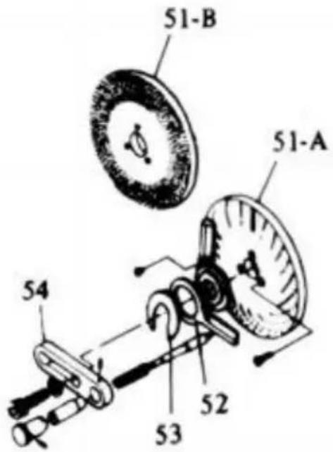
natural_image
Mechanical diagram showing a flanged component connected to a rotating wheel assembly (no text or labels)
natural_image
Mechanical diagram of a wheel and linkage mechanism with rotational arrow (no text or labels)Fikon 5
Fikon 6

natural_image
Mechanical diagram showing a rotating disk with a lever and rotating shaft (no text or symbols)Fig 7

natural_image
Diagram of a mechanical device with rotating components and directional arrows indicating motion (no text or labels)Fikon 8
En tallrik 26,28, 30,32,34,37,38,39,41,43,44,46,47,49,51,53,57,59
B Tallrik 61,63,6 7,69,71,73,77,79,81,83,87,89,91,93,97,99
DELLISTA
Modell : HV-4-KP
Place, Rancho Cucamonga, CA 91730
| EC | REP |
SHUNSHUN GmbH
Römeräcker 9 Z2021, 76351 Linkenheim-
Hochstetten, Germany
| UK | REP |
Pooledas Group Ltd
Unit 5 Albert Edward House, The
Pavilions Preston, United Kingdom
Tillverkad i Kina
VEVOR®
TOUGH TOOLS, HALF PRICE


