USER MANUAL GT-1200 Vevor
MICRO INVERTER
MODEL: GT-600/GT-800/GT-1200
We continue to be committed to providing you with tools at competitive prices. "Save Half", "Half Price", or any other similar expressions used by us only represent an estimate of savings you might benefit from buying certain tools with us compared to top brands, and does not necessarily mean to cover all categories of tools offered. We kindly remind you to verify carefully when placing an order with us to ensure you are actually saving half in comparison with the top major brands.
MODEL: GT-600/GT-800/GT-1200
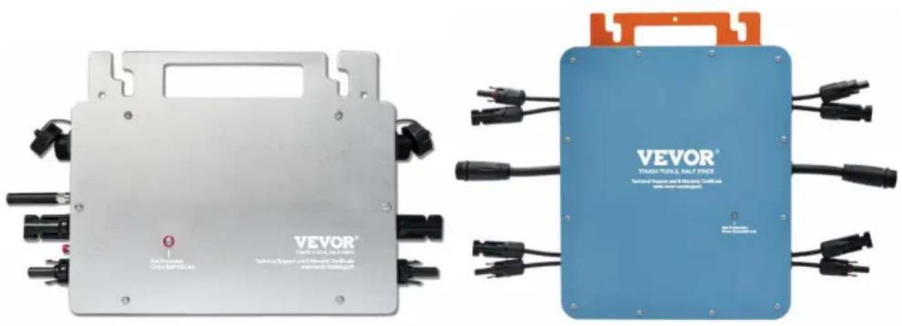
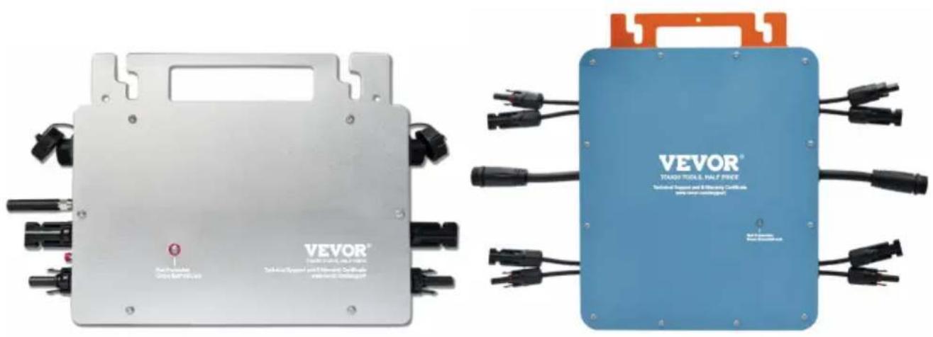
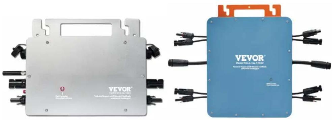
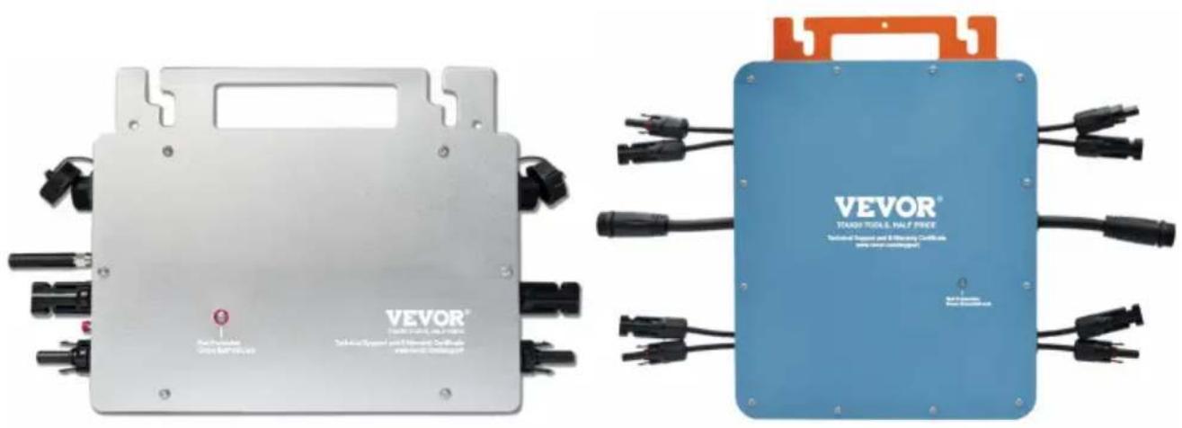
GT-600/GT-800 GT-1200
Have product questions? Need technical support? Please feel free to contact us:
This is the original instruction. Please read all manual instructions carefully before operating. VEVOR reserves the right to interpret the user manual. The appearance of the product shall be subject to the product you received. Please forgive us that we won't inform you of any technology or software updates on our product.
 | Warning-To reduce the risk of injury, user must read in manual carefully. |
 | This product is subject to the provision of European Dir 2012/19/EC. The symbol showing a wheelie bin crossed through indicates that the product requires separate refus collection in the European Union. This applies to the pr and all accessories marked with this symbol. Products n as such may not be discarded with normal domestic wa must be taken to a collection point for recycling electric electronic devices |
WARNING: DANGER OF ELECTRICAL SHOCK
The product is used in combination with a permanent energy source (battery). Even if the equipment is switched off, a dangerous electrical voltage can occur at the input and/or output terminals. Always switch the AC power off and disconnect the battery before performing maintenance.
The product contains no internal user-serviceable parts. Do not remove the front panel and do not put the product into operation unless all panels are fitted. All maintenance should be performed by qualified personnel.
Never use the product at sites where gas or dust explosions could occur. Refer to the specifications provided by the manufacturer of the battery to ensure that the battery is suitable for use with this product. The battery manufacturer's safety instructions should always be observed.
WARNING: do not lift heavy objects unassisted.
Installation
Read the installation instructions before commencing installation activities. This product is a safety class I device (supplied with a ground terminal for safety purposes). Its AC input and/or output terminals must be provided with uninterruptible grounding for safety purposes. An additional ground point is located on the outside of the product. If it can be assumed that grounding protection is damaged, the product should be taken out of
operation and prevented from accidentally being put into operation again. Contact qualified maintenance personnel.
Ensure that the connection cables are provided with fuses and circuit breakers. Never replace a protective device by a component of a different type. Refer to the manual for the correct part.
Check before switching the device on whether the available voltage conforms to the configuration settings of the product as described in the manual.
Ensure that the equipment is used under the correct operating conditions. Never operate it in a wet or dusty environment.
Ensure that there is always sufficient free space around the product for ventilation, and that ventilation openings are not blocked.
Install the product in a heatproof environment. Ensure therefore that there are no chemicals, plastic parts, curtains or other textiles, etc.
in the immediate vicinity of the equipment.
Transport and storage
On storage or transport of the product, ensure that the mains supply and battery leads are disconnected.
No liability can be accepted for damage in transit if the equipment is transported in its original packaging.
Store the product in a dry environment; the storage temperature should range from -40°C to 65°C.
Refer to the battery manufacturer's manual for information on transport, storage, charging, recharging and disposal of the battery.
SPECIFICATIONS
You are welcome to choose our micro grid-connected solar inverter products
| Specification data | Model |
| GT-600 | GT-800 | GT-1200 |
| Input Data (DC, PV) |
| Number of Input MC4 Connect | 2 sets | 4 sets |
| Operation Voltage Range | DC18V-50V |
| Maximum input Current | 12A*2 | 14A*2 | 16A*2 |
| Output Data(AC) |
| Single-Phase Grid Type | AC230V | AC230V | AC110V or AC230V |
| Maximum Output Power | 600W | 800W | 1200W |
| Nominal Output Current | 2.6A | 3.5A | 10.9A or 5.2A |
| Nominal Output Voltage | AC230V | AC230V | AC110V or AC230V |
| Output Frequency Range | 50Hz | 50Hz | 60Hz or 50Hz |
| Power Factor | ≥0.99% |
| Total Harmonic Distortion | THD <5% |
| Maximum Units per Branch | @230VAC:4units | @230VAC:3units | @110VAC:2units Or @230VAC:3units |
| Peak Efficiency | 95% |
| Nominal MPPT Efficiency | 99.5% |
| Night Power Consumption | ≤1W |
| Mechanical Data |
| Operating Ambient Temperature Range | -40°C to +65°C |
| Storage Temperature Range | -40°C to +85C |
| Dimensions(W*H *D) | 305 * 186 * 44mm | 490 * 254 * 50mm |
| Waterproof Grade | IP67 | IP65/IP67(Please refer to the product nameplate information) | IP67 |
| Communication | WIFI(Cloud monitoring) |
| Protection Functions | Isolated Island Protection,Voltage ProtectionFrequency ProtectionTemperature Protection,Current Protection, etc. |
INSTALLATION SCHEMATIC
Single-phase parallel assembly method of micro inverter
GT-600![graph LR A["1"] --> B["2"] B --> C["3"] C --> D["4"] style A fill:#f9f,stroke:#333 style B fill:#ccf,stroke:#333 style C fill:#cfc,stroke:#333 style D fill:#fcc,stroke:#333](/content/2026/04/735589/images/5b80910cdca0981cd296eb27f76428567266bdb34f607fa4c168b99b53e40271.jpg)
- @Single-Phase 230V grid Maximum 4 units 600W Micro inverters per branch
- The max DC input power of each inverter is 600W (the PV module max power is 2x300W).
- The VOC of PV modules should not be greater than the max DC input of Micro inverters.
GT-800![graph LR A["1"] --> B["2"] B --> C["3"] style A fill:#f9f,stroke:#333 style B fill:#bbf,stroke:#333 style C fill:#dfd,stroke:#333](/content/2026/04/735589/images/9cb0ba023b811da1b69a4ca0e58e86bb5902d287fc6fbc58b6e31688ce92d223.jpg)
- @Single-Phase 230V grid Maximum 3 units 800W Micro inverters per branch
- The max DC input power of each inverter is 800W (the PV module max power is 2x400W).
- The VOC of PV modules should not be greater than the max DC input of Micro inverters.
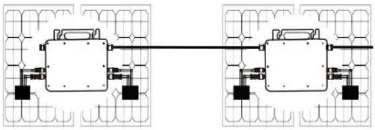
GT-1200
1 2
- @Single-Phase 110V grid Maximum 2 units or @Single-Phase 230V grid Maximum 3 units 1200W Micro inverters per branch.
- The max DC input power of each inverter is 1200W (the PV module max power is 2x600W).
- The VOC of PV modules should not be greater than the max DC input of Micro inverters.
WIRING SCHEMATIC
![graph LR subgraph GT-600/GT-800 A["Component 1"] --> B["Component 2"] C["Component 3"] --> D["Component 4"] E["Component 5"] --> F["Component 6"] G["Component 7"] --> H["Component 8"] I["Component 9"] --> J["Component 10"] K["Component 11"] --> L["Component 12"] M["Component 13"] --> N["Component 14…](/content/2026/04/735589/images/004d5080a86a57aa96bb758c9a0d9631681e6ded02a62ef2f5e67f9e01098971.jpg)
Three phase connection method of micro inverter
GT-600/GT-800![graph TD A["On-Grid Grid"] --> B["Ground"] B --> C["PV Array A"] B --> D["PV Array B"] B --> E["PV Array C"] style A fill:#f9f,stroke:#333 style B fill:#ccf,stroke:#333 style C fill:#cfc,stroke:#333 style D fill:#fcc,stroke:#333 style E fill:#cff,stroke:#333](/content/2026/04/735589/images/a0079c0ed83e3fd0d1923b89a296d3df3aab701826818eda6b912f002f887a99.jpg)
GT-1200![graph TD A["On-Grid"] --> B["Ground"] B --> C["PV Array A"] B --> D["PV Array B"] B --> E["PV Array C"] C --> F["Grid Connection"] D --> F E --> F F --> G["Ground"]](/content/2026/04/735589/images/f47f720717b77e02a8dbf58accdb0c22b1aacf6b93483b4e4d30be5da941d9b5.jpg)
MICRO INVERTER WIFI CLOUD MONITORING
1. Precautions
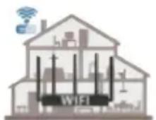
● Note that there is a risk of electric shock when connecting the micro-inverter! ● The micro-inverter heats up during operation! Protect yourself accordingly from burns! - Before configuring WiFi cloud monitoring, please correctly install the micro inverter and make it work normally. - A smart device (smartphone or tablet) with Bluetooth function and Android or iOS system and a wireless network device (e.g., wireless router) that can provide WiFi and Internet service must be available. - To configure WLAN cloud monitoring, first switch on the Bluetooth function of the smart device. - Make sure that your smart device uses the same WiFi network as the micro inverter to be configured and that it can connect to wireless network devices and access the internet in the same location of the micro inverter. ● Make sure that the distance between the wireless network device and the micro-inverter does not exceed 20 m and that there are no or few obstacles.
2. Hardware Description
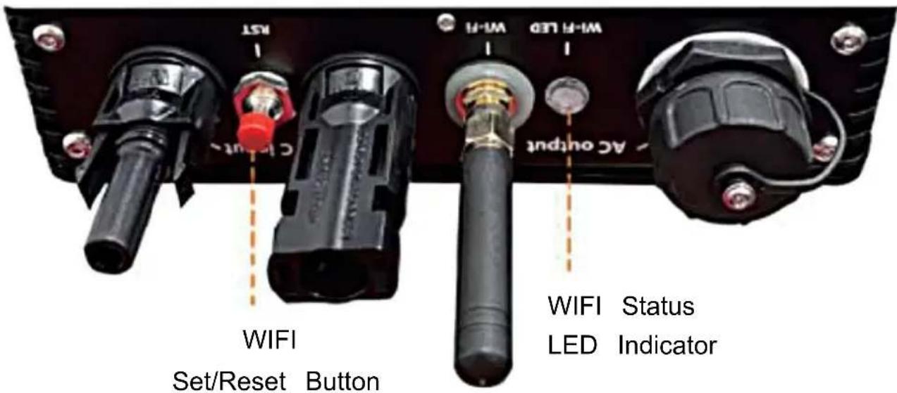
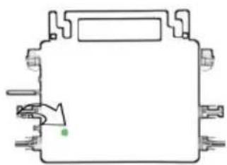
3. WIFI Status LED
- The blue light flashes after always on = the WiFi cloud monitoring module is waiting for configuration.
- The blue light off after always on = the WiFi cloud monitoring module starts and enters the normal working state.
- The blue light flashes = the network is not configured or the network cannot connect to the wireless network device, or the micro inverter has been deleted in the cloud.
- No light = WiFi cloud monitoring is working normally.
4. Preparation Before Configuration And Use
- Install the micro inverter correctly and make it work normally to generate power.
- Download and install the "Smart Life" app by searching for it in the corresponding Android or Apple app store.
- Turn on the Bluetooth function of your smart device.
- Check that your wireless network device (such as a wireless router) is working properly and connected to the Internet.
- Use your smart device (or the "Smart Life" app installed) at the installation location of the micro inverter to connect to the wireless network device. If you can access the Internet normally, follow the instructions for configuration and usage on the next page.



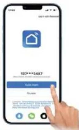
5. Configuration Steps of WiFi Cloud Monitoring.


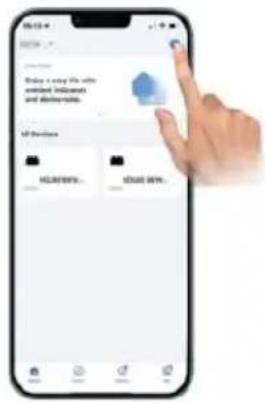
1
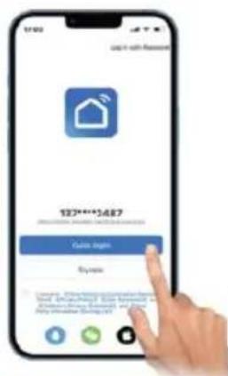
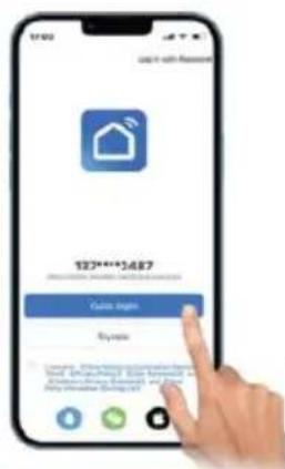
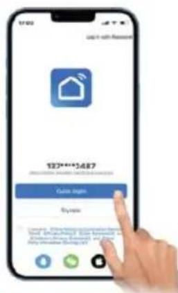
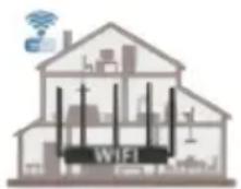
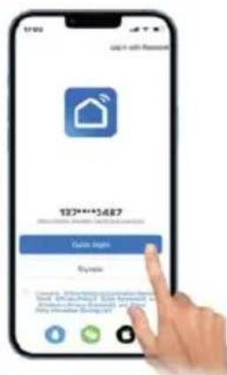
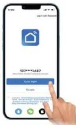
Download the mobile application: Smart Life or scan the QR code directly.
2
Register a personal account.
3
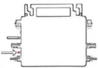
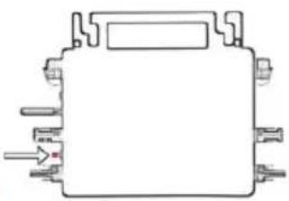
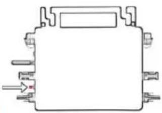
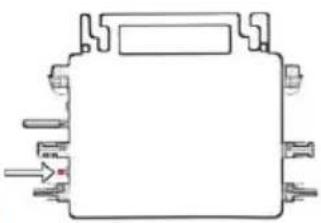
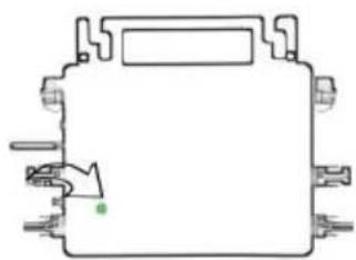
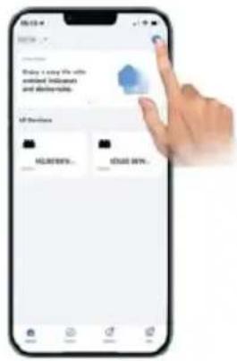
Restore factory settings: Press and hold the red key for 5-10 seconds and release it. The blue light flashes and the device is connected successfully.
4
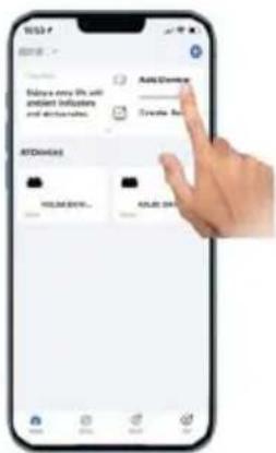
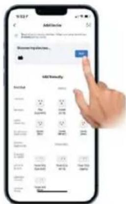
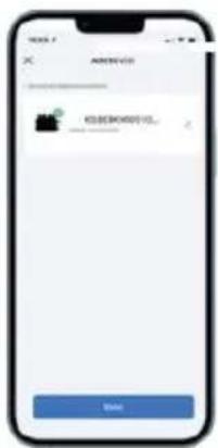
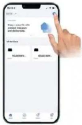
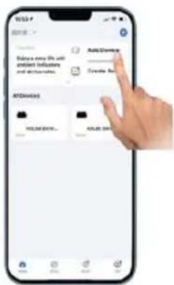
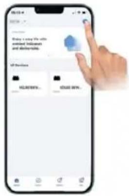
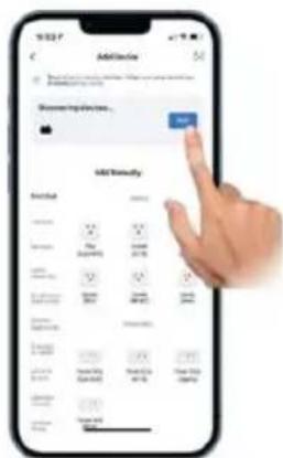
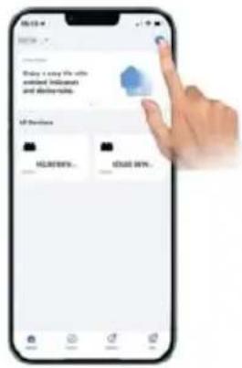
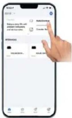
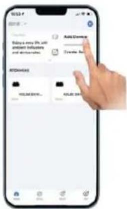
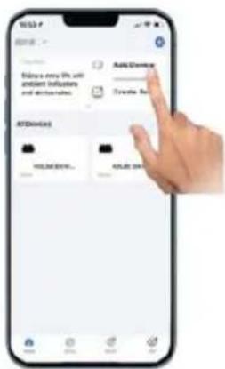
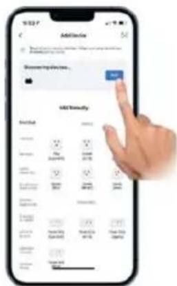
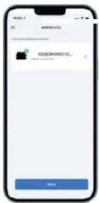
Add inverter.
5
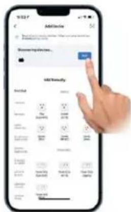
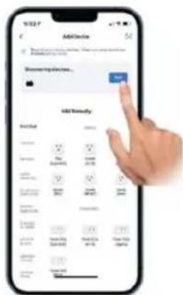
Further add confirmation information
6
Make sure the Bluetooth or Wi-Fi on the phone is on
7
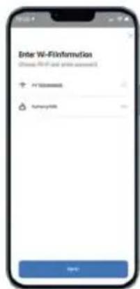
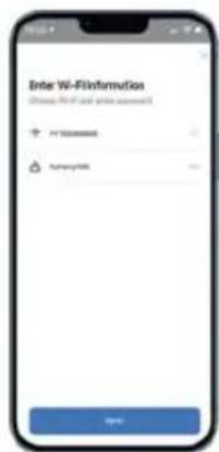
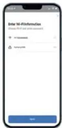
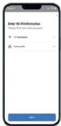
Enter your home Wi-Fi account information and password
8
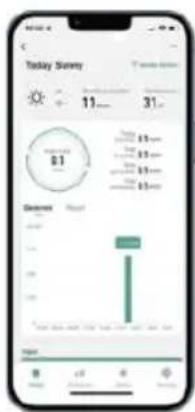
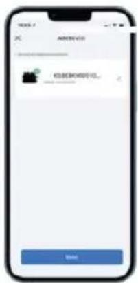
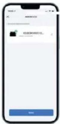
Click Next to install and modify the name and account freely
9
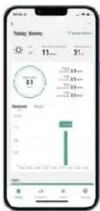
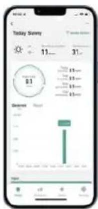
The interface can control the system switch normally. The connection is successful
10
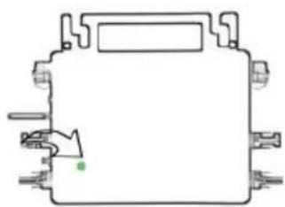
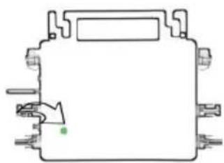
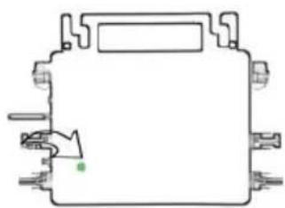
10 The connection is successful, and the green light of the inverter is always on in normal operation. Occasionally flashing instrument MPPT is tracking the optimal voltage
6. Usage of Wi-Fi Cloud Monitoring App.
Modify Device Name
- Click the device to be modified in the device list on the home page to enter the device information details page (Figure 5).
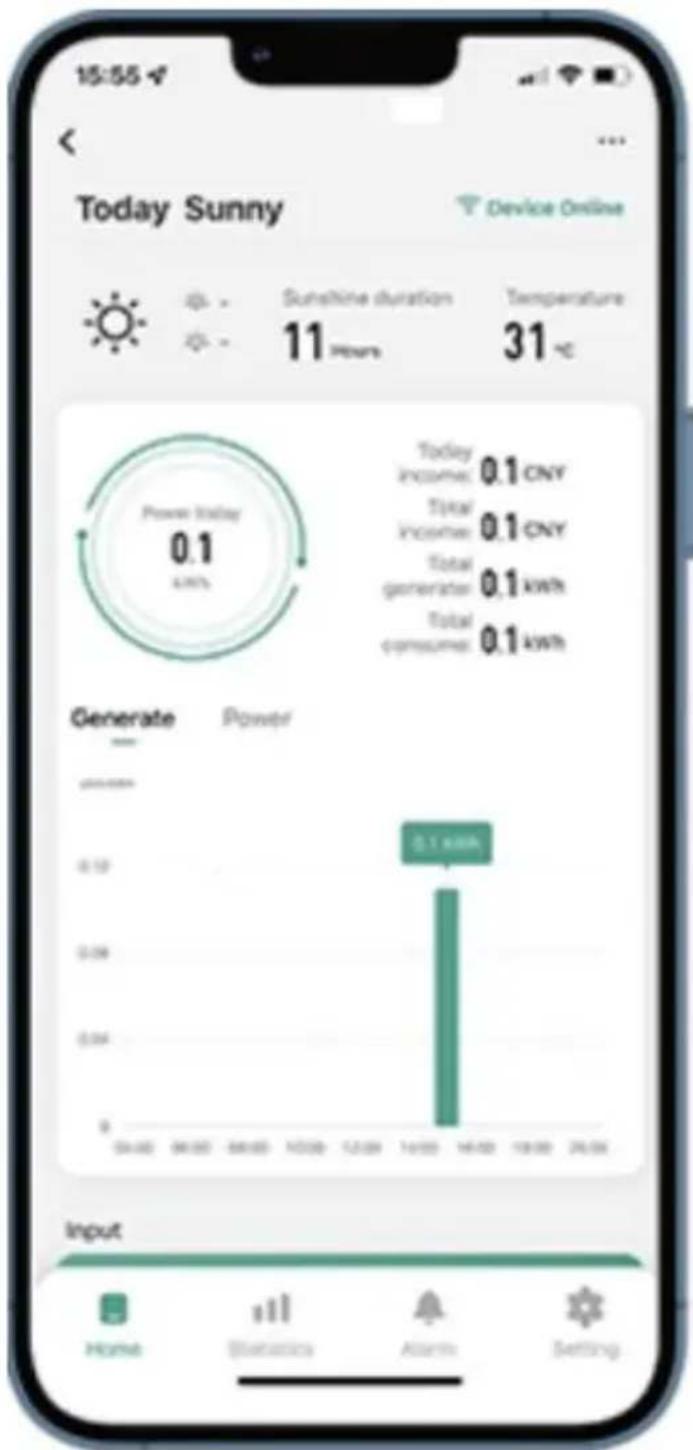
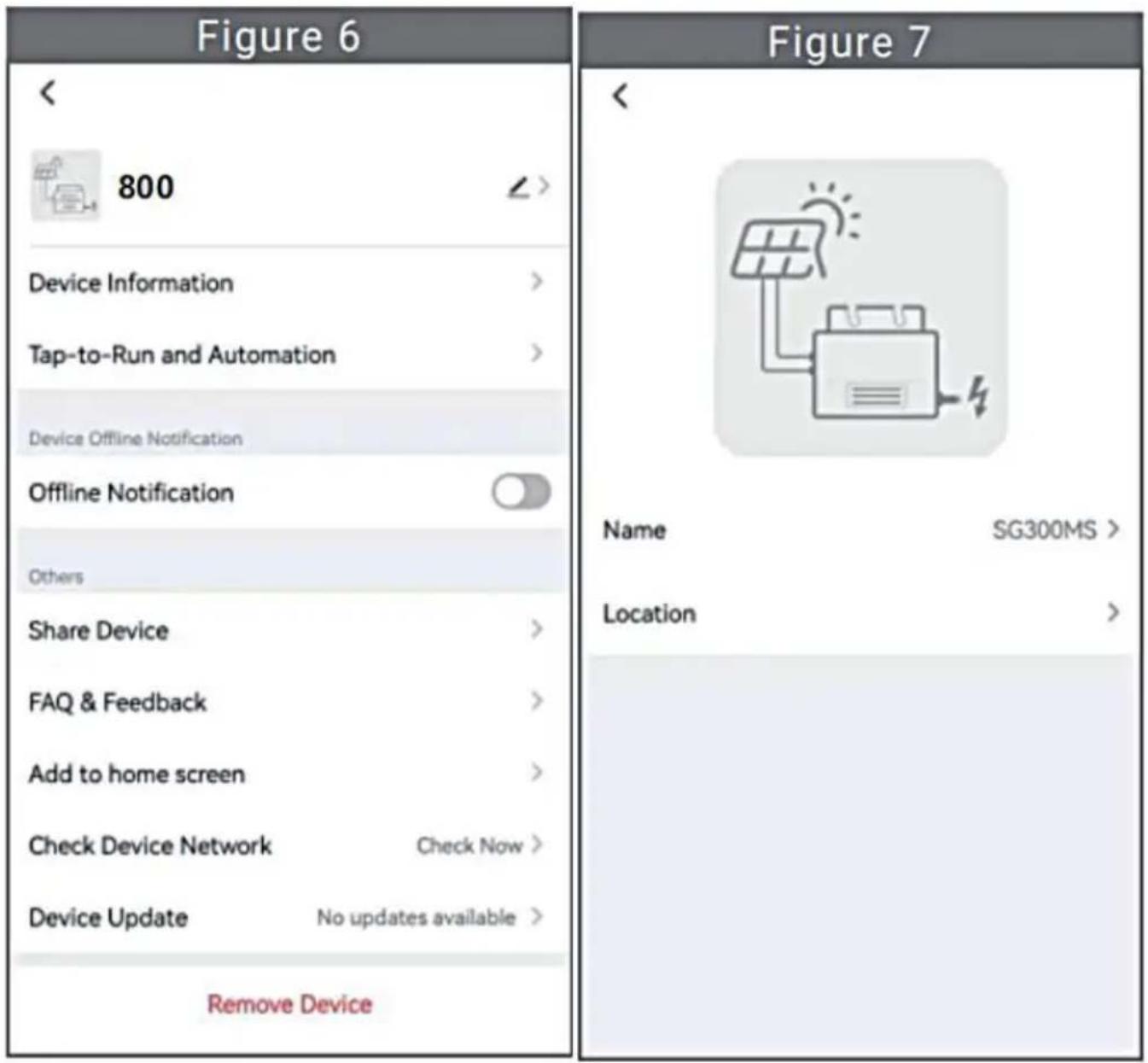
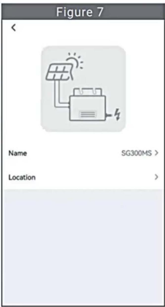
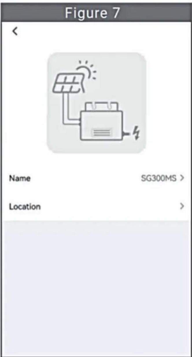
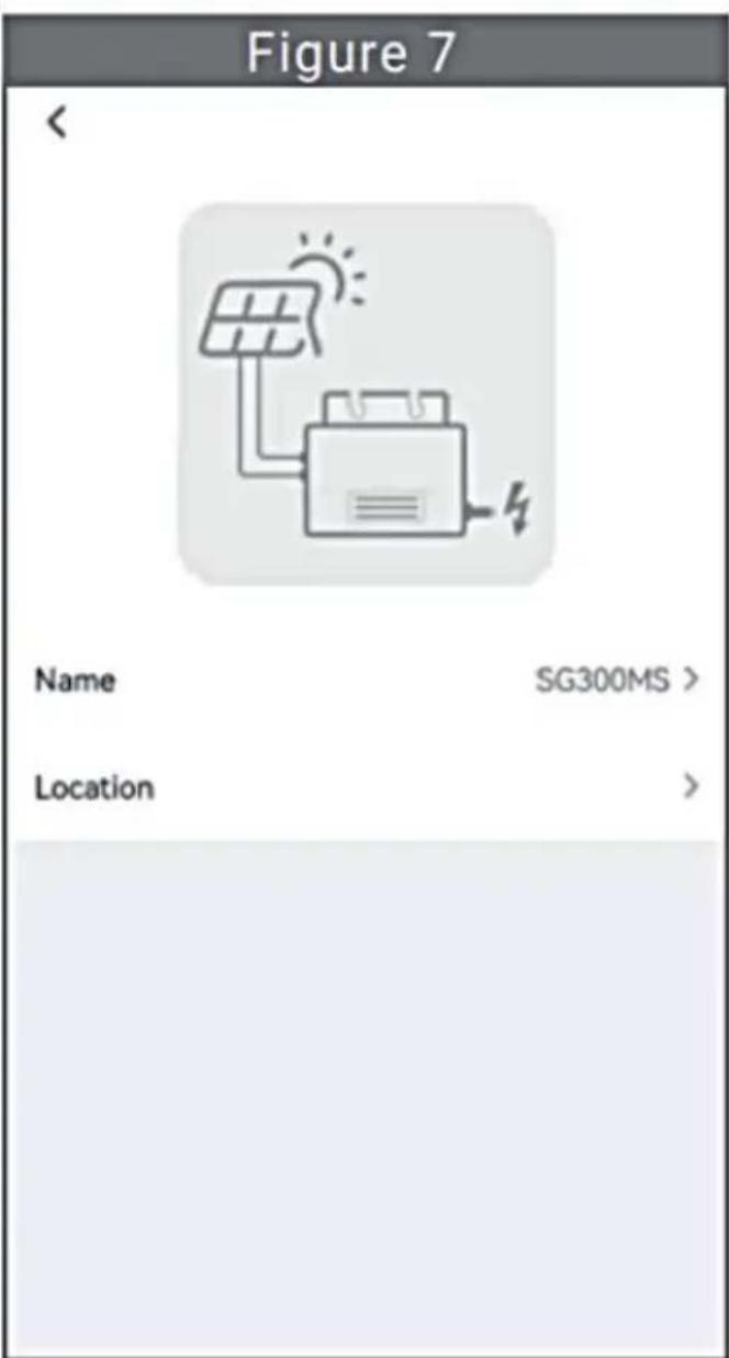
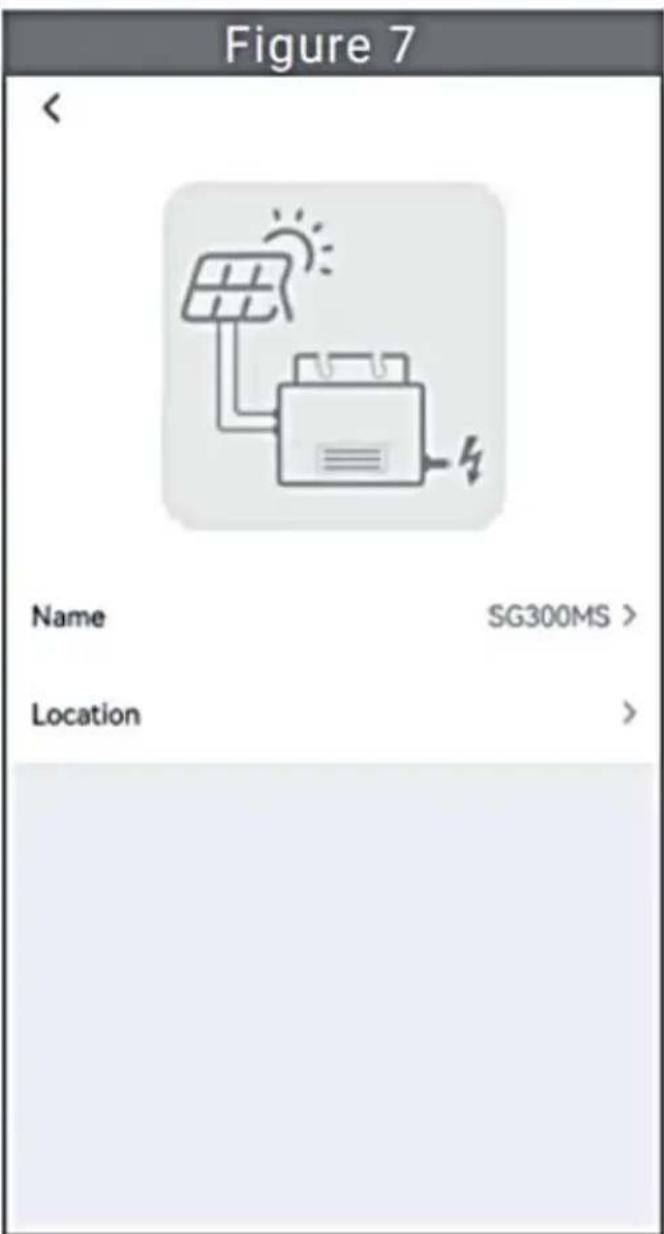
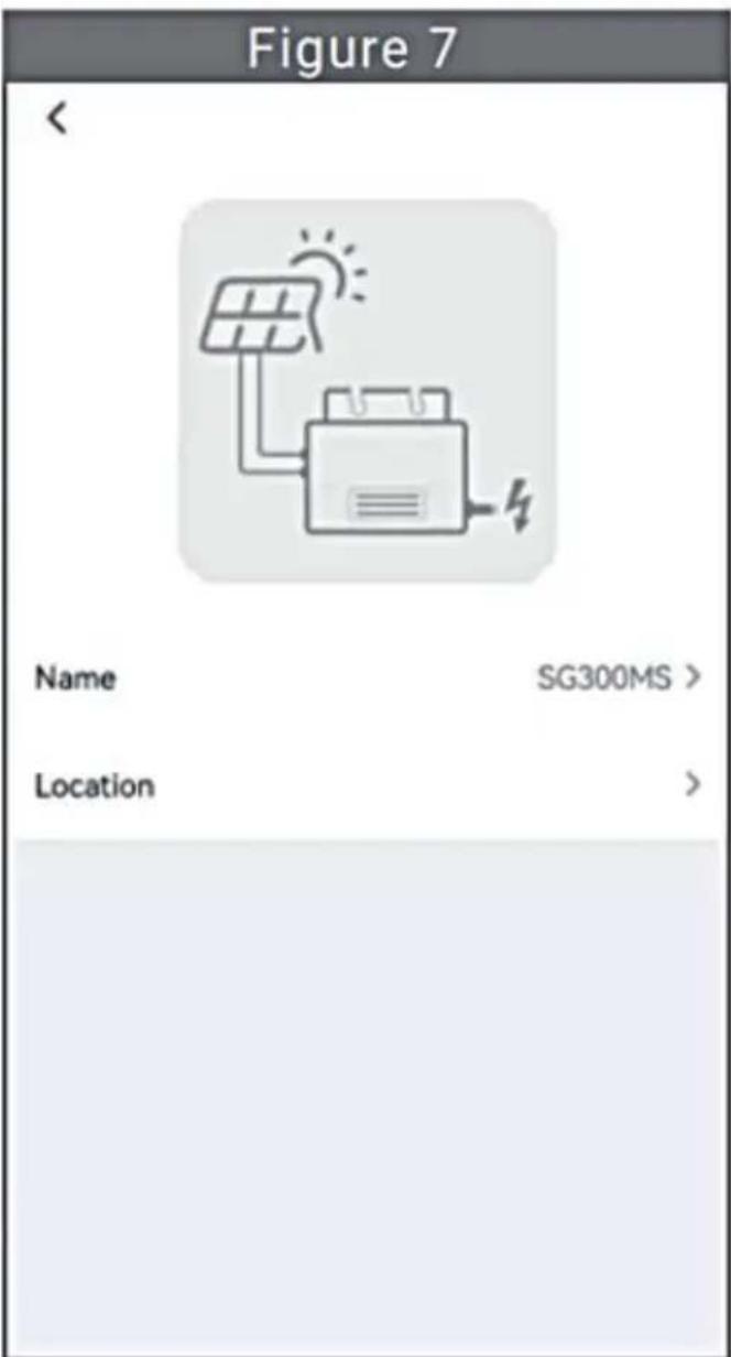
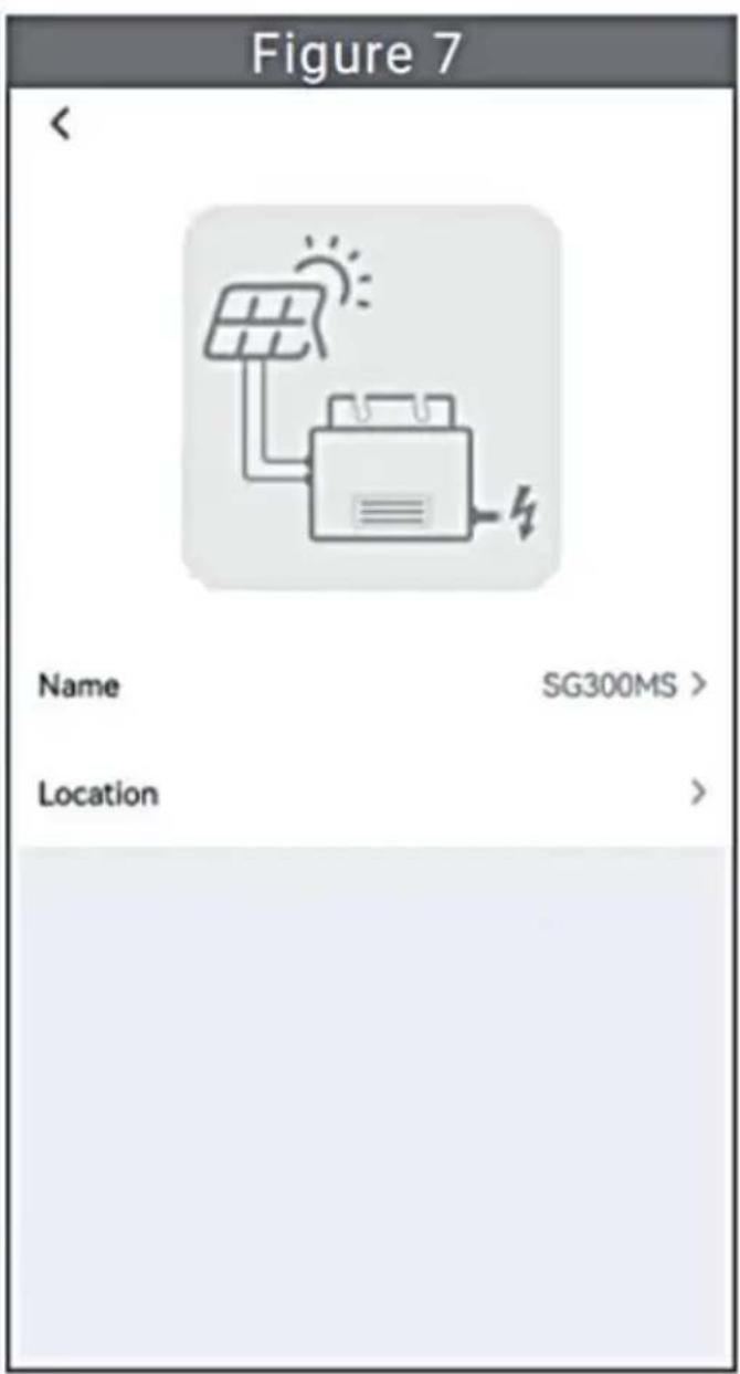
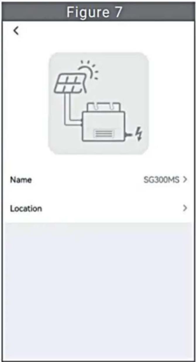
- Click the button in the upper right to enter the device setting page (Figure 6), continue to click the upper button to the page of name & position (Figure 7), click the name item, then enter a new name and save (Figure 8).
Remove Device
- Click the device to be deleted in the device list on the home page to enter the device information details page (Figure 5).
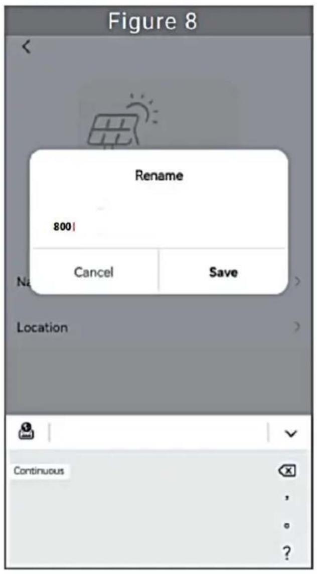
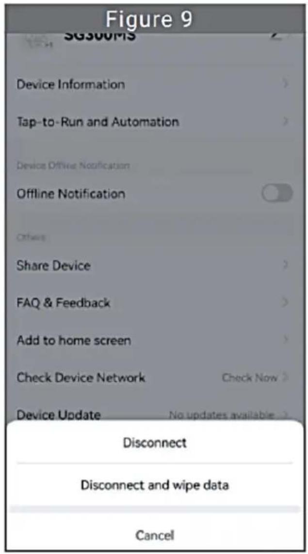
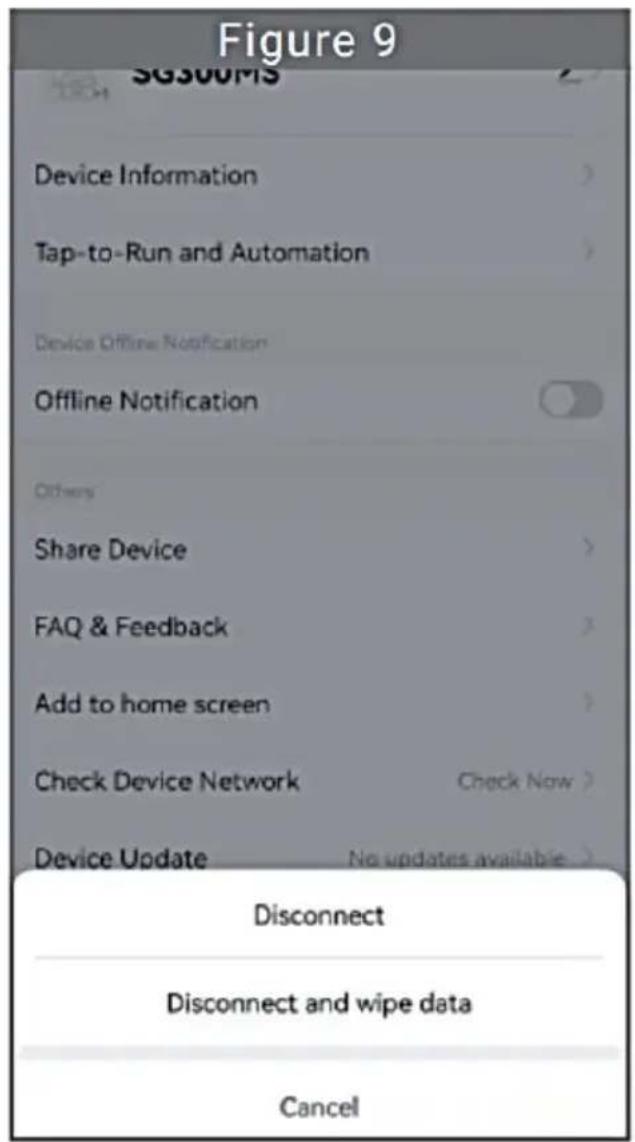
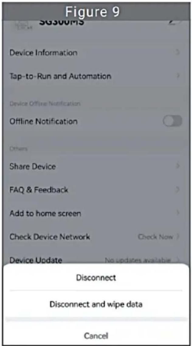
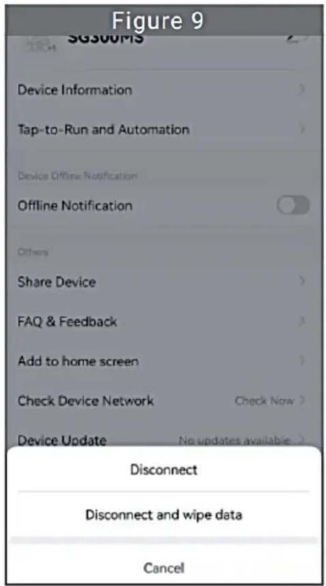
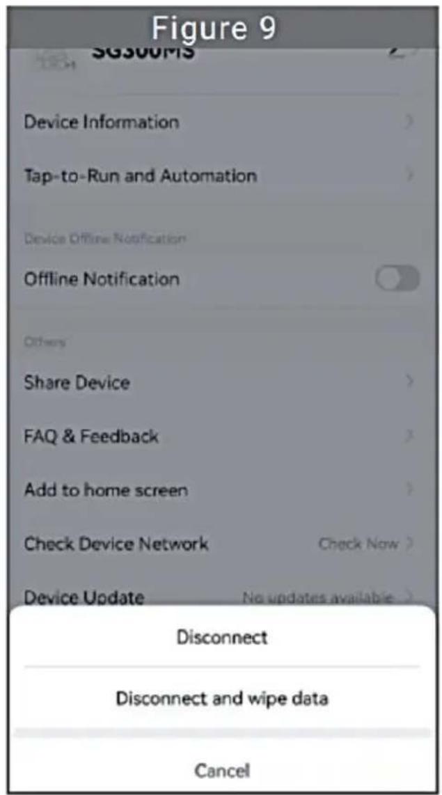
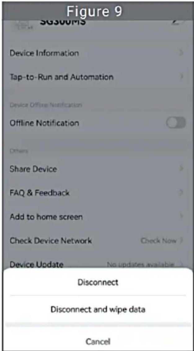
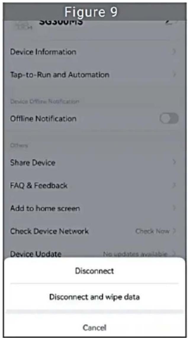
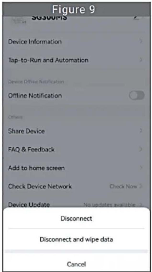
- Click the button in the upper right to enter the device setting page (Figure 6). Click "Remove Device" button below (Figure 9), click the "Disconnect" button to remove the device or click the "Disconnect and wipe data" button to remove the device and clear all data saved by the device in the cloud at the same time.
Share Device With Others
- Click the device to be shared in the device list on the home page to enter the device information details page (Figure 5).
- Click the button in the upper right to enter the device setting page (Figure 6).
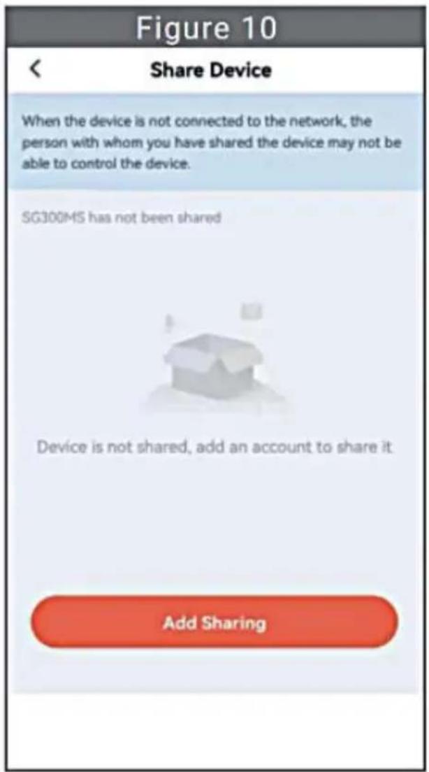
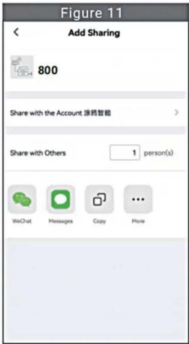
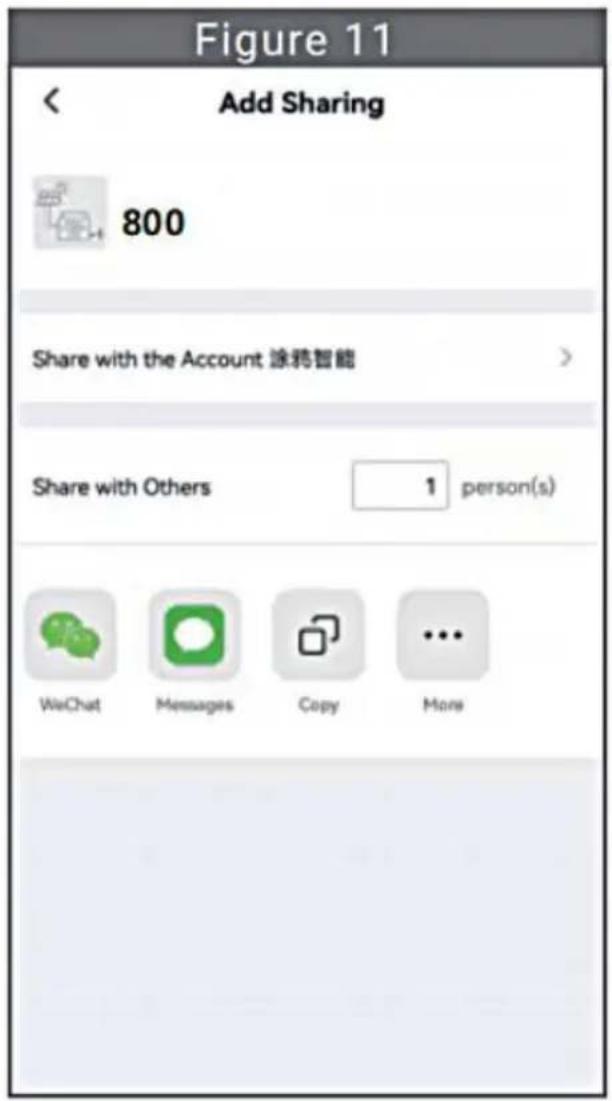
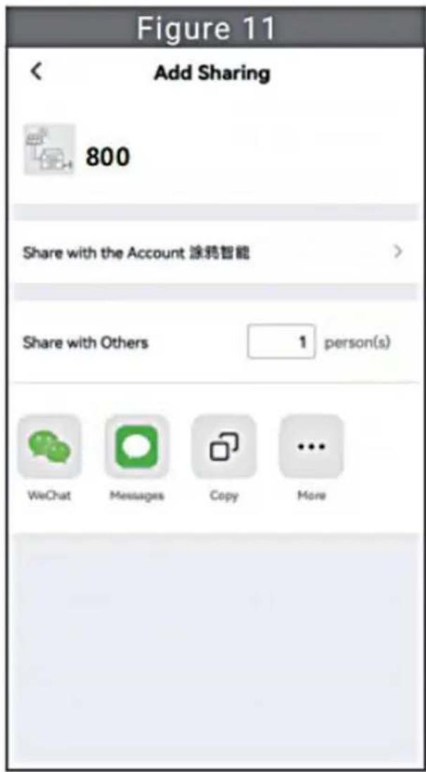
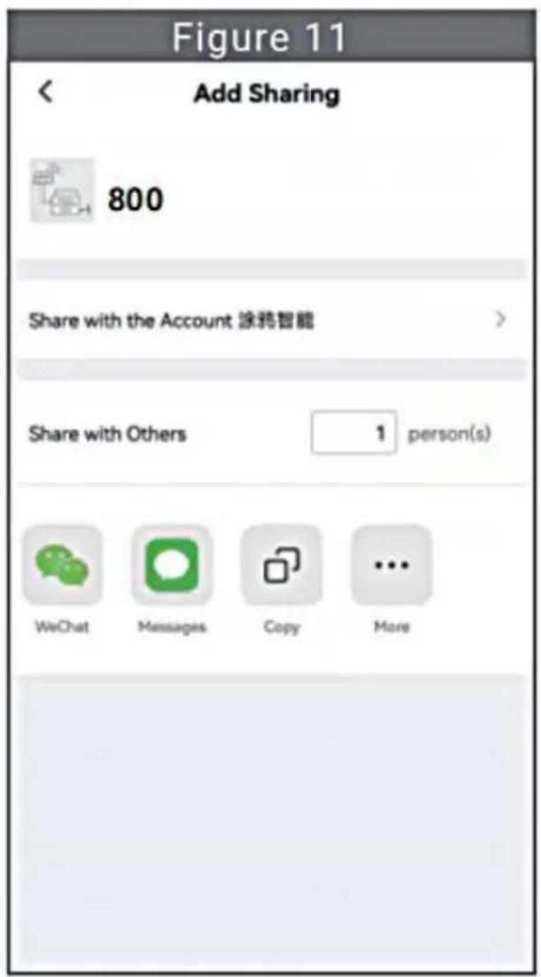
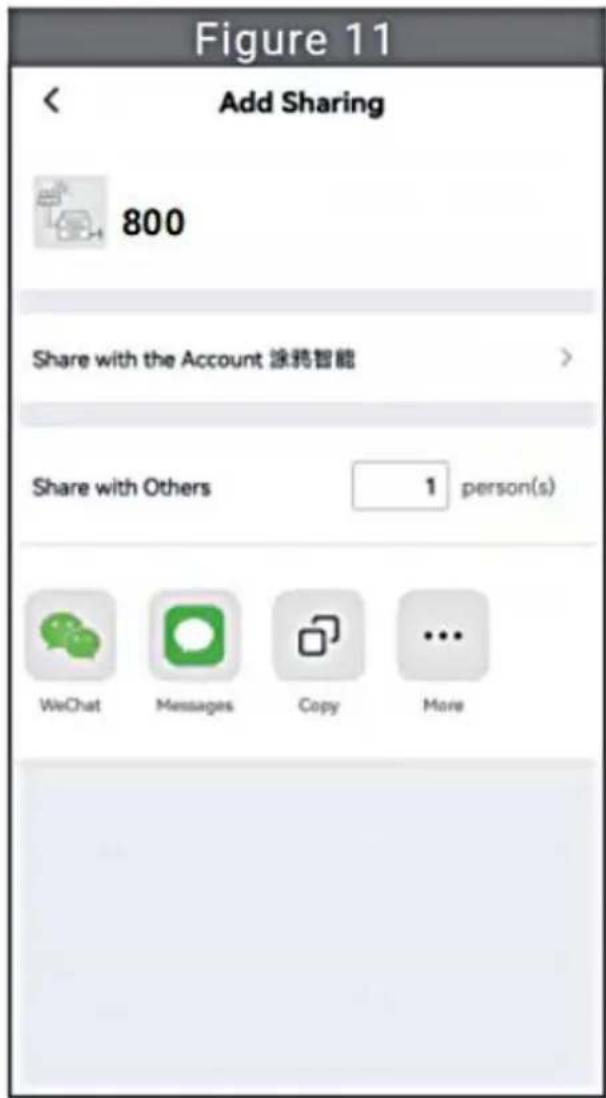
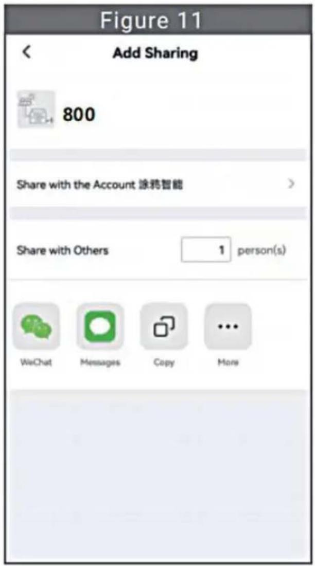
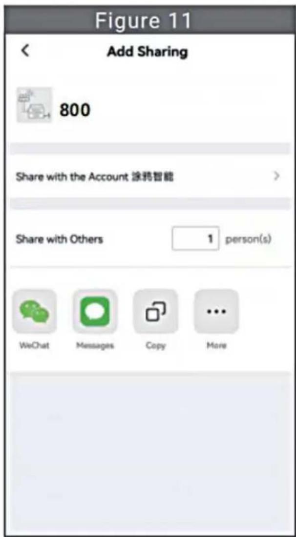
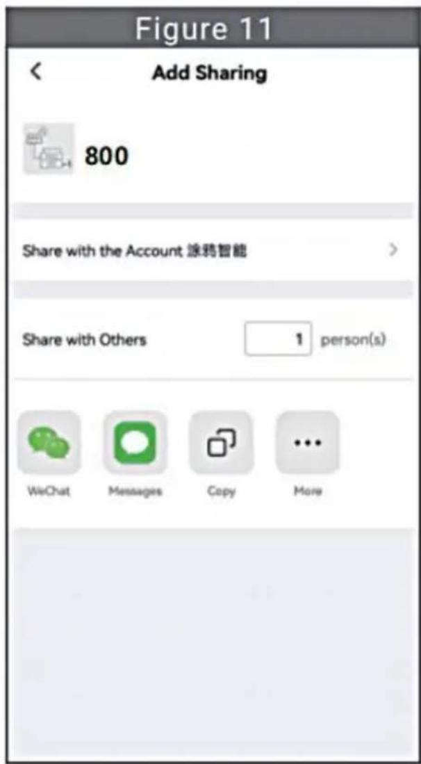
- Click the "Share Device" item to enter the device sharing page (Figure 10), click button to enter "Add Sharing" page (Figure 11), and select the best sharing way that you think is most convenient to share the link of micro inverter.
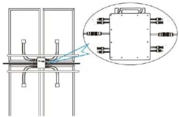
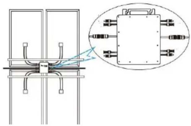
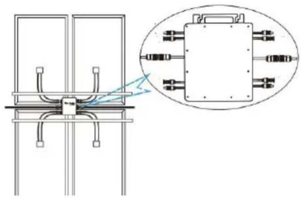
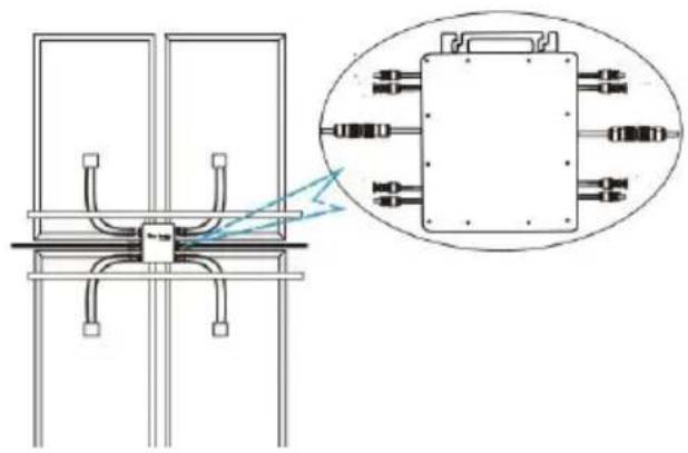
- The installation process of fixing inverter to PV bracket with mounting screws is as follows:

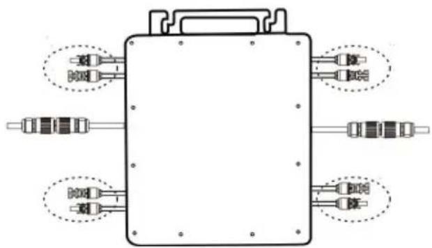
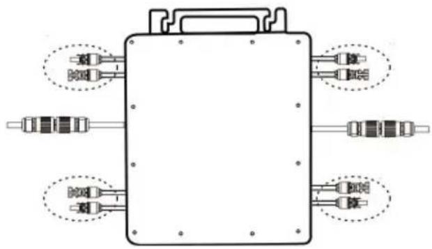
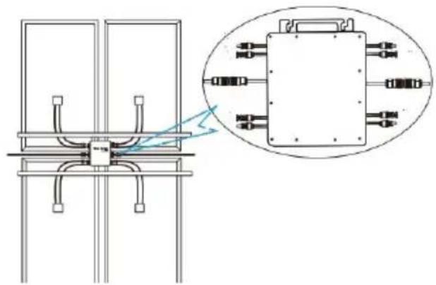
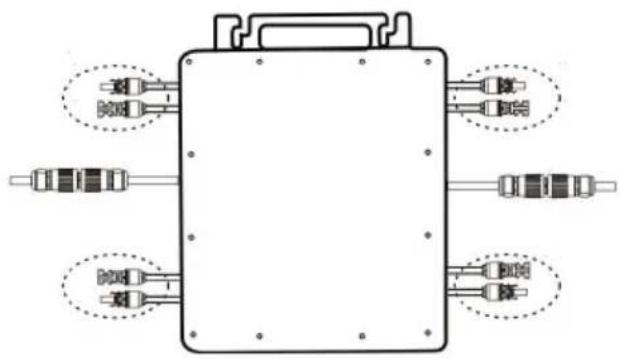
- Connect the DC of PV to the inverter, and pay attention to distinguish between positive and negative, as shown below:
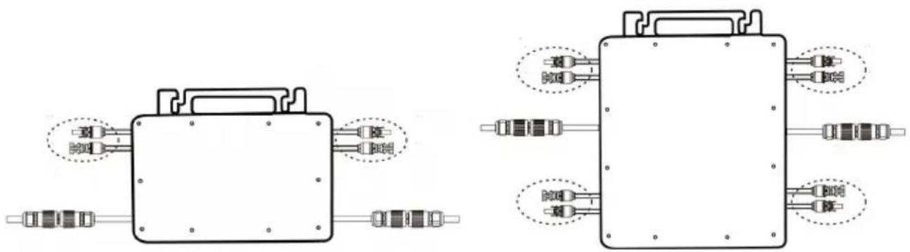
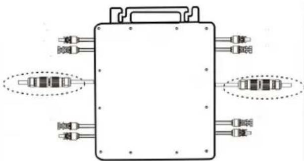
GT-600/800 GT-1200
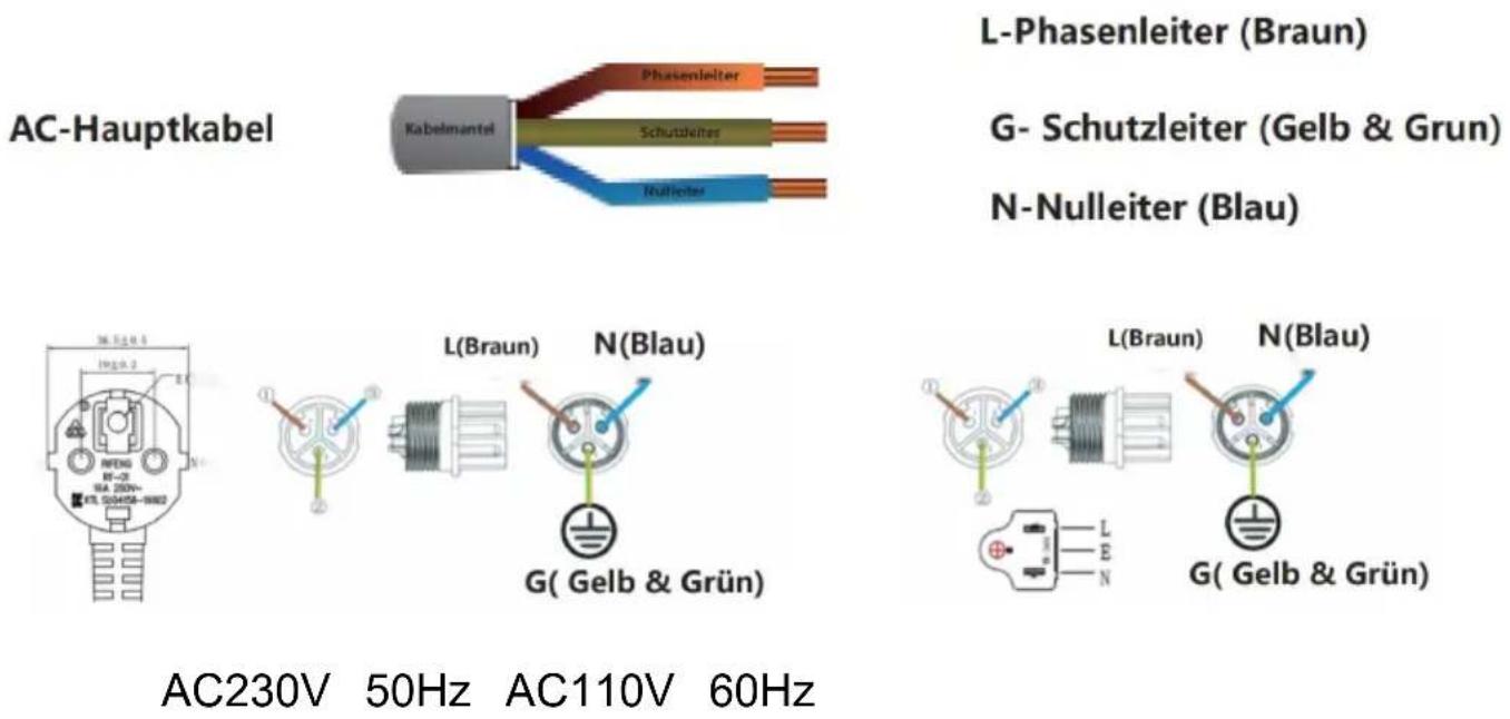
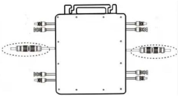
- Open the waterproof cover on the AC output side of the micro inverter, and then connect it to the AC. As follows:

- Repeat steps 1 to 3 to complete the installation of the micro inverter.
- Connect multiple inverters through AC output cables.
- The AC main cable is connected to the power grid.
SCHEMATIC DIAGRAM OF THE COMPLETION OF THE INSTALLATION![graph TD A["Power Transmission System"] --> B["Sensor"] B --> C["Sensor Tracking System"] C --> D["Mobile Payment System"] D --> E["Wireless Device"] E --> F["Power Supply"] style A fill:#f9f,stroke:#333 style B fill:#ccf,stroke:#333 style C fill:#cfc,stroke:#333 style D fill:#fcc,stroke:#333 style…](/content/2026/04/735589/images/ae997fdc5a8731a60ef70f7346d15f59d7ed772bb7884ce8bf58c75eac8fcdb1.jpg)
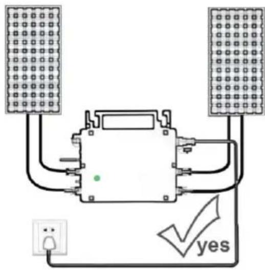
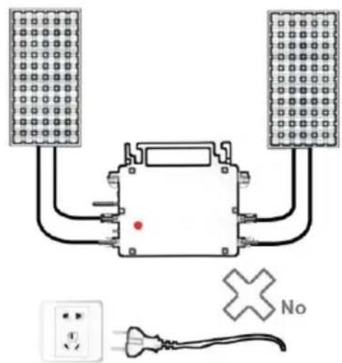
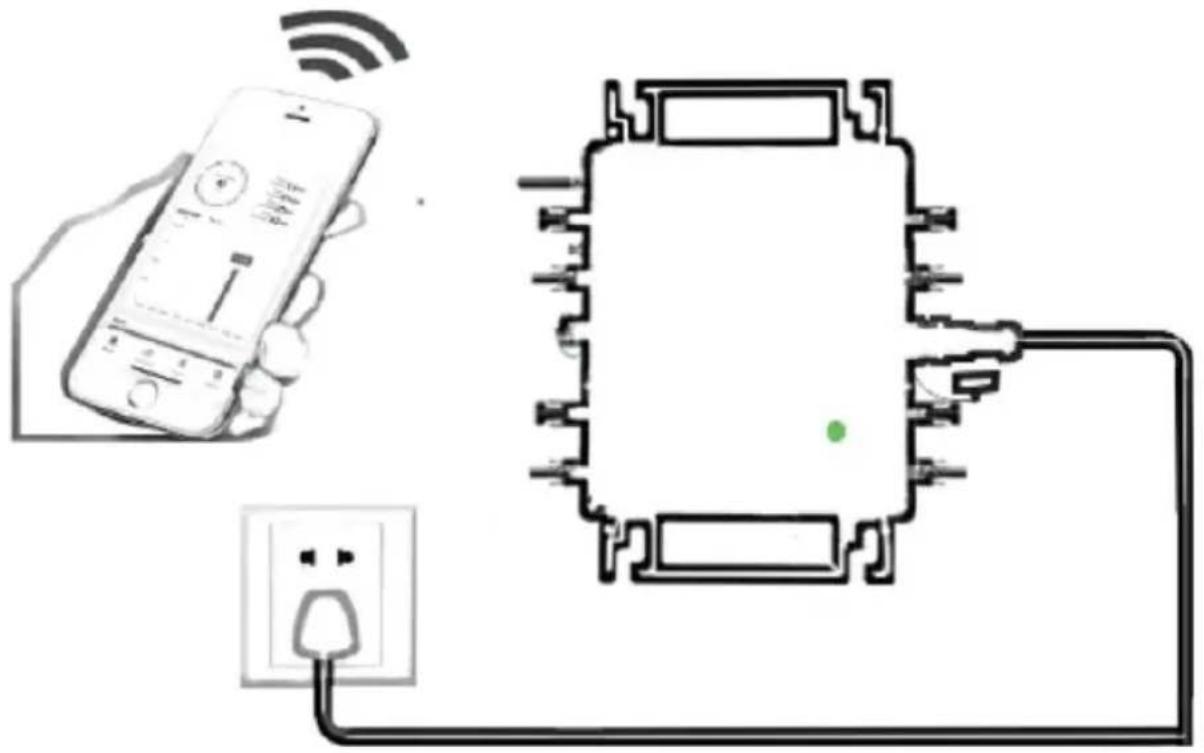
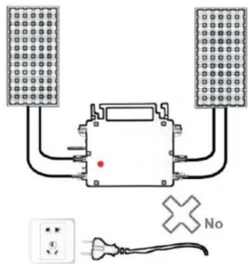
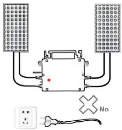
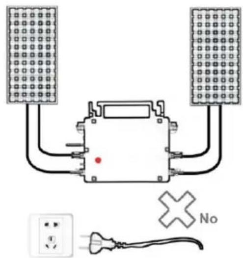
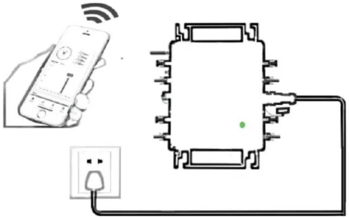
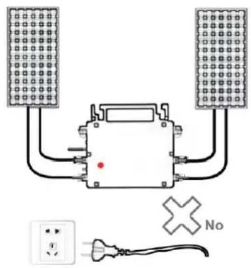
Normal working conditions of the inverter: the 22-50V DC voltage of the solar panel must be connected, and the AC voltage must be connected at the same time, and the indicator light is green. Only the solar panel is connected. When the mains AC is not connected, the red light on the inverter surface is on, and the instrument and machine do not work normally.
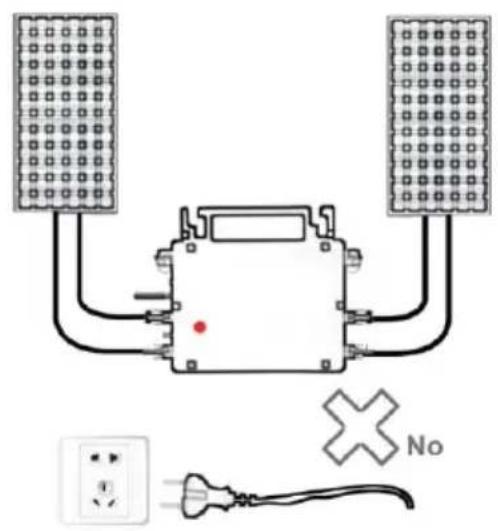
GT-600/800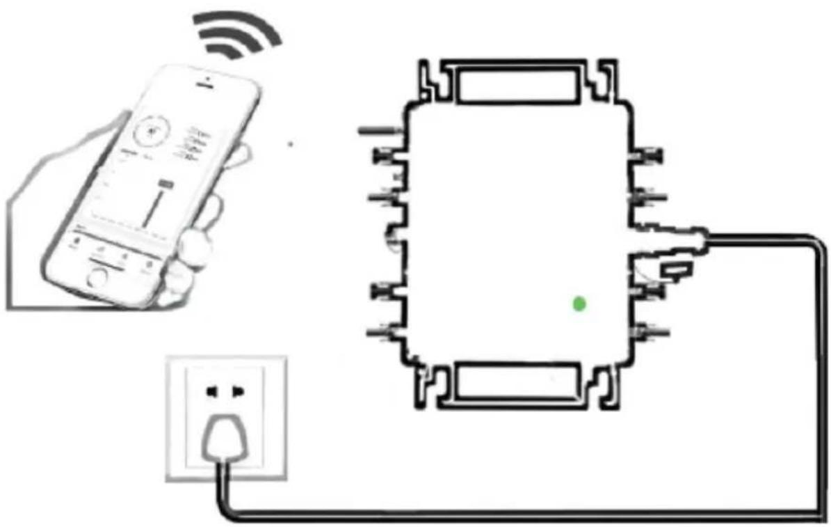
![graph TD A["Power Source"] --> B["Central Device"] C["Solar Panel 1"] --> B D["Solar Panel 2"] --> B E["Solar Panel 3"] --> B F["Solar Panel 4"] --> B B --> G["Output"] style B fill:#f9f,stroke:#333,stroke-width:2px note right of B: ✓ yes](/content/2026/04/735589/images/2797879af6ba55b562a837acfc6c0137222ca1d7416ff2c05c4f21069eb482af.jpg)
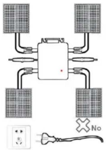
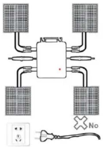
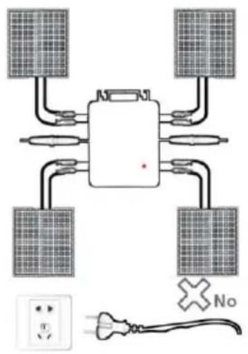
Normal working conditions of the inverter: the 22-50V DC voltage of the solar panel must be connected, and the AC voltage must be connected at the same time, and the indicator light is green. Only the solar panel is connected. When the mains AC is not connected, the red light on the inverter surface is on, and the instrument and machine do not work normally.
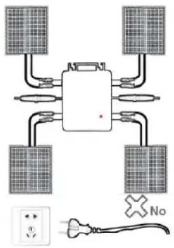
GT-1200
Note:
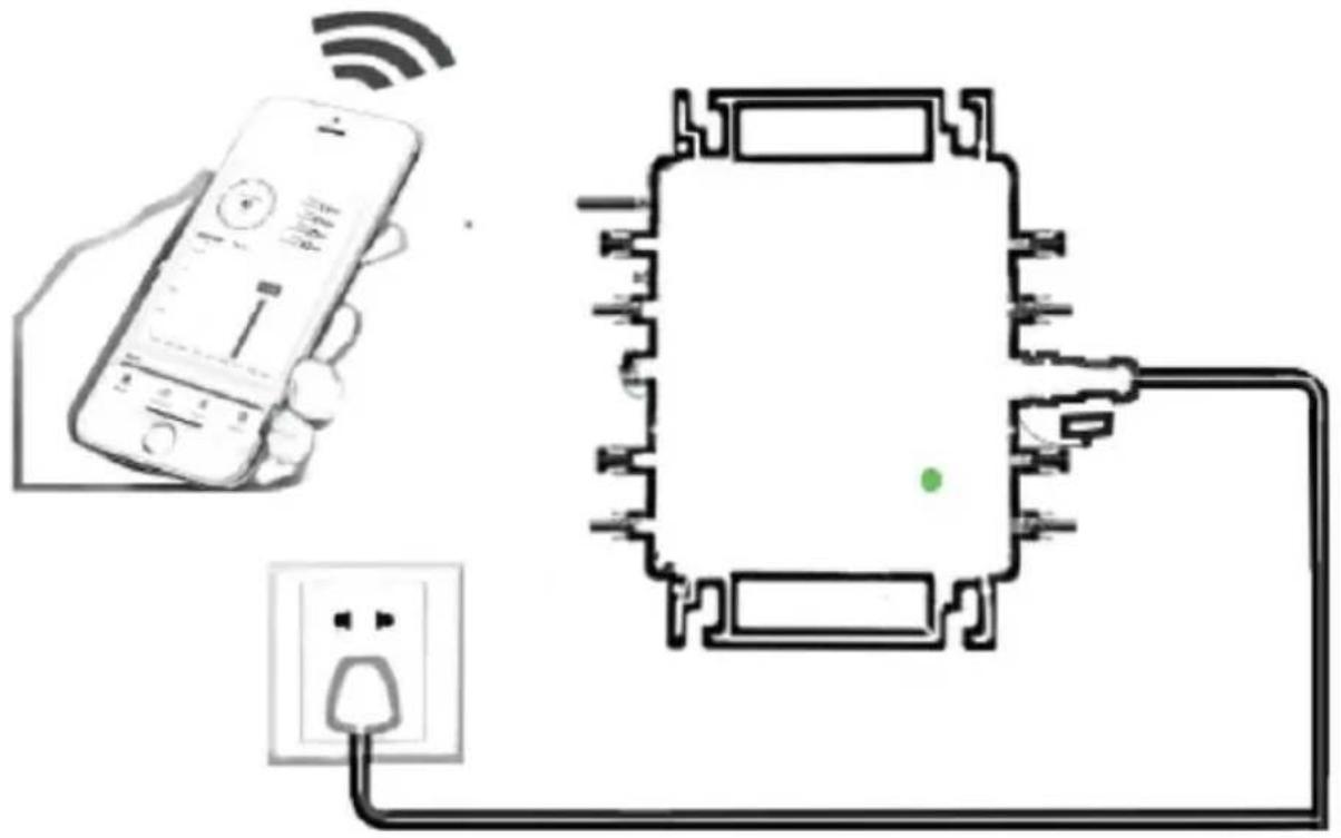
When the inverter is purchased for the first time and connected to the mobile phone for monitoring, it is only necessary to switch on the mains AC. The blue light beside it flashes, and the inverter can be connected through WIFI or Bluetooth pairing. When the inverter can be controlled through the mobile phone, it is indicated that the connection is normal.
- WHAT TO DO when the Smart-App can't find the micro inverter to be added?
Check the following points:
- Check if the WiFi status indicator of the micro inverter is in the "Blue Flashing" state.
- Check if the Bluetooth function of your smart device is turned on.
- Check if the signal of the wireless network is good.
If all these are the case and the inverter is still not found, press the red button for more than 5 seconds to reset. After the WiFi indicator light flashes blue again, use "Smart Life" App to reconfigure the network.
- WHAT TO DO if I have multiple micro inverters to configure?
Install all micro inverters properly and make them work normally to generate power, and then operate according to the configuration and steps. The App can search all inverters to be added at one time and configure them at one time.
- WHAT TO DO if the SSID of my WiFi network or the password is changed
Please reconfigure the inverter according to the configuration and usage steps.
- WHAT TO DO if the WiFi status indicator of the inverter goes out, but the device displayed on the app is not online?
This means that you can connect to the wireless network device, but can't connect to the cloud server. It means that your wireless network device can't connect to the Internet. Make sure that your Internet is properly connected.
- The installation site of the inverter is temporarily not equipped with a router and no WiFi signal?
- How does App connect the inverter and detect if the inverter is working properly?
- You can use an idle smartphone to open the WiFi sharing of mobile phone signal hotspot for connection, and reconfigure the network connection after installing the router.
- There are multiple WiFi signals around. Can we connect different WiFi signals?
No, the WiFi connected of the micro inverter and the smart phone must be consistent before the network can be configured.
- Can App configure the micro inverter in different places? Can I view data in different places?
You can't configure the micro inverter in different places, but you can view data in different places. The inverter uploads the latest status data to the cloud server every 3-5 minutes.
- After checking that there is no problem, the App still cannot find the micro inverter.
- Press and hold the inverter red button for more than 5 seconds to reset the inverter.
- After the WiFi indicator flashes again, use App to reconfigure the network.
- WHAT TO DO if I want to monitor the same inverter on two or more smart devices?
You can share the inverter with another phone using the share device feature.
- Will App data be saved?
Yes, App data will be stored on the cloud server. After the network is successfully configured, you can view the data at any time and place.
- The inverter cannot be connected to the app at night?
At night, because the solar panel does not generate power, the microinverter does not have any power input, so it will go offline and it is in
to re-configure the network at night.
ACCESSORIES LIST
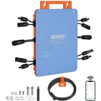
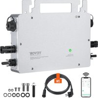
- Operating instructions *1 2. Grid connected power cord *1 3. 8mm diameter, 28mm long hex socket screw + flat washer + spring washer + nut *2 4. 5mm diameter, 13mm long hex socket screw + nut *2 (600W/800W) 4mm diameter, 8mm long hex socket screw *1 (1200W) 5. WiFi antenna *1
Manufacturer: Shanghaimuxinmuyeyouxiangongsi
Address: Shuangchenglu 803nong11hao1602A-1609shi, baoshanqu, shanghai 200000 CN.
Imported to AUS: SIHAO PTY LTD, 1 ROKEVA STREETEASTWOOD NSW 2122 Australia
Imported to USA: Sanven Technology Ltd., Suite 250, 9166 Anaheim Rancho Cucamonga, CA 91730
E-CrossStu GmbH
Mainzer Landstr. 69, 60329 Frankfurt am Main
YH CONSULTING LIMITED.
C/O YH Consulting Limited Office 147, Centurion House, London Road, Staines-upon-Thames, Surrey, TW18 4AX
VEVOR®
TOUGH TOOLS, HALF PRICE
Technical Support and E-Warranty Certificate
www.vevor.com/support
VEVOR®
We continue to be committed to providing you with tools at competitive prices. "Save Half", "Half Price", or any other similar expressions used by us only represent an estimate of savings you might benefit from buying certain tools with us compared to top brands, and does not necessarily mean to cover all categories of tools offered. We kindly remind you to verify carefully when placing an order with us that you are actually saving half in comparison with the top major brands.
MODEL: GT-600/GT-800/GT-1200
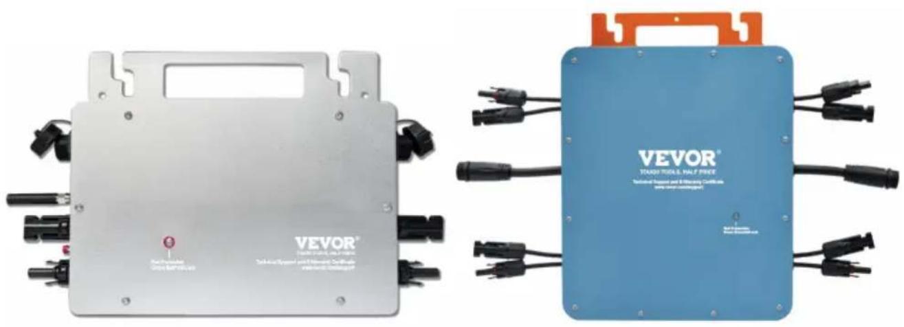
GT-600/GT-800 GT-1200
Have product questions? Need technical support? Please feel free to contact us:
Technical Support and E-Warranty Certificate
www.vevor.com/support
This is the original instruction. Please read all manual instructions carefully before operating. VEVOR reserves a clear interpretation of the user manual. The appearance of the product shall be subject to the product you received. Please forgive us that we won't inform you of any technology or software updates on our product.
1 2



1
Download the mobile application: SmartLife or scan the QR code directly.
2
Register a personal account.
3
Restore factory settings: Press and hold the red key for 5-10 seconds and release it. The blue light is flashing and the instrument is connected successfully.
4
Add inverter.
5
Further add confirmation information.
6
Make sure the Bluetooth or Wi-Fi on the phone is on.
7
Enter your home Wi-Fi account information and password.
8
Click Next to install, and modify the name and account freely.
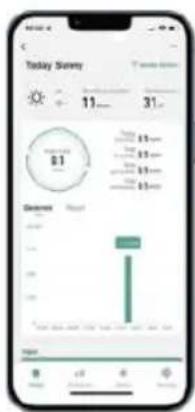
9
The interface can control the system switch normally. The connection is successful.
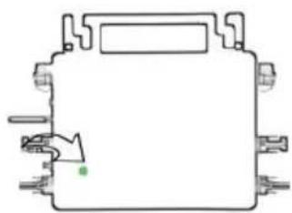
10
10. The connection is successful, and the green light of the inverter is always on in normal operation. Occasionally flashing indicates that the MPPT is tracking the optimal voltage.
INSTRUCTIONS FOR INSTALLATION AND WIRING
GT-600/800, GT-1200
Normal working conditions of the inverter: the 22-50V DC voltage of the solar panel must be connected, and the AC voltage must be connected at the same time, and the indicator light is green. Only the solar panel is connected. When the mains AC is not connected, the red light on the inverter surface is on, and the instrument and machine do not work normally.

GT-600/800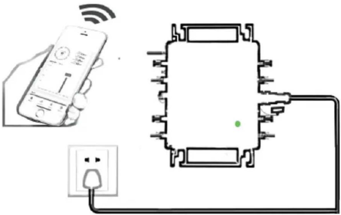
![graph TD A["Power Source"] --> B["Central Device"] C["Solar Panel 1"] --> B D["Solar Panel 2"] --> B E["Solar Panel 3"] --> B F["Solar Panel 4"] --> B B --> G["Output"] style B fill:#f9f,stroke:#333,stroke-width:2px note right of B: ✓ yes](/content/2026/04/735589/images/475c1be47ed72d064a86b187675496ed55ed411e3510705a814e32366e78b2be.jpg)
Normal working conditions of the inverter: the 22-50V DC voltage of the solar panel must be connected, and the AC voltage must be connected at the same time, and the indicator light is green. Only the solar panel is connected. When the mains AC is not connected, the red light on the inverter surface is on, and the instrument and machine do not work normally.
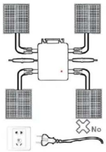
GT-1200
Note:
C/O YH Consulting Limited Office 147, Centurion House, London Road, Staines-upon-Thames, Surrey, TW18 4
VEVOR®
TOUGH TOOLS, HALF PRICE
We continue to be committed to provide you tools with competitive price. "Save Half", "Half Price" or any other similar expressions used by us only represent estimate of savings you might benefit from buying certain tools with us compared to top brands and does not necessarily mean to cover all categories of tools offered. We kindly remind you to verify carefully when you are placing an order with us that you are actually saving half in comparison with the top major brands.
MODEL: GT-600/GT-800/GT-1200
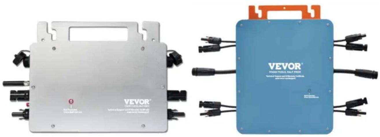
GT-600/GT-800 GT-1200
Have product questions? Need technical support? Please feel free to contact us:
Technical Support and E-Warranty Certificate
www.vevor.com/support
This is the original instruction. Please read all manual instructions carefully before operating. VEVOR reserves the right to interpret the user manual. The appearance of the product shall be subject to the product you received. Please forgive us that we won't inform you if there are any technology or software updates on our product.
WARNING: RISK OF ELECTRIC SHOCK
1 2
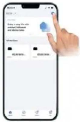
1
Download the mobile application: SmartLife or scan the QR code directly
2
Register personal account
3
Restore factory settings: Press and hold the red key for 5-10 seconds, then release it. The blue light will flash, indicating that the instrument has been connected successfully.
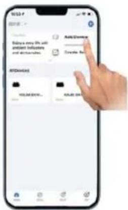
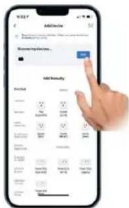
4
Add inverter
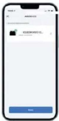
5
Further add confirmation information
6
Make sure the Bluetooth or Wi-Fi on the phone is turned on.
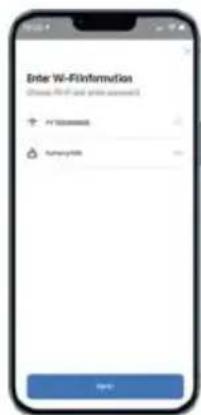
7
Enter your home Wi-Fi account information and password.
8
Click Next to install, and modify the name and account freely.
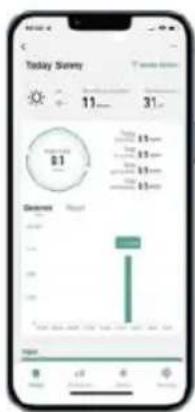
9
The interface can control the system switch normally. The connection is successful.
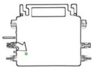
10
10 The connection is successful, and the green light of the inverter is always on in normal operation. Occasionally flashing instrument MPPT is tracking the optimal voltage
Remove device
INSTRUCTIONS FOR INSTALLATION WIRING
GT-600/800 GT-1200
GT-600/800 GT-1200
Normal working conditions of the inverter: the 22-50V DC voltage of the solar panel must be connected, and the AC voltage must be connected at the same time, and the indicator light is green
Only the solar panel is connected. When the mains AC is not connected, the red light on the inverter surface is on, and the instrument and machine do not work normally
GT-600/800
![graph TD A["Power Source"] --> B["Central Device"] C["Solar Panel 1"] --> B D["Solar Panel 2"] --> B E["Solar Panel 3"] --> B F["Solar Panel 4"] --> B G["Yes"] --> H["Checkmark"] style B fill:#f9f,stroke:#333](/content/2026/04/735589/images/4b4d73b87309ab30a6242fb87a74e3feca11e6cfb5a3a0adabb6e1fc8627ecf6.jpg)
Normal working conditions of the inverter: the 22-50V DC voltage of the solar panel must be connected, and the AC voltage must be connected at the same time, and the indicator light is green
Only the solar panel is connected. When the mains AC is not connected, the red light on the inverter surface is on, and the instrument and machine do not work normally
GT-1200
Note:
C/O YH Consulting Limited Office 147, Centurion H, London Road, Staines-upon-Thames, Surrey, TW18 4
VEVOR®
TOUGH TOOLS, HALF PRICE
www.vevor.com/support
VEVOR®
We continue to be committed to providing you with tools at competitive prices. "Save Half", "Half Price", or any other similar expressions used by us only represent an estimate of savings you might benefit from buying certain tools with us compared to top brands, and does not necessarily mean to cover all categories of tools offered. We kindly remind you to verify carefully when placing an order with us whether you are actually saving half in comparison with the top major brands.
MODEL: GT-600/GT-800/GT-1200
MODELS GT-600/GT-800/GT-1200
Have product questions? Need technical support? Please feel free to contact us:
Technical Support and E-Warranty Certificate
www.vevor.com/support
This is the original instruction. Please read all manual instructions carefully before operating. VEVOR reserves the right to interpret the user manual. The appearance of the product shall be subject to the product you received. Please forgive us that we won't inform you of any technology or software updates on our product.
1 2



1
Download the mobile application: SmartLife or scan the QR code directly
2
Register personal account
3
Restore factory settings: Press and hold the red key for 5-10 seconds and release it. The blue light is flashing and the instrument is connected successfully.
4
Add inverter
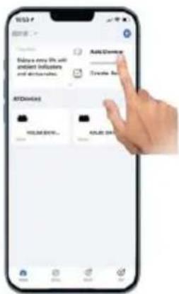

5
Further add confirmation information
6
Make sure the Bluetooth or Wi-Fi in the phone is on
7
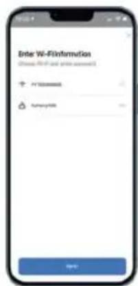
Enter your home Wi-Fi account information and password
8
Click Next to install and modify the name and account freely
9
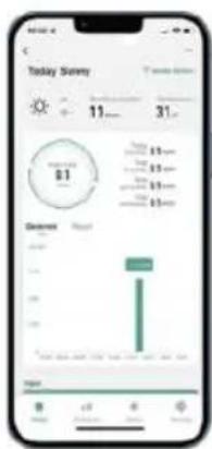
The interface can control the system switch normally. The connection is successful.
10 The connection is successful, and the green light of the inverter is always on in normal operation. Occasionally flashing instrument MPPT is tracking the optimal voltage
Remove device
INSTRUCTIONS FOR INSTALLATION WIRING
Model GT-600/800 The GT-1200
Models GT-600/800/1200
Normal working conditions of the inverter: the 22-50V DC voltage of the solar panel must be connected, and the AC voltage must be connected at the same time, and the indicator light is green
Only the solar panel is connected. When the mains AC is not connected, the red light on the inverter surface is on, and the instrument and machine do not work normally
GT-600/800
![graph TD A["Power Source"] --> B["Central Device"] C["Solar Panel 1"] --> B D["Solar Panel 2"] --> B E["Solar Panel 3"] --> B F["Solar Panel 4"] --> B G["Yes"] --> H["Checkmark"] style B fill:#f9f,stroke:#333](/content/2026/04/735589/images/77320f37c528251a1fe499e2c72ebee6ec369cfce8e8b52b7d1eb47056b78523.jpg)
Normal working conditions of the inverter: the 22-50V DC voltage of the solar panel must be connected, and the AC voltage must be connected at the same time, and the indicator light is green
Only the solar panel is connected. When the mains AC is not connected, the red light on the inverter surface is on, and the instrument and machine do not work normally
The GT-1200
Note:
Imported in AUS: SIHAO PTY LTD, 1 ROKEVA STREETEASTWOOD NSW 2122 Australia
Imported in the USA: Sanven Technology Ltd., Suite 250, 9166 Anahei Place, Rancho Cucamonga, CA 91730
E-CrossStu GmbH
Mainzer Landstr.69, 60329 Frankfurt am Main
YH CONSULTING LIMITED.
C/O YH Consulting Limited Office 147, Centurion House, London Road, Staines-upon-Thames, Surrey, TW18 4
VEVOR®
TOUGH TOOLS, HALF PRICE
www.vevor.com/support
VEVOR®
We continue to be committed to provide you tools with competitive price. "Save Half", "Half Price" or any other similar expressions used by us only represent estimate of savings you might benefit from buying certain tools with us compared to top brands and does not necessarily mean to cover all categories of tools offered. We kindly remind you to verify carefully when you are placing an order with us that you are actually saving half in comparison with the top major brands.
MODEL: GT-600/GT-800/GT-1200
GT-600/GT-800 GT-1200
Have product questions? Need technical support? Please feel free to contact us:
Technical Support and E-Warranty Certificate
www.vevor.com/support
This is the original instruction, please read all manual instructions carefully before operating. VEVOR reserves a clear interpretation of the user manual. The appearance of the product shall be subject to the product you received. Please forgive us that we won't inform you of any technology or software updates on our product.
1 2
1
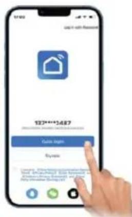
Download the mobile application: SmartLife or scan the QR code directly.
2
Register a personal account.
3
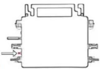
Restore factory settings: Press and hold the red key for 5-10 seconds and release it. The blue light is flashing and the instrument is connected successfully.
4
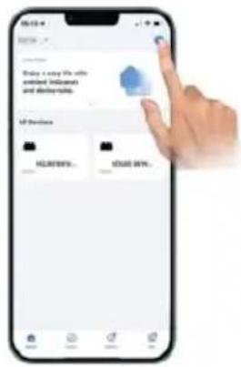
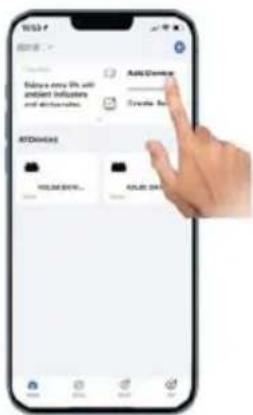
Add inverter.

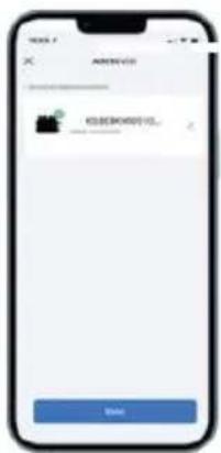
5
Further add confirmation information.
6
Make sure the Bluetooth or Wi-Fi on the phone is on.
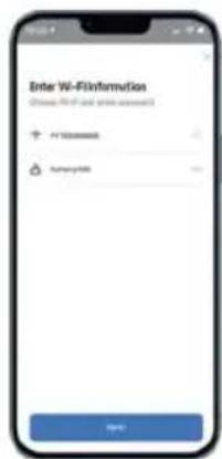
7
Enter your home WiFi account information and password.
8
Click Next to install and modify the name and account freely.
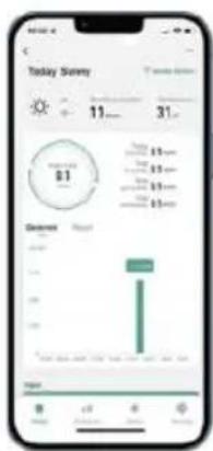
9
The interface can control the system switch normally. The connection is successful.
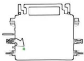
10
10 The connection is successful, and the green light of the inverter is always on in normal operation. Occasionally flashing instrument MPPT is tracking the optimal voltage.
Remove device
INSTRUCTIONS FOR INSTALLATION WIRING
GT-600/800 GT-1200
GT-600/800 GT-1200
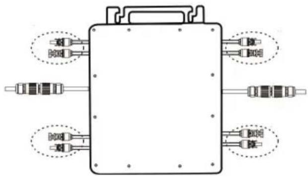
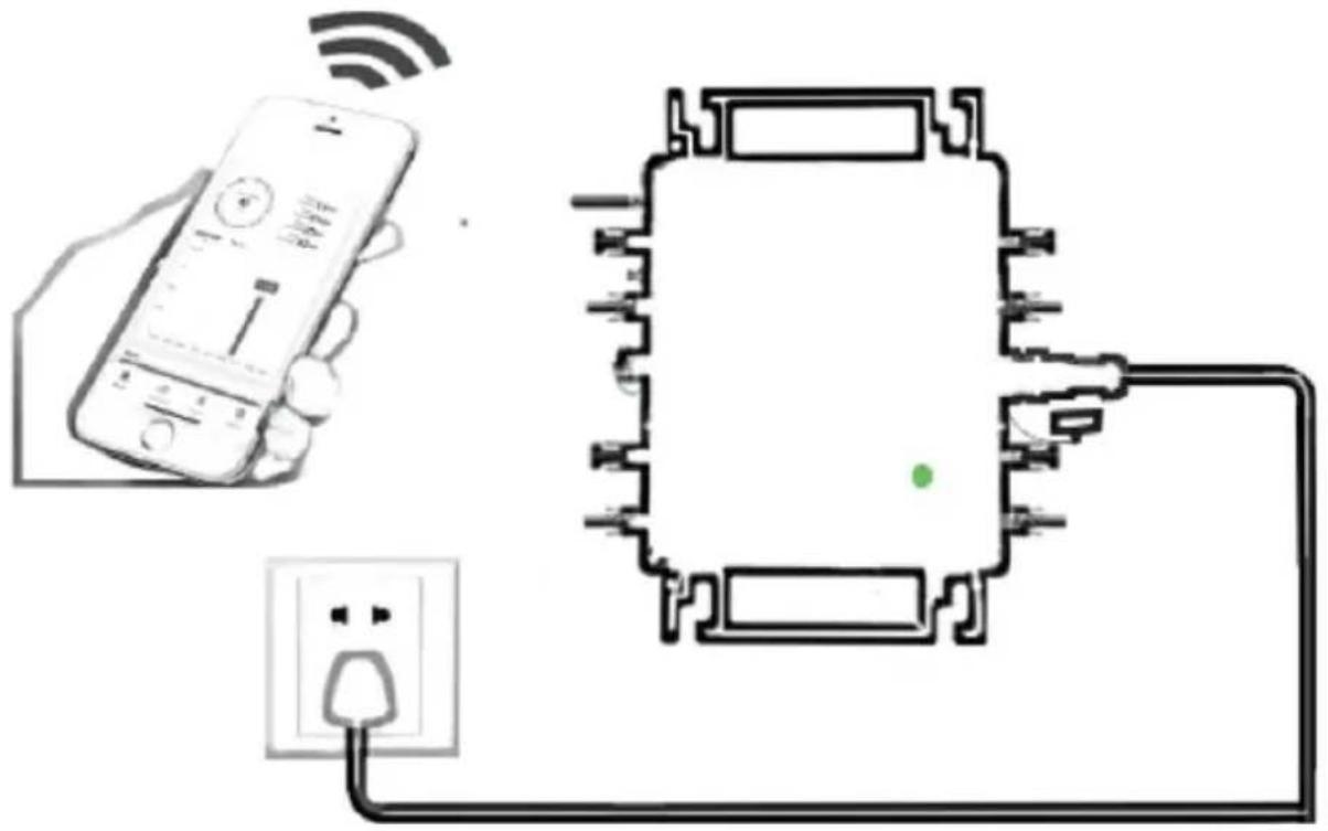
Normal working conditions of the inverter: the 22-50V DC voltage of the solar panel must be connected, and the AC voltage must be connected at the same time, and the indicator light is green.
Only the solar panel is connected. When the mains AC is not connected, the red light on the inverter surface is on, and the instrument and machine do not work normally.
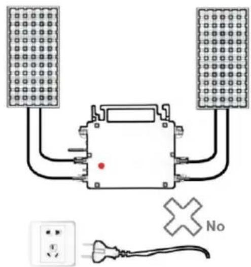
GT-600/800
![graph TD A["Power Source"] --> B["Central Device"] C["Solar Panel 1"] --> B D["Solar Panel 2"] --> B E["Solar Panel 3"] --> B F["Solar Panel 4"] --> B G["Yes"] --> H["Checkmark"] style B fill:#f9f,stroke:#333](/content/2026/04/735589/images/cd0d1b9e5bda15d76ce7a913cc1a95ee8806873996ef1216b7fc5ffa14dceb97.jpg)
Normal working conditions of the inverter: the 22-50V DC voltage of the solar panel must be connected, and the AC voltage must be connected at the same time, and the indicator light is green.
Only the solar panel is connected. When the mains AC is not connected, the red light on the inverter surface is on, and the instrument and machine do not work normally.
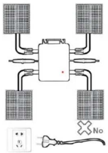
GT-1200
Note:
Imported to AUS: SIHAO PTY LTD, 1 ROKEVA STREETEASTWOOD NSW 2122 Australia
Imported to USA: Sanven Technology Ltd., Suite 250, 9166 Anah Place, Rancho Cucamonga, CA 91730
E-CrossStu GmbH
Mainzer Landstr.69, 60329 Frankfurt am Main
YH CONSULTING LIMITED.
C/O YH Consulting Limited Office 147, Centurion House, London Road, Staines-upon-Thames, Surrey, TW18 4
VEVOR®
TOUGH TOOLS, HALF PRICE
We continue to be committed to provide you tools with competitive price. "Save Half", "Half Price" or any other similar expressions used by us only represent estimate of savings you might benefit from buying certain tools with us compared to top brands and does not necessarily mean to cover all categories of tools offered. We are kindly reminded to verify carefully when you are placing an order with us actually saving half in comparison with the top major brands.
MODEL: GT-600/GT-800/GT-1200

USER NAME: GT-600/GT-800
Have product questions? Need technical support? Please feel free to contact us:
Technical Support and E-Warranty Certificate
www.vevor.com/support
This is the original instruction. Please read all manual instructions carefully before operating. VEVOR reserves a clear interpretation of the user manual. The appearance of the product shall be subject to the product you received. Please forgive us that we won't inform you if there are any technology or software updates on our product.
1 2
1
Download the mobile application: SmartLife or scan the QR code directly.
2
Register a personal account.
3
Restore factory settings: Press and hold the red key for 5-10 seconds and release it. The blue light is flashing and the instrument is connected successfully.
4
Add inverter.
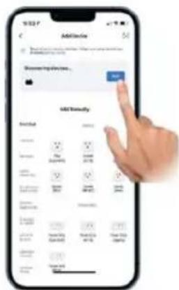
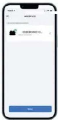
5
Further add confirmation information.
6
Make sure the Bluetooth or Wi-Fi in the phone is on.
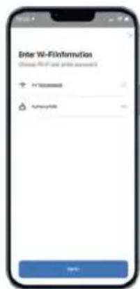
7
Enter your home Wi-Fi account information and password.
8
Click Next to install and modify the name and account freely.
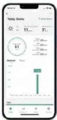
9
The interface can control the system switch normally. The connection is successful.
10
10. The connection is successful, and the green light of the inverter is always on in normal operation. Occasionally flashing instrument MPPT is tracking the optimal voltage.
Remove device
INSTRUCTIONS FOR INSTALLATION WIRING
Normal working conditions of the inverter: the 22-50V DC voltage of the solar panel must be connected, and the AC voltage must be connected at the same time, and the indicator light is green. Only the solar panel is connected. When the mains AC is not connected, the red light on the inverter surface is on, and the instrument and machine do not work normally.
GT-600/800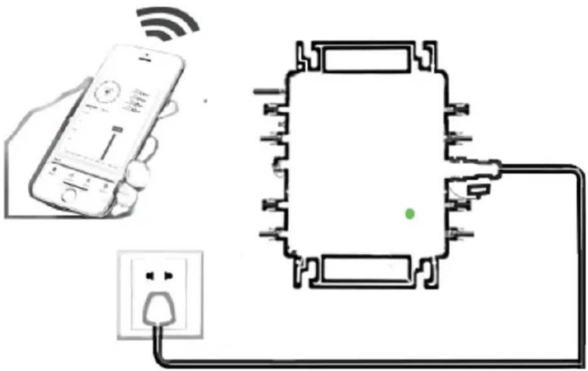
![graph TD A["Power"] --> B["Central Device"] C["Solar Panel 1"] --> B D["Solar Panel 2"] --> B E["Solar Panel 3"] --> B F["Solar Panel 4"] --> B G["Yes"] --> H["Checkmark"] style H fill:#fff,stroke:#000,stroke-width:2px](/content/2026/04/735589/images/36fb390f16036630a63f9390679a9bd539f390c07381c7376de31505b323ebf8.jpg)
Normal working conditions of the inverter: the 22-50V DC voltage of the solar panel must be connected, and the AC voltage must be connected at the same time, and the indicator light is green. Only the solar panel is connected. When the mains AC is not connected, the red light on the inverter surface is on, and the instrument and machine do not work normally.
GT-1200
Note:
Imported into AUS: SIHAO PTY LTD, 1 ROKEVA STREETEASTWO NSW 2122 Australia
Imported into USA: Sanven Technology Ltd., Suite 250, 9166 Anaheim Place, Rancho Cucamonga, CA 91730
E-CrossStu GmbH
Mainzer Landstr.69, 60329 Frankfurt am Main
YH CONSULTING LIMITED.
C/O YH Consulting Limited Office 147, Centurion H, London Road, Staines-upon-Thames, Surrey, TW18 4
VEVOR®
TOUGH TOOLS, HALF PRICE
www.vevor.com/support
VEVOR®
Technical Support and E-warranty Certificate
www.vevor.com/support
MICRO-INVERTER
MODEL: GT-600/GT-800/GT-1200
We continue to be committed to provide you with tools at competitive prices. "Save Half", "Half Price" or any other similar expressions used by us only represent an estimate of savings you might benefit from buying certain tools with us compared to top brands, and does not necessarily mean to cover all categories of tools offered. We kindly remind you to verify carefully when placing an order with us that you are actually saving half in comparison with the top major brands.
MODEL: GT-600/GT-800/GT-1200
GT-600/GT-800 GT-1200
Have product questions? Need technical support? Please feel free to contact us:
Technical Support and E-Warranty Certificate
www.vevor.com/support
This is the original instruction. Please read all manual instructions carefully before operating. VEVOR reserves the right to interpret the user manual. The appearance of the product shall be subject to the product you received. Please forgive us that we won't inform you of any technology or software updates on our product.
WARNING: RISK OF ELECTRIC SHOCK
1 2



1
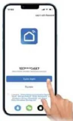
Download the mobile application: Smart Life or scan the QR code directly.
2
Register a personal account.
3
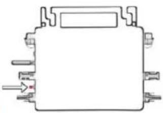
Restore factory settings: Press and hold the red key for 5-10 seconds and release it. The blue light is flashing and the instrument is connected successfully.
4
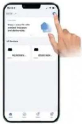
Add inverter
5
Further add confirmation information
6
Make sure the Bluetooth or Wi-Fi on the phone is on
7
Enter your home Wi-Fi account information and password
8
Click Next to install and modify the name and account freely
9
The interface can control the system switch normally. The connection is successful
10
10. The connection is successful, and the green light of the inverter is always on in normal operation. Occasionally flashing means the MPPT is tracking the optimal voltage
INSTRUCTIONS FOR INSTALLATION AND WIRING
GT-600/800 GT-1200
GT-600/800 GT-1200
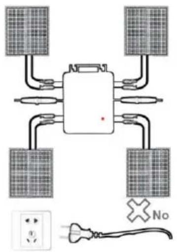
Normal working conditions of the inverter: the 22-50V DC voltage of the solar panel must be connected, and the AC voltage must be connected at the same time, and the indicator light is green.
Only the solar panel is connected. When the mains AC is not connected, the red light on the inverter surface is on, and the instrument and machine do not work normally.
GT-600/800
![graph TD A["Power Source"] --> B["Central Device"] C["Solar Panel 1"] --> B D["Solar Panel 2"] --> B E["Solar Panel 3"] --> B F["Solar Panel 4"] --> B G["Yes"] --> H["Checkmark"] style H fill:#fff,stroke:#000,stroke-width:2px](/content/2026/04/735589/images/c3d60e2a48311fa596835be64707da571ec32e6e336dc0dd2cb676280ec3ee09.jpg)
Normal working conditions of the inverter: the 22-50V DC voltage of the solar panel must be connected, and the AC voltage must be connected at the same time, and the indicator light is green.
Only the solar panel is connected. When the mains AC is not connected, the red light on the inverter surface is on, and the instrument and machine do not work normally.
GT-1200
Note:
C/O YH Consulting Limited Office 147, Centurion H, London Road, Staines-upon-Thames, Surrey, TW18 4
VEVOR®
TOUGH TOOLS, HALF PRICE
www.vevor.com/support
VEVOR®
We continue to be committed to providing you with tools at competitive prices. "Save Half", "Half Price" or any other similar expressions used by us only represent an estimate of savings you might benefit from buying certain tools with us compared to top brands, and does not necessarily mean to cover all categories of tools offered. We kindly remind you to verify carefully when placing an order with us to ensure you are actually saving half in comparison with the top major brands.
MODEL: GT-600/GT-800/GT-1200
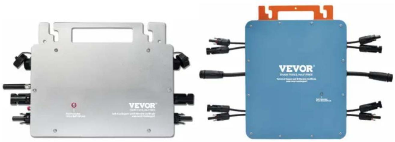
GT-600/GT-800 GT-1200
Have product questions? Need technical support? Please feel free to contact us:
Technical Support and E-Warranty Certificate
www.vevor.com/support
This is the original instruction. Please read all manual instructions carefully before operating. VEVOR reserves a clear interpretation of the user manual. The appearance of the product shall be subject to the product you received. Please forgive us that we won't inform you of any technology or software updates on our product.
1 2
- @Enfas 110 V network Max 2 units or @Enfas 230V network




1
Download the mobile application: Smart Life or scan the QR code directly
2
Register a personal account
3
Restore factory settings: Press and hold the red key for 5-10 seconds and release it. The blue light is flashing and the instrument is connected successfully
4
Add inverter
5
Further add confirmation information
6
Make sure the Bluetooth or wifi in the phone is on
7
Enter your home WIFI account information password
8
Click Next to install and modify the name and account freely
9
The interface can control the system switch normally. The connection is successful
10
10 The connection is successful, and the green light of the inverter is always on in normal operation. Occasionally flashing instrument MPPT is tracking the optimal voltage
Remove device
GT-600/800 GT-1200
GT-600/800 GT-1200
GT-600/800 GT-1200
Normal working conditions of the inverter: the 22-50V DC voltage of the solar panel must be connected, and the AC voltage must be connected at the same time, and the indicator light is green. Only the solar panel is connected. When the mains AC is not connected, the red light on the inverter surface is on, and the instrument and machine do not work normally.
GT-600/800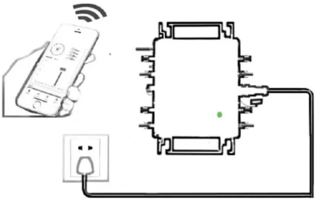
![graph TD A["Power"] --> B["Central Device"] C["Solar Panel 1"] --> B D["Solar Panel 2"] --> B E["Solar Panel 3"] --> B F["Solar Panel 4"] --> B G["Yes"] --> H["Checkmark"] style H fill:#fff,stroke:#000,stroke-width:2px](/content/2026/04/735589/images/77c1e7e517f2ef558a2e8e6ebda2cb6bcaf6c67ebbe2a8a508c88232df67729a.jpg)
Normal working conditions of the inverter: the 22-50V DC voltage of the solar panel must be connected, and the AC voltage must be connected at the same time, and the indicator light is green. Only the solar panel is connected. When the mains AC is not connected, the red light on the inverter surface is on, and the instrument and machine do not work normally.
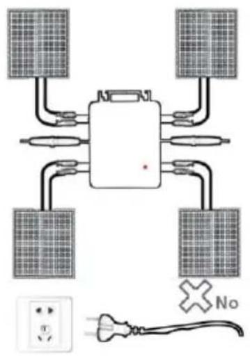
GT-1200
Note:
C/O YH Consulting Limited Office 147, Centurion H, London Road, Staines-upon-Thames, Surrey, TW18 4
VEVOR®
TOUGH TOOLS, HALF PRICE
www.vevor.com/support