USER MANUAL AT1-4000X Vevor
Technical Support and E-Warranty Certificate www.vevor.com/support
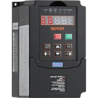
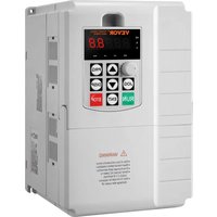
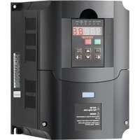
Inverter
MODEL:AT1-4000X
We continue to be committed to provide you tools with competitive price. "Save Half", "Half Price" or any other similar expressions used by us only represer estimate of savings you might benefit from buying certain tools with us compared to top brands and does not necessarily mean to cover all categories of tools offered by are kindly reminded to verify carefully when you are placing an order with us if yo actually saving half in comparison with the top major brands.
MODEL:AT1-4000X
Have product questions? Need technical support? Please feel free contact us:
Technical Support and E-Warranty Certificate
www.vevor.com/support
This is the original instruction, please read all manual instructions carefully before operating. VEVOR reserves a clear interpretation of user manual. The appearance of the product shall be subject to the product you received. Please forgive us that we won't inform you there are any technology or software updates on our product.
IMPORTANT SAFEGUARDS

natural_image
Blue circular icon with a white silhouette of a person reading a book (no text or symbols)
Read all safety warnings, instructions, illustrations and specifications provided with this inverter. Failure to follow all instructions listed below may result in electric shock, fire and/or serious injury.
WARNING :
This equipment is a high voltage device, please do not attempt to disassemble this equipment at any time to avoid danger. After a device failure, if the external switch fails to restart the device, please contact yo reseller for handling.
WARNING: ELECTRICAL SHOCK AND FIRE HAZARD!
- Failure to comply with this instruction could result in an electrical failure and electrocution.
- DO NOT DISASSEMBLE .
- Do not submerge inverter.
- Do not connect two or more transformers in parallel
- Plug the power supply unit directly into a GFCI wet location outlet.
- Do not use an extension cord
- Installation of this inverter and related wiring must be done by a qualified electrician in compliance with all applicable electrical codes.
WARNING :
Changes or modifications to this unit not expressly approved by the party responsible for compliance could void the users authority to operate the equipment.
SAVE THESE INSTRUCTIONS
CAUTION: Changes or modifications not expressly approved by the party responsible for compliance could void the user's authority to operate the equipment!
This device complies with Part 15 of the FCC Rules. Operation is subject to the following two conditions:
1) This product may cause harmful interference.
2) This product must accept any interference received, including interference that may cause undesired operation.
WARNING: Changes or modifications to this product not expressly approved by the party.responsible for compliance could void the user's authority to operate the product.
Note: This product has been tested and found to comply with the limits a Class B digital device pursuant to Part 15 of the FCC Rules, These li are designed to provide reasonable protection against harmful interference in a residential installation.
This product generates, uses and can radiate radio frequency energy, and if not installed and used in accordance with the instructions, may cause harmful interference to radio communications. However, there is no guarantee that interference will not occur in a particular installation. If this product does cause harmful interference to radio or television reception, which can be determined by turning the product off and on, the user is encouraged to try to correct the interference by one or more of the following measures.
- Reorient or relocate the receiving antenna.
- Increase the distance between the product and receiver.
- Connect the product to an outlet on a circuit different from that to which the receiver is connected.
- Consult the dealer or an experienced radio/TV technician for assistance.
Correct Disposal
This product is subject to the provision of European Directive 2012/19/EC. The symbol showing a wheelie bin crossed through indicates that the product requires separate refuse collection in the European Union. This applies to the product and all accessories marked with this symbol. Products marked as such may not be discarded with normal domestic waste, but must be taken to collection point for recycling electrical and electronic devices.
1. Installation and wiring
- Main circuit terminal and function description (1)Single-phase to three-phase
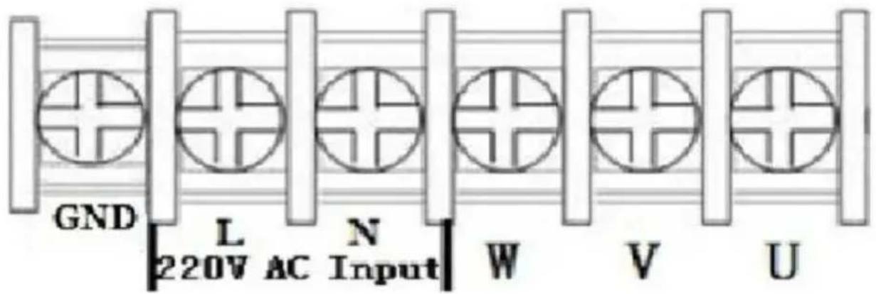
| Terminal label | Function description |
| L,N | Single phase AC 220V input terminal |
| U,V,W | Output terminal connect to Three phase 220V AC motor |
| GND | Grounding terminal |
- Terminal description
| Port | Functional description | Instructions |
| 15V | 15V power output | 200mA15V output |
| X6 | Input port6 (Reversing switch) | Short Port X6 and COM, input sign effective |
| X5 | Input port 5(Reverse rotation Control switch) | Short Port X5 and COM, input sign effective |
| X4 | Input port 4(Forward rotation Control switch) | Short Port X4 and COM, input sign effective |
| X3 | Input port 3(section-speed 3) | Short Port X3 and COM, input sign effective |
| X2 | Input port 2(section-speed 2) | Short Port X2 and COM, input sign effective |
| X1 | Input port 1(section-speed 1) | Short Port X1 and COM, input sign effective |
| 485+/485- | 485 communication po | Optional, only for special model |
| COM | Common GND | |
| VL1 | External analog voltage input | 0-5/10 V Analog voltage input |
| CI | External current sign input | 4-20mA Current input |
| SP1 | Open-collector output | |
| 5V | 5V power output | supply 5V 20mA power output |
| TC | Relay output C | 250VAC 5A/30VDC 3A TA and TB Normal Close ,TA and Normal Open |
| TB | Relay output B |
| TA | Relay output A |
- Multi-speed input Frequency control table :
| Section speed input 1 | Section speed input 2 | Section speed input 3 | Original Frequency |
| Main Speed | 1 | 1 | 1 | 50 |
| Section speed 1 | 0 | 1 | 1 | 45 |
| Section speed 2 | 1 | 0 | 1 | 40 |
| Section speed 3 | 0 | 0 | 1 | 35 |
| Section speed 4 | 1 | 1 | 0 | 30 |
| Section speed 5 | 0 | 1 | 0 | 25 |
| Section speed 6 | 1 | 0 | 0 | 20 |
| Section speed 7 | 0 | 0 | 0 | 15 |
| Note : | 0 means input Port connect with COM, 1 means disconnect. |
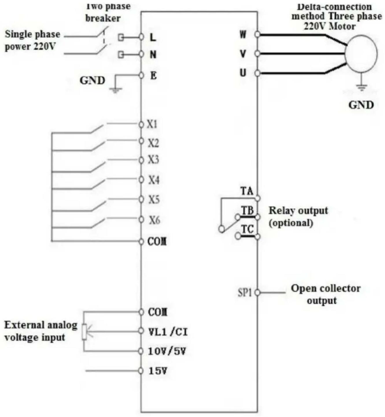
4. Basic operation wiring diagram
(Three phase 220V, if 380V Star-connection method needs to change to the 220V Delta-connection method)
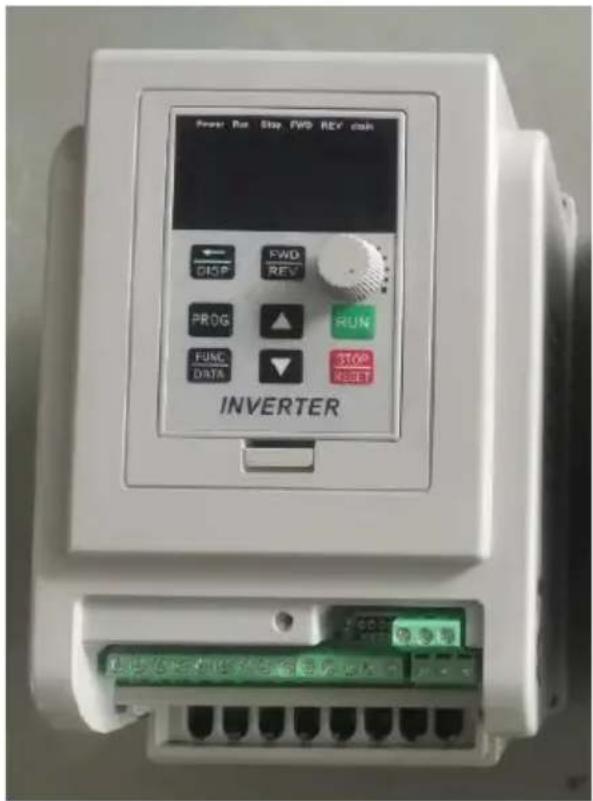
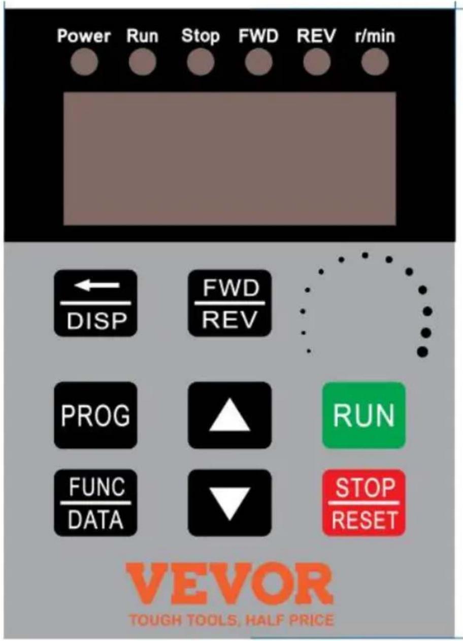
5. Operation panel
| Icon | Function description |
| 1 | (Programming) | For selecting mode or Programming mode (it is available not mater the Inverter star or stop), press this key for modifying parameters. |
| 2 | (Function/ Save) | Function data setting key. Normal mode: press key to display the information of the Inverter, su as target frequency, output frequency and current, temperature; |
| 3 | Key(▲) | Parameter number or parameter value increase | Short press this key, then the numerical value will change gradually. Long press this key, then the numerical value will change rapidly |
| 4 | Key(▼) | Parameter number or parameter value decrease |
| 5 | Shift | Shift in programming mode, jog in normal mode |
| 6 | Forward/ Reverse | Forward/ Reverse switching key |
| 7 | Start | Start Inverter output |
| 8 | Stop / Reset | Break down,fault resetting |
| Note | Please modify the parameters under the stop state, otherwise the changed parameters cannot be saved. |
7. Parameter specification
1. Parameter specification
| Parameter | Parameter specification | Parameter range | Default | Unit |
| P00 | Maximum voltage | 0---220.0/380.0 | 220/380 | V |
| P01 | Reference frequency | 0---400.0 | 50 | Hz |
| P02 | Intermediate voltage | 0---220.0/380.0 | 110/190 | V |
| P03 | Intermediate frequency | 0---400.0 | 25 | Hz |
| P04 | Minimum voltage | 0---220.0/380.0 | 0 | V |
| P05 | Minimum frequency | 0---400.0 | 0 | Hz |
| P06 | Maximum operating | 0---400.0 | 65.0 | Hz |
| P07 | Minimum operating | 0---400.0 | 0 | Hz |
| P08 | Hide password | 0---65535 | 00000 | |
| P09 | Input password | 0---65535 | 0 | |
| P10 | Working frequency source | 0: Panel keyboard;1: Panel potentiometer;2: External analog signal4: RS485. | 1 | |
| P11 | Start/stop control source | 0:Panel keyboard;1:RS485;2:External port. | 0 | |
| P12 | Stopping Modes | 0:Inertial stop;1:Deceleration stop;2: Brake stop;3:Emergency brake. | 1 | |
| P13 | Braking time | 0---2.5 | 0.5 | S |
| P14 | Braked Voltage | 0---140.0 | 20 | V |
| P17 | Machine number | 1-255 | 1 | |
| P18 | Operating arrival | 0---100.0 | 50 | Hz |
| P20 | Over temperature protection selection | 1---80 | 80 | |
| P21 | Revolution for 50Hz | 0-8000 | 2800 | |
| P22 | Carrier setting | 1---20 | 10 | |
| P23 | Frequency adjusting step size | 1---100 | 5 | 0.1Hz |
| P24 | Overload protection buffer time | 0.1---60.0 | 3 | S |
| P26 | Working frequency | 0---400.0 | 50 | Hz |
| P27 | Section speed 1 setting | 0---400.0 | 45 | Hz |
| P28 | Section speed 2 setting | 0---400.0 | 40 | Hz |
| P29 | Section speed 3 setting | 0---400.0 | 35 | Hz |
| P30 | Section speed 4 setting | 0---400.0 | 30 | Hz |
| P31 | Section speed 5 setting | 0---400.0 | 25 | Hz |
| P32 | Section speed 6 setting | 0---400.0 | 20 | Hz |
| P33 | Section speed 7 setting | 0---400.0 | 15 | Hz |
| P34 | Main rising velocity | 1---1000 | 25 | Hz/S |
| P35 | 1st rising velocity | 1---1000 | 25 | Hz/S |
| P36 | 2nd rising velocity | 1---1000 | 25 | Hz/S |
| P37 | 3rd rising velocity | 1---1000 | 25 | Hz/S |
| P38 | 4th rising velocity | 1---1000 | 25 | Hz/S |
| P39 | 5th rising velocity | 1---1000 | 25 | Hz/S |
| P40 | 6th rising velocity | 1---1000 | 25 | Hz/S |
| P41 | 7th rising velocity | 1---1000 | 25 | Hz/S |
| P42 | Main descent velocity | 1---1000 | 25 | Hz/S |
| P43 | 1st descent velocity | 1---1000 | 25 | Hz/S |
| P44 | 2nd descent velocity | 1---1000 | 25 | Hz/S |
| P45 | 3rd descent velocity | 1---1000 | 25 | Hz/S |
| P46 | 4th descent velocity | 1---1000 | 25 | Hz/S |
| P47 | 5th descent velocity | 1---1000 | 25 | Hz/S |
| P48 | 6th descent velocity | 1---1000 | 25 | Hz/S |
| P49 | 7th descent velocity | 1---1000 | 25 | Hz/S |
| P50 | Multi function input 1(X1 binding post) | 0:invalid,terminal is non-functioning | 13 | |
| P51 | Multi function input 2 | 1:wire control stop | 14 | |
| P52 | Multi function input 3 | 2:keying stop; | 15 | |
| P53 | Multi function input 4 | 3:keying operation; | 5 | |
| P54 | Multi function input 5 | 4:stop keying; | 6 | |
| P55 | Multi function input 6 | 5:wire forward operation6: wire reverse operation;7: reservation8: error reset signal;9: wire reversing switch;10:keying forward switching;11:keying forward switching;12: reverse switch keying;13: section speed input 1;14:section speed input 2;15: section speed input 3;16: external error signal.17: Jog Forward;18: Jog Reverse;19: Emergency stop;20:Relay Control. | 9 | |
| P58 | Multi function input 1 (SP1) | 0: invalid, no output;1:operating instructions;2: set arrival instructions3: fault indication;5: Emergency stop;6: For P50---P55=20; | 0 | |
| P60 | Multi function input 2 | Idem (Relay output) | 0 | |
| P62 | Display options | 0: setting frequency;1: operating frequency;2: revolution 3: current;4: temperature; 5: time; | 0 | |
| P65 | Power on options | 0: normal power on 1:report error with start signal;2:Power on forward;3:Power on reverse. | 0 | |
| P66 | Input stabilization time | 0---65535 | 60 | mS |
| P67 | Voltage coefficient | 0---65535 | 28500 | |
| P68 | Under voltage setting | 0---220/380 | 60/180 | V |
| P69 | Over voltage setting | 220.0---400/680 | 400/600 | V |
| P70 | Torque compensation options | 0:P72 is compensation amount;1: Multiply P72 by P71 after P71 minus input voltage | 0 | |
| P71 | Torque compensation voltage | 0---300.0 | 10 | V |
| P72 | Torque compensation setting | 0---100 | 0 | |
| P73 | Maximum external analog | 0---65535 | 31440 | |
| P74 | Minimum external analog | 0---65535 | 2096 | |
| P75 | Zero current compensation value | 0---65535 | 1130 | |
| P76 | Current coefficient | 0---65535 | 42000 | |
| P77 | Parameter reset | 0---65535(It is the reset whe 54321) | 0 | |
| P78 | Main current overload | 0-65535 | 20000 | mA |
| P79 | First current overload | 0-65535 | 20000 | mA |
| P80 | Second current overload | 0-65535 | 20000 | mA |
| P81 | Third current overload | 0-65535 | 20000 | mA |
| P82 | Fourth current overload | 0-65535 | 20000 | mA |
| P83 | Fifth current overload | 0-65535 | 20000 | mA |
| P84 | Sixth current overload | 0-65535 | 20000 | mA |
| P85 | Seventh current overload | 0-65535 | 20000 | mA |
| P86 | Jog forward frequency | 0---400.0 | 20 | Hz |
| P87 | Jog reverse frequency | 0---400.0 | 20 | Hz |
| P88 | Jog rising velocity | 1---1000 | 50 | Hz/S |
| P89 | Jog descent velocity | 1---1000 | 50 | Hz/S |
| P90 | Jog stopping modes | 0:Inertia stop;1:Decelerate stop;2:Braking stop;3:Emergency brake. | 1 | |
| P91 | Jog braking time | 0---2.5 | 0.1 | S |
| P124 | Fan start temperature | =0 Fan running when VFD starts | 0 | °C |
| P127 | Remaining hours | 0---65535 | 65535 | H |
2. Parameter setting password and Down time stop:
P08 is the hidden password, it always shows only 00000, not the actual value.
When input the value of P09=the hidden value of P08, the P08 shows hidden value, and the P08 and other parameters can be changed. The F will be nullified when unplug the power cable to restart.
When P127=65535, the function of countdown do not start.
When P127 < 65535, the function of countdown will start, the P127 will minus 1 when the Inverter runs for one hour. The frequency converter w be stopped when the countdown of P127 to 0 hour.
8. Parameter setting procedure:
- Press the programming key to enter into the programming state;
- Use the arrow keys and shift key to find the parameters that need to modified;
- Press function/save key to enter into the parameter;
- Use the arrow keys and shift key to amend the parameter value;
- Press the function/ save key to store the parameter;
- Press the programming key to exit the programming state.
Chapter 4 Fault Code
| Fault Code Display | Fault Code Description |
| Err 1 | Short Circuit/Current overload/Power Module protection |
| Err 2 | Under voltage protection |
| Err 3 | Over voltage protection |
| Err 4 | Driving Circuit Failures |
| Err 5 | Input at startup when electrified |
| Err 6 | Over current protection |
| Err 7 | Overtime |
| Err 8 | Excessive temperatures for radiator |
| Err 9 | External fault |
Made In China
VEVOR®
TOUGH TOOLS, HALF PRICE
Technical Support and E-Warranty Certificate
www.vevor.com/support
VEVOR®
natural_image
Blue circular icon with a white silhouette of a person reading a document (no text or symbols)
natural_image
Blue circular icon with a white silhouette of a person reading a document (no text or symbols)
www.vevor.com/support
VEVOR®
natural_image
Blue circular icon with a white silhouette of a person reading a document (no text or symbols)
elettronica www.vevor.com/support
VEVOR®
natural_image
Blue circular icon with a white silhouette of a person reading a document (no text or symbols)
POTRZEBUJESZ POMOCY? SKONTAKTUJ SIĘ Z NAMI!
natural_image
Blue circular icon with a white silhouette of a person reading a document (no text or symbols)
HULP NODIG? NEEM CONTACT MET ONS OP!
natural_image
Blue circular icon with a white silhouette of a person reading a document (no text or symbols)
garantiecertificaat www.vevor.com/support
VEVOR®
BEHÖVER HJÄLP? KONTAKTA OSS!
natural_image
Blue circular icon with a white silhouette of a person reading a document (no text or symbols)
6. Nycklar instruktioner:
www.vevor.com/support