AT1-7500X - Inverter Vevor - Free user manual and instructions
Find the device manual for free AT1-7500X Vevor in PDF.

User questions about AT1-7500X Vevor
0 question about this device. Answer the ones you know or ask your own.
Ask a new question about this device
Download the instructions for your Inverter in PDF format for free! Find your manual AT1-7500X - Vevor and take your electronic device back in hand. On this page are published all the documents necessary for the use of your device. AT1-7500X by Vevor.
USER MANUAL AT1-7500X Vevor
Technical Support and E-Warranty Certificate www.vevor.com/support
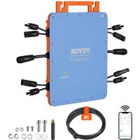
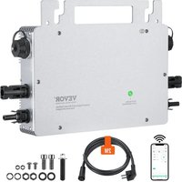
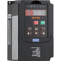
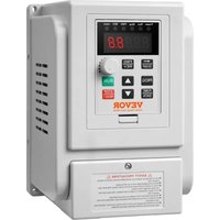
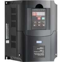
Inverter
MODEL:AT1-7500X
We continue to be committed to provide you tools with competitive price. "Save Half", "Half Price" or any other similar expressions used by us only represent the estimate of savings you might benefit from buying certain tools with us compared to the top brands and does not necessarily mean to cover all categories of tools offered by us. Are kindly reminded to verify carefully when you are placing an order with us if you actually saving half in comparison with the top major brands.
MODEL:AT1-7500X
NEED HELP? CONTACT US!
Have product questions? Need technical support? Please feel free contact us:
Technical Support and E-Warranty Certificate www.vevor.com/support
This is the original instruction, please read all manual instructions carefully before operating. VEVOR reserves a clear interpretation of user manual. The appearance of the product shall be subject to the product you received. Please forgive us that we won't inform you there are any technology or software updates on our product.
IMPORTANT SAFEGUARDS

Read all safety warnings, instructions, illustrations and specifications provided with this inverter. Failure to follow all instructions listed below may result in electric shock, fire and/or serious injury.
WARNING :
This equipment is a high voltage device, please do not attempt to disassemble this equipment at any time to avoid danger. After a device failure, if the external switch fails to restart the device, please contact yoreseller for handling.
WARNING: ELECTRICAL SHOCK AND FIRE HAZARD!
- Failure to comply with this instruction could result in an electrical failure fire and electrocution.
- DO NOT DISASSEMBLE.
- Do not submerge inverter.
- Do not connect two or more transformers in parallel
- Plug the power supply unit directly into a GFCI wet location outlet .
- Do not use an extension cord
- Installation of this inverter and related wiring must be done by a qualified electrician in compliance with all applicable electrical codes.
WARNING :
Changes or modifications to this unit not expressly approved by the party responsible for compliance could void the users authority to operate the equipment.
SAVE THESE INSTRUCTIONS
FCC Information
CAUTION: Changes or modifications not expressly approved by the party responsible for compliance could void the user's authority to operate the equipment!
This device complies with Part 15 of the FCC Rules. Operation is subject to the following two conditions:
1) This product may cause harmful interference.
2) This product must accept any interference received, including interference that may cause undesired operation.
WARNING: Changes or modifications to this product not expressly approved by the party.responsible for compliance could void the user's authority to operate the product.
Note: This product has been tested and found to comply with the limits a Class B digital device pursuant to Part 15 of the FCC Rules, These rules are designed to provide reasonable protection against harmful interference in a residential installation.
This product generates, uses and can radiate radio frequency energy, and if not installed and used in accordance with the instructions, may cause harmful interference to radio communications. However, there is no guarantee that interference will not occur in a particular installation. If this product does cause harmful interference to radio or television reception, which can be determined by turning the product off and on, the user is encouraged to try to correct the interference by one or more of the following measures.
- Reorient or relocate the receiving antenna.
- Increase the distance between the product and receiver.
- Connect the product to an outlet on a circuit different from that to which the receiver is connected.
- Consult the dealer or an experienced radio/TV technician for assistance.
Correct Disposal
This product is subject to the provision of European Directive 2012/19/EC. The symbol showing a wheelie bin crossed through indicates that the product requires separate refuse collection in the European Union. This applies to the product
and all accessories marked with this symbol. Products marked as such may not be discarded with normal domestic waste, but must be taken to collection point for recycling electrical and electronic device
1. Product information
The manual provides precautions and guidance for user type selection, installation, parameter setting, site commissioning, fault diagnosis and daily maintenance and maintenance
1.1 Inverter series
| AT901 series | Braking Resistor | |||||
| Model | Adaptive motor | Output Current:A | W | Ohm | ||
| KW | HP | |||||
| 22 | 901-7K5G1 | 7.5 | 10 | 34.0 | 600 | 40 |
1.2 Product Specification
| Project | Standard | |
| Basic Function | System | Current vector universal frequency converter |
| Drive | High-efficiency drive of the Induction Motor | |
| Maximal Frequency | Vector control: 0-500Hz | |
| V/F control: 0-3200Hz. | ||
| Carrier Frequency | 0.5KHz-16KHz | |
| The carrier frequency can be adjusted | ||
| Frequency resolution | Digital setting: 0.01Hz | |
| Simulation setting: ±0.025% | ||
| Control Mode | Open-loop vector control (SVC) | |
| V/F control | ||
| Starting torque | Type-G Mode: 0.3Hz/150% (SVC). | |
| Type-P Mode: 0.3Hz/100% | ||
| Range of ADJ | 1: 100(SVC) | |
| Stable speed | ±0.5%(SVC) | |
| Overload capacity | Type G:150% Rated Current 120s;180% for Type P:120% Rated Current for 60s;150% f | |
| Torque rise | Automatic torque increase; | |
| V/F curve | Three ways: straight line; multi-point; N | |
| Curve Acc/Dec mode | Line or S curve acceleration and deceleration mode, four Acc/Dec times, Acc/Dec time ratio 0.0-6500.0s | |
| DC Braking | Brake frequency: 0.00Hz-Maximum frequency; Brake time:.0s-36.0s Brake current value: 0.0% -100.0% | |
| Jog control | Jog frequency range: 0.00Hz-50.00Hz; Acc & Dec time: 0.0s-6500.0s. | |
| Up to 16 segment speed runs with a built-in PLC or control | ||
| built-in PID | It can easily realize the process control closed-loop control system | |
| AVR Function | When the input voltage jitter, the output | |
| Stall control | Automatically limited the current and voltage to prevent frequent over voltage tripping. | |
| Fast current limiting | Minimize the over current fault and protect normal operation of the frequency converter | |
| Torque limit | Automatically limit the torque during operation | |
| Instant power | When instantaneous power failure is | |
| Timing | Set the time range of 0.0Min-6500.0Min. | |
| Operating | Command source | Control panel,Control terminal,Serial port,car be switched in multiple ways |
| Frequency source | Panel potentiometer, Number given,External analog voltage/current input, and serial port input.can be switched in multiple ways | |
| Input Terminal | Five digital input terminals | |
| 1 analog quantity input terminal; | ||
| One 0-10V voltage or 0-20mA current input | ||
| Output Terminal | 1 digital output terminal | |
| 1 relay output terminal(TA,TB,TC) | ||
| 1 analog output terminal, supporting 0-10V 0-20mA voltage output | ||
| Protection function | Power on motor short circuit detection, input and output phase loss protection, over current protection, over voltage protection, under voltage protection, overheating protection and overload protection,etc | |
| Loop The environment | Use place | Indoor, not direct sunlight, no dust, corrosive gas, combustible gas, oil fog, steam, water salt, etc |
| Above sea level | under 1000m 2C116699 | |
| Ambient temperature | -10°C ~ + 40°C (ambient temperature is 4~50°C, please decrease the amount) | |
| humidity | Less than 95%RH, anhydrous condensation | |
| vibrate | Less than 5.9m/s (0.6g) | |
1.3 Description of the control loop and the main loop terminal
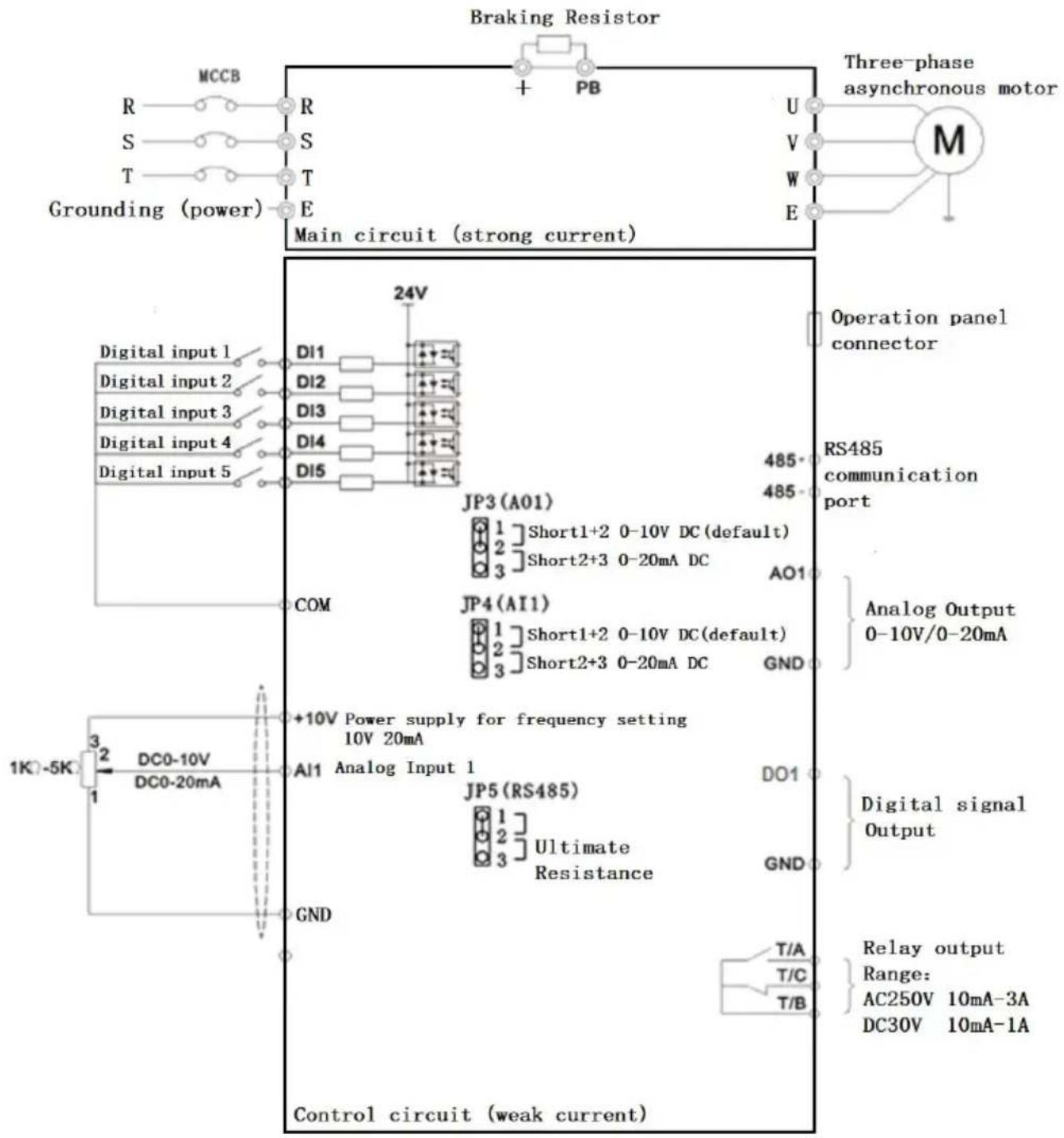
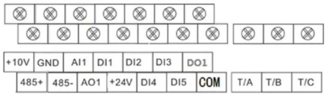
Figure 1-3-1 0.75-11.0KW wiring diagram control terminal description
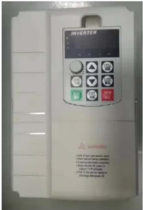
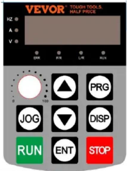
2. Operation and display
Function indicator lamp description
Hz: Frequency display indicator lamp
V: Voltage indicator lamp
A: Current indicator lamp
ERR: fault indicator lamp
F/R: Forward and Reverse indicator lamp
L / R: Communication control indicator lamp
RUN: Running indicator lamp
| Key symbol | Name | Function declaration |
| PRG | Programming key | Menu enters or exits, with parameter modification |
| ENT | Determine the key | Enter the menu and confirm the parameter setting |
| ▲ | Upper key | Increment of data or function codes |
| ▼ | Down key | Diminishing data or function codes |
| DISP | Shift key | Select the parameter modifier bit and the display contents |
| RUN | Run the key | Start the inverter under the keyboard operation mode |
| STOP | Stop / Reset key | Stop / reset operation, |
| JOG | Jog key | Limited to the P08.01 function code |
Set the parameter method:
- Press the PRG button to display the P 0.00,
- The and DISP keys select the parameter number to modify, and the ENTER key enters the parameter,
- ▲▼ and DISP keys modify parameter values, ENTER key save parameters,
-
If you need to modify other parameters, repeat 2,3, steps, such as modification completion, Return to the frequency interface using the PRG key.
-
Summary table of functional parameters:
| P00, Monitoring group | |||
| P00.00 | running frequency | 0.00 ~ 320.00Hz (P01.22=2) | - |
| P00.01 | Set the Frequency | 0.0 ~ 3200.0Hz (P01.22=1) | - |
| P00.02 | Busbar voltage (V) | 0.0V ~ 3000.0V | - |
| P00.03 | Output voltage (V) | 0V ~ 1140V | - |
| P00.04 | Output Current (A) | 0.00A ~ 655.35A | - |
| P00.05 | Output power (kW) | 0 ~ 32767 | - |
| P00.06 | Output torque (%) | -200.0% ~ 200.0% | - |
| P00.07 | DI input state | 0 ~ 32767 | - |
| P00.08 | DO output state | 0 ~ 1023 | - |
| P00.09 | AI1 voltage (V) | 0.01V | - |
| P00.10 | AI2 Voltage (V) or current (mA | 0.00V ~ 10.57V0.00mA ~ 20.00mA | - |
| P00.12 | count value | 0 ~ 65535 | - |
| P00.13 | Length value | 0 ~ 65535 | - |
| P00.14 | Load speed display | 0 ~ 65535 | - |
| P00.15 | PID setting | 0 ~ 65535 | - |
| P00.16 | PID feedback | 0 ~ 65535 | - |
| P00.17 | PLC stage | 0 ~ 65535 | - |
| P00.18 | Pulse input frequency | 0 ~ 100kHz | - |
| P00.19 | Feedback speed (Hz) | -320.00Hz ~ 320.00Hz | - |
| P00.20 | Runtime Remaining | 0.0 ~ 6500.0Min | - |
| P00.21 | AI1 Voltage before correction | 0.000V ~ 10.570V | - |
| P00.22 | AI2 Voltage/Current before correction | 0.000V ~ 10.570V0.000mA ~ 20.000mA | - |
| P00.24 | linear speed | 0 ~ 65535m/Min | - |
| P00.25 | Current power time | 0 ~ 6500Min | - |
| P00.26 | Current running time | 0.0 ~ 6500.0Min | - |
| P00.28 | Communication setting | -100.00% ~ 100.00% | - |
| P00.30 | Frequency X Display | 0.00Hz ~ 500.00Hz | - |
| P00.31 | Frequency Y Display | 0.00Hz ~ 500.00Hz | - |
| P00.32 | View any memory address value | 0 ~ 65535 | - |
| P00.35 | Target torque, (%) | 0.0°~ 359.9° | - |
| P00.37 | Power factor Angle | - | |
| P00.39 | Target voltage of VF separating | 0V ~ Motor rated voltage | - |
| P00.40 | Output voltage of VF separating | 0V ~ Motor rated voltage | - |
| P00.41 | DI input status display | - | - |
| P00.42 | DO input status display | - | - |
| P00.43 | DI function status display 1 | (function 01. function 40)- | - |
| P00.44 | DI function status visual display | (Function 41. Function 80)- | - |
| P00-45 | fault message | - | - |
| P00-59 | Set the frequency of (%) | -100.00% ~ 100.00% | - |
| P00-60 | Running frequency (%) | -100.00% ~ 100.00% | - |
| P00-61 | Inverter state | 0 ~ 65535 | - |
| ★—modifiable parameter under any condition ★—not modifiable parameter under run status ●—the actual detected parameter, not modifiable | ||||
| FC | name | Set range | Factory value | modify |
| P01 Basic functional Group | ||||
| P01.00 | G/P type | 1: Type G (constant torque lo model) 2: Type P (fan and water pu model) | 1 | ☆ |
| P01.01 | 1. Motor control mode | 0: Speed Sensorless Vector Control 2: V/F control model | 2 | ★ |
| P01.02 | Operation command | 0: Operation panel run comma channel ("L/R" lights off) | 0 | ☆ |
| channel | 1: Terminal Run channel ("L/R lights on")2: Communication command channel("L/R" lights flashing) | |||
| P01.03 | Main frequency source X | 0: Digital set (preset frequency P01.08, keypad ▲/▼ key,powe loss)1: Digital set (preset frequency P01.08, keypad ▲/▼ key,Powe drop memory)2: AI1 analog set (0-10V);3: AI2 analog set(0-10V or 20mA);4: Panel Potentiometer;5: Pulse set (0~50KHZ DI5);6: Multistage speed run set7: Simple PLC set;8: PID Control set;9: Communication set. | 4 | ★ |
| P01.04 | Secondary frequency source Y | Same as P01.03 (Main frequency source X) set | 0 | ★ |
| P01.05 | Limit selection of Y when frequency superposition | 0: Compared to the 【P01.10】 Maximum frequency1: Relative to the frequency source X | 0 | ☆ |
| P01.06 | Limit of Y when frequency superposition | 0% ~150% | 100% | ☆ |
| P01.07 | Frequency source | Single digit: Frequency source selection0: Main frequency source X1: Main and Secondary operati | 00 | |
| results (operation relationship determined by Ten digits)2: Main frequency X and Secondary frequency Y switch3: Switch between main frequency X and Main and Secondary operation results4: The frequency Y switches wMain and Secondary operation resultsTen digits: Frequency operation relationship of X and Y0: X +Y1: X -Y2: Maximum of the Two, 3: Minimum of the Two. | ||||
| P01.08 | Preposition frequency | 0.00Hz ~ Maximum frequenc【P01.10】 | 50.00Hz | ☆ |
| P01.09 | Running direction | 0: Consistent direction, 1: Opposite direction | 0 | ☆ |
| P01.10 | Maximum output frequency | Vector: 50.00Hz ~ 500.00HzV/F: 50.00Hz ~2000.00Hz | 50.00Hz | ★ |
| P01.11 | Upper limit frequency source | 0: 【P01.12】 Set up1: AI1 Set up2: AI2 Set up3: AI3 Set up4: Pulse set (0~50KHZ DI5);5: Communication Setup | 0 | ★ |
| P01.12 | Upper limiting frequency | 【P01.14】 ~ 【P01.10】 | 50.00Hz | ☆ |
| P01.13 | Upper limit frequency bias | 0.00Hz ~ 【P01.10】 | 0.00Hz | ☆ |
| P01.14 | Lower limit frequency | 0.00Hz ~ 【P01.12】 | 0.00Hz | ☆ |
| P01.15 | Carrier frequency | 0.5kHz ~ 16.0kHz | For Mode | ☆ |
| P01.16 | Carrier frequency Adjust with temperature | 0: No,1: Yes | 1 | ☆ |
| P01.17 | Acceleration time 1 | 0.00s ~ 650.00s (P01.19=2)0.0s ~ 6500.0s (P01.19=1)0s ~ 65000s (P01.19=0)Reference frequency 【P01.25】 | For Mode | ☆☆ |
| P01.18 | Deceleration time 1 | |||
| P01.19 | Time unit of Acceleration and deceleration time | 0: 1 seconds1: 0.1 seconds2: 0.01 seconds | 1 | ☆ |
| P01.21 | Bias frequency of frequency Y when superposition | 0.00Hz ~ Maximum output frequency【P01.10】 | 0.00Hz | ☆ |
| P01.22 | Resolution of Frequency | Resolution of all frequency commands. | 2 | ★ |
| P01.23 | Power down memory for Digital Frequency setting | 0: No memory 1: Memory | 0 | ☆ |
| P01.24 | Motor parameter group selection | 0: Motor parameter group 1, 1: Motor parameter group 2. | 0 | ★ |
| P01.25 | Reference frequency of Acceleration and deceleration time | 0: Maximum frequency 【P01.101: Setting frequency 2:100Hz | 0 | ★ |
| P01.26 | Runtime frequency instruction UP/DOWN | 0: Operation frequency, 1: Setting frequency | 0 | ★ |
| benchmark | ||||
| P01.27 | Command sourcebundledfrequency source | Single digit: Operation Panelcommand binding frequencysource selection0: No binding 1: Digital set2: AI1 3: AI2 4: AI35: Pulse set (0~50KHZ DI5);6: Multi segment speed;7: Simple PLC8:PID9: Communication SetTen digit: Terminal commandbinding frequency sourcesession100 digit: communicationcommand binding frequencysource selectionThousand digit: Automatically rthe binding frequency sourcesession | 0000 | ☆ |
| P02 Asynchronous Motor parameter group 1 | ||||
| P02.00 | Motor type | 0: Ordinary asynchronous moto1: Variable frequencyasynchronous motor | 0 | ★ |
| P02.01 | Rated power ofmotor | 0.1kW ~ 400.0kW | Accordingto theModelOf theInverter | ★ |
| P02.02 | Rated voltage ofMotor | 1V ~ 2000V | ★ | |
| P02.03 | Rated current ofMotor | 0.01A ~ 655.35A(Inverter power <=55kW)0.1A ~ 6553.5A(Inverter power> 55kW) | ★ | |
| P02.04 | Rated frequency of motor | 0.01Hz~ Maximum output frequency【P01.10】 | ★ | |
| P02.05 | Rated speed of motor | 1rpm ~ 65535rpm | ★ | |
| P02.06 | Stator resistance of motor | 0.001Ω ~ 65.535Ω (Inverter power <=55kW)0.0001Ω ~ 6.5535Ω (Inverter power> 55kW) | Tuning Parameter | ★ |
| P02.07 | Rotor resistance of Motor | 0.001Ω ~ 65.535Ω (Inverter power <=55kW)0.0001Ω ~ 6.5535Ω (Inverter power> 55kW) | ★ | |
| P02.08 | Leak resistance of Motor | 0.01mH ~ 655.35mH(Inverter power <=55kW)0.001Mh ~ 65.535mH(Inverter power> 55kW) | ★ | |
| P02.09 | Mutual resistance of Motor | 0.1mH ~ 6553.5mH (Inverter power <=55kW)0.01mH ~ 655.35mH(Inverter power> 55kW) | ★ | |
| P02.10 | No-load current of the Motor | 0.01A ~ P02.03 (Inverter power <=55kW)0.1A ~ P02.03 (Inverter power > 55kW) | ★ | |
| P02.37 | Tuning selection | 0: no-operation1: Tuning at Motor stationary2: Motor dynamic tuning3: Tuning at Motor completely stationary 2 | 0 | ★ |
| P03 Vector control parameters of motor group1 | ||||
| P03.00 | Speed loop proportional 1 | 1 ~ 100 | 30 | ☆ |
| P03.01 | Speed loop integration time | 0.01s ~ 10.00s | 0.50s | ☆ |
| P03.02 | Switch frequency 1 | 0.00 ~ 【P03.05】 | 5.00Hz | ☆ |
| P03.03 | Speed loop proportional 2 | 1 ~ 100 | 20 | ☆ |
| P03.04 | Speed loop integration time 2 | 0.01s ~ 10.00s | 1.00s | ☆ |
| P03.05 | Switch frequency 2 | P03.02 ~Maximum output frequency【P01.10】 | 10.00Hz | ☆ |
| P03.06 | Vector control of the shift gain | 50% ~ 200% | 100% | ☆ |
| P03.07 | SVC torque filtering time constants | 0.000s ~ 0.100s | 0.050s | ☆ |
| P03.09 | Torque upper lim source under speed control mode | 0: P03.10 setting 1: AI1; 2: AI2; 3: AI3; 4: Pulse set (DI5); 5: Communication Setting; 6: MIN (AI1, AI2) 7: MAX (AI1, AI2) | 0 | ☆ |
| P03.10 | Upper torque lim under speed control mode | 0.0% ~ 200.0% | 150.0% | ☆ |
| P03.13 | Proportional gain of excitation regulation | 0 ~ 60000 | 2000 | ☆ |
| P03.14 | Integral gain of excitation regulation | 0 ~ 60000 | 1300 | ☆ |
| P03.15 | Proportional gain | 0 ~ 60000 | 2000 | ☆ |
| of torque regulation | ||||
| P03.16 | Integral gain of torque regulation | 0 ~ 60000 | 1300 | ☆ |
| P04 V/F Control Parameters | ||||
| P04.00 | VF curve setting | 0: linear curve V/ F1: Multipoint curve V/ F2: Decreasing torque curve 1(Square curve)3: Decreasing torque curve 2(1.2 power)4: Decreasing torque curve 2(1.4 power)6: Decreasing torque curve 2(1.6 power)8: Decreasing torque curve 2(1.8 power)10: VF completely separation mode11: VF semi-separation mode | 0 | ★ |
| P04.01 | Torque boost setting | 0.0% (Automatic lifting torque)0.1%~30.0% | By Model | ☆ |
| P04.02 | Torque boost cutoff point | 0.00Hz ~ Maximum output frequency【P01.10】 | 50.00Hz | ★ |
| P04.03 | Multi-point V/F Freq. 1 | 0.00Hz ~ 【P04.05】 | 0.00Hz | ★ |
| P04.04 | Multi-point V/F Voltage 1 | 0.0% ~ 100.0% | 0.0% | ★ |
| P04.05 | Multi-point V/F Freq. 2 | 【P04.03】 ~ 【P04.07】 | 0.00Hz | ★ |
| P04.06 | Multi-point V/F Voltage 2 | 0.0% ~ 100.0% | 0.0% | ★ |
| P04.07 | Multi-point V/F Freq. 3 | 【P04.05】~ Motor Rated frequency 【P02.04】 | 0.00Hz | ★ |
| P04.08 | Multi-point V/F Voltage 3 | 0.0% ~ 100.0% | 0.0% | ★ |
| P04.09 | V/F control Slip frequency compensation | 0.0% ~ 200.0% | 0.0% | ☆ |
| P04.10 | V/F Over excitation gain | 0 ~ 200 | 64 | ☆ |
| P04.11 | Oscillation suppression gain for V/F | 0 ~ 100 | By Model | ☆ |
| P04.13 | Voltage source b VF separated | 0: Digital Settings 【P04.14】1: AI1 2: AI23: AI34: Pulse Setting (DI5)5: Multiple instruction6: Simple PLC7: The PID8: communication SettingNote: 100.0%, corresponding to the motor rated voltage | 0 | ☆ |
| P04.14 | Voltage for VF separation | 0V ~ Motor rated voltage | 0V | ☆ |
| P04.15 | Voltage rise time of VF separation | 0.0s ~ 1000.0sNote: Time when 0V rises to rated voltage of motor。 | 0.0s | ☆ |
| P04.16 | Voltage dorp time of VF separation | 0.0s ~ 1000.0sNote: Time when Rated voltag of motor dorp to 0V | 0.0s | ☆ |
| P04.17 | Shutdown mode of VF separation | 0: The frequency and voltage drop to 0 separately;1: Frequency drops after the Voltage drop to 0 | 0 | ☆ |
| P04.18 | Over-current stall action current | 50% ~ 200% | 150% | ★ |
| P04.19 | Suppression of Over current stall | 0: Disable, 1: Enable. | 1 | ★ |
| P04.20 | Suppression's gain of Over current stall | 0 ~ 100 | 20 | ☆ |
| P04.21 | Compensation coefficient of action Over current stall | 50% ~ 200% | 50% | ★ |
| P04.22 | Over-voltage stall action voltage | 650.0V ~ 800.0V | 760.0V | ★ |
| P04.23 | Suppression of Over-voltage stall | 0: Disable, 1: Enable. | 1 | ★ |
| P04.24 | Suppression's Freq. gain of Over-voltage stall | 0 ~ 100 | 30 | ☆ |
| P04.25 | Suppression's Voltage gain of Over-voltage stall | 0 ~ 100 | 30 | ☆ |
| P04.26 | Maximum rise frequency limit fo Over-voltage stall | 0 ~ 50Hz | 5Hz | ★ |
| P05 group, Input Parameters | ||||
| P05.00 | DI1 terminal function | 0: No function; 1: Forward running(FWD) or Running; 2:Reverse running (REV) or Forward/Reverse switch 3: three-wire running control 4: forward jog control (FJOG) 5: Reverse jog control (RJOG) | 1 | ★ |
6: Freq. Increase(Terminal UP
7: Freq. decrease(Terminal DOWN)
8: Free shutdown control
9: External reset signal input(RST)
10: Suspend operation;
11: External fault normally-ope (NO) input
12: Multi-speed 1
13: Multi-speed 2
14: Multi-speed 3
15: Multi-speed 4
16: ACC/DEC time select 1( T
17: ACC/DEC time select 2( T
18: Frequency source switch
19: UP/DOWN Freq. zero clearing (terminal, keyboard)
20: Run command Switch terminal 1
21: VFD ACC/DEC prohibit
22: PID control Pause
23:PLC state reset
24: Pendulum frequency Pause
25: Counter input
26: Counter reset
27: Length count input
28: Length reset
29: Torque control Disable
30: Pulse Setting (only DI5 setting, P05.04=30)
31: Reserved;
32: DC braking immediately;
33: External fault input (normal)
| closed, NC)34: Frequency modification Enables35: PID input signal reversed36: External parking terminal37: Run command Switch terminal 238: PID integral Pause;39: Frequency X switches withe Preset frequency40: Frequency Y switches withe Preset frequency41: Motor selection terminal43: The PID Parameters swit44: User defined fault 145: User defined fault 246: Speed control / Torque control switch47: Emergency stop48: External parking terminal49: Slow ate DC braking50: Run time cleared;51: Two-wire control / Three-w control switch52: Reversal Disable; | ||||
| P05.01 | DI2 terminal functional | 4 | ★ | |
| P05.02 | DI3 terminal functional | 9 | ★ | |
| P05.03 | DI4 terminal functional | 12 | ★ | |
| P05.04 | DI5 terminal function(only DI5 can | 13 | ★ | |
| setting Pulse function, P05.04=30) | ||||
| P05.10 | DI filtering time | 0.000s ~ 1.000s | 0.010s | ☆ |
| P05.11 | Terminal control Mode | 0: Two-wire control mode 1, 1: Two-wire control mode 2, 2: Three-wire control mode 1, 3: Three-wire control mode 2 | 0 | ★ |
| P05.12 | Frequency adjusting step size | 0.001Hz/s ~ 65.535Hz/s | 1.00Hz/s | ☆ |
| P05.13 | Min. input of Al curve 1 | 0.00V ~ P05.15 | 0.00V | ☆ |
| P05.14 | Corresponding value of Al curv 1's Min. input | -100.0% ~ +100.0% | 0.0% | ☆ |
| P05.15 | Max. input of Al curve 1 | P05.13 ~ +10.00V | 10.00V | ☆ |
| P05.16 | Corresponding value of Al curv 1's Max. input | -100.0% ~ +100.0% | 100.0% | ☆ |
| P05.17 | Al curve 1 filterin time | 0.00s ~ 10.00s | 0.10s | ☆ |
| P05.18 | Al curve 2's Mir input | 0.00V ~ P05.20 | 0.00V | ☆ |
| P05.19 | Corresponding value of Al curv 2's Min. input | -100.0% ~ +100.0% | 0.0% | ☆ |
| P05.20 | Max. input of Al | P05.18 ~ +10.00V | 10.00V | ☆ |
| P05.21 | Corresponding value of Al curv 2's Max. input | -100.0% ~ +100.0% | 100.0% | ☆ |
| P05.22 | AI curve 2 filterin time | 0.00s ~ 10.00s | 0.10s | ☆ |
| P05.23 | AI curve 3's Min input | -10.00V ~ P05.25 | -10.00V | ☆ |
| P05.24 | Corresponding value of AI curv 3's Min. input | -100.0% ~ +100.0% | 0.0% | ☆ |
| P05.25 | Max. input of A curve 3 | P05.23 ~ +10.00V | 10.00V | ☆ |
| P05.26 | Corresponding value of AI curv 3's Max. input | -100.0% ~ +100.0% | 100.0% | ☆ |
| P05.27 | AI curve 3 filterin time | 0.00s ~ 10.00s | 0.10s | ☆ |
| P05.28 | Min. value of Pulse input | -10.00V ~ P05.25 | 0.00V | ☆ |
| P05.29 | Corresponding value of Pulse's Min. input | -100.0% ~ +100.0% | 0.0% | ☆ |
| P05.30 | Max. value of Pulse input | P05.23 ~ +10.00V | 10.00V | ☆ |
| P05.31 | Corresponding value of Pulse's Max. input | -100.0% ~ +100.0% | 100.0% | ☆ |
| P05.32 | Pulse filtering time | 0.00s ~ 10.00s | 0.10s | ☆ |
| P05.33 | AI curve selection | Single bit: AI1 curve selection 1: AI curve 1 (2 PM, see P05.13 ~ P05.16 2: AI curve 2 (2 PM, see P05.18 ~ P05.21 3: AI curve 3 (2 PM, see P05.23 ~ P05.26 | 321 | ☆ |
| 4: AI curve 4(4 PM, see P24.00~P24.07)5: AI curve 4(4 PM, see P24.08~P24.15)Ten bit: AI2 curve selection (t same as Single bit 1~5) Hundred bit: AI3 curve setting (the same as above) | ||||
| P05.34 | The AI is below the minimum input setting selection | Single bit: AI1 below Min. inp setting0: Corresponding value of Mir input1: 0.0%Ten bit: AI2 below Min. inp setting(the same as Single bit 1~2) Hundred bit: AI3 below Min. inp setting(the same as above) | 000 | ☆ |
| P05.35 | DI1 delay time | 0.0s ~ 3600.0s | 0.0s | ★ |
| P05.36 | DI2 delay time | 0.0s ~ 3600.0s | 0.0s | ★ |
| P05.37 | DI3 delay time | 0.0s ~ 3600.0s | 0.0s | ★ |
| P05.38 | DI1-DI5 terminal valid mode selection | 0: High level effective, 1: Low level effectiveSingle Bit: DI1;Ten Bit: DI2;Hundreds Bit: DI3; Thousand Bit: DI4;Ten thousand Bit: DI5 | 00000 | ★ |
| P05.39 | DI6-D17 terminal valid mode selection | 0: High level effective, 1: Low level effectiveSingle Bit: DI6, | 00000 | ★ |
| Ten Bit: DI7 | ||||
| P06 group, Output Parameters | ||||
| P06.01 | DO1 output function selection | 0: No output1: Running indicator;2: Fault output (for free shutdofault)3: Freq. level detection signa1(P14T1)4: Frequency arrival indicator(FAR)5: VFD zero-speed running(When running)6: Motor overload Early- warnn9: The specified count is reach10: Length is reached11: The PLC cycle is complet12: Accumulated running time arrives13: Frequency limiting14: Torque limiting15: Ready to run16: AI1>AI217: Output freq. reaches Uppe limit18: Output freq. reaches Lowe limit(When running)19: Under pressure state outp20: Communication setting21: Location is complete(reserved) | 0 | ☆ |
| P06.02 | Control Board Relay(TA- TB- TC)FunctionSelection | 2 | ☆ | |
| 22: Location proximity (reserved 23: Zero-speed running 2 (als output when shutdown) 24: Accumulated power-on time arrives 25: Freq. level detection signa 2(P14T2) 26: Output freq. 1 reached 27: Output freq. 2 reached 28: Output Current 1 reached 29: Output Current 2 reached 30: Regularly reached 31: Input signal Al1 overrun 32: Load dropping 33: VFD reverse running 34: Zero-current state 35: The Power module temperature arrives 36: Output current out of lim 37:Output freq. reaches Lower limit(shutdown also output) 38: Fault output (all faults) 39: Motor overheating Early-warning 40: This running time arrives 41: Fault output (for free shutdown fault and no under pressure output) | ||||
| P06.07 | AO1 output function selection | 0: Operation freq., 1: Set freq. | 0 | ☆ |
| P06.08 | AO2 output function selection | 2: Output current, 3: Output torque, 4: Output power, 5: Output voltage, | 1 | ☆ |
| 6: Input pulse freq.7: AI1 8: AI29: AI310: Length11: Count value12: Communication setting,13: Motor speed14: Output Current. (100.0%Corresponding to 1000.0A)15: Output voltage (100.0%Corresponding to 1000.0V)16: Motor output torque(Percentage of actual valuerelative to motor rating)17: VFD output torque(Percentage of actual valuerelative to VFD rating) | ||||
| P06.10 | AO1 zero-bias coefficient | -100.0% ~ +100.0% | 0.0% | ☆ |
| P06.11 | AO1 gain | -10.00 ~ +10.00 | 1.00 | ☆ |
| P06.12 | AO2 zero-bias coefficient | -100.0% ~ +100.0% | 0.0% | ☆ |
| P06.13 | AO2 gain | -10.00 ~ +10.00 | 1.00 | ☆ |
| P06.17 | DO output delay time | 0.0s ~ 3600.0s | 0.0s | ☆ |
| P06.18 | RELAY output delay time | 0.0s ~ 3600.0s | 0.0s | ☆ |
| P06.19 | RELAY2 output delay time | 0.0s ~ 3600.0s | 0.0s | ☆ |
| P06.22 | DO output valid status selection | 0: Positive logic, 1: Anti-logic Single Bit: DO Ten bit: RELAY1 | 00000 | ☆ |
| Hundred Bit: RELAY2 | ||||
| P07 group, Start and Stop control Parameters | ||||
| P07.00 | Starting mode | 0: Direct start1: Start with speed tracking2: DC braking + start at sta frequency | 0 | ☆ |
| P07.01 | Speed tracking method | 0: Start with the shutdown frequency1: Start with the working frequency2: Start at the maximum frequency | 0 | ★ |
| P07.02 | Speed of Speed tracking | 1 ~ 100 | 20 | ☆ |
| P07.03 | Start frequency | 0.00Hz ~ 10.00Hz | 0.00Hz | ☆ |
| P07.04 | Start-frequency hold time | 0.0s ~ 100.0s | 0.0s | ★ |
| P07.05 | DC brake current at startup | 0% ~100% | 0% | ★ |
| P07.06 | DC brake time a startup | 0.0s ~100.0s | 0.0s | ★ |
| P07.07 | Accelerating and Decelerating mode | 0: linear Acc/Dec mode1: S curve Acc/Dec mode A2: S curve Acc/Dec mode B | 0 | ★ |
| P07.08 | Time ratio of Sta segment in S curve | 0.0% ~ (100.0%-P07.09) | 30.0% | ★ |
| P07.09 | Time ratio of Sta segment in S curve | 0.0% ~ (100.0%-P07.08) | 30.0% | ★ |
| P07.10 | Stop mode | 0: Decelerate to stop 1: Coast to stop | 0 | ☆ |
| P07.11 | Frequency threshold of DC brake | 0.00Hz ~ Maximum freq. 【P01.10】 | 0.00Hz | ☆ |
| P07.12 | DC brake delay time | 0.0s ~ 100.0s | 0.0s | ☆ |
| P07.13 | DC brake curren | 0% ~ 100% | 0% | ☆ |
| P07.14 | DC brake time a stop | 0.0s ~ 100.0s | 0.0s | ☆ |
| P07.15 | DC Brake utilization rate | 0% ~ 100% | 100% | ☆ |
| P07.18 | Speed tracking current | 30% ~ 200% | ★ | |
| P08 Group Keyboards and Display Parameters | ||||
| P08.01 | M key function | 0: The M key is invalid 1: Switch between Remote Control (Terminal or Communication control) and Operation Panel Control, when 【P01.02】 =1 or 2 2: FWD/REV switch 3: FJOG (Forward jog control 4: RJOG (Reverse jog control | 0 | ★ |
| P08.02 | STOP/RESET key function | 0: The STOP/RES key Only in panel control mode 1: The STOP/RES key Alway valid | 1 | ☆ |
| P08.03 | LED displays parameter 1in Operation status | 0000 ~ FFFF Bit00: Running Frequency 1 (H Bit01: Setting Frequency (Hz) Bit02: Bus Voltage (V) | 1F | ☆ |
| Bit03: Output Voltage (V) Bit04: Output current (A) Bit05: Output power (kW) Bit06: Output torque (%) Bit07: DI input status Bit08: DO output status Bit09: AI1 voltage (V) Bit10: AI2 voltage (V) Bit11: AI3 voltage (V) Bit12: Count value Bit13: Length value Bit14: Load speed display Bit15: PID settings | ||||
| P08.04 | LED displays parameter 2in Operation status | 0000 ~ FFFF Bit00: PID feedback Bit01: PLC stage Bit02: PULSE Input frequency (kHz) Bit03: Running Frequency 2 (H Bit04: Remaining runtime Bit05:AI1-corrected front voltage (V) Bit06:AI2-corrected front voltage (V) Bit07:AI3-corrected front voltage (V) Bit08: Line speed Bit09: Current Power Time (Hour) Bit10: Current Runtime (Min) Bit11:PULSE Input frequency (Hz) Bit12: Communication Setting Value | 0 | ☆ |
| Bit13: Encoder feedback speed (Hz) Bit14: Main Frequency X Display (Hz) Bit15: Secondary frequency Y Display (Hz) | ||||
| P08.05 | LED displays parameter in Sto status | 0000 ~ FFFF Bit00: Set Frequency (Hz) Bit01: Bus Voltage (V) Bit02: DI input status Bit03: DO output status Bit04: AI1 voltage (V) Bit05: AI2 voltage (V) Bit06: AI3 voltage (V) Bit07: Count value Bit08: Length value Bit09: PLC stage Bit10: Load speed Bit11: PID settings Bit12: PULSE Input frequency (kHz) | 33 | ☆ |
| P08.06 | Load speed display factor | 0.0001 ~ 6.5000 | 1.0000 | ☆ |
| P08.07 | Power module temperature | 0.0℃ ~ 100.0℃ | - | ● |
| P08.08 | Product number | - | - | ● |
| P08.09 | Cumulative running time | Oh ~ 65535h | - | ● |
| P09 group, auxiliary function | ||||
| P09.00 | Jog frequency | 0.00Hz ~ Maximum freq. 【P01.10】 | 2.00Hz | ☆ |
| P09.01 | Jog Acc time | 0.0s ~ 6500.0s | 20.0s | ☆ |
| P09.02 | Jog Dec time | Recommended time:0.4 ~ 4.0KW 7.5S5.5 ~ 30.0KW 15.0S37.0 ~ 132.0KW 40.0S160.0~ 630.0KW 60.0S | 20.0s | ☆ |
| P09.03 | Acceleration time2 | 15.0 | ☆ | |
| P09.04 | Deceleration time2 | ☆ | ||
| P09.05 | Acceleration time3 | ☆ | ||
| P09.06 | Deceleration time3 | ☆ | ||
| P09.07 | Acceleration time4 | ☆ | ||
| P09.08 | Deceleration time4 | ☆ | ||
| P09.09 | Hopping freq. 1 | 0.00Hz ~ Maximum freq.【P01.10】 | 0.00Hz | ☆ |
| P09.10 | Hopping freq. 2 | 0.00Hz | ☆ | |
| P09.11 | Hopping freq-range | 0.01Hz | ☆ | |
| P09.12 | Positive andReverse deadtime | 0.0s ~ 3000.0s | 0.0s | ☆ |
| P09.13 | Reversefrequencypermission | 0: Allowed; 1:Prohibit | 0 | ☆ |
| P09.14 | When the settingfreq. is lower thathe lower limit offreq. | 0: Run at a lower limit freque1: Stop2: zero-speed operation | 0 | ☆ |
| P09.15 | Drop control | 0.00Hz ~ 10.00Hz | 0.00Hz | ☆ |
| P09.16 | Settingcumulative power | Oh ~ 65000h | Oh | ☆ |
| P09.17 | Setting cumulative | Oh ~ 65000h | Oh | ☆ |
| P09.18 | Start protection | 0: Unprotected; | 0 | ☆ |
| P09.19 | Frequency detection value 1 (P14T1) | 0.00Hz ~ Maximum freq. 【P01.10】 | 50.00 Hz | ☆ |
| P09.20 | Frequency detection lag value (P14T1) | 0.0% ~ 100.0% (P14T1 level) | 5.0% | ☆ |
| P09.21 | Frequency reaches the detected width | 0.0% ~ 100.0% (Maximum frequency) | 0.0% | ☆ |
| P09.22 | Frequency hopping function During Acc and Dec. | 0: Invalid, 1: valid | 0 | ☆ |
| P09.25 | Switching freq. o acceleration time 1 and time 2 | 0.00Hz ~ Maximum freq. 【P01.10】 | 0.00Hz | ☆ |
| P09.26 | Switching freq. o deceleration time 1 and time 2 | 0.00Hz ~ Maximum freq. 【P01.10】 | 0.00Hz | ☆ |
| P09.27 | Terminal Jog priority | 0: Invalid, 1: valid | 0 | ☆ |
| P09.28 | Frequency detection value 2 (P14T2) | 0.00Hz ~ Maximum frequency | 50.00 Hz | ☆ |
| P09.29 | Frequency detection lag value (P14T2) | 0.0% ~ 100.0% (P14T2 level) | 5.0% | ☆ |
| P09.30 | Arbitrary arrival frequency | 0.00Hz ~ Maximum frequency | 50.00 Hz | ☆ |
| detection value 1 | ||||
| P09.31 | Arbitrary arrival frequency detected width 1 | 0.0% ~ 100.0% (Maximum frequency) | 0.0% | ☆ |
| P09.32 | Arbitrary arrival frequency detection value 2 | 0.00Hz ~ Maximum frequency | 50.00 Hz | ☆ |
| P09.33 | Arbitrary arrival frequency detected width 2 | 0.0% ~ 100.0% (Maximum frequency) | 0.0% | ☆ |
| P09.34 | Zero-current detection level | 0.0% ~ 300.0% 100.0% corresponds to the motor rated current | 5.0% | ☆ |
| P09.35 | Delay time of Current detect | 0.01s ~ 600.00s | 0.10s | ☆ |
| P09.36 | Current value of output over current | 0.0% (Not detect) 0.1% ~ 300.0% (Motor rated current) | 200.0% | ☆ |
| P09.37 | Delay time of Output Over current Detection | 0.00s ~ 600.00s | 0.00s | ☆ |
| P09.38 | Arbitrary arrival current 1 | 0.0% ~ 300.0% (Motor rated current) | 100.0% | ☆ |
| P09.39 | Arbitrary arrival current 1 width | 0.0% ~ 300.0% (Motor rated current) | 0.0% | ☆ |
| P09.40 | Arbitrary arrival current 2 | 0.0% ~ 300.0% (Motor rated current) | 100.0% | ☆ |
| P09.41 | Arbitrary arrival current 2 width | 0.0% ~ 300.0% (Motor rated current) | 0.0% | ☆ |
| P09.42 | Timer function selection | 0: Invalid, 1: valid | 0 | ☆ |
| P09.43 | Timer runtime | 0: P09.44 setting, | 0 | ☆ |
| selection | 1: AI12: AI23: AI3Analog input range correspond to the【P09.44】 | |||
| P09.44 | Timer running time | 0.0Min ~ 6500.0Min | 0.0Min | ☆ |
| P09.45 | AI1 input voltage protection value lower limit | 0.00V ~ P09.46 | 3.10V | ☆ |
| P09.46 | AI1 input voltage protection value upper limit | P09.45 ~ 10.00V | 6.80V | ☆ |
| P09.47 | Over temp. protection Value | 0℃ ~ 100 ℃ | 75℃ | ☆ |
| P09.48 | Cooling fan control | 0: Fan running during VDF running1: Always running when powe on; | 0 | ☆ |
| P09.49 | Wake up frequency | Hibernate frequency (P09.51) Maximum freq.【P01.10】 | 0.00Hz | ☆ |
| P09.50 | Wake up delay time | 0.0s ~ 6500.0s | 0.0s | ☆ |
| P09.51 | Sleep frequency | 0.00Hz ~ Wake-Up Frequency【P09.49】 | 0.00Hz | ☆ |
| P09.52 | Sleep delay time | 0.0s ~ 6500.0s | 0.0s | ☆ |
| P09.53 | Arrival time of th operation | 0.0 ~ 6500.0Min | 0.0Min | ☆ |
| P09.54 | Correction factor of Output power | 0.00% ~ 200.0% | 100.0% | ☆ |
| P10 group Fault and Protection | ||||
| P10.00 | Motor overload protection | 0: Disable, 1: Enable | 1 | ☆ |
| P10.01 | Motor overload protection gain | 0.20 ~ 10.00 | 1.00 | ☆ |
| P10.02 | Motor overload early-warning factor | 50 ~ 100% | 80% | ☆ |
| P10.07 | Short circuit to ground protection when power on | 0: Disable, 1: Enable | 1 | ☆ |
| P10.08 | Brake unit's starting voltage | 650.0V ~ 800.0V | 690V | ☆ |
| P10.09 | Automatic fault reset times | 0 ~ 20 | 0 | ☆ |
| P10.10 | DO action selection during automatic fault reset | 0: No Action 1: Action | 0 | ☆ |
| P10.11 | Interval for Automatic fault reset | 0.1s ~ 100.0s | 1.0s | ☆ |
| P10.12 | Input phase loss protection/ Power relay pull in protection | Single Bit: Input phase loss protection 0: Disable, 1: Enable Ten Bit: Power relay pull in protection 0: Disable, 1: Enable | 11 | ☆ |
| P10.13 | Output phase loss protection | 0: Disable, 1: Enable | 1 | ☆ |
| P10.14 | First-time failure type | 0: No fault 1: (Reserved) | - | ● |
| P10.15 | Second failure type | 2: Over-current in Acc process3: Over-current in Dec process4: Over-current in constant speed5: Over-voltage in Acc process6: Over-voltage in Dec process7: Over-voltage in constant speed8: Buffer resistance overload9: Under-voltage10: VFD overload11: Motor overload12: Input phase loss13: Output phase loss14: Power module is overheat15: External fault16: Communication exception17: Power relay is abnormal18: Abnormal current detection19: Motor tuning is abnormal21: Parameter read and write exception22: Other Hardware abnormal23: Motor short-circuit to grour26: Run-time arrival27: User Custom fault 128: User Custom fault 229: Power-on time arrives30: Load drop31: Runtime PID feedback is 40: Fast flow limit timeout41: Switch the motor during operation42: Speed deviation is too large | - | ● |
| P10.16 | Third (most recent) fault type | - | ● | |
| 43: Motor over-speed | ||||
| P10.17 | Frequency at the third (most recent) failure | - | - | ● |
| P10.18 | Current at the third (most recent) fault | - | - | ● |
| P10.19 | Bus voltage at the third (most recent) fault | - | - | ● |
| P10.20 | Input terminal status at the third (most recent) failure | - | - | ● |
| P10.21 | Output terminal status at the third (most recent) failure | - | - | ● |
| P10.22 | The Inverter status at the third (most recent) failure | - | - | ● |
| P10.23 | Power-on time for the third (most recent) failure | - | - | ● |
| P10.24 | Run time for the third (most recent) failure | - | - | ● |
| P10.27 | Frequency at the second failure | - | - | ● |
| P10.28 | Current at the second failure | - | - | ● |
| P10.29 | Bus voltage at the second fault | - | - | ● |
| P10.30 | Input terminal status for the second failure | - | - | ● |
| P10.31 | Output terminal status at the second failure | - | - | ● |
| P10.32 | The Inverter status at the second failure | - | - | ● |
| P10.33 | Power-on time for the second failure | - | - | ● |
| P10.34 | Run time for the second failure | - | - | ● |
| P10.37 | Frequency at the first failure | - | - | ● |
| P10.38 | Current at the fir failure | - | - | ● |
| P10.39 | Bus voltage at the first failure | - | - | ● |
| P10.40 | Input terminal status at the fir failure | - | - | ● |
| P10.41 | Output terminal status at the fir failure | - | - | ● |
| P10.42 | The Inverter status at the fir failure | - | - | ● |
| P10.43 | Power-on time for the first failure | - | - | ● |
| P10.44 | Run time for the | - | - | ● |
| first failure | ||||
| P10.47 | Fault protection action selection 1 | Single Bit: Motor overload (Err10)Ten Bit: Input phase loss, (Err11) Hundred Bit: Output phase loss (Err13)Thousand Bit: External fault (Err15)Ten thousand Bit: Communication exception, (Err16)0: Coast to stop;1: Stop by Stop mode【P07.10】2: Keep running; | 00000 | ☆ |
| P10.48 | Fault protection action selection 2 | Single Bit/Hundred Bit/Thousand Bit: (Reserved)Ten Bit: Parameter read and write exception (Err21)Ten thousand Bit: Run-time arrival (Err26)0: Coast to stop;1: Stop by Stop mode【P07.10】 | 00000 | ☆ |
| P10.49 | Fault protection action selection 3 | Single Bit: User Custom fault (Err27)Ten Bit:: User Custom fault (Err28)Hundred Bit: Power-on time arrives (Err29)Thousand Bit: Load drop (Err30: Coast to stop;1: Stop by Stop mode【P07.10】2: Jump to 7% of the Rated f of the Motor and keep running Operate return to Set freq. wh | 00000 | ☆ |
| load recovery Ten thousand Bit: PID feedback loss (Err31) 0: Coast to stop; 1: Stop by Stop mode【P07.10】 2: Keep running; | ||||
| P10.50 | Fault protection action selection 4 | Single Bit: Speed deviation to large (Err42) Ten Bit: Motor over-speed (Err43) Hundred Bit: (Reserved) Thousand Bit: Speed feedback error (Err52) 0: Coast to stop; 1: Stop by Stop mode【P07.10】 2: Keep running; | 00000 | ☆ |
| P10.54 | Keep running freq. selection when failure | 0: The current frequency 1: The setting frequency 2: Run at upper limit frequency 3: Run at lower limit frequency 4: Run at abnormal reserve frequency | 0 | ☆ |
| P10.55 | Abnormal reserve frequency | 0.0%~100.0% (100.0% corresponds to Max freq 【P01.10】 | 100.0% | ☆ |
| P10.59 | Instant power non-stop | 0: Invalid 1: Reduce the speed; 2: Deceleration stop | 0 | ☆ |
| P10.60 | The Pause judgment voltage of Instant power non-stop | 80.0% ~ 100.0% (Standard bus voltage) | 90.0% | ☆ |
| P10.61 | Voltage recovery Judgment time o Instant power | 0.00s ~ 100.00s | 0.50s | ☆ |
| non-stop | ||||
| P10.62 | The judgment voltage of Instant power non-stop | 60.0% ~ 100.0% (Standard buvoltage) | 80.0% | ☆ |
| P10.71 | Gain of Instant power non-stop | 0 ~ 100 | 40 | ☆ |
| P10.72 | Integral coefficient of Instant power non-stop | 0 ~ 100 | 30 | ☆ |
| P10.73 | Deceleration time of Instant power non-stop | 0 ~ 300.0s | 20.0s | ★ |
| P10.63 | Load drop protection selection | 0: Invalid, 1: valid | 0 | ☆ |
| P10.64 | Load drop detection level | 0.0 ~ 100.0% | 10.0% | ☆ |
| P10.65 | Load drop detection time | 0.0 ~ 60.0s | 1.0s | ☆ |
| P10.67 | Over-speed detection value | 0.0% ~ 50.0% (Max freq 【P01.10】) | 20.0% | ☆ |
| P10.68 | Over-speed detection time | 0.0s: Non-detectable 0.1 ~ 60.0s | 1.0s | ☆ |
| P10.69 | The detection value for Speed deviation too large | 0.0% ~ 50.0% (Max freq 【P01.10】) | 20.0% | ☆ |
| P10.70 | The detection time for Speed deviation too large | 0.0s: 0.1 ~ 60.0s | 5.0s | ☆ |
| P11 group PID function | ||||
| P11.00 | PID input channe | 0: P11.01 setting1: AI12: AI23: AI34: Pulse Setting (DI5)5: Communication Setting6: Multistage speed7: Keyboard encoder settings | 0 | ☆ |
| P11.01 | Digital reference input setting | 0.0~ 10.00 | 3.00 | ☆ |
| P11.02 | PID feedback channel | 0: AI11: AI2 2: AI33: AI1-AI24: Pulse Setting (DI5)5: Communication Setting6: AI1+AI27: MAX (|AI1|, |AI2|)8: MIN (|AI1|, |AI2|) | 0 | ☆ |
| P11.03 | PID polarity | 0: Positive direction,1: Negative direction | 0 | ☆ |
| P11.04 | Range of PID feedback | 0 ~ 100.00KG | 10.00 | ☆ |
| P11.05 | Proportional gain KP02 | 0.0 ~ 100.0 | 20.0 | ☆ |
| P11.06 | Integration time Ti1 | 0.01s ~ 10.00s | 2.00s | ☆ |
| P11.07 | Derivative time Td1 | 0.000s ~ 10.000s | 0.000s | ☆ |
| P11.08 | PID reversal cutoff freq | 0.00 ~ Maximum frequency | 2.00Hz | ☆ |
| P11.09 | The limit of PID deviation | 0.0% ~ 100.0% | 1.0% | ☆ |
| P11.10 | Differential limiter of PID | 0.00% ~ 100.00% | 0.10% | ☆ |
| P11.11 | PID Input signal change time | 0.00 ~ 650.00s | 0.00s | ☆ |
| P11.12 | PID feedback filtering time | 0.00 ~ 60.00s | 0.00s | ☆ |
| P11.13 | The PID output filtering time | 0.00 ~ 60.00s | 0.00s | ☆ |
| P11.15 | Proportional gain KP03 | 0.0 ~ 100.0 | 20.0 | ☆ |
| P11.16 | Integration time Ti2 | 0.01s ~ 10.00s | 2.00s | ☆ |
| P11.17 | Derivative time Td2 | 0.000s ~ 10.000s | 0.000s | ☆ |
| P11.18 | The PID parameter switching conditions | 0: No switch 1: Switch via the DI termina 2: Automatic switch according the deviation | 0 | ☆ |
| P11.19 | The PID parameter switching Deviation 1 | 0.0% ~ P11.20 | 20.0% | ☆ |
| P11.20 | The PID parameter switching Deviation 2 | P11.19 ~ 100.0% | 80.0% | ☆ |
| P11.21 | Initial value of PI | 0.0% ~ 100.0% | 0.0% | ☆ |
| P11.22 | Holding time of PID Initial | 0.00 ~ 650.00s | 0.00s | ☆ |
| P11.23 | Max positive deviation of Two output | 0.00% ~ 100.00% | 1.00% | ☆ |
| P11.24 | Max deviation deviation of Two output | 0.00% ~ 100.00% | 1.00% | ☆ |
| P11.25 | The PID integral property | Single Bit: Integral separation 0: Invalid, 1: valid Ten Bit: when the frequency reaches the limits 0: Continue integral regulation 1: Stop integral regulation | 00 | ☆ |
| P11.26 | PID feedback loss detection values | 0.1% ~ 100.0% (0.0%: Not detection) | 0.0% | ☆ |
| P11.27 | PID feedback loss detection time | 0.0s ~ 20.0s | 0.0s | ☆ |
| P11.28 | The PID shutdown operation | 0: Stop without PID operation 1: Stop with PID operation | 0 | ☆ |
| P12 group -Swing frequency, Fixed length and Counting | ||||
| P12.00 | Mode of Swing freq setting | 0: Relative to the Central frequency【P01.07】 1: Relative to the Max freq 【P01.10】 | 0 | ☆ |
| P12.01 | Range of Swing frequency | 0.0% ~ 100.0% | 0.0% | ☆ |
| P12.02 | The Range of th jump freq | 0.0% ~ 50.0% | 0.0% | ☆ |
| P12.03 | Cycle of Swing frequency | 0.1s ~ 3000.0s | 10.0s | ☆ |
| P12.04 | Rise time of swing freq 's triangular wave | 0.1% ~ 100.0% | 50.0% | ☆ |
| P12.05 | Setting length | 0m ~ 65535m | 1000m | ☆ |
| P12.06 | Actual length | 0m ~ 65535m | 0m | ☆ |
| P12.07 | Number of pulse per Meter | 0.1 ~ 6553.5 | 100.0 | ☆ |
| P12.08 | Setting Count value | 1 ~ 65535 | 1000 | ☆ |
| P12.09 | Specifies Count value | 1 ~ 65535 | 1000 | ☆ |
| P13 group Multistage speed, simple PLC | ||||
| P13.00 | Multistage speed 0 (MS0) | -100.0% ~ 100.0% (Max fre 【P01.10】) | 0.0% | ☆ |
| P13.01 | Multistage speed 1 (MS1) | 0.0% | ☆ | |
| P13.02 | Multistage speed 2 (MS2) | 0.0% | ☆ | |
| P13.03 | Multistage speed 3 (MS3) | 0.0% | ☆ | |
| P13.04 | Multistage speed 4 (MS4) | 0.0% | ☆ | |
| P13.05 | Multistage speed 5 (MS5) | 0.0% | ☆ | |
| P13.06 | Multistage speed 6 (MS6) | 0.0% | ☆ | |
| P13.07 | Multistage speed 7 (MS7) | 0.0% | ☆ | |
| P13.08 | Multistage speed 8 (MS8) | 0.0% | ☆ | |
| P13.09 | Multistage speed 9 (MS9) | 0.0% | ☆ | |
| P13.10 | Multistage speed 10 (MS10) | 0.0% | ☆ | |
| P13.11 | Multistage speed 11 (MS11) | 0.0% | ☆ | |
| P13.12 | Multistage speed 12 (MS12) | 0.0% | ☆ | |
| P13.13 | Multistage speed 13 (MS13) | 0.0% | ☆ | |
| P13.14 | Multistage speed 14 (MS14) | 0.0% | ☆ | |
| P13.15 | Multistage speed 15 (MS15) | 0.0% | ☆ | |
| P13.16 | Simple PLC operation mode | 0: End of single operation 1: Final value at end of single operation 2: Always cycle | 0 | ☆ |
| P13.17 | PLC running stat saving after power off | Single Bit: when Power drop Ten Bit: when Stop 0: Not save 1: Saving. | 00 | ☆ |
| P13.18 | Multistage speed 0 runtime | 0.0s (h) ~ 6553.5s (h) | 0.0s (h) | ☆ |
| P13.19 | Acc/Dec time of MS 0 | 0 ~ 3 | 0 | ☆ |
| P13.20 | Multistage speed 1 runtime | 0.0s (h) ~ 6553.5s (h) | 0.0s (h) | ☆ |
| P13.21 | Acc/Dec time of MS 1 | 0 ~ 3 | 0 | ☆ |
| P13.22 | Multistage speed 2 runtime | 0.0s (h) ~ 6553.5s (h) | 0.0s (h) | ☆ |
| P13.23 | Acc/Dec time of MS 2 | 0 ~ 3 | 0 | ☆ |
| P13.24 | Multistage speed 3 runtime | 0.0s (h) ~ 6553.5s (h) | 0.0s (h) | ☆ |
| P13.25 | Acc/Dec time of | 0 ~ 3 | 0 | ☆ |
| MS 3 | ||||
| P13.26 | Multistage speed4 runtime | 0.0s (h) ~ 6553.5s (h) | 0.0s (h) | ☆ |
| P13.27 | Acc/Dec time ofMS 4 | 0 ~ 3 | 0 | ☆ |
| P13.28 | Multistage speed5 runtime | 0.0s (h) ~ 6553.5s (h) | 0.0s (h) | ☆ |
| P13.29 | Acc/Dec time ofMS 5 | 0 ~ 3 | 0 | ☆ |
| P13.30 | Multistage speed6 runtime | 0.0s (h) ~ 6553.5s (h) | 0.0s (h) | ☆ |
| P13.31 | Acc/Dec time ofMS 6 | 0 ~ 3 | 0 | ☆ |
| P13.32 | Multistage speed7 runtime | 0.0s (h) ~ 6553.5s (h) | 0.0s (h) | ☆ |
| P13.33 | Acc/Dec time ofMS 7 | 0 ~ 3 | 0 | ☆ |
| P13.34 | Multistage speed8 runtime | 0.0s (h) ~ 6553.5s (h) | 0.0s (h) | ☆ |
| P13.35 | Acc/Dec time ofMS 8 | 0 ~ 3 | 0 | ☆ |
| P13.36 | Multistage speed9 runtime | 0.0s (h) ~6553.5s (h) | 0.0s (h) | ☆ |
| P13.37 | Acc/Dec time ofMS 9 | 0 ~ 3 | 0 | ☆ |
| P13.38 | Multistage speed10 runtime | 0.0s (h) ~ 6553.5s (h) | 0.0s (h) | ☆ |
| P13.39 | Acc/Dec time ofMS 10 | 0 ~ 3 | 0 | ☆ |
| P13.40 | Multistage speed11 runtime | 0.0s (h) ~6553.5s (h) | 0.0s (h) | ☆ |
| P13.41 | Acc/Dec time ofMS 11 | 0 ~ 3 | 0 | ☆ |
| P13.42 | Multistage speed 12 runtime | 0.0s (h) ~ 6553.5s (h) | 0.0s (h) | ☆ |
| P13.43 | Acc/Dec time of MS 12 | 0 ~ 3 | 0 | ☆ |
| P13.44 | Multistage speed 3 runtime | 0.0s (h) ~ 6553.5s (h) | 0.0s (h) | ☆ |
| P13.45 | Acc/Dec time of MS 3 | 0 ~ 3 | 0 | ☆ |
| P13.46 | Multistage speed 14 runtime | 0.0s (h) ~ 6553.5s (h) | 0.0s (h) | ☆ |
| P13.47 | Acc/Dec time of MS 14 | 0 ~ 3 | 0 | ☆ |
| P13.48 | Multistage speed 15 runtime | 0.0s (h) ~ 6553.5s (h) | 0.0s (h) | ☆ |
| P13.49 | Acc/Dec time of MS 15 | 0 ~ 3 | 0 | ☆ |
| P13.50 | Unit of Multistage speed's Acc/Dec time | 0: s (seconds) 1: h (hours) | 0 | ☆ |
| P13.51 | Signal source of Multistage speed 0 (MS0) | 0: Parameter【P13.00】 1: AI1 2: AI2 3: AI3 4: Pulse (DI5) 5: PID 6: Preposition frequency 【P01.08】 7: Can be modified by ▲/▼ | 0 | ☆ |
| P14 group RS485 Communication parameters | ||||
| P14.00 | Baud rate setting for RS485 | Single Bit: MODBUS 0: 300BPS 1: 600BPS 2: 1200BPS 3: 2400BPS 4: 4800BPS 5: 9600BPS 6: 19200BPS 7: 38400BPS | 5 | ☆ |
C
| P15.04 | Sleep delay time | 0.0s~6500.0s | 60.0s | ☆ |
| P15.05 | Pressure proportional linkage | 0: Disable;1: Enable | 1 | ☆ |
| P15.06 | Wake-up pressure difference | 0~100.0Bar(Kg,0.1Mpa) | 0.50KG | ☆ |
| P15.07 | Sleep pressure difference | 0~100.0Bar(Kg) | 0.50KG | ☆ |
| P15.08 | Over-pressure alarm value | 0.00~Pressure Gauge Range KG(1KG=0.1Mpa=1Bar) | 9.00KG | ☆ |
| P15.09 | Delay Time of Over-pressure alarm | 0-6553.5S | 0.0S | ☆ |
| P15.10 | Low-pressure alarm value | 0.00~Pressure Gauge Range KG(1KG=0.1Mpa=1Bar)The parameter opens the low pressure reach alarm. | 0.0KG | ☆ |
| P15.11 | Low-pressure alarm delay time | 0-6553.5S | 20.0S | ☆ |
| P15.12 | water Intake start-up pressure | 0~Pressure Gauge Range KGOpen the water Intake start-sto control via P01.02=3The water inlet must use the current sensor of the AI2For the voltage sensor, change the AI2 jumper | 3.00KG | ☆ |
| P15.13 | Inlet shutdown pressure | 0~Pressure Gauge Range KG(Bar) | 3.20KG | ☆ |
| P15.14 | Number of auxiliary pumps | 0~3 | 0 | ☆ |
| P15.15 | waiting time of Auxiliary pump | 0~1000.0S | 60.0S | ☆ |
| turns on | ||||
| P15.16 | Waiting time for the auxiliary pump switch | 0~1000.0S | 5.0S | ☆ |
| P15.17 | RO1 Relay ON frequency setting | 0~50HZ When reaches the value, the Relay will ON | 50.00 | ☆ |
| P15.18 | RO1 Relay OFF frequency setting | 0~50HZ When reaches the value, the Relay will OFF | 30.00 | ☆ |
| P15.19 | Signal source of Water level controller | 0: Function is not valid 1: AI1 2: AI2 3: AI3 P15.19=1~3 ,The (P15.20,P15.21,P15.22,P15.23) setting is valid, P15.19=0, parameters Not Valid. | 0 | ☆ |
| P15.20 | Sleeping Valve fo the Water level Controller | 0.0~100.0% The signal is less than this parameter continue【P15.21】 time, Sleep and full water warning(ErrH) | 25.0% | ☆ |
| P15.21 | Full water level delay | 0~1000.0S 【P15.20】’s delay time setting. | 6.0S | ☆ |
| P15.22 | Water empty delay for Water level controller | 0~1000.0S In the full water warning(ErrH state, when Water level control signal is greater than the P15.20,and continue【P15.22】 times, the full water warning clear and restored to the norm state. | 60.0S | ☆ |
| P15.23 | Judgment value for Hydraulic probe damage(Water level controller) | 0.0% : Invalid function. 0.1~100.0%: when Water leve controller signal is greater tha the【P15.23】, show (E.tSF) fault and shut down | 0.0% | ☆ |
| P15.24 | Water shortage protection function | 0: Disable; 1: Enable, and judge by frequency and pressure | 0 | ☆ |
| P15.25 | Water shortage fault check value | 0.00 ~ Setting value KG (Bar/0.1Mpa) Valid when the P15.19=1, The water shortage is determined when the feedback value is less than this value | 0.50 | ☆ |
| P15.26 | Water shortage protection detection frequency | 0~50.00HZ Valid when the P15.19=1 whe the operation frequency is greater than or equal to this frequency, and the pressure is lower than or equal to 15.25,Judge water shortage. | 50.00 | ☆ |
| P15.27 | Delay time of water shortage protection detection | 0~6553.5S Delay time for water shortage fault alarm Judgement. | 10 | ☆ |
| P15.28 | Effective pressure of incoming water | 0~Pressure Gauge Range KG (Bar/0.1Mpa) | 3.00 | ☆ |
| P15.29 | Incoming water detection time | 0~9999S Time for incoming water detection | 20.0S | ☆ |
| P15.30 | Water leakage and restart deviation amount | 0~Pressure Gauge Range KG (Bar/0.1Mpa) | 0 | ☆ |
| P15.31 | Water leakage and then start th return value | 0~Pressure Gauge Range KG (Bar/0.1Mpa) | 0 | ☆ |
| P15.32 | Water leakage and then start th return value detection time | 0: NO Function 0.1.10.0S | 2.0S | ☆ |
| P15.33 | Sleep mode | 0: Disable 1: Sleep when pressure is greater than sleep pressure; 2: Sleep when running frequent is less than sleep frequency (affected by P15.29) 3: Sleep when pressure is greater than sleep pressure ar running frequency is less that sleep frequency. | 0 | ☆ |
| P15.34 | Sleep output frequency | 0~P01.12 | 20.0Hz | ☆ |
| P17 group Functional code management | ||||
| P17.00 | User password | 0 ~ 65535 | 0 | ☆ |
| P17.01 | Parameter initialization | 0: No operation 01: Restore factory parameters excluding motor parameters 02: clear record information | 0 | ★ |
| P17.04 | The Function code modifies the properties | 0: Modifiable 1: Not modifiable | 0 | ☆ |
| P18 group Torque control parameters | ||||
| P18.00 | Speed/Torque control mode | 0: Speed control, 1: Torque control | 0 | ★ |
| P18.01 | Torque setting source selection under torque control mode | 0: Digital Settings 1: (P18.03) 1: AI1 2: AI2 3: AI3 4: PLUSE Setting 5: Communication setting 6: MIN (AI1, AI2) 7: MAX (AI1, AI2) | 0 | ★ |
| P18.03 | Digital Setting under the torque control mode | -200.0% ~ 200.0% (P18.01=0 | 150.0% | ☆ |
| P18.05 | The Max forward freq for Torque controls | 0.00Hz ~ Max freq【P01.10】 | 50.00Hz | ☆ |
| P18.06 | The Max reverse freq for Torque controls | 0.00Hz ~ Max freq【P01.10】 | 50.00Hz | ☆ |
| P18.07 | Torque control's Acc time | 0.00s ~ 65000s | 0.00s | ☆ |
| P18.08 | Torque control's Dec time | 0.00s ~ 65000s | 0.00s | ☆ |
| P23 group Control optimization parameters | ||||
| P23.00 | Upper limit frequency for DPWM switch | 5.00Hz ~ Max freq【P01.10】 | 8.00Hz | ☆ |
| P23.01 | PWM modulation mode | 0: Asynchronous modulation, 1: Synchronous modulation | 0 | ☆ |
| P23.03 | Random PWM depth | 0: Invalid Random PWM 1 ~ 10: Random depth of P carrier frequency | 0 | ☆ |
| P23.04 | Fast flow limiting | 0: Disable, 1: Enable | 1 | ☆ |
| P23.06 | Under-voltage value Setting | 200.0V ~ 2200.0V | 350V | ☆ |
| P23.09 | Over-pressure Value setting | 200.0V ~ 2200.0V | 270V | ★ |
| P23.10 | Automatic carrier freq change at low frequency | 0: Disable, 1: Enable | 1 | ☆ |
| P23.11 | Zero-speed running output control | 0: Disable, 1: Enable | 1 | ☆ |
| P23.12 | Sensitivity of Power phase loss protection | 0~30.0% | 13.0% | ☆ |
| P24 group AI curve setting | ||||
| P24.00 | Min input of the curve 4 | -10.00V~P24.02 | 0.00V | ☆ |
| P24.01 | Corresponding ratio of P24.00 | -100.0%~+100.0% | 0.0% | ☆ |
| P24.02 | Turning 1 of the AI curve 4 | P24.00~P24.04 | 3.00V | ☆ |
| P24.03 | Corresponding ratio of P24.02 | -100.0%~+100.0% | 30.0% | ☆ |
| P24.04 | Turning 2 of the AI curve 4 | P24.02~P24.06 | 6.00V | ☆ |
| P24.05 | Corresponding ratio of P24.04 | -100.0%~+100.0% | 60.0% | ☆ |
| P24.06 | Max input of the AI curve 4 | P24.06~+10.00V | 10.00V | ☆ |
| P24.07 | Corresponding ratio of P24.06 | -100.0%~+100.0% | 100.0% | ☆ |
| P24.08 | Min input of the curve 5 | -10.00V~P24.10 | -10.00V | ☆ |
| P24.09 | Corresponding ratio of P24.08 | -100.0%~+100.0% | -100.0% | ☆ |
| P24.10 | Turning 1 of the curve 5 | P24.08~P24.12 | -3.00V | ☆ |
| P24.11 | Corresponding ratio of P24.10 | -100.0%~100.0% | -30.0% | ☆ |
| P24.12 | Turning 2 of the AI curve 5 | P24.10~P24.14 | 3.00V | ☆ |
| P24.13 | Corresponding ratio of P24.12 | -100.0%~100.0% | 30.0% | ☆ |
| P24.14 | Max input of the AI curve 5 | P24.12~+10.00V | 10.00V | ☆ |
| P24.15 | Corresponding ratio of P24.14 | -100.0%~100.0% | 100.0% | ☆ |
| P24.24 | Jump point of the AI1 | -100.0%~100.0% | 0.0% | ☆ |
| P24.25 | Jump range of the AI1 | 0.0%~100.0% | 0.5% | ☆ |
| P24.26 | Jump point of the AI2 | -100.0%~100.0% | 0.0% | ☆ |
| P24.27 | Jump range of the AI2 | 0.0%~100.0% | 0.5% | ☆ |
| P24.28 | Jump point of the AI3 | -100.0%~100.0% | 0.0% | ☆ |
| P24.29 | Jump range of the AI3 | 0.0%~100.0% | 0.5% | ☆ |
| P30 group Correction for the AI and AO | ||||
| P30.00 | AI1 Measured voltage 1 | 0.500V~4.000V | Factory correction | ☆ |
| P30.01 | AI1 display voltage 1 | 0.500V~4.000V | Factory correction | ☆ |
| P30.02 | AI1 measured voltage 2 | 6.000V~9.999V | Factory correction | ☆ |
| P30.03 | AI1 display voltage 2 | 6.000V~9.999V | Factory correction | ☆ |
| P30.04 | AI2 Measured voltage 1 | 0.500V~4.000V | Factory correction | ☆ |
| P30.05 | AI2 display voltage 1 | 0.500V~4.000V | Factory correction | ☆ |
| P30.06 | AI2 measured voltage 2 | 6.000V~9.999V | Factory correction | ☆ |
| P30.07 | AI2 display voltage 2 | 6.000V~9.999V | Factory correction | ☆ |
| P30.08 | AI3 Measured voltage 1 | -9.999V~10.000V | Factory correction | ☆ |
| P30.09 | AI3 display voltage 1 | -9.999V~10.000V | Factory correction | ☆ |
| P30.10 | AI3 measured voltage 2 | -9.999V~10.000V | Factory correction | ☆ |
| P30.11 | AI3 display voltage 2 | -9.999V~10.000V | Factory correction | ☆ |
| P30.12 | AO1 target voltage 1 | 0.500V~4.000V | Factory correction | ☆ |
| P30.13 | AO1 Measured | 0.500V~4.000V | Factory correction | ☆ |
| P30.14 | AO1 target voltage 2 | 6.000V~9.999V | Factory correction | ☆ |
| P30.15 | AO1 Measured | 6.000V~9.999V | Factory correction | ☆ |
| P30.16 | AO2 target voltage 1 | 0.500V~4.000V | Factory correction | ☆ |
| P30.17 | AO2 Measured | 0.500V~4.000V | Factory correction | ☆ |
| P30.18 | AO2 target voltage 2 | 6.000V~9.999V | Factory correction | ☆ |
| P30.19 | AO2 Measured | 6.000V~9.999V | Factory correction | ☆ |
4. Fault alarm and Countermeasures
| Displays | Fault name | Possible cause of failure | Trouble shooting |
| Err01 | Power module protection | Motor power is too high or Wiring short circuit or Power module damaged | Remove the motor wire and start it again. If there is any problem, repair the Inverter |
| Err02 | Under voltage fault | The input voltage is abnormal or the Power relay is not engaged or the voltage detection | Check the power supply voltage or seek service from the manufacturer |
| fault | |||
| Err31 | Over voltage during acceleration | The input voltage is abnormal | Check the input power supply |
| Restart when the motor rotates | Set to start after DC braking | ||
| Err32 | Over voltage during deceleration | The deceleration time is too short | Extend the deceleration time |
| The input voltage is abnormal | Check the input power supply | ||
| Err33 | Over voltage at constant speed | The input voltage is abnormal | Check the input power supply |
| Err60 | Inverter overload | Improper setting of V/F curve or torque. | Adjust the V / F curve and the torque boost amount |
| Low input voltage. | Check the power supply voltage | ||
| The acceleration time is too short | Extend the acceleration time | ||
| The motor load is too heavy | Select a more powerful Inverter | ||
| Err61 | OverCurrent during acceleration | The acceleration time is too short | Extend the acceleration time |
| The Inverter power is to small | Select Inverter with high power level | ||
| Improper setting of V/F curve or torque. | Adjust the V / F curve the torque boost amount | ||
| Err62 | OverCurrent during deceleration | The deceleration time is too short | Extend the deceleration time |
| The Inverter power is to small | Select the Inverter with high power level | ||
| Err63 | OverCurrent at constant speed | Low input voltage. | Check the power supply voltage |
| motor stall or load mutation is too large | Check the load | ||
| The Inverter power is too small | Select a more powerful Inverter | ||
| Err64 | Motor overload | Improper setting of V/F curve or torque. | Adjust the V / F curve the torque boost amount |
| Low input voltage. | Check the power supply voltage | ||
| motor stall or load mutation is too large | Check the load | ||
| Motor overload protection coefficient is not set correctly | Set the motor overload protection coefficient correctly | ||
| Err65 | Wave by wave current limiting fault | Same with motor Overload | Same with motor Overload |
| Err40 | hardware malfunction | Water, insects, etc | restart can not resume back to the factory repair |
| Err41 | EEPROM R/W failure | EEPROM hitch | Seek a service from the manufacturer |
| Err42 | Control power failure | The input power supply not in the specification range | Adjust the voltage to the specification requirements |
| Err46 | Current detection failure | Current sampling circuit fault | Seek a service from the manufacturer |
| Drive circuit failure | Seek a service from the manufacturer | ||
| Err11 | External equipment failure 1 | External fault input terminal 1 is closed | Disconnect the External fault terminal and clear the fault (pay attention to check the cause) |
| Err12 | Communication failure | 485 Communication failed | Check the 485 connection |
| Err13 | Accumulated runtime arrives | The cumulative running time reaches the set value | Clear record by Parameter initialization function |
| Err15 | External equipment failure 2 | External fault input terminal 2 is closed | Disconnect the External fault terminal and clear the fault (pay attention to check the cause) |
| Err16 | Power on time arrives | The cumulative power or time reaches the set value | Parameter initialization function clear records |
C
| Err99 | Motor tuning fault | The motor parameters are not set according to the nameplate or the motor line is in poor contact | Set the motor parameters according to the nameplate and check the lead from the Inverter to the motor |
| ErrH1 | Water shortage | Water shortage failure | Check for lack of water |
| ErrH2 | Full water early warning | The water is full | Restore normal water pressure |
| ErrH3 | High water pressure failure | Force shutdown failure | Too high water pressure, check the water pressure |
5. Setup Description
When the P17.00 is set to non-0 value, the parameter protection password is set. You must enter the password before modifying the parameters.
Cancel the password, and the P17.00 needs to be set to 0.
The parameter menu in user custom parameter mode is not password protected.
P01\~P23 group is basic function parameter,
P00 group is monitoring function parameter.
The symbols in the function table are described as follows:
"☆": The set value of this parameter can be changed when the Inverter Stop and Running state;
"★": The set value of this parameter cannot be changed when the Invert is in the running state;
"●": The value of the parameter is the actual detected record value and cannot be changed;
"*": It means that the parameter is the "Manufacturer Parameter" and is limited to the manufacturer setting to prohibit the user from operating.
Made In China
VEVOR
TOUGH TOOLS, HALF PRICE
Technical Support and E-Warranty Certificate www.vevor.com/support
VEVOR®
TOUGH TOOLS, HALF PRICE
Assistance technique et certificat de garantie electronique www.vevor.com/support
Onduleur
MODELE:AT1-7500X