HBS350 - Saw Vevor - Free user manual and instructions
Find the device manual for free HBS350 Vevor in PDF.

| Product Type | Band Saw |
| Brand | VEVOR |
| Model | HBS350 |
| Power | 1100 W |
| Voltage / Frequency | 230 V / 50-60 Hz |
| Throat Width | 340 mm |
| Max. Cutting Height | 330 mm |
| Blade Length | 2780 mm |
| Table Dimensions | 400 x 548 mm |
| Blade Speed (50 Hz) | 880 m/min |
| Blade Speed (60 Hz) | 1050 m/min |
| Net Weight | 81.8 kg |
| Gross Weight | 105 kg |
| Protection Class | II (double insulation) |
| Safety Devices | Upper and lower blade guards, emergency stop, door locks, push stick |
| Compatible Materials | Wood, wood-based materials, plastics |
| Included Accessories | Parallel guide, miter gauge, push stick, wrenches, table support |
| Dust Extraction Connection | Yes, standard diameter |
| Adjustments | Blade tension and tracking, variable speed, table tilt 0-45° |
| Maintenance | Regular chip cleaning, replacement of blades and tires, bearing lubrication |
| Repairability | Spare parts available from the manufacturer |
Frequently Asked Questions - HBS350 Vevor
User questions about HBS350 Vevor
0 question about this device. Answer the ones you know or ask your own.
Ask a new question about this device
Download the instructions for your Saw in PDF format for free! Find your manual HBS350 - Vevor and take your electronic device back in hand. On this page are published all the documents necessary for the use of your device. HBS350 by Vevor.
USER MANUAL HBS350 Vevor
Technical Support and E-Warranty Certificate www.vevor.com/support
BAND SAWR USR MANUAL
MODEL: HBS350
We continue to be committed to provide you tools with competitive price. "Save Half", "Half Price" or any other similar expressions used by us only represents an estimate of savings you might benefit from buying certain tools with us compared to the major top brands and does not necessarily mean to cover all categories of tools offered by us. You are kindly reminded to verify carefully when you are placing an order with us if you are actually Saving Half in comparison with the top major brands.
MODEL:HBS350
natural_image
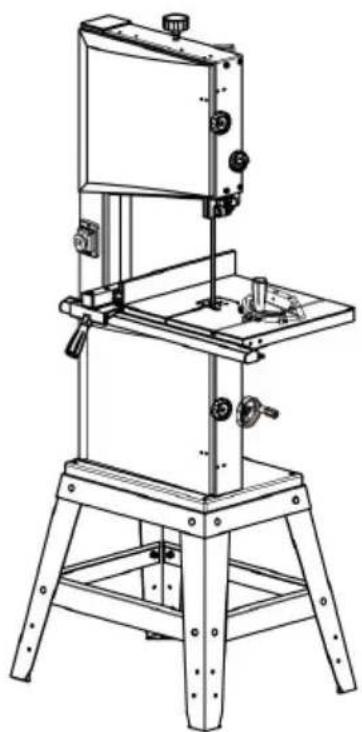
Line drawing of a mechanical device with a vertical frame and base mount (no text or symbols)NEED HELP? CONTACT US!
Have product questions? Need technical support? Please feel free contact us:
Technical Support and E-Warranty Certificate www.vevor.com/support
This is the original instruction, please read all manual instructions carefully before operating. VEVOR reserves a clear interpretation of user manual. The appearance of the product shall be subject to the product you received. Please forgive us that we won't inform you there are any technology or software updates on our product.
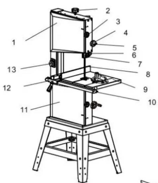
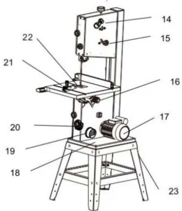
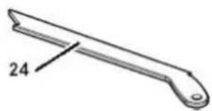
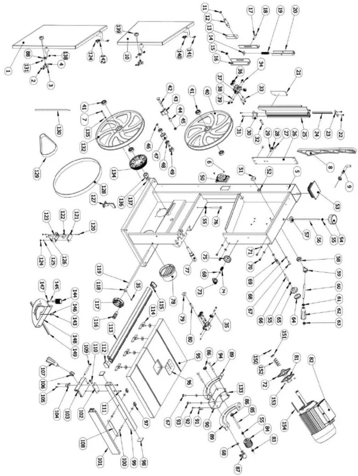
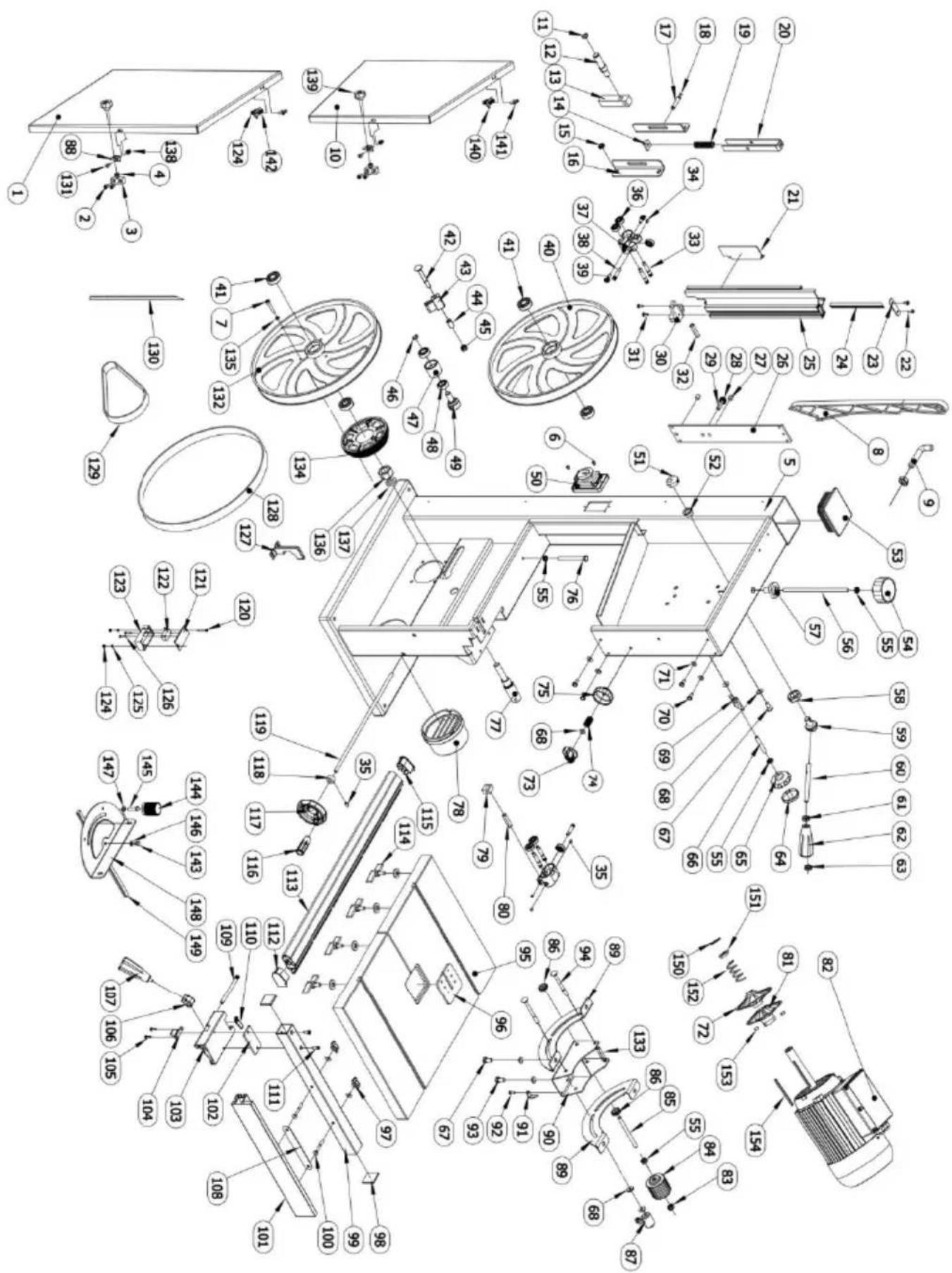
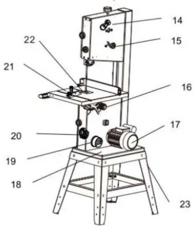
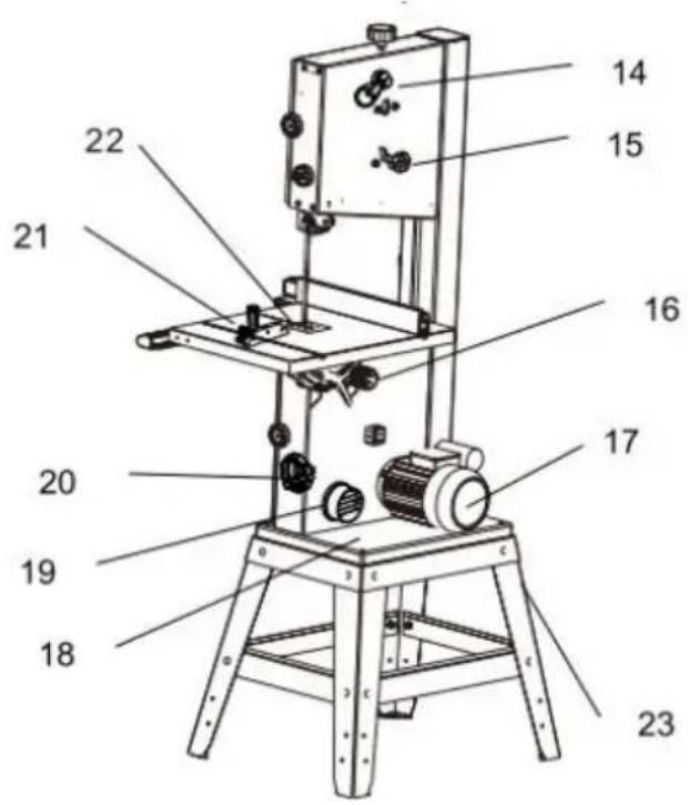
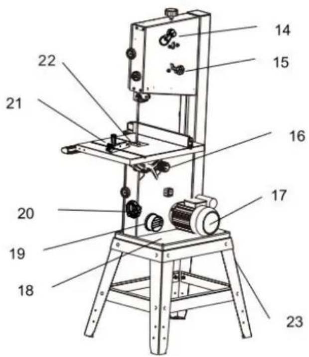
COMPONENTS AND PARTS(STANDARDDELIVERY)
natural_image
Simple line drawing of a tool or blade with a labeled dimension (24), no text or symbols present.| PART NO. | DESCRIPTION |
| 1 | Upper Housing Door |
| 2 | Setting Knob for Band Saw Blade Tension |
| 3 | Turn-Lock Fastener, Housing Door |
| 4 | Setting Knob for Blade Guard |
| 5 | Setting Knob for Locking Blade Guard |
| 6 | Blade Guard |
| 7 | Upper Blade Guide |
| 8 | Band Saw Blade |
| 9 | Saw Table |
| 10 | Fence Guide Extrusion, Graduated |
| 11 | Lower Housing Door |
| 12 | Rip Fence |
| 13 | On/Off Switch With Emergency Stop |
| 14 | Quick Release Lever for Band Saw Blade |
| 15 | Setting Knob for Blade Tracking Adjustment |
| 16 | Setting Knob for Table Turning Adjustment |
| 17 | Motor |
| 18 | Machine Base |
| 19 | Dust Extraction Port |
| 20 | Setting Knob for Drive Belt |
| 21 | Mitre |
| 22 | Table Insert |
| 23 | Stand Cabinet |
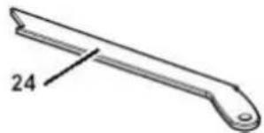
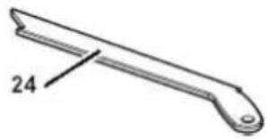
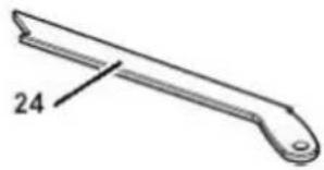
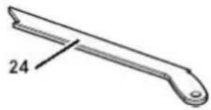
| 24 | Push Stick |
TABLE OF CONTENTS
PLEASE READ FIRST!
These operating instructions have been written to make it easier for you the user, to learn how to operate this machine and to do so safely. These instructions should be used as follows:
- Read these instructions before use. Pay special attention to the safety information.
- These operating instructions are intended for people with technical knowledge regarding the operation of a machine like this or similar electrical power tools. Inexperienced persons are strongly advised to seek competent advice and guidance from an experienced person before operating this machine.
- Keep all documents supplied with this machine for future reference. Retain your proof of purchase in case of a future warranty claim.
- This machine must not be sold or lent to someone else without being accompanied by all machine documents supplied with it.
- The manufacturer assumes no liability for any damage caused by neglect of these operating instructions.
Information in these instructions is marked as under:
 | Warning - To reduce the risk of injury, user must read instructions manual carefully. |
| ~ | Alternating current |
 | This symbol, placed before a safety comment, indicates a kind of precaution, warning, or danger. Ignoring this warning may lead to an accident. To reduce the risk of injury, fire, or electrocution, please always follow the recommendation shown below. |
 | Danger!Risk of personal injury or environmental damage! Risk of electric shock! Risk of personal injury by electric shock! |
 | Entanglement hazard! Risk of personal injury by body parts or clothin being drawn into the rotating saw blade. |
 | Caution! Risk of material damage. |
 | Note:Additional information. |
 | Warning- Be sure to wear ear protectors when using this product. |
 | Warning- Be sure to wear eye protectors when using this product. |
 | Warning- Be sure to wear gloves when using this product. |
 | This product is of protection class II. That means it is equipped with enhanced or double insulation. |
 | Disposal information: This product is subject to the provision of European Directive 2012/ 19/EC. The symbol showing a wheelie bin crossed through indicates that the product requires separate refuse collection in the European Union. This applies to the product and all accessories marked with this symbol. Products marked as such may not be discarded with normal domestic waste, but must be taken to collection point for recycling electrical and electronic devices |
SAFETY

WARNING: Read all safety warnings, instructions, illustrations and
specifications provided with this band saw.Failure to follow all instructions listed below may result in electric shock, fire and/or serious injury.
Save all warnings and instructions for future reference.

General Power Tool Safety Warnings-Work Area Safety
- Keep work area clean and well-lit. Cluttered or dark areas invite accidents.
- Do not operate power tools in explosive atmospheres, such as in the presence of flammable liquids, gases or dust. Power tools create sparks that may ignite dust or fumes.
- Keep children and bystanders away while operating a power tool. Distractions can cause you to lose control.

General Power Tool Safety Warnings-Electrical Safety
- Power tool plugs must match the outlet. Never modify the plug in any Do not use any adapter plugs with earthed(grounded)power tools.Unmodified plugs and matching outlets will reduce risk of electric shock.
- Avoid body contact with earthed or grounded surfaces, such as pipes, radiators, ranges and refrigerators. There is an increased risk of electric shock if your body is earthed or grounded.
- Do not expose power tools to rain or wet conditions. Water entering a power tool will increase the risk of electric shock.
- Do not abuse the cord. Never use the cord for carrying, pulling or unplugging the power tool. Keep cord away from heat, oil, sharp edges moving parts. Damaged or entangled cords increase the risk of electric shock.
- When operating a power tool outdoors, use an extension cord suitable for outdoor use. Use of a cord suitable for outdoor use reduces the rise of electric shock.
- If operating a power tool in a damp location is unavoidable, use a residual current device(RCD)protected supply. Use of an RCD reduces the risk of electric shock.

General Power Tool Safety Warnings-Personal Safety
- a) Stay alert, watch what you are doing and use common sense when operating a power tool. Do not use a power tool while you are tired under the influence of drugs, alcohol or medication. A moment of inattention while operating power tools may result in serious personal injury.
- Use personal protective equipment. Always wear eye protection.
Protective equipment such as a dust mask, non-skid safety shoes, har hat or hearing protection used for appropriate conditions will reduce personal injuries.
- Prevent unintentional starting. Ensure the switch is in the off-position before connecting to power source and/or battery pack, picking up or carrying the tool. Carrying power tools with your finger on the switch are energizing power tools that have the switch on invites accidents.
- Remove any adjusting key or wrench before turning the power tool on wrench or a key left attached to a rotating part of the power tool may result in personal injury.
- Do not overreach. Keep proper footing and balance at all times. This enables better control of the power tool in unexpected situations.
- Dress properly.Do not wear loose clothing or jewellery.Keep your hair and clothing away from moving parts.Loose clothes,jewellery or long hair can be caught in moving parts.
- If devices are provided for the connection of dust extraction and collection facilities, ensure these are connected and properly used. Use of dust collection can reduce dust-related hazards.
- Do not let familiarity gained from frequent use of tools allow you to become complacent and ignore tool safety principles. A careless action can cause severe injury within a fraction of a second.
Power Tool Use and Care
- a) Do not force the power tool. Use the correct power tool for your application. The correct power tool will do the job better and safer at rate for which it was designed.
-
Do not use the power tool if the switch does not turn on and off. An power tool that cannot be controlled with the switch is dangerous and must be repaired.
-
Disconnect the plug from the power source and/or remove the battery pack, if detachable, from the power tool before making any adjustments, changing accessories, or storing power tools. Such preventive safety measures reduce the risk of starting the power tool accidentally.
- Store idle power tools out of the reach of children and do not allow persons unfamiliar with the power tool or these instructions to operate the power tool. Power tools are dangerous in the hands of untrained users.
- Maintain power tools and accessories.Check for misalignment or binding of moving parts,breakage of parts and any other condition that may affect the power tools operation.If damaged,have the power tool repaired before use.Many accidents are caused by poorly maintained power tools.
- Keep cutting tools sharp and clean. Properly maintained cutting tools with sharp cutting edges are less likely to bind and are easier to con
- Use the power tool, accessories and tool bits etc. in accordance with these instructions, taking into account the working conditions and the work to be performed. Use of the power tool for operations different from those intended could result in a hazardous situation.
- Keep handles and grasping surfaces dry, clean and free from oil and grease. Slippery handles and grasping surfaces do not allow for safe handling and control of the tool in unexpected situations.
Service
- Have your power tool serviced by a qualified repair person using only identical replacement parts. This will ensure that the safety of the power tool is maintained.
1. Specified Conditions of Use
- The machine is suitable for cutting wood,wood-derived materials and plastics.Do not cut round stock transverse to its longitudinal axis without suitable jigs or fixtures.The rotating saw blade could turn the workpiece.When sawing thin stock lay on edge,a suitable guide must be used for firm support.
- Any other use is not as specified. The manufacturer is not liable for any damage caused by unspecified use.
- Alteration of the machine or use of parts not approved by the equipment manufacturer can cause unforeseeable damage!
2. General Safety Information
- When using this tool observe the following safety instructions, to exclude the risk of personal injury or material damage. Please also observe the special safety instructions in the respective chapters.
- Where applicable, follow the legal directives or regulations for the prevention of accidents pertaining to the use of band saws.

General hazards!
- Keep your work area tidy-a messy work area invites accidents. - Be alert.Know what you are doing.Set out to work with reason.Do not operate tool while under the influence of drugs,alcohol or medication. Consider environmental conditions:keep work area well-lighted.
● Prevent adverse body positions. Ensure firm footing and keep your balance at all times. When working long stock use suitable supports.
- Do not operate tool near inflammable liquids or gases.
- The saw shall only be started and operated by persons familiar with band saws and who are at any time aware of the dangers associated with the operation of such tool.
- Keep bystanders, particularly children, out of the danger zone. Persons under 18 years of age shall use this tool only in the course of their vocational training, under the supervision of an instructor.
- Do not permit other persons to touch the tool or power cable while it is running.
- Do not overload tool "C use it only within the performance range it was designed for(see"Technical specifications").

Danger!Risk of Electric Shock!
- Do not expose tool to rain.
- Do not operate tool in damp or wet environment.
● Prevent body contact with earthed objects such as radiators, pipes, cooking stoves, refrigerators when operating this tool.
- Do not use the power cable for any purpose it is not intended for.

Risk of personal injury and crushing by moving parts!
- Do not operate the tool without installed guards.
● Always keep a sufficient distance from the band saw blade. Use suitable feeding aids if necessary.
- Keep sufficient distance to drive components when operating this tool. Do not attempt to stop the band saw blade by pushing the workpiece against its side.
- Ensure tool is disconnected from power supply before servicing. Ensure that when switching on(e.g.after servicing)no tools or loose parts are left on or in the tool.
● Turn power off if the tool is not used.

Cutting hazard, even with the cutting tool at a standstill!
Wear gloves when changing cutting tools.

Risk of kickback(workpiece is caught by the band saw blade
and thrown against the operator)!
- Do not jam workpieces.
- Cut thin or thin-walled workpieces only with fine-toothed saw blades. Always use sharp band saw blades.
- If in doubt, check workpiece for inclusion of foreign matter(e.g. nails or screws).
- Cut only stock of dimensions that allow for safe and secure holding which cutting. Never cut several workpieces at the same time and also no bundles containing several individual pieces. Risk of personal injury if individual pieces are caught by the band saw blade uncontrolled.
- When cutting round stock, use a suitable jig to prevent the workpiece from turning.

Entanglement hazard!
Ensure that no parts of the body or clothing can be caught and drawn in rotating components(no neckties,no loose fitting clothes;contain long hair with hairnet).
Never cut workpieces containing the following materials:
-Ropes
-Strings
-Cords
-Cables
-Wires

Hazard generated by insufficient personal protection gear!
- Wear hearing protection.
- Wear safety glasses.
- Wear dust mask.
● Wear suitable work clothes. - When working outdoors, wearing non-slip shoes is recommended.

Risk of injury by inhaling wood dust!
Dust of certain timber species(e.g.oak,beech,ash)can cause cancer when inhaled:work only with a suitable dust collector connected to the saw.

Hazard generated by modification of the machine, or use of
parts not tested and approved by the equipment manufacturer!
Assemble tool in strict accordance with these instructions. Use only parts approved by the equipment manufacturer. Use only tools (band saw blades) conforming to EN 847-1:1997.
Do not change any parts.

Hazard generated by tool defects!
- Keep tool and accessories in good repair. Observe the maintenance instructions. Check tool for possible damage prior to any use:
- Before operating the tool all safety devices, protection devices or slightly damaged parts must be inspected for proper functioning as specified.
- Check to see that all moving parts work properly and do not jam. All pa must be correctly installed and meet all conditions necessary for the proper operation of the tool.
- Damaged protection devices or parts must be repaired or replaced by a qualified specialist. Have damaged switches replaced by a service centre. Do not operate tool if the switch cannot be turned ON or OFF. Keep handles free of oil and grease.
3. Symbols on the Machine

Danger! Disregard the following warnings may lead to serious personal injury or material damage.

Read instructions.

Band saw blade running direction.
4. Safety Devices
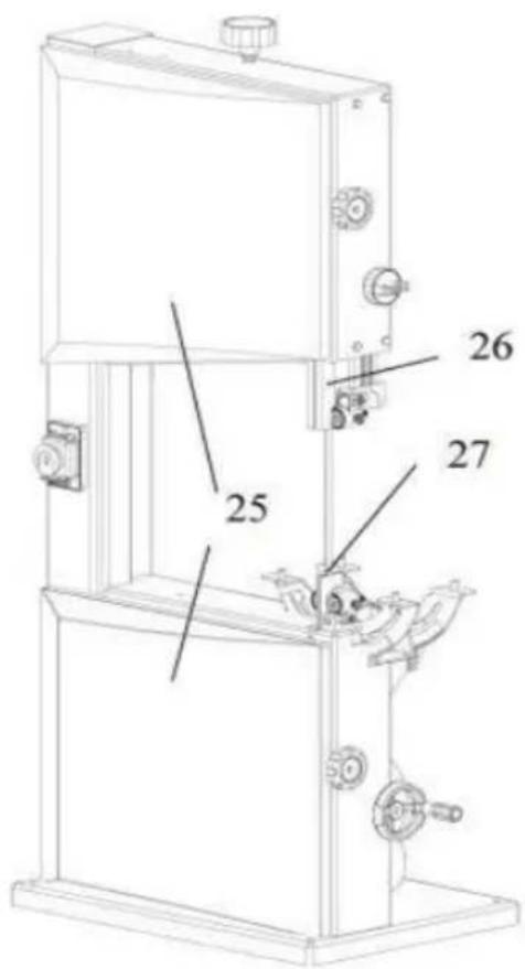
Upper Blade Guard
- The upper blade guard(26)protects against unintentional contact with the saw blade and from chips flying about. In order for the upper blade guide to provide adequate protection against contact with the band saw blade, it must always be set as close as possible to the workpiece (max.distance 3 mm).
Lower Blade Guard
- The lower blade guard(27) protects against unintentional contact with the saw blade.
- The lower blade guard must always be in place and cover the band saw blade while the band saw is running.
Housing Doors
- The housing doors(25)protect against contact with the rotating parts inside the machine. Both housing doors must be closed while the machine is in use.
Push Stick
- The push stick serves as an extension of the hand and protects against accidental contact with the saw blade.
- The push stick must always be used if the distance between band sa blade and a rip fence is less than 120 mm. Guide the push stick at a angle of 20^ 30^ against the saw table's surface.
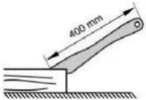
- When the push stick is not used it can be stored on the push stick holder provided at the band saw frame. Replace push stick if damaged
TRANSPORT
● Set upper blade guide to its lowest position.
- Remove projecting accessories.
- When shipping, use original packing if possible.
MACHINE DETAILS
Final Assembly and Installation.
Unpack machine and check for any visible damage which may have occurred during transport. If a damage is detected notify your dealer immediately.
This machine is shipped partly disassembled. Saw table and rip fence guide have to be installed prior to use.
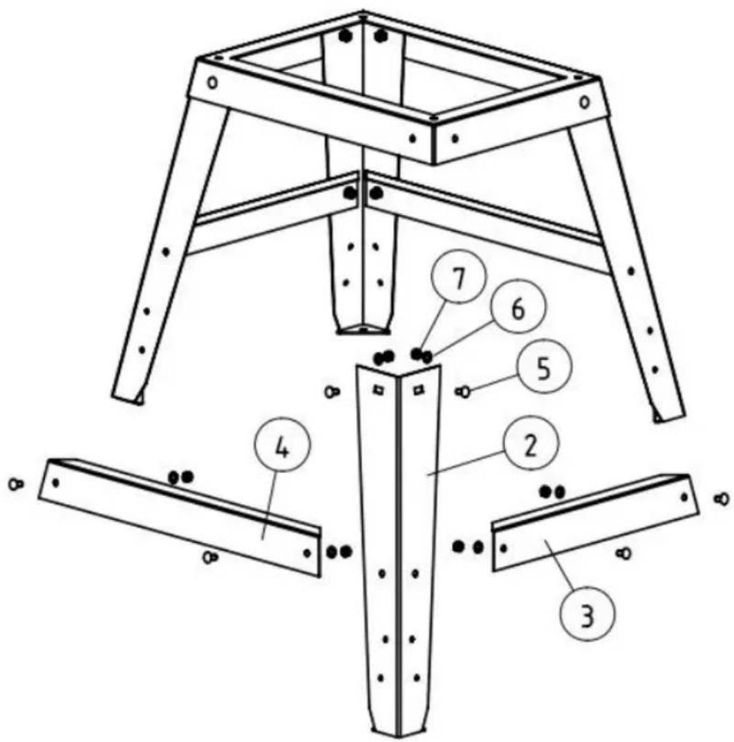
Stand accessories
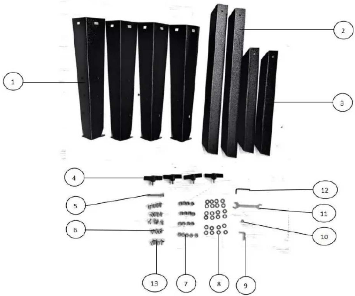
| PART NO. | DESCRIPTION | QTY |
| 1 | Leg | 4 |
| 2 | Long connecting plate | 2 |
| 3 | Short connecting plate | 2 |
| 4 | Thumb Screw | 4 |
| 5 | Screw M8×55 | 1 |
| 6 | carriage bolt M8×16 | 16 |
| 7 | Hexagon nut M8 | 17 |
| 8 | Flat washer 8 | 24 |
| 9 | “L” screw | 1 |
| 10 | Hexagon nut M6 | 1 |
| 11 | Wrench | 1 |
| 12 | Allen Wrench SW 3 | 1 |
| 13 | Screw M8×16 | 4 |
Assembly
| Fit Leg (1) to the Base with carriage bolt M8×16(6), 8Flat Washer 8 (8) and 8 Hex.Nut M8(7). | 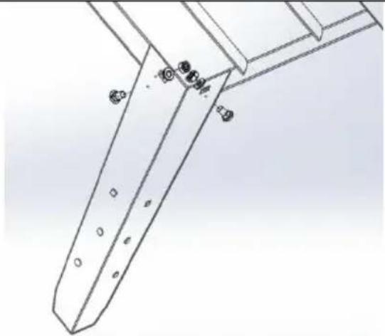 |
| Fit Long connecting plate (2) and Short connecting plate (3) to Leg(1) with 8 carriage bolt M8×16(6), 8Flat Washer 8 (8) and 8 Hex.Nut M8(7). | 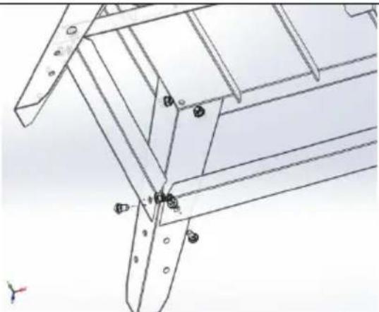 |
| Installing the Saw Table1. Fit limit stop screw M8×55(5) and Hex.Nut M8(7) to the underside of low house.2. Guide saw table over the band saw blade and place it on the table trunnion.3. Attach the saw table with four Screw M8×16(13)and washers 8 to(8 the table trunnion. | 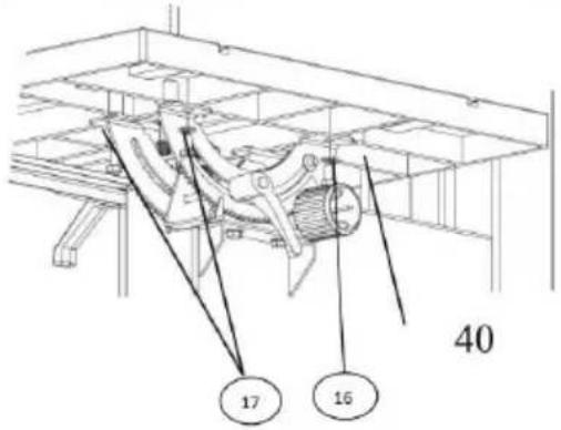 |
| Installing the Fence Guide ExtrusionFasten the fence guide extrusion(43)with four thumb screws and washers to the saw table. | 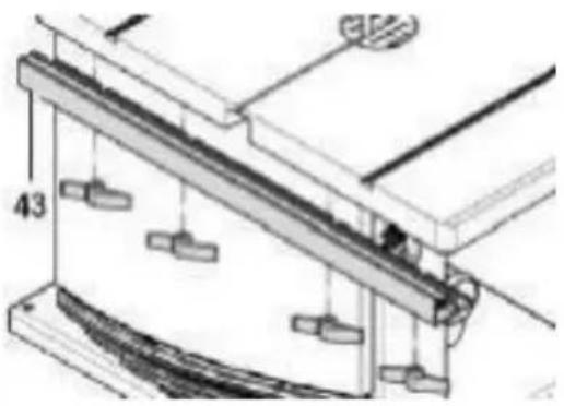 |
| Adjust the flatness of the tableAdjust by controlling the position of the Hex Bolt (1,2) on the fence. | 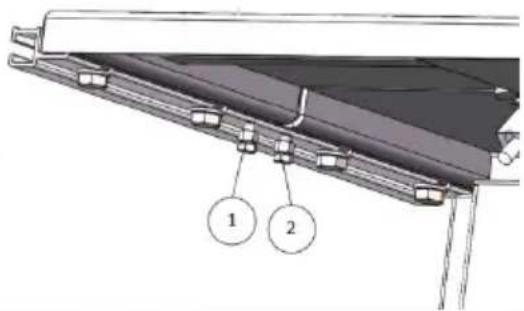 |
| Rip Fence:The rip fence(37)clamps to the front of the bandsaw table;The fence can be used on both sides of blade.Mitre Fence:The mitre fence is inserted into the table slot from the table's front edge.For mitre cuts the mitre fence turns to60°in both directions For 45°and 90°miters positive stops are provided.To set a mitre angle:loosen lock handle(38)by turning it counter-clockwise.When cutting with the mitre fence lock handle must be firmly tightened | 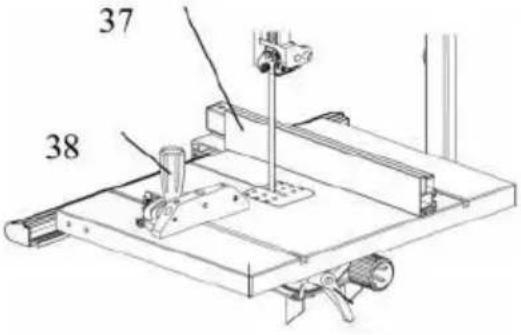 |
| Installing the Push Stick HolderTurn a hexagon nut on a cap screw, the way up to the unthreaded part the shank.Turn cap screw into the hole on the left side of the band saw.Tighten hexagon nut hand-tight only Hang push stick on the cap screw when not in use. | 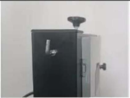 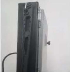 |

Note: In this chapter, the essential operating elements of the machine are introduced.
The proper use of the machine is described in chapter"Operation".Read this chapter before using the saw for the first time.
| ON/OFF Switch with Emergency Stop1. To start=press the green switch button(29).2. To stop=press the red switch button(28)or the cover(30)of the ON/OFF switch.3. In the event of a voltage failure an undervoltage relay trips.This prevents the machine from starting when the power is restored.To restart,the green switch button must be pressed.4. the machine from starting up when the power is restored.To restart,the green switch button must be pressed. | 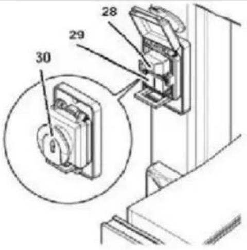 |
| Setting Knob for Band Saw Blade T1. With the setting knob(31)the band saw blade tension is corrected,if necessary:2. Turning the setting knob clockwise increases the blade tension.3. Turning the setting knob counterclockwise reduces the blade tension. | 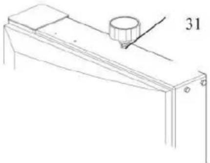 |
| Quick Release LeverWith the quick release lever(32)the saw blade tension is released. | 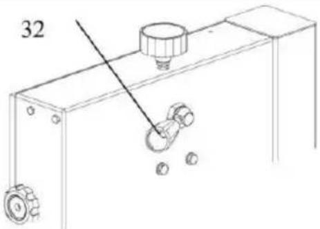 |
| Setting Knob for Blade Tracking Adjustment1. With the setting knob(33)the tilt of the upper band saw wheel can be adjuste necessary.This tracking adjustment is required to have the blade run dead center on the rubber tyres of the ban saw wheels.2. Turning clockwise=blade moves to the rear.3. Turning counter-clockwise=blademoves to the front. | 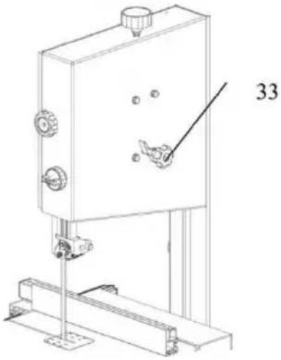 |
| Speed AdjustmentAdjust the hand wheel to adjust the speed the band saw:low speed for hard wood,plastics.high speed for all kinds of wood.With the setting knob(34)the drive belt tension is corrected,if necessaryTurning the setting knob counterclockwise increases the blade tension.Turning the setting knob clockwise reduces the blade tension. | 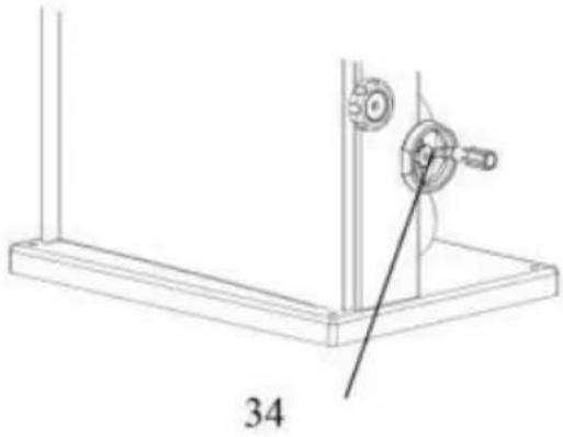 |
| Saw Table TiltAfter loosening the lock screw(35)the saw table(36)tilts steplessly through 45°against the blade. | 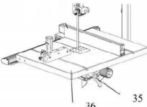 |
| Installing the Rip FenceThe rip fence can be used on both s of the blade.When the rip fence is moved from one side of the saw blad the other the fence extrusion(44)needs be reversed.Place rip fence on the rip fence guide.Tighten the lock lever(45)of the rip. | 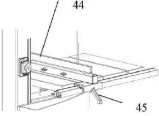 |

Danger!Start the saw only after the following preparations are
completed:
-The saw is securely mounted;
-The saw table is installed and aligned;
-The V-belt tension was checked;
-Safety devices have been checked. Connect the saw to the mains supply only after all of the above preparations are completed! Otherwise there is a risk of an unintentional starting of the saw, which can cause severe personal injury.
1. Mounting
For a firm stand the saw must be mounted on a stable supporting surface
- Drill 4 holes in the supporting surface.
- Put fixing bolts through the base plate and secure it with nuts.
- Optimal working height and stability are provided by the steel stand, which is already prepared for mounting the saw. Information regarding the assembly of the stand is given in the addendum to these operating instructions.
2. Aligning the Saw Table
The saw table needs to be aligned in two planes
-Laterally, in order for the blade to run dead centre through the table insert;
-At right angles to the band saw blade.
Saw Table Lateral Alignment
- Loosen the four fastening screws that hold the lower support of table trunnion.
- Align the working table so that the blade runs through the centre of the table insert's slot.
● Tighten the four fastening screws again.
natural_image
Mechanical assembly diagram showing a cutting tool interacting with a base plate and circular components (no text or symbols)Aligning the Working Table at Right Angles to the Band Saw Black
- Raise upper blade guide fully. Check band saw blade tension.
- Loosen the lock lever.
- Using a try square, set the table at right angles to the blade and tighter the lock lever again.
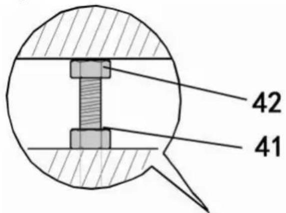
- Loosen locking nut(41)and adjust limit stop screw(42)until it touches the working table.
● Tighten the locking nut.
3. Dust Collector Connection

Danger! Dust of certain timber species(e.g.oak,beech,and ash) can cause cancer when inhaled: always use a dust collector with working in enclosed spaces (air speed at the saw's dust extraction port ≥ 20 m/s).

Caution!Operation without a dust collector is only possible:
- Outdoors;
- For short-term operation(up to max.30 minutes);
● With dust respirator. - If no dust collector is used chips will accumulate, which need to be removed periodically.
Connect dust collector or industrial vacuum with a suitable adaptor to the dust extraction port.
4. Tensioning the Band Saw Blade

Danger! Too much tension can cause the band saw blade to
break. Too little tension can cause the driven band saw wheel to stand and the band saw blade to stop.
- Raise upper blade guide fully.
- Checking the blade tension:-Check tension by pushing with a finger,halfway between table and upper blade guide,against the side of the blade(the blade should flex not more than 1-2 mm).
- Check adjustment at the blade tension indicator. The scale indicate correct adjustment in dependence on the band saw blade width.
- Correct tension if necessary: turning the setting knob(48) counterclockwise increases the blade tension. Turning the setting knob(48) counter-clockwise reduces the blade tension.

5. Connection to Power Mains

Danger!High Voltage Operate the saw only in a dry
environment.
Operate the saw only on a power source matching the following requirements:
● Mains voltage and system frequency conform to the voltage and frequency shown on the machine's nameplate;
● Fuse protection by a residual current operated device(RCD)of 30 mA sensitivity;
● Outlets properly installed, earthed and tested;

Note:
Check with your local Electricity Board or your electrician if in doubt whether your house service connection meets the requirements.
- Make sure the power supply cable is out of the way, so that it does not interfere with the work and does not pose a tripping hazard or will get damaged.
- Protect the power supply cable from heat, aggressive liquids and sharp edges.
● Use only rubber-insulated extension cables of sufficient lead cross
● section(3 x 1.5 mm2, for machines with 3-phase motor: 5 x 1.5 mm2). - Do not pull on the power supply cable to unplug.
a. When the saw is assembled and all safety devices are installed, connect it to the power supply.
b. Start saw briefly and turn OFF immediately again.
c. Check the band saw blade's direction of rotation: in the cutting area it must run from the top downwards.
d. If the band saw blade turns in the wrong direction, unplug the power supply cable at the saw.
e. Have the electrical connection changed by a qualified electrician!
6. Connection to Power Mains
Assembly the cabinet stand
- Check contents against the parts list.
- Locate back panel and right&left end panels onto the base panel,secure using hex bolts and washers.
- Fasten the right&left end panels to the back panel,secure using hex bolts and washers.
- Fasten the front bracing member onto the right&left end panels assemble using hex bolts and washers.Fasten the shelf on the right&left end panels using remaining hex bolts and washers.
● Fit the door onto the end panel. - With assistance, lift the band saw and carefully position it in place on top of the work-stand.
- Fix in position using hex bolts, through washer, cabinet stand, washer, hex nut, band saw and lock-8-washer then secure on upper side with hex nut. Repeat procedure for all four corners before tightening fully.
OPERATION

Danger! To reduce the risk of personal injury as much as le, the following safety recommendations should be observed operating the saw.
Use personal protection gear:
- Dust respirator;
● Hearing protection; - Safety goggles.
Cut only one workpiece at a time.
Always hold the workpiece down on the table.
Do not jam the workpiece.
Do not attempt to stop the band saw blade by pushing the workpiece against its side.
If the type of work requires, use the following:
● Work support for long stock, which would otherwise fall off the table on completion of the cut;
- Push stick-if distance rip fence-band saw blade d120 mm;
- Dust collector;
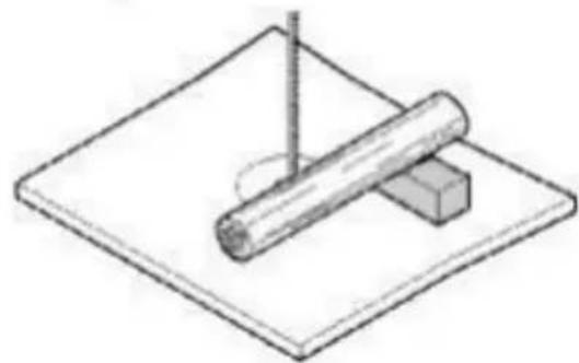
● An appropriate jig when cutting round stock, to keep it from turning;
natural_image
Simple line drawing of a cylindrical object resting on a rectangular block on a flat surface (no text or symbols)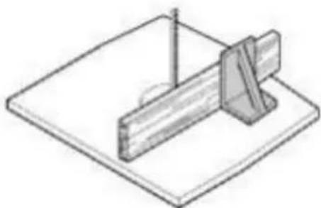
natural_image
Isometric line drawing of a mechanical setup with a rod and bracket on a flat base (no text or symbols)● A suitable guide for firm support when cutting thin stock lay on edge.
- Before starting work, check to see that the following are in proper working order:
- Bandsaw blade;
● Upper and lower blade guard.
- Replace damaged parts at once!
- Assume correct work position(the band saw blade's teeth must point towards the operator).
- Never cut several workpieces at the same time, and also, any bundles containing several individual pieces. Risk of personal injury if individual pieces are caught by the saw blade uncontrolled

Drawing-in/trapping hazard!
- Do not wear loose clothing, jewellery, or gloves, which may get caught and wound up by revolving machine parts.
- Contain long hair with a hairnet.
- Never cut stock to which ropes, cords, strings, cables and wires are attached or which contain such materials.
Upper blade guide adjustment
The height of the upper blade guide (50) needs to be adjusted:
- Prior to every cutting operation, to accommodate the height of the workpiece (the upper blade guide should be set approx. 3 mm above the workpiece);
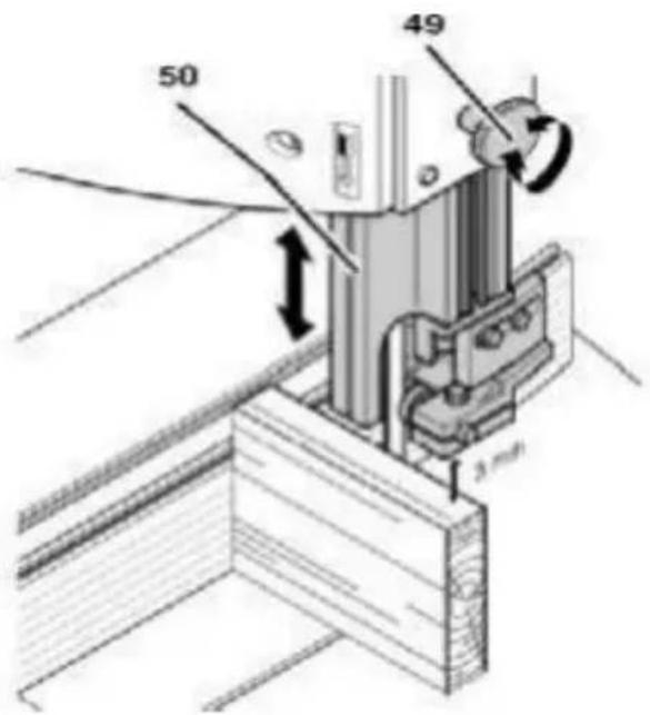
- After adjustments of band saw blade or saw table(e.g.band saw blade change,tensioning of the band saw blade,saw table alignment).

Danger!Before adjusting the upper blade guide and saw table
tilt:
- Switch machine OFF.
- Wait until the band saw blade has come to a complete stop. Set upper blade guide(50) with the adjusting knob(49) to the desired
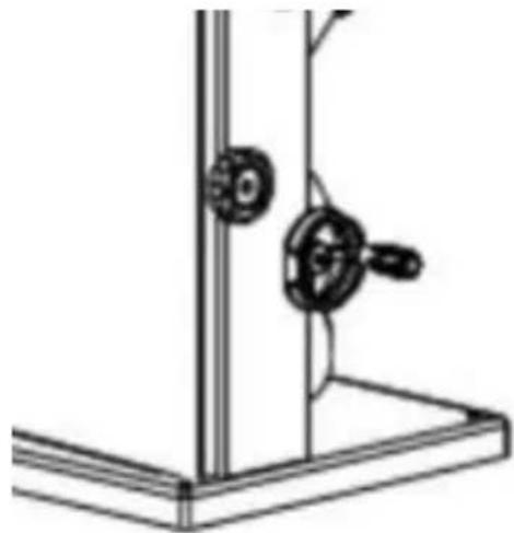
Cutting Speed Adjustment
-
Adjust the hand wheel to adjust the speed of the band saw. 2. Clockwise rotation speed increased.
-
Counterclockwise rotation speed decreases.
-
Speed range:
50Hz:500-880m/min
60Hz:600-1050m/min
natural_image
Technical line drawing of a mechanical assembly with two circular components mounted on a vertical frame (no text or symbols)1. Sawing
1) Choose and install a table insert extrusion suitable for the type of cut be performed:
● Table insert extrusion with a narrow slot for standard cross-cuts only;
● Table inserts extrusion with a beveled slot for bevel cuts also.
2) Adjust the band saw blade speed.
3) If necessary, adjust the table tilt.

Risk of kickback(workpiece is caught by the band saw blade and thrown against the operator)! Do not jam any workpieces.
4) Select rip fence and table tilt for the type of cutting operation to be carried out.
5) Set upper blade guide 3 mm above the workpiece.

Note:Always make a trial cut in a piece of scrap to verify settings;correct if necessary before cutting the workpiece.
6) Place workpiece on the saw table.
7) Plug in.
8) Start saw.
9) Cut workpiece in a single pass.
10) Switch off if no further cutting is to be done immediately afterwards.
CAREAND MAINTENANCE

Danger!Prior to all servicing:
- Switch machine OFF.
- Unplug power cable.
● Wait until the saw has come to a complete stop. - Check that all safety devices are operational again after each service.
- Replace defective parts, especially safety devices, only with genuine replacement parts. Parts not tested and approved by the equipment manufacturer can cause unforeseen damage.
● Repair and maintenance work other than described in this section should only be carried out by qualified specialists.
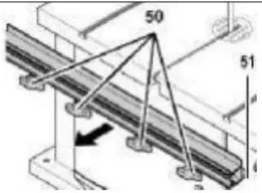
- Changing and Setting the Saw Blade.
Risk of injury, even with the band saw blade at a standstill. Wear gloves when changing blades. Use only suitable band saw blades.
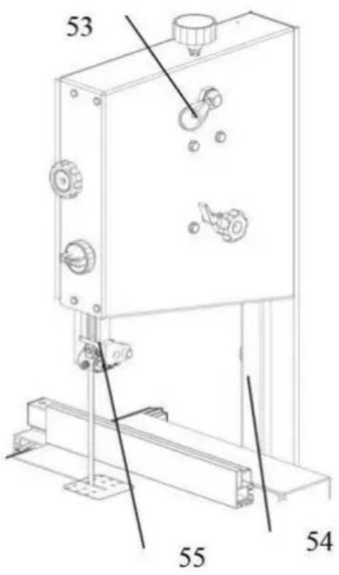
- Loosen the four screws(50)and remove the fence guide extrusion(51).
- Open both housing doors.
- Set the upper blade guide(55)to its lowest position.
- Then slacken the blade tension by turning the handwheel(48) of top of the upper wheel housing Remove the blade guide it
through
● The slot in the saw table
● The blade guard on the upper blade guide
● The blade cover on the saw housing(54)and The blade guides.
-
Fit a fresh band saw blade. Observe correct position: the teeth point towards the front (door) side of the saw.
-
Center band saw blade on the rubber tyres of the band saw wheels.
-
Tighten quick release lever until blade no longer slip off the ba saw wheels.
-
Close both housing doors.
-
Then:
-
Tension band saw blade(see"Initial operation").
- Align band saw blade(see"Care and maintenance");
- Align blade guides(see"Care and maintenance");
- Let saw test run for at least on minute;
- Stop saw,unplug and recheck settings.
| Aligning the Band Saw BladeIf the band saw blade does not ruthe centre of the rubber tyres,the tracking needs to be corrected by adjusting the tilt of the upper band saw wheel:Loosen lock nut(56).Turn setting knob(57):-Turn setting knob(57)clockwise if the band saw blade runs towards front of the saw.-Turn setting knob (57) counter clo wise if the band saw blade runstowards the rear of the saw.Tighten lock nut(56). | 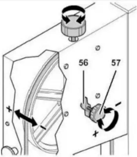 |
| Aligning the Upper Blade GuideThe upper blade guide consists of:Athrust bearing(supporting the band saw blade from the rear)Two guide bearings(providing lateral support).All bearings need to be readjusted after every band saw blade change and/or tracking adjustment.Periodically check all bearings for wear. If necessary, replace both guide bearings at the same time. | |
| Adjusting the Thrust Bearing1. If necessary, align and tighten the band saw blade.2. Loosen fixing screw of the upp blade guide.3. Align upper blade guide4. Tighten the upper blade guide's fixing screw.5. Loosen the thrust bearing's lock screw.6. Adjust thrust bearing position(distance thrust bearing-band sawblade=0.5 mm-if the band saw blade is turned by hand, it must not touch the thru bearing).7. Tighten the thrust bearing lock screw. | 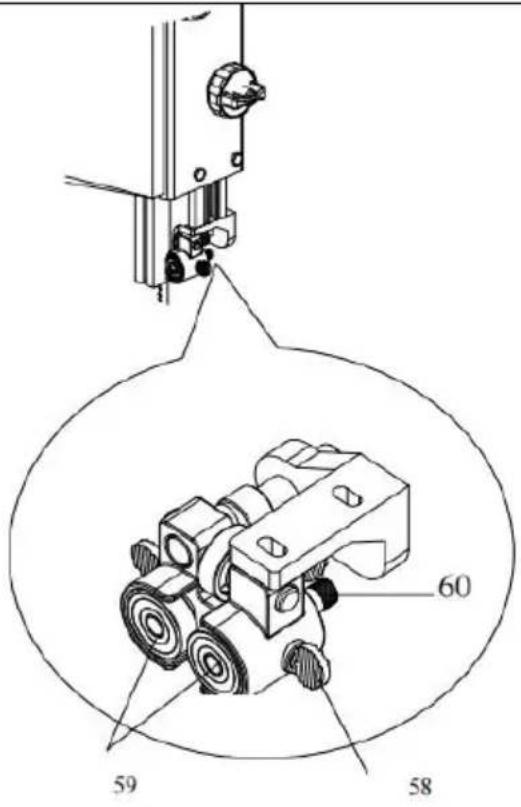 |
| Adjusting the Guide Bearings1. Loosen locking bolt(58).2. Set guide bearings(59)with the shaft(60)against the band saw blade.3. Turn band saw wheel by har in a clockwise direction several times to bring the guide bearings in correct position-both guide bearings should just touch the band saw.Retigthen locking bolt(58)to lock the shaft(60) | |
| Aligning the Lower Blade GuideThe lower blade guide consists of: | |
| ● Athrust bearing(supporting the band saw blade from the rear)Two guide bearings(providing lateralThese parts need to be readjusted after every band sawblade change or tracking | |
| Replacing the Band Saw TyrePeriodically check band saw tyres for wear.Replace only in pairs:1. Remove band saw blade(see"Care and Maintenance");2. Lift band saw tyre with a small screwdriver,then pull off the band saw wheel.3. Mount new band saw tyres and reinstall the band saw blade. | 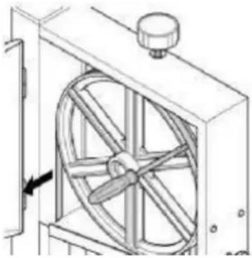 |
| Replacing the Table InsertThe table insert needs replacement when its slot has become enlarged or damaged.1. Remove table insert(61)from saw table(push up from underneath).2. Fit new table insert. | 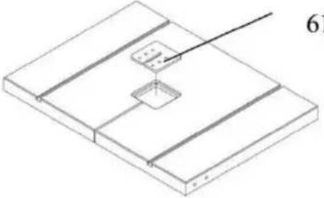 |
| Cleaning the Saw1. Open the housing doors.2. Remove chips and sawdust with brush or vacuum cleaner.3. Close the housing doors | |
| Store saw whereIt cannot be used or tampered with by unauthorized persons aNobody can get hurt by the machine.Do not store the saw outdoors, in unprotected areas or in damp wet locations. | |
| Belt Replacement1.Turn the handwheel and loosen belt.2.Loosen the quick rise at the bac the band saw and loosen the saw blade.3.Loosen the spring with a spring clamp. | 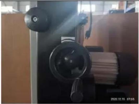 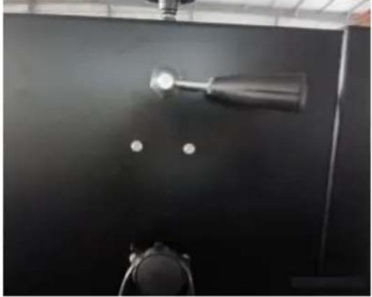 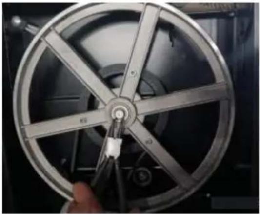 |
- Take off the lower wheel and replace the belt

natural_image
Close-up of a hand holding a metallic wheel with visible spokes and a circular head (no text or symbols)
Danger!
Repairs to electric tools must be carried out by qualified electricians. Electric tools in need of repair can be sent to the service center of country. Refer to the spare parts list for the address.
Please attach a description of the fault to the electric tool.
ENVIRONMENTAL PROTECTION
All packaging materials are 100% recyclable. Worn out power tools an accessories contain considerable amounts of valuable raw and rubber materials, which can be recycled.
These instructions are printed on paper produced with elemental chlorine-free bleaching process.
TROUBLE SHOOTING

Danger!
Before carrying out any fault service or maintenance work always:
- Switch machine OFF
- Unplug power cable.
● Wait until the band saw blade has come to a complete stop.
Check to see that all safety devices are operational after each fault service
Motor does not run
Under voltage relay tripped by power failure:
- Switch on again.
- No mains voltage
- Check cables, plug, outlet and mains fuse.
- Motor overheated, e.g. by a blunt band saw blade or chip build-up in th housing:
- Remove cause for overheating, let cool down for a few minutes, then start again.
Band saw blade wanders off the line of cut or runs off the k wheels
Band saw blade is not running dead center on the band saw wheels:
- Correct tracking(see"Care and maintenance").
Band saw blade breaks
Incorrect tension:
- Correct band saw blade tension(see"Initial operation"). Load too high:
Reduce pressure against band saw blade(reduced feed speed). Incorrect band saw blade:
- Replace band saw blade(see"Care and maintenance"): Thin stock=narrow band saw blade Thick stock=wide band saw blade.
Band saw blade warped
Load too high:
● Avoid lateral pressure on the band saw blade.
Saw vibrates
- Insufficient mounting:
- Fasten saw properly to a suitable surface(see"Initial operation"). Saw table loose:
- Align and fasten saw table.
Motor mount loose:
- Check fastening screws, tighten if necessary.
Dust extraction port blocked
No dust collector connected or suction capacity insufficient:
- Connect a dust collector or increase suction capacity(air speed≥20 m/sec at dust extraction port).
TECHNICAL SPECIFICATIONS
| POWER | 1100W |
| Max. Throat width | 340mm |
| Max.cutting height | 330mm |
| Sawblade lenght | 2780mm |
| Sawtable size | 400*548mm |
| Max.Sawblade speeds(50Hz) | 880m/min |
| Max.Sawblade speeds(60Hz) | 1050m/min |
| NW | 81.8KG |
| GW | 105KG |
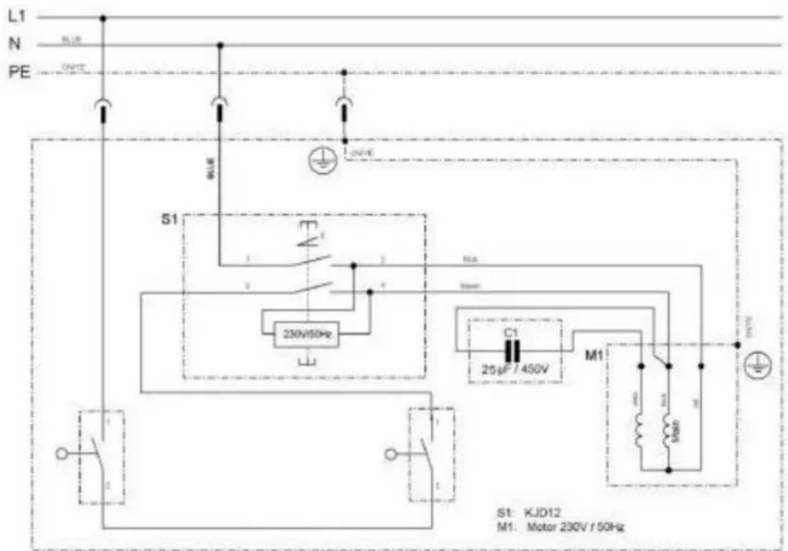
ELECTRICALWIRING DIAGRAM
Band Saw Cabinet Stand
| ITEM | PART NO. | NAME | Q'ty |
| 2 | DJ350A01202 | Leg | 4 |
| 3 | DJ350A01204 | Short connecting plate | 2 |
| 4 | DJ350A01203 | Long connecting plate | 2 |
| 5 | GB/T801 M8×16 | carriage bolt | 16 |
| 6 | GB/T97.1 8 | Flat washer | 16 |
| 7 | GB/T6170/1 M8 | Hexagon nut | 16 |
| ITEM | PART NO. | NAME | Q'ty |
| 1 | DJ350A04100W | Lower Door | 1 |
| 2 | GB70-85 M5×10 | Hex. Socket Set Columned Head Bolt | 4 |
| 3 | DJ31505008 | Fixed Block | 2 |
| 4 | GB889-86 M6 | Locking Nut | 2 |
| 5 | BS35000000P | Band Saw Frame | 1 |
| 6 | M4×12 | Countersunk head screws | 2 |
| 7 | GB70-85 M6×25 | Hex. Socket Set Columned Head Bolt | 6 |
| 8 | TJ315B06012A | Push Stick | 1 |
| 9 | DJ200030904 | Hook | 1 |
| 10 | DJ350A03100 | Upper Door | 1 |
| 11 | GB894.1-86 15 | Circlip for Shaft | 2 |
| 12 | DJ350A03006 | Bearing Bolt Upper | 1 |
| 13 | DJ38003003 | Bearing Bolt Support Upper | 1 |
| 14 | DJ250A03009 | Nut | 1 |
| 15 | GB6177-86 M8 | Hex. Flanged Nut | 4 |
| 16 | DJ350A03008 | Guiding Plate | 2 |
| 17 | DJ250A03007 | Shaft | 1 |
| 18 | GB896-86 6 | Split Washer | 2 |
| 19 | DJ315S03015 | Spring | 1 |
| 20 | DJ250A03010 | Tension Bracket Frame | 1 |
| 21 | DJ350A03005 | Slider | 1 |
| 22 | GB845-85ST4.8× 16 | Cross Recessed Pan Head Tapping Screw | 2 |
| 23 | 31503034 | Cover Board | 1 |
| 24 | 31503038 | Rack | 1 |
| 25 | DJ350A03001 | Guide Carrier Extrusion | 1 |
| 26 | DJ350A03003 | Pressure Plate | 1 |
| 27 | GB70-85 M5×6 | Hex. Socket Set Columned Head Bolt | 2 |
| 28 | DJ31703113 | Gear | 1 |
| 29 | DJ350A03007 | Shaft for Gear | 1 |
| 30 | 31503014B | Guide Carrier System | 1 |
| 31 | GB845-85 ST4.8×22 | Cross Recessed Pan Head Tapping Screw | 2 |
| 32 | DJ350A03009 | Fixed rod | 1 |
| 33 | DJ315S03012A-2 | Guiding Shaft | 4 |
| 34 | GB77-85 M6×12 | Hex. Socket Set Screw | 1 |
| 35 | GB77-85 M6×8 | Hex. Socket Set Screw | 6 |
| 36 | GB/T278-89 80027 | Bearing | 6 |
| 37 | DJ315S03012A | Three Roller Guide Housing | 2 |
| 38 | DJ315S03012A-3 | Shaft For Pilot | 2 |
| 39 | 31504018 | Setting Knob for Locking | 2 |
| 40 | DJ350A04008 | Upper Wheel | 1 |
| 41 | GB/T276-94 6202-2Z | Bearing | 4 |
| 42 | GB14-88 M8×100 | Cup Head Square Neck Bolt | 1 |
| 43 | 31504015 | Brush Strip | 1 |
| 44 | 31504014 | Spacer Bushing | 1 |
| 45 | GB6177-86 M8 | Hex. Flanged Nut | 1 |
| 46 | GB894.1-86 12 | Circlip for Shaft | 1 |
| 47 | 31504012 | Tension Wheel | 1 |
| 48 | GB/T278-89 6001-2Z | Ball Bearing | 2 |
| 49 | 31504013 | Sliding Shaft | 1 |
| 50 | CK-5 | Switch | 1 |
| 51 | DJ31703008 | Cam | 1 |
| 52 | DJ31703009 | Spacer Bushing | 1 |
| 53 | DJ350A05002 | Lamello Plug | 1 |
| 54 | 31503006 | Setting Knob | 1 |
| 55 | GB6172-86 M8 | Hex. Thin Nut | 2 |
| 56 | DJ38003004-01 | Thread Bolt | 1 |
| 57 | DJ38003002 | Tension Pan | 1 |
| 58 | GB6173-86 M20× 1.5 | Hex. Nut | 1 |
| 59 | DJ31703010 | Seat for Quick Release Shaft | 1 |
| 60 | DJ38003007 | Quick Release Shaft | 1 |
| 61 | GB6172-86 M10 | Hex. Thin Nut | 1 |
| 62 | TJ315B03002-1 | Locking Handle | 1 |
| 63 | GB6170-86 M10 | Hex. Nut | 1 |
| 64 | 31503008-2 | Setting Knob | 1 |
| 65 | 31503008-1 | Cap | 1 |
| 66 | GB5783-86 M8x45 | Hex. Bolt | 1 |
| 67 | GB5783-86 M8x 16 | Hex. Bolt | 8 |
| 68 | GB97.1-85 8 | Washer | 16 |
| 69 | 31503007 | Wing Nut | 5 |
| 70 | GB5783-86 M6X10 | Hex. Bolt | 4 |
| 71 | GB97.1-85 6 | Washer | 38 |
| 72 | RWL1000F0217 | Pulley motor(right) | 1 |
| 73 | DT/SB030 | Locking Knob | 1 |
| 74 | DJ200030407A | Spring | 1 |
| 75 | DJ250A03016B-2 | Base of Adjusting Knob | 1 |
| 76 | GB5783-86 M8×55 | Hex. Bolt | 1 |
| 77 | DJ350A04003 | Bearing Bolt Lower | 1 |
| 78 | 31604006 | Suction Connector | 1 |
| 79 | DJ350A04009 | Seat Lower Guide | 1 |
| 80 | DJ315B03024 | Locking Pin | 1 |
| 81 | RWL1000F0216 | Pulley motor(left) | 1 |
| 82 | YYL8024EV-T | Motor | 1 |
| 83 | DJ315D03001 | Nut | 1 |
| 84 | TJ31502012 | Hand Wheel | 1 |
| 85 | DJ350A02003 | Shaft for Gear | 1 |
| 86 | TJ31503014 | Gear | 2 |
| 87 | DJ315B02008 | Locking Handle | 1 |
| 88 | DJ31505007 | Fixed Plated | 2 |
| 89 | DJ350A02002 | Table Trunnion | 2 |
| 90 | DJ350A02100 | Table Trunnion Lower | 1 |
| 91 | DJ350A02006 | Pointer | 1 |
| 92 | GB818-85 M4×6 | Cross Recessed Pan Head Screw | 1 |
| 93 | GB5783-86 M6X10 | Hex. Bolt | 4 |
| 94 | GB/T801-98 M8×90 | Cup Head Square Neck Bolt | 2 |
| 95 | DJ350A02001F | Table | 1 |
| 96 | 31502009 | Table Insert | 1 |
| 97 | DJ315S02001-16 | Wing Nut | 2 |
| 98 | DJ315S02001-18 | Cap | 2 |
| 99 | DJ315S02001-09 | Fence Bracket | 1 |
| 100 | GB/T801-98 M6×50 | Cup Head Square Neck Bolt | 2 |
| 101 | TJ250C04003A | Fence | 1 |
| 102 | DJ315S02001-05 | Pressure Plate | 1 |
| 103 | TJ315FA04002C | Fence Carrier | 1 |
| 104 | RTS250G04012 | Plastic Pressure Plate | 1 |
| 105 | GB845-85 ST3.5×9.5 | Cross Recessed Pan Head Tapping Screw | 2 |
| 106 | RTS250G04011 | Cam | 1 |
| 107 | RTS250G06011-1 | Handle | 1 |
| 108 | DJ315S02001-20 | Fixing Plate | 1 |
| 109 | DJ315S02001-08 | Shaft | 1 |
| 110 | RTS250G06010 | Pointer | 1 |
| 111 | GB70-85 M5X12 | Hex. Socket Set Columned Head Bolt | 2 |
| 112 | RTS250G04002-2 | Cover Board Right | 1 |
| 113 | DJ350A04010A | Fence Carrier Extrusion | 1 |
| 114 | 31502015 | Wing Bolt | 4 |
| 115 | RTS250G04002-1 | Cover Board Left | 1 |
| 116 | TJ25003004A-2 | Handle | 2 |
| 117 | TJ25003004A-1 | Hand Wheel | 2 |
| 118 | 31504019 | Setting Collar | 1 |
| 119 | DJ350A04006A | Shaft For Belt Tension | 1 |
| 120 | GB818-85 M4×35 | Cross Recessed Pan Head Screw | 4 |
| 121 | DJ31705002 | Microswitch Cover | 2 |
| 122 | HY50 | Microswitch | 2 |
| 123 | RWLD0120 | Microswitch Box | 2 |
| 124 | GB6170-86 M4 | Hex. Nut | 8 |
| 125 | GB862.1-87 3 | Lock Washer | 4 |
| 126 | GB845-85 ST3.5×9.5 | Cross Recessed Pan Head Tapping Screw | 2 |
| 127 | DJ350A04002 | Blade Guard | 1 |
| 128 | DJ35003003 | Rubber Tyre | 2 |
| 129 | Z/813 | Triangle belt | 1 |
| 130 | DJ350A05001GA/2780×12.5×0.5 4T.P.I | Blade | 1 |
| 131 | GB818-85 M5×12 | Cross Recessed Pan Head Screw | 2 |
| 132 | DJ350A04008 | Lower Wheel | 1 |
| 133 | DJ315S03014 | Spacer Bushing | 2 |
| 134 | 31504020W | Pully | 1 |
| 135 | GB93-87 6 | Spring Washer | 3 |
| 136 | GB6173-86 M20× 1.5 | Hex. Nut | 1 |
| 137 | GB93-87 20 | Spring Washer | 1 |
| 138 | GB889-86 M5 | Locking Nut | 2 |
| 139 | TYA010010 | Knob | 2 |
| 140 | DJ31703026 | Insert Slice | 2 |
| 141 | GB818-85 M4×12 | Cross Recessed Pan Head Screw | 4 |
| 142 | GB6170-86 M5 | Hex. Nut | 4 |
| 143 | DJ315B02006-4 | Hinged bolts | 1 |
| 144 | DJ315B03015 | Lock the knob | 1 |
| 145 | GB5783-86 M6X16 | Hex. Bolt | 1 |
| 146 | GB/T1792 A16 | butterfly washer | 1 |
| 147 | GB/T96.2 6 | Washer | 1 |
| 148 | DJ315B02006-1 | Angle gauge | 1 |
| 149 | DJ315B02006-3A | Guide rod | 1 |
| 150 | GB894.1-86 16 | Circlip for Shaft | 1 |
| 151 | RWL1000F0212 | Sleeve | 1 |
| 152 | RWL1000F0213A | Spring | 1 |
| 153 | GB77-85 M6×10 | Hex. Socket Set Screw | 2 |
| 154 | GB/T1096/4×80 | Key | 1 |
VEVOR®
TOUGH TOOLS, HALF PRICE
Technical Support and E-Warranty Certificate www.vevor.com/support
VEVOR®
TOUGH TOOLS, HALF PRICE
natural_image
Line drawing of a mechanical device with a vertical frame and base platform (no text or symbols)NEED HELP? CONTACT US!
Have product questions? Need technical support? Please feel free contact us:
Technical Support and E-Warranty Certificate www.vevor.com/support


natural_image
Technical line drawing of a mechanical tool or bracket with a labeled dimension (24), no other text or symbols present.natural_image
Two views of a black and silver portable device with a knob, shown from top and side (no text or symbols visible)
natural_image
Mechanical assembly diagram showing a cutting tool interacting with a base plate and mounting holes (no text or symbols)natural_image
Simple line drawing of a cylindrical object resting on a rectangular block on a flat surface, with no text or symbols present.
natural_image
Isometric line drawing of a mechanical setup with a rod and two rectangular components mounted on a flat base (no text or symbols)natural_image
Technical line drawing of a mechanical assembly with two circular components mounted on a base (no text or symbols)1. Sciage
natural_image
Close-up of a hand holding a metallic wheel with visible spokes and a circular head (no text or symbols)
Danger!
| ARTICLE | PIÈCE N° | NOM | Qté |
| 2 | DJ350A01202 | Jambe | 4 |
| 3 | DJ350A01204 | Plaque de connexion courte | 2 |
| 4 | DJ350A01203 | Plaque de connexion longue | 2 |
| 5 | GB/T801 M8× 16 | boulon de carrosserie | 16 |
| 6 | GB/T97.1 8 | Rondelle plate | 16 |
| 7 | GB/T6170/1 M8 | Écrou hexagonal | 16 |
natural_image
Line drawing of a mechanical device with a vertical frame and base platform (no text or symbols)NEED HELP? CONTACT US!
Have product questions? Need technical support? Please feel free contact us:
Technical Support and E-Warranty Certificate www.vevor.com/support

natural_image
Technical line drawing of a mechanical tool or bracket with a labeled dimension (24), no other text or symbols present.natural_image
Technical line drawing of a mechanical setup with a cylindrical component and mounting bracket (no text or symbols)natural_image
Mechanical assembly diagram showing a lathe tool interacting with a base plate and mounting holes (no text or symbols)natural_image
Simple line drawing of a cylindrical object resting on a rectangular block on a flat surface (no text or symbols)
natural_image
Isometric line drawing of a mechanical setup with a rod and support bracket (no text or symbols)natural_image
Technical line drawing of a mechanical assembly with two circular components mounted on a vertical frame (no text or symbols)1. Sägen
natural_image
Close-up of a mechanical device with a light bulb mounted on a black surface, no visible text or symbols
natural_image
Close-up of a metallic film reel with a hand holding a cable, showing internal components (no text or symbols visible)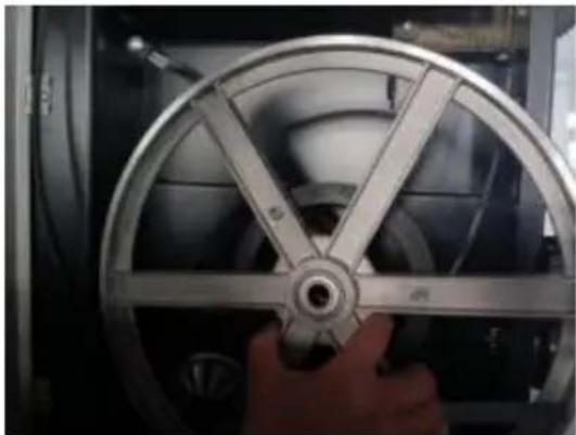
natural_image
Close-up of a hand holding a metallic wheel with visible spokes and a central hub (no text or symbols)
Gefahr!
www.vevor.com/support
VEVOR®
TOUGH TOOLS, HALF PRICE
natural_image
Technical line drawing of a mechanical device with a vertical frame and base mount (no text or symbols)NEED HELP? CONTACT US!
Have product questions? Need technical support? Please feel free contact us:
Technical Support and E-Warranty Certificate www.vevor.com/support
natural_image
Close-up of a black electronic device with attached cable and bracket (no visible text or symbols)
natural_image
Technical line drawing of a mechanical setup with a cylindrical component and base plate (no text or symbols)natural_image
Mechanical assembly diagram showing a cutting tool interacting with a base plate and mounting holes (no text or symbols present)natural_image
Simple line drawing of a cylindrical object resting on a rectangular block on a flat surface (no text or symbols)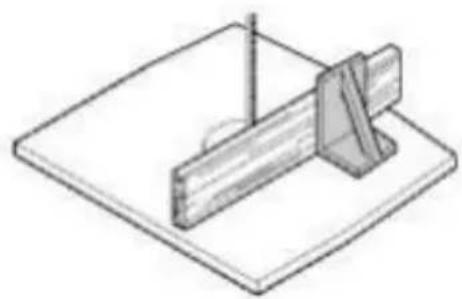
natural_image
Isometric line drawing of a mechanical setup with a rod and support bracket (no text or symbols)natural_image
Technical line drawing of a mechanical assembly with two circular components mounted on a base (no text or symbols)1. Segatura
natural_image
Interior view of a dark room with a metallic object and three small dots, no visible text or symbols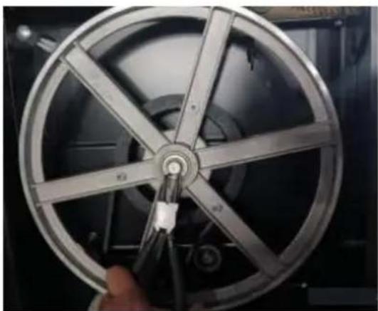
natural_image
Close-up of a metallic film reel with a hand holding a cable, showing internal components (no text or symbols visible)
natural_image
Close-up of a hand holding a metallic circular fan or wheel component (no visible text or symbols)
Pericolo!
natural_image
Technical line drawing of a mechanical device with a vertical frame and base mount (no text or symbols)NEED HELP? CONTACT US!
Have product questions? Need technical support? Please feel free contact us:
Technical Support and E-Warranty Certificate www.vevor.com/support
natural_image
Line drawing of a metal tool with a labeled dimension (24), no other text or symbols present.natural_image
Close-up of a black electronic device with visible internal components and a cable (no text or symbols)
natural_image
Technical line drawing of a mechanical setup with a cylindrical component and mounting bracket (no text or symbols)natural_image
Mechanical assembly diagram showing a cutting tool interacting with a base plate and mounting holes (no text or symbols)natural_image
Simple line drawing of a cylindrical object mounted on a square base with a pointer, no text or symbols present.
natural_image
Isometric line drawing of a mechanical setup with a rod and bracket mounted on a flat base (no text or symbols)natural_image
Technical line drawing of a mechanical assembly with two circular components mounted on a vertical frame (no text or symbols)1. Aserradura
natural_image
Close-up of a mechanical device with a light bulb mounted on a black surface, no visible text or symbols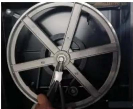
natural_image
Close-up of a metallic film reel with six spokes, held by a hand holding a cable (no visible text or symbols)
natural_image
Close-up of a hand holding a metallic wheel with visible spokes and a central hub (no text or symbols)
¡Peligro!
natural_image
Technical line drawing of a mechanical device with a vertical frame and base mount (no text or symbols)NEED HELP? CONTACT US!
Have product questions? Need technical support? Please feel free contact us:
Technical Support and E-Warranty Certificate www.vevor.com/support
natural_image
Technical line drawing of a mechanical tool or bracket with a labeled dimension (24), no other text or symbols present.natural_image
Technical line drawing of a mechanical assembly with a cylindrical component and mounting bracket (no text or symbols)natural_image
Mechanical assembly diagram showing a cutting tool interacting with a base plate and mounting holes (no text or symbols)natural_image
Simple line drawing of a cylindrical object mounted on a rectangular base, with a vertical rod inserted (no text or symbols)
natural_image
Isometric line drawing of a mechanical setup with a rod and support bracket (no text or symbols)natural_image
Technical line drawing of a mechanical assembly with two circular components mounted on a base (no text or symbols)1. Piłowanie
natural_image
Close-up of a metallic wheel with six spokes being adjusted by a tool, held by a hand (no visible text or symbols)natural_image
Close-up of a metallic wheel with five spokes, held by a hand (no visible text or symbols)
Niebezpieczeństwo!
natural_image
Line drawing of a mechanical device with a vertical frame and base platform (no text or symbols)NEED HELP? CONTACT US!
Have product questions? Need technical support? Please feel free contact us:
Technical Support and E-Warranty Certificate www.vevor.com/support

natural_image
Technical line drawing of a mechanical tool or bracket with a labeled dimension (24), no other text or symbols present.natural_image
Black and white industrial machine with a knob and handle (no visible text or symbols)
natural_image
Close-up of a black electronic device with attached cable and connector (no visible text or symbols)
natural_image
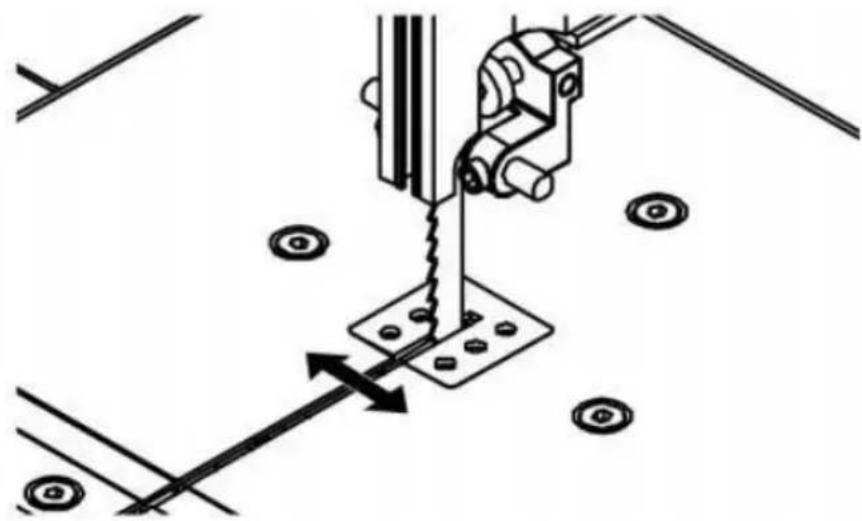
Mechanical assembly diagram showing a sewing machine needle inserted into a base plate with directional arrows indicating motion (no text or symbols)natural_image
Simple line drawing of a cylindrical object mounted on a square base with a vertical rod, no text or symbols present.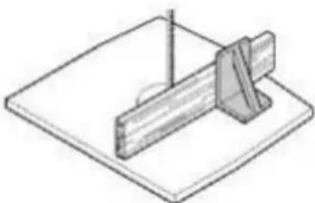
natural_image
Isometric line drawing of a mechanical setup with a wooden block and a triangular support (no text or symbols)natural_image
Technical line drawing of a mechanical assembly with two circular components mounted on a base (no text or symbols)1. Zagen
natural_image
Close-up of a hand holding a screwdriver next to a metallic film wheel (no visible text or symbols)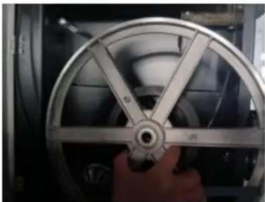
natural_image
Close-up of a hand holding a metallic wheel rim, showing the blade and central hub (no text or symbols visible)
Gevaar!
| ITEM | ONDERDEELNR. | NAAM | Hoeveelheid |
| 1 | DJ350A04100W | Onderste deur | 1 |
| 2 | GB70-85 M5×10 | Zeskantige dopsleutelset met kolomkopbout | 4 |
| 3 | DJ31505008 | Vaste blok | 2 |
| 4 | GB889-86 M6 | Borgmoer | 2 |
| 5 | BS35000000P | Lintzaagframe | 1 |
| 6 | M4×12 | Verzonken kopschroeven | 2 |
| 7 | GB70-85 M6×25 | Zeskantige dopsleutelset met kolomkopbout | 6 |
| 8 | TJ315B06012A | Duwstok | 1 |
| 9 | DJ200030904 | Haak | 1 |
| 10 | DJ350A03100 | Bovenste deur | 1 |
| 11 | GB894.1-86 15 | Borgring voor as | 2 |
| 12 | DJ350A03006 | Lagerbout Boven | 1 |
| 13 | DJ38003003 | Lagerbout Ondersteuning Boven | 1 |
| 14 | DJ250A03009 | Moer | 1 |
| 15 | GB6177-86 M8 | Zeskantige flensmoer | 4 |
| 16 | DJ350A03008 | Geleidingsplaat | 2 |
| 17 | DJ250A03007 | Schacht | 1 |
| 18 | GB896-86 6 | Gespleten ring | 2 |
| 19 | DJ315S03015 | Lente | 1 |
| 20 | DJ250A03010 | Spanbeugelframe | 1 |
| 21 | DJ350A03005 | Schuifregelaar | 1 |
| 22 | GB845-85ST4.8× 16 | Kruiskopschroef met verzonken kop | 2 |
| 23 | 31503034 | Afdekplaat | 1 |
| 24 | 31503038 | Rek | 1 |
| 25 | DJ350A03001 | Geleiderdrager Extrusie | 1 |
| 26 | DJ350A03003 | Drukplaat | 1 |
| 27 | GB70-85 M5×6 | Zeskantige dopsleutelset met kolomkopbout | 2 |
| 28 | DJ31703113 | Versnelling | 1 |
| 29 | DJ350A03007 | As voor tandwiel | 1 |
| 30 | 31503014B | Gids Draagsysteem | 1 |
| 31 | GB845-85 ST4.8×22 | Kruiskopschroef met verzonken kop | 2 |
| 32 | DJ350A03009 | Vaste staaf | 1 |
| 33 | DJ315S03012A-2 | Geleidingsas | 4 |
| 34 | GB77-85 M6×12 | Zeskantige inbusschroef | 1 |
| 35 | GB77-85 M6×8 | Zeskantige inbusschroef | 6 |
| 36 | GB/T278-89 80027 | Handelswijze | 6 |
| 37 | DJ315S03012A | Drie-rollengeleiderbehuizing | 2 |
| 38 | DJ315S03012A-3 | Schacht voor piloot | 2 |
| 39 | 31504018 | Instelknop voor vergrendeling | 2 |
| 40 | DJ350A04008 | Bovenste wiel | 1 |
| 41 | GB/T276-94 6202-2Z | Handelswijze | 4 |
| 42 | GB14-88 M8×100 | Kop vierkante nek bout | 1 |
| 43 | 31504015 | Borstelstrip | 1 |
| 44 | 31504014 | Afstandsbus | 1 |
| 45 | GB6177-86 M8 | Zeskantige flensmoer | 1 |
| 46 | GB894.1-86 12 | Borgring voor as | 1 |
| 47 | 31504012 | Spanning wiel | 1 |
| 48 | GB/T278-89 6001-2Z | Kogellager | 2 |
| 49 | 31504013 | Schuifas | 1 |
| 50 | CK-5 | Schakelaar | 1 |
| 51 | DJ31703008 | Nok | 1 |
| 52 | DJ31703009 | Afstandsbus | 1 |
| 53 | DJ350A05002 | Lamello-stekker | 1 |
| 54 | 31503006 | Instelknop | 1 |
| 55 | GB6172-86 M8 | Zeskantige dunne moer | 2 |
| 56 | DJ38003004-01 | Schroefdraadbout | 1 |
| 57 | DJ38003002 | Spanning Pan | 1 |
| 58 | GB6173-86 M20×1,5 | Zeskantige moer | 1 |
| 59 | DJ31703010 | Zitting voor snelspanas | 1 |
| 60 | DJ38003007 | Snelontgrendelingsas | 1 |
| 61 | GB6172-86 M10 | Zeskantige dunne moer | 1 |
| 62 | TJ315B03002-1 | Vergrendelingshendel | 1 |
| 63 | GB6170-86 M10 | Zeskantige moer | 1 |
| 64 | 31503008-2 | Instelknop | 1 |
| 65 | 31503008-1 | Pet | 1 |
| 66 | GB5783-86 M8x45 | Zeskantbout | 1 |
| 67 | GB5783-86 M8x16 | Zeskantbout | 8 |
| 68 | GB97.1-85 8 | Wasmachine | 16 |
| 69 | 31503007 | Vleugelmoer | 5 |
| 70 | GB5783-86 M6X10 | Zeskantbout | 4 |
| 71 | GB97.1-85 6 | Wasmachine | 38 |
| 72 | RWL1000F0217 | Katrolmotor (rechts) | 1 |
| 73 | DT/SB030 | Vergrendelingsknop | 1 |
| 74 | DJ200030407A | Lente | 1 |
| 75 | DJ250A03016B-2 | Basis van de afstelknop | 1 |
| 76 | GB5783-86 M8×55 | Zeskantbout | 1 |
| 77 | DJ350A04003 | Lagerbout Onder | 1 |
| 78 | 31604006 | Zuigconnector | 1 |
| 79 | DJ350A04009 | Zitting onderste geleider | 1 |
| 80 | DJ315B03024 | Vergrendelingspen | 1 |
| 81 | RWL1000F0216 | Katrolmotor (links) | 1 |
| 82 | YYL8024EV-T | Motor | 1 |
| 83 | DJ315D03001 | Moer | 1 |
| 84 | TJ31502012 | Handwiel | 1 |
| 85 | DJ350A02003 | As voor tandwiel | 1 |
| 86 | TJ31503014 | Versnelling | 2 |
| 87 | DJ315B02008 | Vergrendelingshendel | 1 |
| 88 | DJ31505007 | Vaste plaat | 2 |
| 89 | DJ350A02002 | Tafeldraaipunt | 2 |
| 90 | DJ350A02100 | Tafeldraaipunt lager | 1 |
| 91 | DJ350A02006 | Wijzer | 1 |
| 92 | GB818-85 M4×6 | Kruiskopschroef met verzonken kop | 1 |
| 93 | GB5783-86 M6X10 | Zeskantbout | 4 |
| 94 | GB/T801-98 M8×90 | Kop vierkante nek bout | 2 |
| 95 | DJ350A02001F | Tafel | 1 |
| 96 | 31502009 | Tabel invoegen | 1 |
| 97 | DJ315S02001-16 | Vleugelmoer | 2 |
| 98 | DJ315S02001-18 | Pet | 2 |
| 99 | DJ315S02001-09 | Hekbeugel | 1 |
| 100 | GB/T801-98 M6×50 | Kop vierkante nek bout | 2 |
| 101 | TJ250C04003A | Schutting | 1 |
| 102 | DJ315S02001-05 | Drukplaat | 1 |
| 103 | TJ315FA04002C | Hek drager | 1 |
| 104 | RTS250G04012 | Kunststof drukplaat | 1 |
| 105 | GB845-85 ST3.5×9.5 | Kruiskopschroef met verzonken kop | 2 |
| 106 | RTS250G04011 | Nok | 1 |
| 107 | RTS250G06011-1 | Hendel | 1 |
| 108 | DJ315S02001-20 | Bevestigingsplaat | 1 |
| 109 | DJ315S02001-08 | Schacht | 1 |
| 110 | RTS250G06010 | Wijzer | 1 |
| 111 | GB70-85 M5X12 | Zeskantige dopsleutelset met kolomkopbout | 2 |
| 112 | RTS250G04002-2 | Afdekplaat Rechts | 1 |
| 113 | DJ350A04010A | Hekdrager extrusie | 1 |
| 114 | 31502015 | Vleugelbout | 4 |
| 115 | RTS250G04002-1 | Afdekplaat links | 1 |
| 116 | TJ25003004A-2 | Hendel | 2 |
| 117 | TJ25003004A-1 | Handwiel | 2 |
| 118 | 31504019 | Instellen kraag | 1 |
| 119 | DJ350A04006A | As voor riemspanning | 1 |
| 120 | GB818-85 M4×35 | Kruiskopschroef met verzonken kop | 4 |
| 121 | DJ31705002 | Microschakelaar afdekking | 2 |
| 122 | HY50 | Microschakelaar | 2 |
| 123 | RWLD0120 | Microschakelaar doos | 2 |
| 124 | GB6170-86 M4 | Zeskantige moer | 8 |
| 125 | GB862.1-87 3 | Borgring | 4 |
| 126 | GB845-85 ST3.5×9.5 | Kruiskopschroef met verzonken kop | 2 |
| 127 | DJ350A04002 | Mesbescherming | 1 |
| 128 | DJ35003003 | Rubberen band | 2 |
| 129 | Z/813 | Driehoeksriem | 1 |
| 130 | DJ350A05001GA/2780×12,5×0,5 4T.PI | Blad | 1 |
| 131 | GB818-85 M5×12 | Kruiskopschroef met verzonken kop | 2 |
| 132 | DJ350A04008 | Onderste wiel | 1 |
| 133 | DJ315S03014 | Afstandsbus | 2 |
| 134 | 31504020W | Katrol | 1 |
| 135 | GB93-87 6 | Veerring | 3 |
| 136 | GB6173-86 M20×1,5 | Zeskantige moer | 1 |
| 137 | GB93-87 20 | Veerring | 1 |
| 138 | GB889-86 M5 | Borgmoer | 2 |
| 139 | TYA010010 | Knop | 2 |
| 140 | DJ31703026 | Plak invoegen | 2 |
| 141 | GB818-85 M4×12 | Kruiskopschroef met verzonken kop | 4 |
| 142 | GB6170-86 M5 | Zeskantige moer | 4 |
| 143 | DJ315B02006-4 | Scharnierende bouten | 1 |
| 144 | DJ315B03015 | Vergrendel de knop | 1 |
| 145 | GB5783-86 M6X16 | Zeskantbout | 1 |
| 146 | GB/T1792 A16 | vlinderring | 1 |
| 147 | GB/T96.2 6 | Wasmachine | 1 |
| 148 | DJ315B02006-1 | Hoekmeter | 1 |
| 149 | DJ315B02006-3A | Geleidestang | 1 |
| 150 | GB894.1-86 16 | Borgring voor as | 1 |
| 151 | RWL1000F0212 | Mouw | 1 |
| 152 | RWL1000F0213A | Lente | 1 |
| 153 | GB77-85 M6×10 | Zeskantige inbusschroef | 2 |
| 154 | GB/T1096/4×80 | Sleutel | 1 |
VEVOR®
TOUGH TOOLS, HALF PRICE
Technisch Ondersteuning en E-garantiecertificaat www.vevor.com/support
VEVOR®
TOUGH TOOLS, HALF PRICE
natural_image
Line drawing of a mechanical device with a vertical frame and base mount (no text or symbols)NEED HELP? CONTACT US!
Have product questions? Need technical support? Please feel free contact us:
Technical Support and E-Warranty Certificate www.vevor.com/support

natural_image
Technical line drawing of a mechanical tool or bracket with a labeled dimension (24), no other text or symbols present.| DELNR. | BESKRIVNING | ANTAL |
| 1 | Ben | 4 |
| 2 | Lång anslutningsplatta | 2 |
| 3 | Kort anslutningsplatta | 2 |
| 4 | Tumskruv | 4 |
| 5 | Skruv M8×55 | 1 |
| 6 | vagnbult M8×16 | 16 |
| 7 | Sexkantsmutter M8 | 17 |
| 8 | Platt bricka 8 | 24 |
| 9 | "L" skruv | 1 |
| 10 | Sexkantsmutter M6 | 1 |
| 11 | Rycka | 1 |
| 12 | Insexnyckel SW 3 | 1 |
| 13 | Skruv M8×16 | 4 |
Montering
natural_image
Close-up of a black electronic device with visible internal components and a cable (no text or symbols)
natural_image
Technical line drawing of a mechanical setup with a cylindrical component and base plate (no text or symbols)natural_image
Mechanical assembly diagram showing a cutting tool interacting with a base plate and circular components (no text or symbols)natural_image
Simple line drawing of a cylindrical object mounted on a square base with a vertical rod above (no text or symbols)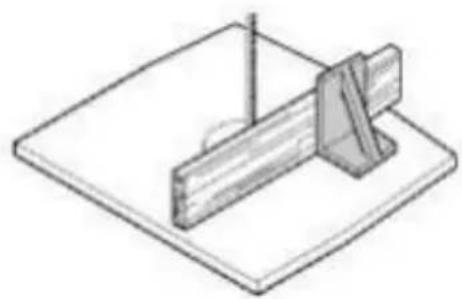
natural_image
Isometric line drawing of a mechanical setup with a wooden block and a triangular support (no text or symbols)natural_image
Technical line drawing of a mechanical assembly with two circular components mounted on a base (no text or symbols)1. Sågning
natural_image
Close-up of a hand holding a metallic wheel with a circular head, no visible text or symbols
Fara!
| PUNKT | DELNR. | NAMN | Antal |
| 2 | DJ350A01202 | Ben | 4 |
| 3 | DJ350A01204 | Kort anslutningsplatta | 2 |
| 4 | DJ350A01203 | Lång anslutningsplatta | 2 |
| 5 | GB/T801 M8 × 16 | vagnsbult | 16 |
| 6 | GB/T97.1 8 | Platt bricka | 16 |
| 7 | GB/T6170/1 M8 | Sexkantmutter | 16 |