WCP4800 - Mechanical chipper SCHEPPACH - Free user manual and instructions
Find the device manual for free WCP4800 SCHEPPACH in PDF.

| Product type | Shredder (mechanical chipper) |
| Brand | Scheppach |
| Model | WCP4800 |
| Engine | Single-cylinder 4-stroke, air-cooled |
| Engine power | 4.1 kW / 5.58 HP |
| Displacement | 196 cm³ |
| Rated speed | 3600 min⁻¹ |
| Dimensions (L × W × H) | 670 × 1180 × 1470 mm |
| Weight | 97 kg |
| Wheel diameter | 295 mm |
| Max. loading opening | 560 × 370 mm |
| Max. ejection opening | 120 × 85 mm |
| Max. branch diameter | 70 mm |
| Blade disc | Diameter 400 × 10 mm |
| Knife | 110 × 42 mm, 2 knives |
| Fuel | Unleaded Super E5 gasoline (max 5% bioethanol) |
| Fuel tank capacity | 3.6 L |
| Engine oil | SAE 10W-30, capacity 0.6 L |
| Spark plug | F6RTC |
| Guaranteed sound power level | 109 dB |
| Sound pressure level | 86 dB |
| CO₂ emission | 925.8 g/kWh |
| Main functions | Shredding branches, hedge trimmings, garden waste |
| Maintenance and cleaning | Regular cleaning, oil change, check air filter and spark plug |
| Safety | Hearing and eye protection, circuit breaker, automatic low oil level shutdown |
| Spare parts available | Knife (ref. 7904401701), counter blade (ref. 5904411026) |
| General information | Private garden use, max 50 h/year, do not use indoors |
Frequently Asked Questions - WCP4800 SCHEPPACH
User questions about WCP4800 SCHEPPACH
0 question about this device. Answer the ones you know or ask your own.
Ask a new question about this device
Download the instructions for your Mechanical chipper in PDF format for free! Find your manual WCP4800 - SCHEPPACH and take your electronic device back in hand. On this page are published all the documents necessary for the use of your device. WCP4800 by SCHEPPACH.
USER MANUAL WCP4800 SCHEPPACH
natural_image
Technical line drawing of a mechanical pump or milling machine with a wheel and side-mounted blade (no text or symbols)
WCP4800
| DE | Benzin-MesserhäckslerOriginalbetriebsanleitung | 6 |
| GB | Petrol garden shreddeTranslation of original instruction manual | 25 |
| FR | Broyeur à végétaux thermiqueTraduction des instructions d'origine | 41 |
| SE | Bensindriven kompostkvarnÖversättning av original-bruksanvisning | 58 |
1


natural_image
Technical line drawing of a mechanical assembly with labeled components (no readable text or symbols)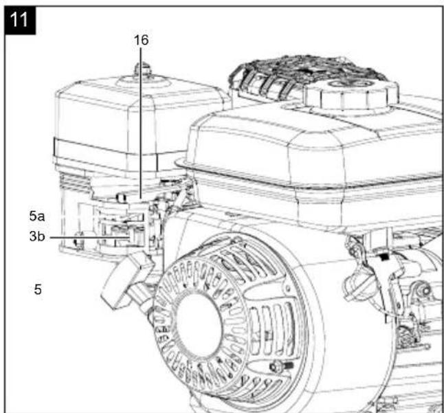
natural_image
Technical line drawing of a mechanical assembly with labeled parts (no readable text or symbols)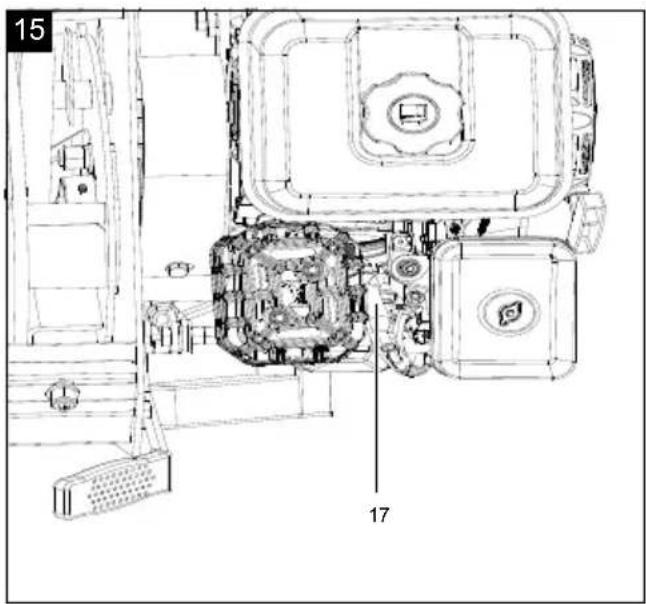
Günzburger Straße 69
D-89335 Ichenhausen
Verehrter Kunde,
Homepage: https://www.scheppach.com/de/service
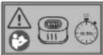
Explanation of the symbols on the product
Symbols are used in this manual to draw your attention to potential hazards. The safety symbols and the accompanying explanations must be fully understood. The warnings themselves will not rectify a hazard and cannot replace proper accident prevention measures.
 | Warning - Read the operating manual to reduce the risk of injury. |
 | Wear hearing protection. Wear safety goggles. |
 | Wear a dust protection mask. When machining wood and other materials, harmful dust may be generated. Do not machine material containing asbestos! |
 | Wear sturdy footwear. |
 | Wear protective gloves. |
 | Attention: Risk of injury! Do not reach or climb into the feed hopper or ejection shaft during operation. |
 | Removing or modifying protective or safety equipment is prohibited. |
 | Hot surface! Touching can cause burns.Only carry out servicing, maintenance and cleaning work when the engine has cooled down. |
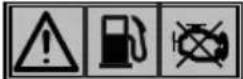
 | Naked flames or smoking near the product is strictly prohibited! |
 | Guaranteed sound power level of the product |
 | Do not refuel while the engine is hot or running. |
 | The exhaust gases are toxic. Do not operate the engine in areas that are not ventilated. |
 | Make sure that other persons maintain a sufficient safety distance. |
 | The exhaust gases are toxic. Do not operate the engine in areas that are not ventilated. |
 | Hurled objects and rotating parts can cause severe injuries. |
 | Danger! Rotating blades. Keep hands and feet outside of the openings when the product is running. |
 | Danger! Rotating blades. Keep hands and feet outside of the openings when the product is running. |
 | Remove the spark plug connector prior to all maintenance work. |
 | Hot surface! Touching can cause burns. |
 | Clean the air filter at regular intervals. |
 | Attention! Failure to observe the safety signs and warning information affixed to the product and failure to observe the safety and operating information can result in serious injury or even death. |
 | Danger of poisoning! Only use the device outdoors and never in closed or poorly ventilated rooms. |
 | Operating materials are flammable and explosive - danger of burning. Do not refuel while the engine is hot or running. |
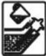 | Check the oil level regularly. |
 | Choke closed, fuel valve open. |
 | Speed adjustmentHare = fastTortoise = slow |
 | The product complies with the applicable European directives. |
Table of contents: Page:
- Introduction....28
- Product description (Fig. 1 - 15)....28
- Scope of delivery (Fig. 2)....28
- Proper use 29
- General safety instructions.... 29
- Residual risks 31
- Technical data.... 31
- Unpacking 31
- Assembly 32
- Before commissioning 32
- Starting operation (Fig. 1, 10, 11)....33
- Working instructions 34
- Cleaning & maintenance 35
- Transport....38
- Storage 38
- Repair & ordering spare parts 39
- Disposal and recycling....39
- Troubleshooting 40
- Declaration of conformity 75
1. Introduction
Manufacturer:
Scheppach GmbH
Günzburger Straße 69
D-89335 Ichenhausen
Dear Customer,
We hope your new product brings you much enjoyment and success.
Note:
In accordance with the applicable product liability laws, the manufacturer of this product assumes no liability for damage to the product or caused by the product arising from:
- Improper handling
- Failure to comply with the operating manual
• Repairs carried out by third parties, unauthorised specialists
• Installing and replacing non-original spare parts - Improper use
Note:
The operating manual is part of this product. It includes important instructions for the safe, proper and economic operation of the product, for avoiding danger, for minimising repair costs and downtimes and for increasing the reliability and extending the service life of the product. In addition to the safety instructions in this operating manual, you must also observe the regulations applicable to the operation of the product in your country.
Familiarise yourself with all operating and safety instructions before using the product. Only operate the product as described and for the specified areas of application. Keep the operating manual in a good place and hand over all documents when passing the product on to third parties.
2. Product description (Fig. 1 - 15)
- Clutch lever
- Lever (guide plate)
- Fuel tank
3a. Fuel filler cap
3b. Fuel valve -
Air filter cover
4a. Wing nut (outer)
4b. Wing nut (inner)
4c. Air filter -
Pull starter
5a. Choke - On/off switch
- Engine unit
7a. Screw (M8) (pre-mounted)
7b. Nut (M8) (pre-mounted) - Transport handle
- Feed hopper
9a. Feed hopper (top)
9b. Feed hopper (bottom)
9c. Carriage bolt (M6) (pre-mounted)
9d. Washer (M6) (pre-mounted)
9e. Nut (M6) (pre-mounted) - Ejection shaft
10a. Guide plate
10b. Screw (M8) (pre-mounted)
10c. Nut (M8) (pre-mounted)
10d. Retaining plate (pre-mounted)
10e. Nut (pre-mounted) - Transport wheel
- Grease nipple
- Cutting blade
13a. Screw
13b. Counter-blade - Oil dipstick
- Oil drain screw
- Throttle
- Spark plug
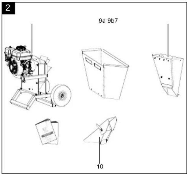
3. Scope of delivery (Fig. 2)
| Item | Quantity | Designation |
| 7 | 1x | Engine unit |
| 9 a | 1x | Feed hopper (top) |
| 9b | 1x | Feed hopper (bottom) |
| 10 | 1x | Ejection shaft |
| 1x | Spark plug wrench | |
| 1x | Petrol-powered chopper operating manual | |
| 1x | Engine operating manual (English) |
4. Proper use
The product is suitable for private use in private gardens and allotments. A product for private gardens and allotments refers to a device with an annual operating time generally not exceeding 50 hours, during which time the device is primarily used to shred organic household and garden waste. Public facilities, sporting halls, and agricultural/forestry applications are excluded.
Proper use includes shredding
- All types of branches up to a maximum diameter of 70 mm (depending on the type of wood and freshness),
• Hedges and tree cuttings, - Shrubs and bushes,
- Wilting, moist, garden waste that has already been stored for several days, alternating with branches.
The product may only be used in the intended manner. Any use beyond this is improper. The user/operator, not the manufacturer, is responsible for damages or injuries of any type resulting from this.
An element of the intended use is also the observance of the safety instructions, as well as the assembly instructions and operating information in the operating manual.
Persons who operate and maintain the product must be familiar with the manual and must be informed about potential dangers.
The liability of the manufacturer and resulting damages are excluded in the event of modifications of the product.
The product may only be operated with original parts and original accessories from the manufacturer.
The safety, operating and maintenance specifications of the manufacturer, as well as the dimensions specified in the technical data, must be observed.
Please note that our products were not designed with the intention of use for commercial or industrial purposes. We assume no guarantee if the product is used in commercial or industrial applications, or for equivalent work.
The manufacturer is not liable for damage caused by improper use or incorrect operation.
Explanation of the signal words in the operating manual
DANGER
Signal word to indicate an imminently hazardous situation which, if not avoided, will result in death or serious injury.
⚠ WARNING
Signal word to indicate a potentially hazardous situation which, if not avoided, could result in death or serious injury.
CAUTION
Signal word to indicate a potentially hazardous situation which, if not avoided, could result in minor or moderate injury.
ATTENTION
Signal word to indicate a potentially hazardous situation which, if not avoided, could result in product or property damage.
5. General safety instructions
⚠ WARNING - Read all safety information, instructions, illustrations and technical data for this product.
Save all warnings and instructions for future reference.
- Do not use the product on a surface paved with gravel where ejected material could cause injuries.
- Only use the product outdoors (i.e. not close to a wall or another rigid object) and on a solid, level surface.
- ATTENTION Always check whether the feed funnel is empty and that the blades are not blocked prior to starting the engine!
-
ATTENTION Remaining in the petrol impact garden shredder's danger area when starting and operating is prohibited.
-
Never shred while people, especially children or animals are nearby.
• Who is not permitted to use the product: - Persons who are unfamiliar with handling it.
- Children may not work with this product.
- People under the influence of alcohol, drugs and medication, as well as those who are tired or ill.
- Do not run the combustion engine in closed rooms in which hazardous carbon monoxide can collect.
- Wear hearing protection and safety goggles during the entire operating period.
- Do not wear loose-fitting clothing or clothing with hanging belts or cords.
- Ensure that all nuts, pins and screws are securely tightened so that the product is in a safe working condition.
- Prior to commissioning, all covers and safety devices must be mounted correctly. Damaged or illegible stickers must be replaced.
5.1 Handling
- Before starting the product, make sure that the feed hopper is empty.
- Keep your head and body a safe distance from the loading slot.
- Do not place hands, other parts of the body and clothing in the feed hopper, the ejection shaft or in the vicinity of other moving parts.
• Always pay attention to your balance and firm footing. Do not bend over or stand higher than the product when throwing material in.
• Always stay outside of the ejection zone when commissioning the product. - Ensure that hard objects such as metal, stones, glass or other foreign objects are not contained in the material being thrown in.
-
If foreign objects get into the cutting tool or the product makes unusual noises or vibrates abnormally, switch the engine off immediately and allow the product to run down. Remove the spark plug connector and perform the following steps:
-
Check the product for damage.
- Check all parts for firm seating, retighten them if necessary.
- Repair or replace any damaged parts with parts that are of equivalent quality.
- Do not let processed material pile up within the ejection area; this could prevent proper ejection and cause a kick-back of the material through the feed hopper.
- In the event of blockages in the loading or discharge area of the product, switch off the engine and pull the spark plug connector before removing material remaining in the infeed opening or ejection shaft.
• Make sure that the engine is free of waste and other accumulations to safeguard the engine from damage or possible fire. - Remember that when the starter mechanism with motorised products is commissioned, the cutting tool also starts operating.
• Make sure all covers and deflectors are in their place and in good working condition. - Do not change the speed governor setting of the engine or over-rev it. The safe maximum working speed regulates the speed and protects the engine and all rotating parts from damage due to excess speed. Contact customer service if you have any problems.
- Do not transport or tilt the product with the engine running.
- Switch the engine. off and pull out the spark plug connector as soon as you leave your workstation.
5.2 Handling fuel
ATTENTION
Use only E5 unleaded petrol as fuel.
DANGER
Risk of fire and explosion!
When filling, fuel may ignite and even explode. This can lead to severe burns or death.
- Only store fuel in containers (canisters) designed for this purpose.
- The tank caps must always be properly screwed on and tightened.
- Fuel must be filled before starting the engine. While the engine is running or immediately after switching off the product, do not open the fuel filler cap or add fuel.
- Before refuelling, switch off the combustion engine and let it cool down.
- Refuel outdoors only and do not smoke while refuelling.
- Never store the product with fuel in the tank inside a building. Any fuel vapours produced can come into contact with naked flames or sparks and ignite.
- Do not place the product and fuel tank near heaters, radiant heaters, welding machines or other sources of heat.
- If fuel has overflowed, do not start the combustion engine until the area contaminated with fuel has been cleaned.
Avoid starting the engine until the fuel vapours have evaporated (wipe dry).
- For safety reasons, check fuel line, fuel tank, fuel cap and connections regularly for damage, ageing (brittleness), tight fit and leaks and replace if necessary.
6. Residual risks
The product has been built according to state-of-the-art and the recognised technical safety rules. However, individual residual risks can arise during operation.
- Residual risks can be minimised if the "Safety Instructions" and the "Intended Use" together with the operating manual as a whole are observed.
- Use the product in the way that is recommended in this operating manual. This is how to ensure that your product provides optimum performance.
- Prevent the product being unintentionally started up.
- Keep your hands away from the working area when the product is in operation.
- Comply with the stipulated maintenance and safety instructions in the operating instructions.
• Furthermore, despite all precautions having been met, some non-obvious residual risks may still remain.
7. Technical data
| Engine / drive | 1-cylinder 4-stroke engine / air-cooled |
| Engine output | 4.1 kW / 5.58 PS |
| Displacement | 196 cm^3 |
| Rotation speed | 3600 rpm |
| Dimensions L x W x H | 670x1180x1470 mm |
| Wheel ø | 295 mm |
| Infeed height | 1300 mm |
| Ejection height | 800 mm |
| Infeed opening max. | 560 x 370 mm |
| Ejection opening max. | 120 x 85 mm |
| Branch thickness max ø | 70 mm |
| Cutter disc ø | 400 x 10 mm |
| Cutting blade | 110 x 42 mm |
| Number of cutting blades | 2 |
| Fuel | Normal petrolUnleaded max. 5%Bioethanol |
| Tank capacity / fuel 3.6 l |
| Engine oil SAE 10W-30 |
| Tank capacity / oil 0.6 l |
| Spark plug F6RTC |
| CO2 output 925.8 g/kWh |
| Weight 97 kg |
Subject to technical changes!
Noise and vibration
⚠ Warning: Noise can have serious effects on your health. If the machine noise exceeds 85 dB, please wear suitable hearing protection.
Information about the noise level measured in accordance with applicable standards (EN ISO 3744:1995, ISO 11094:1991):
Noise data
| Sound power level L_WA | 109 dB |
| Sound pressure level L_pA | 86 dB |
| Uncertainty K_wa/pA | 3 dB |
8. Unpacking
- Open the packaging and carefully remove the product.
- Remove the packaging material, as well as the packaging and transport safety devices (if present).
- Check whether the scope of delivery is complete.
- Check the product and accessory parts for transport damage. In the event of complaints the carrier must be informed immediately. Later claims will not be recognised.
- If possible, keep the packaging until the expiry of the warranty period.
- Familiarise yourself with the product by means of the operating instructions before using for the first time.
- With accessories as well as wearing parts and replacement parts use only original parts. Spare parts can be obtained from your specialist dealer.
- When ordering please provide our article number as well as type and year of manufacture for the product.
⚠ WARNING!
The product and the packaging material are not children's toys! Do not let children play with plastic bags, films or small parts! There is a danger of choking or suffocating!
9. Assembly
Attention!
Always make sure the product is fully assembled before commissioning!
Tool required:
* = not included in the scope of delivery
- Open-ended spanner size 10*
- 2x open-ended spanner, size 13*
- Open-ended spanner, size 18
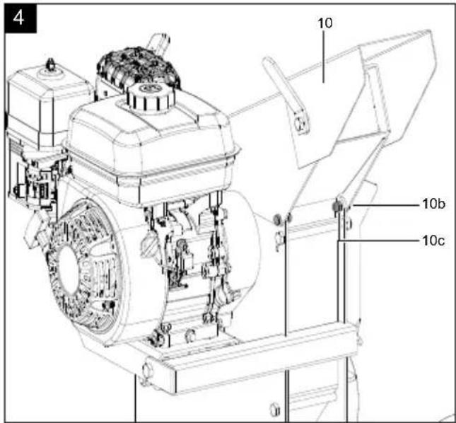
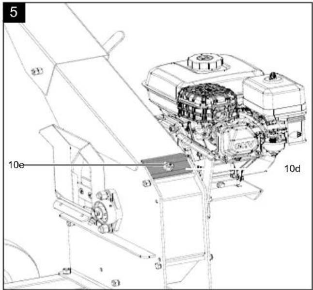
9.1 Fitting the ejection shaft (10) (Fig. 3, 4, 5)
-
Remove the pre-assembled screws (10b) and nuts (10c). Use two open-ended spanners, size 13.
-
Position the ejection shaft (10) on the surface intended for the engine unit (7).
-
Ensure that the retaining plate (10d) sits correctly on the ejection shaft (10). Fix the retaining plate (10d) in place with the nut (10e). Use an open-ended spanner, size 18.
-
Fasten the ejection shaft (10) with the previously removed screws (10b) and nuts (10c). Tighten up the screws evenly. Use two open-ended spanners, size 13.
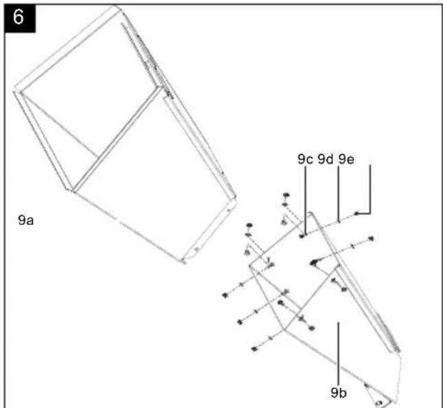
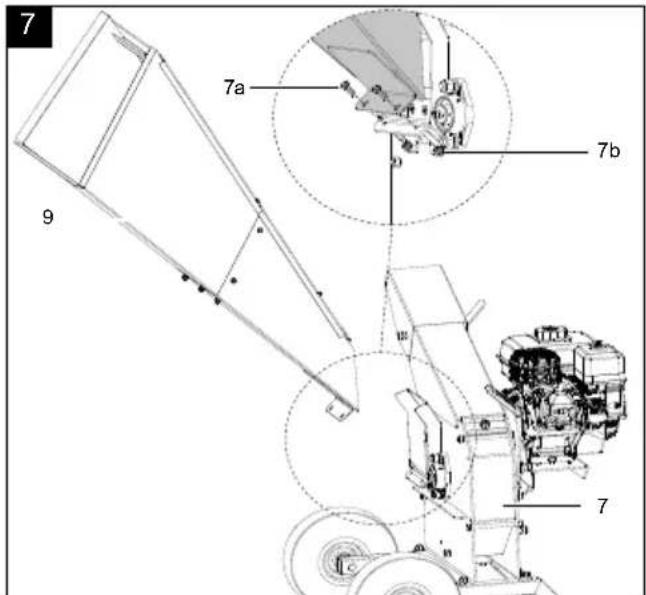
9.2 Fitting the feed hopper (9) (Fig. 6, 7)
-
Remove the pre-assembled carriage bolts (9c), washers (9d) and nuts (9e). Use an open-ended spanner, size 10.
-
Guide the top feed hopper (9a) into the bottom feed hopper (9b).
-
Align both hopper parts precisely.
-
Attach both hopper parts using the nine carriage bolts (9c), washers (9d) and nuts (9e). Use an open-ended spanner, size 10.
Note: Fit the carriage screws (9c) from the inside out.
-
Remove the two pre-mounted screws (7a) and nuts (7b) on the engine unit. Use two open-ended spanners, size 13.
-
Hang the feed hopper (9) in the mounting intended on the engine unit (7).
-
Fasten the feed hopper (9) to the engine unit (7) with the previously removed screws (7a) and nuts (7b). Tighten the screws (7a). Use two open-ended spanners, size 13.
9.3 Check the tyre pressure
The transport wheels (11) are already filled when delivered. Check the tyre pressure. The recommended tyre pressure is 1.6 to 1.8 bar.
Check the tyre pressure at regular intervals with a commercially available air pump.
Note: If you notice that the wheels are damaged, contact the customer service or a specialist workshop.
10. Before commissioning
⚠ WARNING
For your own safety, please thoroughly read this manual and the general safety instructions before turning the product on. If you give the product to third parties, always include these operating instructions.
ATTENTION
Always make sure the product is fully assembled before commissioning!
ATTENTION
At initial start-up, engine oil and fuel must be filled.
ATTENTION
Product damage!
If the product is operated without oil or with too little oil or with used oil, this can lead to product damage.
- Fill with oil before start-up. The product is delivered without oil.
- Do not use used oil!
- Check the oil level before each start-up.
ATTENTION
Environmental damage!
Spilled oil can pollute the environment permanently. The liquid is highly toxic and can quickly lead to water pollution.
- Fill/empty oil only on level, paved surfaces.
- Use a filling nozzle or funnel.
- Collect drained oil in a suitable container.
- Wipe up spilled oil carefully immediately and dispose of the cloth according to local regulations.
- Dispose of oil as per local regulations.
⚠️ DANGER
Danger to life!
Fuel is toxic and highly flammable.
⚠️ DANGER
Risk of fire and explosion!
Only fill the fuel when the engine is switched off and has cooled down. Do not smoke when refuelling the product.
⚠️ DANGER
Risk of fire and explosion!
When filling, fuel may ignite and even explode. This can lead to severe burns or death.
WARNING
Health hazard!
Inhalation of fuel / lubricating oil vapours and exhaust gases can cause serious damage to health, unconsciousness and in extreme cases death.
- Do not breathe fuel / lubricating oil vapours and exhaust gases.
- Empty out fuel only outdoors.
ATTENTION
The product is delivered without engine oil. Therefore, ensure that you add oil before starting it up. Use SAE10W-30 oil for this.
The engine oil affects the performance and service life of the product.
ATTENTION
The product is delivered without fuel. It is therefore essential to fill with fuel before commissioning. Use Super E5 petrol for this.
Tool required:
Funnel*
Rag/cloth*
* = may not be included in the scope of delivery!
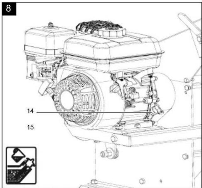
10.1 Filling up with engine oil (Fig. 8)
- Place the product on a level, even surface.
- Unscrew the oil dipstick (14).
- Fill the engine oil tank using a funnel.
- Do not exceed the maximum filling level (see Technical Data).
-
Carefully fill the engine oil to the lower edge of the filling nozzle.
-
Wipe the oil dipstick (14) with a clean, lint-free cloth.
- Reinsert the oil dipstick (14) without screwing the oil dipstick (14) back on.
- Pull the oil dipstick (14) out and read the oil level in the horizontal position. The oil level must be between L (low) and H (high) on the oil dipstick (14).
- If the oil level is too low, add the recommended amount of engine oil (see Technical Data).
- Then screw the oil dipstick (14) in again.
10.2 Filling in fuel (Fig. 9)
- Switch off the engine and let it cool down.
- Keep heat, flames and sparks away.
- Only fill up with fuel outdoors.
- Wear protective gloves.
- Avoid contact with skin and eyes.
- Avoid using old or contaminated fuel and do not use fuel-oil mixtures.
• Make sure that no dirt or water gets into the fuel tank.
- Only use Super E5 petrol for this. The engine is optimised for operation with unleaded fuel.
- Start the product at a distance of at least 3 m from the fuel filling point.
- Check the fuel level every time before commissioning.
- Clean the tank cover (3a) and the area around the filling nozzle to prevent dirt or foreign objects from entering the fuel tank (3).
- Carefully open the tank cover (3a) so that any possible overpressure can be relieved.
- Check the fuel level by visual inspection.
- Fill the fuel tank (3) with petrol using a funnel.
- Do not exceed the maximum filling level (see Technical Data).
- Carefully fill the fuel up to the lower edge of the filling port.
- Seal the tank cover (3a) again by placing it straight on and turning it clockwise. Make sure that the tank cover (3a) is completely sealed to prevent leaks and evaporation.
- Clean the tank cover (3a) and the surroundings.
- Check the fuel tank (3) and fuel lines for leaks.
11. Starting operation (Fig. 1, 10, 11)
⚠ Attention!
Always make sure the product is fully assembled before commissioning!
Notes:
• Good work results require well sharpened blades.
- Blunt blades reduce the cutting performance and impair the work process! Sure signs of blunt blades are leaving an indentation, reduced performance and a poor cutting pattern.
• Always stand to the side of the filling funnel when filling the feed hopper.
- If the engine is cold, set both the choke lever and the fuel valve to the "ON" position. If the engine is warm, the choke is not required.
- Remaining in the chopper's danger area when starting and during operation is prohibited.
• Always check whether the feed funnel is empty and that the blades are not blocked prior to starting the engine!
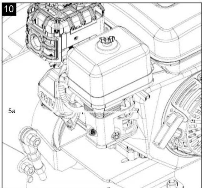
11.1 Starting the engine
WARNING
This must be disengaged before starting the engine!
- Press the clutch lever (1) down all the way to disengage the engine.
-
The engine only needs to be disengaged for the start process!
-
Slide the choke lever (5a) to the left and open the fuel valve (3b) on the engine to the right.
- Position the throttle (16) in the middle.
- Turn the on/off switch (6) to "ON".
- Now pull the pull starter (5) slowly several times so that fuel can flow from the fuel tank (3) to the engine.
- Start the engine by pulling the pull starter (5) quickly. If the engine does not start, repeat the process.
- Let the engine warm up for several seconds.
- Use the throttle (16) to set the speed to full throttle.
- Slide the choke lever (5a) to the right to the "OFF" position slowly.
- Position the clutch lever (1) upwards slowly to engage the engine and drive the cutter disc. Engaging too quickly can stall the engine.
- If the engine does not start even after several attempts, read the Troubleshooting chapter.
11.2 Shutting the engine off
Allow the product to run for a short time (approx. 30 seconds) switching it off so that the engine can cool down.
- Turn the on/off switch (6) to "OFF".
- Set the fuel valve (3b) to the "OFF" position.
ATTENTION
Cutter disc continues to run for a few seconds!
11.3 Automatic oil cut-off
The automatic oil cut-off system responds when there is too little engine oil.
- If the oil level is too low, top up the oil as described in 10.1.
- Start the engine as described in 11.1.
11.4 Adjusting the guide plate (10a)
The ejection height can be adjusted with the guide plate (10a).
- Loosen the lever (2) on the guide plate (10a).
- Set the guide plate (10a) to the desired angle.
- Fix the guide plate (10a) by tightening the lever (2) again.
12. Working instructions
ATTENTION
Keep a sufficient distance from the product when shredding, as long branches can kick out when being pulled in. There is a danger of injury.
- Hold branches when feeding them into the product until they are automatically drawn in.
• Alternate the chopping of wilting garden waste and branches that have been stored for several days with branches in order to prevent clogging. - Before shredding, remove roots from attached soil debris and stones.
- Do not shred soft, moist material such as kitchen waste, but compost it directly.
- Allow the roller shredder to fully shred the chopped material introduced before you introduce any new materials.
- Do not use your hands to push down the chopped material, only use a specialist plug for this or other chopped material.
- Switch off the product after the work is completed and disconnect the spark plug cable to prevent an unintentional start-up.
- Save a few dry branches until the end to use them to help clean.
- If material becomes jammed, first press the off switch to stop the product. Then pull out the spark plug cable to prevent an unintentional start-up. Do not use your hands to loosen and remove stuck material or blockages, only use suitable tools (e.g. wooden stick).
13. Cleaning & maintenance
WARNING
Have maintenance and repair tasks that are not described in this operating manual, carried out by a specialist workshop. Use only original spare parts.
WARNING
Improper maintenance or cleaning work can cause injuries!
WARNING
The product may start unexpectedly and cause injuries and burns during cleaning, repair and maintenance work.
- Switch the product off.
- Remove the spark plug connector from the spark plug.
- Please note that the cutter disc keeps turning for a few seconds.
- Allow the product to cool down.
WARNING
Carry out a visual and functional check/maintenance regularly/daily and before commissioning to ensure that the product is in good operating condition.
- Incorrect maintenance, use of non-conforming replacement parts, or removal or modification of safety equipment may lead to severe property or personal damages.
- If this work cannot be carried out by the user themselves, see a specialist dealer.
13.1 Cleaning
- Keep protective devices, air vents and the engine housing as free of dust and dirt as possible. Rub the product clean with a clean cloth or blow it off with compressed air at low pressure.
• We recommend that you clean the product directly after every use. - Clean the product at regular intervals using a damp cloth and a little soft soap. Do not use any cleaning products or solvents; they could attack the plastic parts of the product. Make sure that no water can penetrate the interior of the product. Water penetration increases the risk of an electric shock.
13.2 Maintenance
Tool required:
* = not included in the scope of delivery
- Installation spanner
- Rag/cloth*
- Collection tray*
- Grease gun*
- Open-ended spanner AF10*
- Open-ended spanner size 13*
- Open-ended spanner size 16*
- Allen screw size 5*
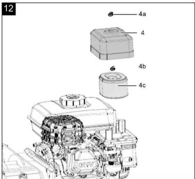
13.2.1 Maintaining the air filter (4c) (Fig. 12)
The air filter (4c) should be checked every 50 operating hours and cleaned as required.
DANGER
Risk of fire and explosion!
If not cleaned correctly, fuel may ignite and even explode. This can lead to severe burns or death.
- Clean the air filter only by knocking it out.
- Never clean the air filter with petrol or flammable solvents.
ATTENTION
Risk of damage!
Operating the engine without a filter element or with a damaged filter element can cause engine damage.
- Never run the engine without the air filter element or with a damaged filter element. This would allow dirt into the engine, which would result in severe damage to the engine.
ATTENTION
Fouled air filters diminish the engine output due to reduced air supply to the carburettor. Regular inspection is therefore essential.
- Unscrew the external wing nut (4a) and remove the air filter cover (4).
- Check the air filter cover (4) for holes or cracks. Replace any damaged insert.
- Unscrew the inner wing nut (4b) and remove the air filter (4c).
- Wipe off dirt on the inside of the filter housing with a clean moist cloth. Make sure that no direct enters the opening. Set the air filter cover (4) on the filter housing for the duration of the filter cleaning process.
- Remove the air filter (4c). Check it for damage and replace it if necessary.
-
Knock the air filter (4c) against a hard surface to remove the dirt. Never try to brush the dirt out as this will press it into the fibres.
-
If necessary, clean the air filter (4c) additionally in warm water and mild soap solution. Rinse it thoroughly with clean water and let it dry well.
- Replace the clean, dry air filter (4c) and tighten the inner wing nut (4b).
- Put on the air filter cover (4) and secure it with the external wing nut (4a).
13.2.2 Cleaning/replacing the spark plug (17) (Fig. 15)
Check the spark plug (17) for contamination for the first time after 10 operating hours and clean it with a copper wire brush if necessary. Thereafter, replace the spark plug (17) every 50 operating hours if necessary.
ATTENTION
Only replace the spark plug when the engine is cold!
ATTENTION
A loose spark plug can overheat and cause damage to the engine. Tightening the spark plug too much can damage the thread in the cylinder head.
- Disconnect the spark plug connector from the spark plug (17).
- Use the spark plug spanner to remove the spark plug (17).
- Remove any dirt from the base of the spark plug (17).
- Visually inspect the spark plug (17). Remove any deposits present using a copper wire brush.
- Check the spark plug gap. Use a feeler gauge to adjust the electrode gap to 0.6-0.7 mm.
- Replace the spark plug (17) and take care not to tighten it excessively.
- Then place the spark plug connector on the spark plug (17).
13.2.3 Servicing engine oil ATTENTION
Product damage!
If the product is operated without oil or with too little oil or with used oil, this can lead to product damage.
- Fill with oil before start-up. The product is delivered without oil.
- Do not use used oil!
- Check the oil level before each start-up.
ATTENTION
Environmental damage!
Spilled oil can pollute the environment permanently. The liquid is highly toxic and can quickly lead to water pollution.
- Fill/empty oil only on level, paved surfaces.
- Use a filling nozzle or funnel.
- Collect drained oil in a suitable container.
- Wipe up spilled oil carefully immediately and dispose of the cloth according to local regulations.
- Dispose of oil as per local regulations.
Check the oil level regularly before commissioning. An oil level that is too low can damage the motor.
13.2.3.1 Checking the oil level (Fig. 8)
- Start the engine as described in 11.1.
- Allow the engine to warm up briefly.
- Unscrew the oil dipstick (14).
- Wipe the oil dipstick (14) with a clean, lint-free cloth.
- Reinsert the oil dipstick (14) without screwing the oil dipstick (14) back on.
- Pull the oil dipstick (14) out and read the oil level in the horizontal position.
- The oil level must be between L (low) and H (high) on the oil dipstick (14).
- If the oil level is too low, add the recommended amount of engine oil as described in 10.1.
- Then screw the oil dipstick (14) in again.
13.2.3.2 Oil change (Fig. 8)
- The engine oil affects the performance and service life of the product.
- Use an engine oil for 4-stroke engines.
• SAE 10W-30 is recommended for general use. -
The engine oil change should be carried out while the engine is at operating temperature.
-
Provide a collection bucket to collect the used oil.
- Disassemble the oil drain screw (15) to drain the engine oil. Use an open-ended spanner, size 10.
- Unscrew the oil dipstick (14).
- Wait until all the engine oil has drained into the collection bucket.
- Refit the oil drain screw (15).
- Fill the engine oil tank as described in 10.1.
- Start the engine as described in 11.1.
- Allow the engine to warm up briefly.
- Check the oil level as described in 13.2.3.1.
- Dispose of the used oil properly.
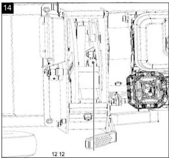
13.2.4 Lubricating the cutter disc bearing (Fig. 14)
Regular lubrication is essential to prevent damage, premature wear and product failure.
Use a commercially-available, lithium saponified multi-purpose grease of class EP2, e.g.:
- Shell Alvania EP2
- Mobilux EP2
- Beacon Q2
The two grease nipples (12) are to be lubricated before each use. Only use a small amount of grease - do not overfill! Press max. one lift of commercially available grease into the grease nipples (12).
To gain access to the inner grease nipple (12), a few steps are necessary.
- Loosen the screws (10e) and push the retaining plate (10d) downwards. Use an open-ended span-ner, size 18.
- Fold the ejection shaft (10) up to gain access to the inner grease nipple (12).
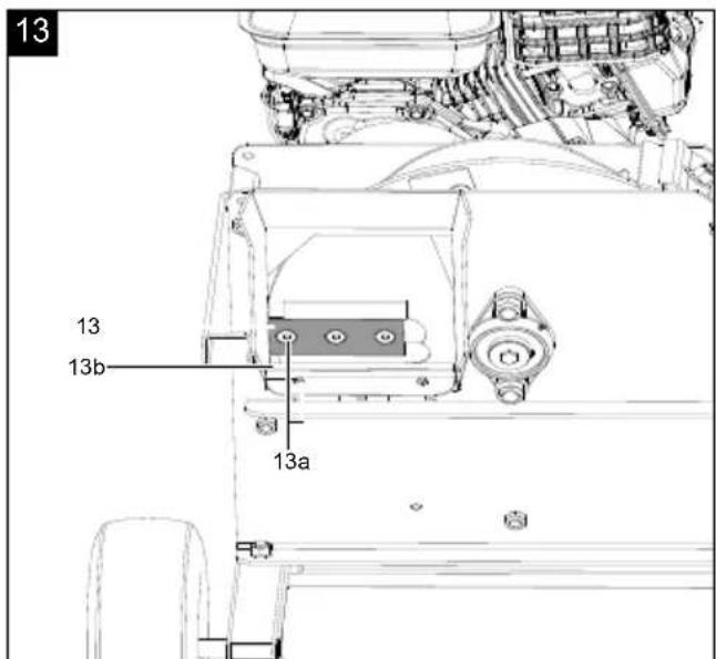
13.2.5 Changing the blade (Fig. 13)
Notes:
- Wear protective gloves when handling the blades!
- Clean the blade and the blade support surface to remove hardened dirt residues. The blades must be positioned exactly during installation.
- When installing, ensure that the blade is touching the stop edge.
If one of the following points occurs after replacing the blade, contact an authorised specialist dealer who can check the product for damage and replace the blades if necessary:
• Not a satisfactory cutting result.
• The product vibrates excessively.
• The product causes unusual noises.
Cutting blade (13)
- Switch off the product and secure it against restart by removing the spark plug connector from the spark plug (17).
- Disassemble the feed hopper (9) to gain access to the cutter disc.
- Move the cutter disc into a similar position as shown. To do this, loosen the three screws (13a) on one of the blades (13).
-
Lock the cutter disc with a wooden wedge or similar aid so it can no longer turn.
-
Loosen the three screws (13a) of the blade (13) and remove the blade (13) carefully. Use an Allen key size 5 and an open-ended spanner size 13.
- Dispose of the used spring washer and self-locking nuts as these cannot be reused after disassembly.
ATTENTION! Only use new spring washers and self-locking nuts for assembly. It must be checked that the cutter disc can move freely after all maintenance work!
- Insert the new blade (13) and secure the blade (13) with the screws (13a).
- Apply a suitable threadlocker to each screw to ensure the required strength and safety.
- Tighten the three screws (13a) evenly with 35-45 Nm. Use an Allen key size 5 and an open-ended spanner size 13.
- Turn the cutter disc in order to replace the second blade (13). Repeat the steps 4 to 9 for the second blade.
- Fit the feed hopper (9) as described in 9.2.
Counter-blade (13b)
- Switch off the product and secure it against restart by removing the spark plug connector from the spark plug (17).
- Disassemble the feed hopper (9) to gain access to the cutter disc.
- Remove the three screws securing the counter-blade (13b). Use an Allen key size 5 and an open-ended spanner size 13.
- Dispose of the used spring washer and self-locking nuts as these cannot be reused after disassembly. ATTENTION! Only use new spring washers and self-locking nuts for assembly. It must be checked that the cutter disc can move freely after all maintenance work!
- Carefully remove the counter-blade (13b).
- Clean the support surface thoroughly.
- Insert the new or cleaned counter-blade (13b) at the intended position.
- Align the counter-blade (13b) so that the following distance is created to the rotating cutting blade: Inner: approx. 3.5 mm Outer: approx. 5.5 mm
- Apply a suitable threadlocker to each screw to ensure the required strength and safety.
- Attach the counter-blade (13b) using the three screws (13a) and tighten them evenly with a torque of 35-45 Nm. Use an Allen key size 5 and an open-ended spanner size 13.
- Fit the feed hopper (9) as described in 9.2.
ATTENTION!
- Ensure that the distance to the cutting blade is set correctly. An incorrect distance can lead to premature wear or malfunctions.
- It must be checked that the cutter disc can move freely after assembly.
13.2.6 Damaged blades
WARNING
There is a risk of injury if you work with a damaged blade.
- Wear protective gloves!
- For safety reasons you should only ever have your blade sharpened and balanced by an authorised specialist workshop. For optimum results it is recommended that the blade should be inspected once a year.
- When changing the blade, only use original spare parts.
If it came into contact with a foreign object. Inspect the product for damage and perform the required repairs before starting again and working with the product. If the product begins to experience exceptionally strong vibrations, switch it off immediately and check it.
Use only blades and accessories recommended by the manufacturer. Use of other insert tools and accessories may result in injury to the user.
In order to avoid an imbalance, sharpening should only be performed by an authorised specialist workshop.
14. Transport
WARNING
Danger of injury and burning!
The product can start unexpectedly and cause injuries.
- Switch off the motor before carrying out any cleaning or maintenance work.
- Allow the motor to cool down.
- Disconnect the spark plug connector from the spark plug.
- The product must be secured against tipping and slipping during transport in vehicles in order to prevent damage and injuries.
- Protect the product from impacts, shocks and severe vibrations, e.g. during vehicular transport.
- In order to move the product, grip the transport handle (8) and tilt the product backwards onto the transport wheels (11).
15. Storage
DANGER
Risk of fire and explosion!
Storing the product near potential sources of ignition can result in a fire or an explosion. This can lead to severe burns or death.
- Eliminate possible sources of ignition, such as furnaces, hot water boilers with gas, gas dryers, etc.
ATTENTION
Risk of damage!
If the product is not stored properly, the engine can be damaged.
- Store the product protected against dirt, dust and moisture.
Store the product and its accessories in a dark, dry and frost-free place that is inaccessible to children.
The optimum storage temperature lies between 5 and 30 °C.
Store the product in its original packaging. Cover the product to protect it from dust or moisture. Store the operating instructions with the product.
15.1 Preparation for storage
If the product will not be used for a period of more than 30 days, the following measures must be taken to prepare it for storage.
WARNING
Do not remove the fuel in enclosed spaces, near fire or when smoking. Petrol fumes can cause explosions and fire.
- Clean and check the product for damage.
- Empty the fuel tank using a petrol extraction pump.
- Start the engine and let it run until the remaining fuel is used up.
- Store fuel in tanks specifically designed for this purpose.
- Change the oil at the end of every season.
- Remove the spark plug connector from the spark plug.
- Store the product in a well-ventilated place or area.
16. Repair & ordering spare parts
After repairs or maintenance, make sure that all safety-related parts are installed and are in perfect condition. All parts which may cause injury must be kept where they are inaccessible to children or others.
Attention: According to the German Product Liability Act, no liability is accepted for damage caused by improper repairs or by not using original spare parts.
Such work should be performed by a customer service centre or an authorised specialist. The same applies to accessory parts.
Spare parts and accessories can be obtained from our Service Centre. To do this, scan the QR code on the front page.
Important note in the case of repairs:
For return delivery of the product for repair, please ensure for safety reasons that it is free of oil and fuel when it is sent to the service centre.
16.1 Ordering spare parts
Please provide the following information when ordering spare parts:
- Model designation
- Item number
- Type plate data
Spare parts / accessories Article no.:
| Cutting blade | 7904401701 |
| Counter-blade | 59 |
16.2 Service information
With this product, it is necessary to note that the following parts are subject to natural or usage-related wear, or that the following parts are required as consumables.
Wearing parts*:
Cutting blades, counter-blade
* may not be included in the scope of delivery!
17. Disposal and recycling
Notes for packaging


The packaging materials are recyclable. Please dispose of packaging in an environmentally friendly manner.
Fuels and oils
- Before disposing of the device, the fuel tank and the engine oil tank must be emptied!
- Fuel and engine oil do not belong in household waste or drains, but must be collected or disposed of separately!
- Empty oil and fuel tanks must be disposed of in an environmentally friendly manner.
04411026
18. Troubleshooting
The following table shows fault symptoms and describes remedial measures in the event of your product failing to work properly. If you cannot localise and rectify the problem with this, please contact your service workshop.
| Fault Possible cause Remedy | ||
| Engine does not start | Spark plug cable not connected | Connect the spark plug cable to the spark plug |
| No fuel or stale fuel Fill with clean, new fuel | ||
| Throttle not in correct start position | Set the throttle to the Start position | |
| Fuel valve closed | Open the fuel valve | |
| Blocked fuel line Clean the fuel line | ||
| Oiled spark plug | Clean the spark plug, set the gap or replace | |
| Not enough engine oil | Check the engine oil level and top it up if necessary | |
| Overfilling the engine | Wait a few minutes before re-starting | |
| Motor runs erratically | Spark plug cable loose | Connect the spark plug cable and secure it |
| Blocked fuel line or stale fuel Clean the fuel line. Fill the fuel tank with clean, new fuel | ||
| Water or contamination in the fuel system | Drain the fuel from the fuel tank. Fill with new fuel | |
| Contaminated air filter | Clean or replace the air filter | |
| Motor overheating | Contaminated air filter Clean the air filter | |
| Restricted airflow Clean the engine and the air inlets | ||
| Oil loss from the engine | Worn seals | Contact specialist dealer |
| Leaks on housing | ||
| Cutter disc does not turn | Engine disengaged | Pull the clutch lever upwards |
| V-belt worn or torn | Contact specialist dealer | |
Günzburger Straße 69
D-89335 Ichenhausen
Cher client,
Günzburger Straße 69
D-89335 Ichenhausen
Bästa kund!
Scheppach GmbH, Günzburger Str. 69, 89335 Ichenhausen
| DE | EU-KonformitätserklärungÜbersetzung der OriginalkonformitätserklärungWir erklären in alleiniger Verantwortung, dass das hier beschriebene Produkt mit den geltenden Richtlinien und Normen übereinstimmt. | Der hier beschriebene Gegenstand der Erklärung erfüllt die Vorschriften der Richtlinie 2011/65/EU des Europäischen Parlaments und des Rates vom 8. Juni 2011 zur Beschränkung der Verwendung bestimmter gefährlicher Stoffe in Elektro- und Elektronikgeräten.*Technische Unterlagen verfügbar bei: ** | ||
| Artikelnummer*** | Artikelbezeichnung: Gartenhäcksler WCP4800 | Marke**** | ||
| GB | EU Declaration of ConformityTranslation of the original Declaration of ConformityWe declare under our sole responsibility that the product described here complies with the applicable directives and standards. | The object of the declaration described here fulfils the regulations of the directive 2011/65/EU of the European Parliament and Council from 8th June 2011, on the restriction of the use of certain hazardous substances in electrical and electronic equipment.*Technical documentation available at: ** | ||
| Item number*** | Item designation: Petrol garden shredde WCP4800 | Brand**** | ||
| FR | Déclaration UE de conformitéTraduction de la déclaration de conformité originaleNous déclarons, sous notre propre responsabilité, que le produit décrit ici est conforme aux directives et normes en vigueur. | L'appareil décrit ci-dessus dans la déclaration est conforme aux réglementations de la directive 2011/65/EU du Parlement Européen et du Conseil du 8 juin 2011 visant à limiter l'utilisation de substances dangereuses dans la fabrication des appareils électriques et électroniques.*Dossier technique auprès de:** | ||
| Référence *** | Désignation de l'article: Broyeur à végétaux thermique WCP4800 | Marque **** | ||
| SE | EU-försäkran om överensstämmelseÖversättning från försäkran om överensstämmelse i originalVi förklarar under eget ansvar att produkten som beskrivs här överensstämmer med gällande riktlinjer och standarder. | Föremålet för försäkran som beskrivs här överensstämmer med bestämmelserna i Europaparlamentets och rädets direktiv 2011/65/EU av den 8 juni 2011 om begränsning av användningen av vissa farliga ämnen i elektriska och elektroniska produkter.*Teknisk dokumentation tillgänglig hos:** | ||
| Artikelnummer *** | Artikelbeteckning: Bensindriven kompostkvarn WCP4800 | Märke **** | ||
| ***5904411903 | ****SCHEPPACH | |||
| **:Stefan HartingerGünzburger Str. 69D-89335 Ichenhauseni.V.Andreas Pecher /Head of Project Managementi.V. Andreas Pecher /Ichenhausen, 05.08.2025 | X 2011/65/EU*X 2014/30/EU□ 2016/1628/EU□ 2014/29/EU□ 2014/35/EU□ 2004/22/EG□ 2014/68/EU□ 89/686/EWG_96/58/EG□ 90/396/EWG | X 2006/42/EG□ Annex IVNotified Body:Notified Body No.:Certificate No.: | X 2000/14/EG; 2005/88/EGNoise:measured L_WA = 106 dBguaranteed L_WA = 109 dBX Annex V□ Annex VINotified Body:Notified Body No.: |
| X 2016/1628/EUEmission No.: e24*2016/1628*2021/1398SRA1/P*0520*00 | |||
| EN ISO 12100:2010; EN 55012:2007+A1:2009; EN ISO 13857:2019 | |||
Garantie DE
Apparent defects must be notified within 8 days from the receipt of the goods. Otherwise, the buyer loses its rights of claim due to such defects are invalidated. We guarantee for our machines in case of proper treatment for the time of the statutory warranty period from delivery in such a way that we replace any machine part free of charge which provably becomes unusable due to faulty material or defects of fabrication within such period of time. With respect to parts not manufactured by us we only warrant insofar as we are entitled to warranty claims against the upstream suppliers. The costs for the installation of the new parts shall be borne by the buyer. The cancellation of sale or the reduction of purchase price as well as any other claims for damages shall be excluded.