GS1500 ATG - Mechanical chipper SCHEPPACH - Free user manual and instructions
Find the device manual for free GS1500 ATG SCHEPPACH in PDF.

| Product type | Petrol garden shredder |
| Brand | Scheppach |
| Model | GS1500 ATG |
| Dimensions (L x W x H) | 2560 x 890 x 1480 mm |
| Weight | 177 kg |
| Max branch diameter | 120 mm |
| Engine type | 4-stroke, 1 cylinder, air-cooled |
| Displacement | 420 cm³ |
| Power | 9 kW / 12 PS |
| Speed | 3600 min⁻¹ |
| Fuel tank capacity | 6.5 L |
| Recommended engine oil | SAE 5W-30 / 10W-30, capacity 1.1 L |
| Spark plug | F7RTC |
| Tire inflation pressure | 0.7 bar |
| Battery | 12 V / 20 Ah, lead-acid |
| Guaranteed sound power level | 119 dB |
| Cutting system | Blade disc with 2 blades and counter-blades |
| Ejection orientation | Adjustable discharge chute with deflector |
| Starting | Electric and manual (cable) |
| Safety devices | Emergency stop, automatic shutdown at low oil level, overload protection |
Frequently Asked Questions - GS1500 ATG SCHEPPACH
User questions about GS1500 ATG SCHEPPACH
0 question about this device. Answer the ones you know or ask your own.
Ask a new question about this device
Download the instructions for your Mechanical chipper in PDF format for free! Find your manual GS1500 ATG - SCHEPPACH and take your electronic device back in hand. On this page are published all the documents necessary for the use of your device. GS1500 ATG by SCHEPPACH.
USER MANUAL GS1500 ATG SCHEPPACH
natural_image
Exterior view of a modern snowman with attached mechanical components and chains (no visible text or symbols)GS1500 ATG
20
27
28
natural_image
Technical line drawing of a tracked vehicle with visible gears and structural components (no text or symbols)29
31
Günzburger Straße 69
D-89335 Ichenhausen
Verehrter Kunde
- 1x Unterlage
-2x Gabelschlüssel SW 8 mm - 1x Gabelschlüssel SW 13 mm
- 1x Gabelschlüssel/Ratschenschlüssel SW 16 mm
- 1x Gabelschlüssel/Ratschenschlüssel SW 17 mm
- 3x Vierkanthölzer
8.1 Montage der Räder (6) (Abb. 1, 4)
Homepage: https://www.scheppach.com/de/service
Explanation of the symbols on the device
Symbols are used in this manual to draw your attention to potential hazards. The safety symbols and the accompanying explanations must be fully understood. The warnings themselves will not rectify a hazard and cannot replace proper accident prevention measures.
 | Attention! Failure to observe the safety signs and warning information affixed to the device and failure to observe the safety and operating manual can result in serious injury or even death. |  | Check the oil level. |
 | Warning - Read the operating manual to reduce the risk of injury. | 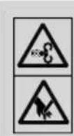 | Danger! Rotating blades.Keep hands and feet outside of the openings when the machine is running. |
 | Wear hearing protection. Excessive noise can result in a loss of hearing. | ||
 | Wear safety goggles. Sparks created during work or fragments, chippings and dust ejected by the device can case sight loss. | 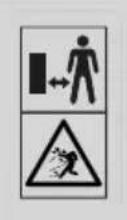 | Make sure that other persons maintain a sufficient safety distance.Keep uninvolved persons away from the device.Hurled objects and rotating parts can cause severe injuries. |
 | Wear sturdy footwear! | ||
 | Wear safety gloves! |  | Important. The exhaust gases are toxic. Do not operate the engine in areas that are not ventilated. |
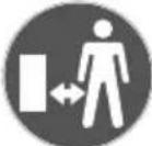 | Make sure that other persons maintain a sufficient safety distance. |  | Protect the device from rain and do not leave outdoors in the rain! |
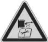 | Remove the spark plug connector prior to all maintenance work. |  | Attention: Risk of injury! Do not reach or climb into the feed hopper or discharge chute during operation. |
 | Attention: hot surface - danger of burning.Removing or modifying protective or safety equipment is prohibited. |  | ATTENTION! Operating materials are flammable and explosive.Naked flames prohibited! Do not refuel while the engine is running! |
 | Important. The exhaust gases are toxic. Do not operate the engine in areas that are not ventilated. |  | Be very careful when handling lubricants! |
 | Weight kg |  | The device complies with the applicable European directives. |
 | Tank contents |  | The device does not have street approval. |
 | Guaranteed sound power level |  | Speed adjustmentHare = fastTortoise = slow |
 | Choke closedFuel valve open |  | Maximum wood diameter 120 mm |
| △ Attention! | We have marked points in these operating instructions that impact your safety with this symbol. | ||
| DANGER! | Signal word to indicate an imminently hazardous situation which, if not avoided, will result in death or serious injury. | ||
| WARNING! | Signal word to indicate a potentially hazardous situation which, if not avoided, could result in death or serious injury. | ||
| CAUTION! | Signal word to indicate a potentially hazardous situation which, if not avoided, could result in minor or moderate injury. | ||
| NOTE | Signal word for marking a potentially hazardous situation which, if not avoided, could result in material damage to the device or property/ possessions. | ||
Table of contents: Page:
- Introduction....38
- Device description (Fig. 1, 2, 20)....38
- Scope of delivery (Fig. 3)....39
- Proper use 39
- Safety instructions 39
- Technical data....42
- Unpacking 42
- Assembly 43
- Before commissioning 44
- Operation....45
- Cleaning....47
- Transport....48
- Maintenance 48
- Storage 53
- Disposal and recycling....55
- Troubleshooting 56
- Declaration of conformity 87
1. Introduction
Manufacturer:
Scheppach GmbH
Günzburger Straße 69
D-89335 Ichenhausen
Dear Customer
We hope your new tool brings you much enjoyment and success.
Note:
In accordance with the applicable product liability laws, the manufacturer of this device assumes no liability for damage to the device or caused by the device arising from:
- Improper handling
- Failure to comply with the operating instructions
• Repairs carried out by third parties, unauthorised specialists.
• Installing and replacing non-original spare parts
• Application other than specified
Note:
Read through the complete text in the operating manual before installing and commissioning the device.
This operating manual should help you to familiarise yourself with your device and to use it for its intended purpose.
The operating manual includes important instructions for safe, proper and economic operation of the device, for avoiding danger, for minimising repair costs and downtimes, and for increasing the reliability and extending the service life of the device.
In addition to the safety instructions in this operating manual, you must also observe the regulations applicable to the operation of the device in your country.
Keep the operating manual at the device, in a plastic sleeve, protected from dirt and moisture. They must be read and carefully observed by all operating personnel before starting the work.
The device may only be used by personnel who have been trained to use it and who have been instructed with respect to the associated hazards. The required minimum age must be observed.
In addition to the safety instructions in this operating manual and the separate regulations of your country, the generally recognised technical rules relating to the operation of identical devices must also be observed.
We accept no liability for accidents or damage that occur due to a failure to observe this manual and the safety instructions.
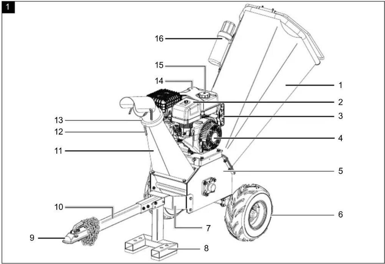
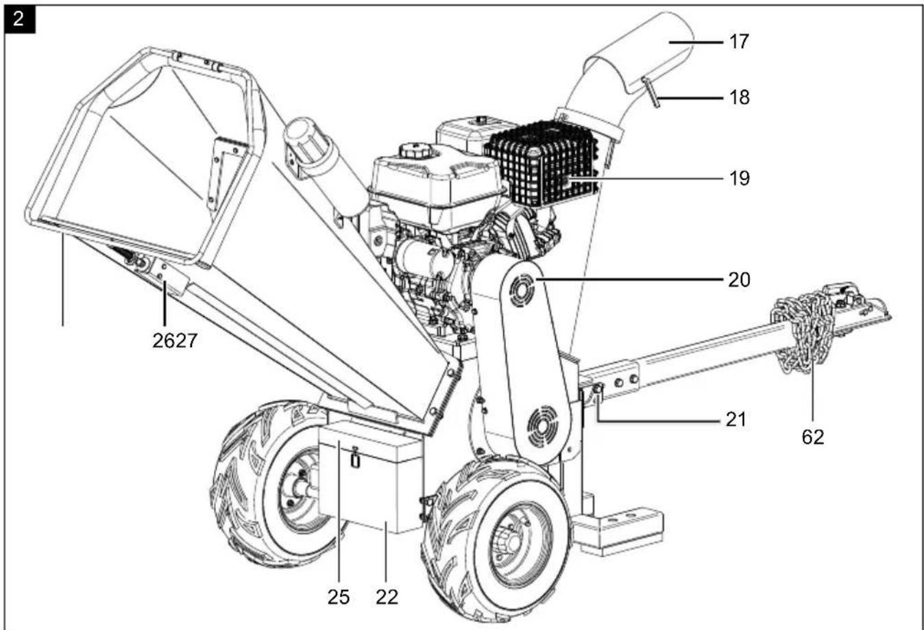
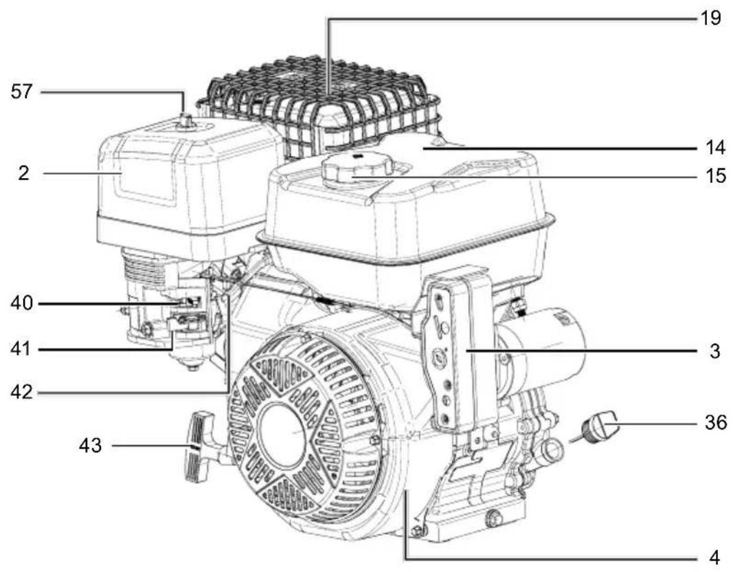
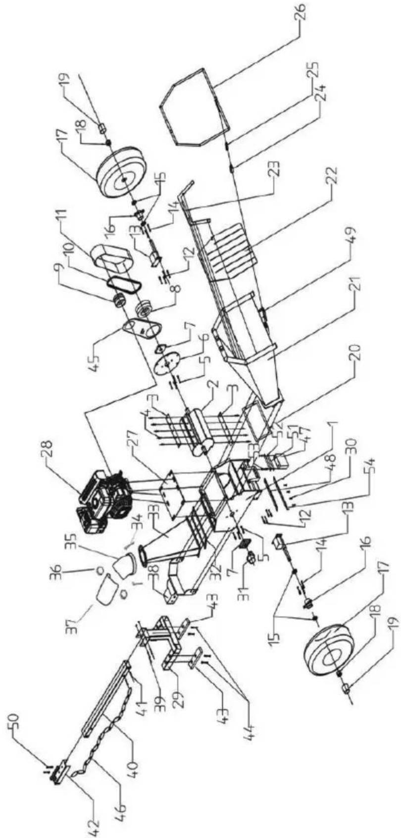
2. Device description (Fig. 1, 2, 20)
- Feed funnel
- Air filter cover
- Operating panel
- Motor
- Shredding unit
- Wheels
- Foot bracket
- Foot
- Ball holder
- Drawbar
- Ejector chamber
- Live ring quick clamp
- Live ring
- Fuel tank
- Tank cover
- Operating manual storage container
- Discharge deflector
- Discharge deflector quick clamp
- Exhaust system
- V-belt cover
- Locking pin
- Battery compartment
- Battery retaining bracket
- Battery
- Battery cover
- Safety switch
- EMERGENCY STOP bow
- Safety switch connection cable
- Engine connection cable
- Off switch
- On switch
- E-starter
- Ignition key
- Ignition lock
- Reset switch
- Oil filler cap with oil dipstick
- Oil drain hose
- Fuel filter insert
- Tyre valve
- Choke lever
- Fuel valve
- Throttle
- Pull starter
- Blade screws
- Cutter disc
- Blade
- Counter-blade
- Counter-blade screws
-
Stop bar
-
Spacer strip
- Set screws
- Lock nut
- Belt tensioning screw
- Lock nut
- Engine/shredding unit connection screws
- V-belt
- Wing screw
- Air filter
- Spark plug connector
- Spark plug
- Bearings
- Grease nipple
- Safety chain
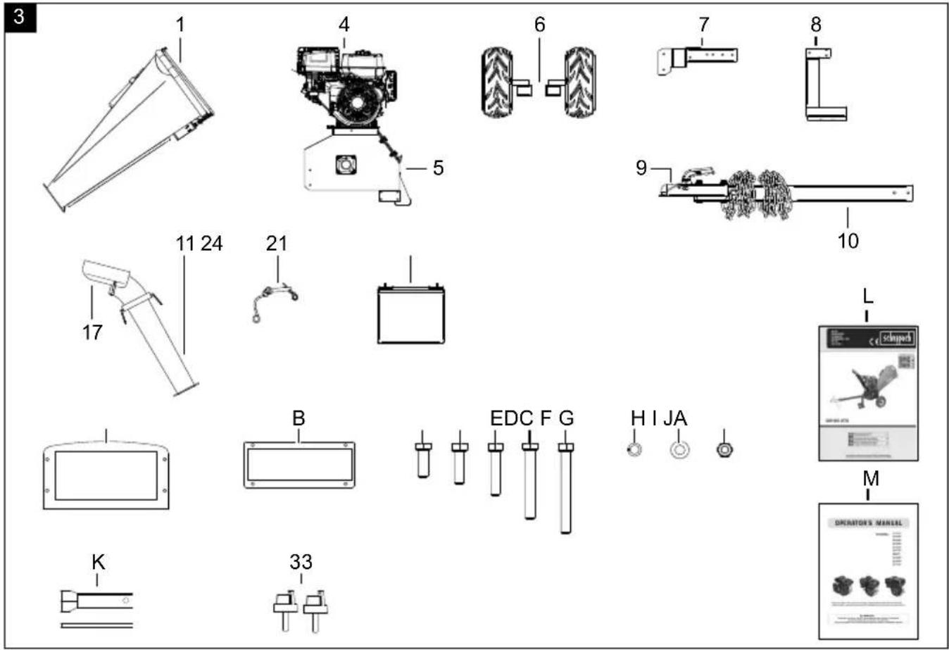
3. Scope of delivery (Fig. 3)
• 1x feed funnel rubber seal (A)
• 1x ejector chamber rubber seal (B)
• 12x M10x25 mm hexagonal bolt (C)
• 4x M10x35 mm hexagonal bolt (D)
• 4x M10x30 mm hexagonal bolt (E)
- 2x M10x70 mm hexagonal bolt (F)
- 1x M10x80 mm hexagonal bolt (G)
• 23x 10.5 mm spring washer (H)
- 23x 10.5 mm washer (I)
• 19x M10 locknut (J)
• 1x Spark plug wrench (K)
• 1x operating manual for petrol blade shredder (L)
• 1x engine operating manual (M)
• 2x ignition keys (33)
4. Proper use
The device is suitable for private use around the home and hobby garden. A device for private gardens and allotments refers to a device with an annual operating time generally not exceeding 50 hours, during which time the device is primarily used to shred organic household and garden waste. Public facilities, sporting halls, and agricultural/forestry applications are excluded.
The device may only be used in the intended manner. Any use beyond this is improper.
Proper use includes shredding
- All types of branches up to a maximum diameter of 120 mm (depending on the type of wood and freshness),
• Hedges and tree cuttings, - Shrubs and bushes,
- Wilting, moist, garden waste that has already been stored for several days, alternating with branches
The user/operator, not the manufacturer, is responsible for damages or injuries of any type resulting from this. An element of the intended use is also the observance of the safety instructions, as well as the assembly instructions and operating information in the operating manual.
Persons who operate and maintain the device must be familiar with the manual and must be informed about potential dangers.
The liability of the manufacturer and resulting damages are excluded in the event of modifications of the device.
The device may only be operated with original parts and original accessories from the manufacturer.
Please note that our equipment was not designed with the intention of use for commercial or industrial purposes. We assume no guarantee if the device is used in commercial or industrial applications, or for equivalent work.
⚠ Attention: The unit does not have road approval and is therefore not intended for use on public roads. It may only be used on cordoned off premises that are fenced in, attached to a vehicle and moved using it.
5. Safety instructions
We have marked points in this operating manual that impact your safety with this symbol. △
Furthermore, the operating manual contains other important text sections that are marked with the word "ATTENTION!".
⚠ Attention!
When using equipment, several safety warnings must be observed to prevent injuries and damage. For this reason, please carefully read this operating manual / safety instructions. If you hand the device over to another person, please hand over this operating manual / safety instructions as well. We accept no liability for accidents or damage that occur due to a failure to observe this manual and the safety instructions.
DANGER
A failure to observe these instructions poses an extreme danger of death or the risk of life-threatening injuries.
WARNING
A failure to observe these instructions poses a danger of death or the risk of serious injuries.
CAUTION
A failure to observe these instructions poses a minor to moderate danger of injury.
NOTE!
A failure to observe these instructions poses a risk of damage to the engine or other property.
Who is not permitted to use the device:
- Children and other people who do are not familiar with the usage instructions (local stipulations may specify a minimum age for users)
• People under the influence of alcohol, drugs and medication, as well as those who are tired or ill.
Handling
- Make sure that all nuts, pins and screws are securely tightened so that the device is kept in a safe working condition.
- Never store the device with petrol in the tank inside a building in which fuel vapours may come into contact with naked flames or sparks.
- Allow the engine to cool down before parking the device in enclosed spaces.
- In order to avoid fire hazards, keep the engine, exhaust system and the area around the fuel tank free of grass, leaves and leaking grease (oil).
- Check the device for signs of wear and loss of functionality.
- For safety reasons, replace worn or damaged parts.
- If the fuel tank has to be drained, you must do this outdoors.
- Do not run the combustion engine in closed rooms in which hazardous carbon monoxide can collect.
- Only shred in daylight or with good artificial lighting.
- Do not use the device in a thunderstorm - risk of lightning strike!
• Always maintain good footing on inclines. - All protective devices and covers must be installed before any work is carried out on the machine.
-
Never use the device if the blade or safety grilles are damaged, or without the attached guards, e.g. deflectors and/or discharge deflector.
-
Do not adjust and overclock the engine speed settings.
- Start the engine with care, in accordance with the manufacturers instructions.
- The device must not be tipped when starting the engine.
- Do not start the engine if you are standing in front of the ejector chamber.
- Never out hands and feet on or under rotating parts. Always keep clear of the ejector chamber.
- Never reach into the filler or ejection opening. The device interior contains moving parts that could possibly pull you into the machine.
- Never lift or transport the device with the engine running.
- Only carry out maintenance work and rectify faults when the engine is switched off.
- Stop the engine and make sure that all moving parts have come to a standstill and that the ignition key, if present, is removed:
- Before you dislodge any blockages or clogs in the ejector chute.
- Before checking or cleaning the device, or performing work on it.
- If the device begins to experience exceptionally strong vibrations, switch it off immediately and check it.
- Any time you leave the device.
- Before you refuel.
- Close the fuel valve after shredding.
- Operating the device at excessive speed can increase the risk of accidents.
- Be careful when adjusting the device and avoid trapping fingers between the moving blade and rigid parts of the device.
- Avoid shredding in places where the wheels have trouble gripping or shredding is unsafe in any other way.
- Watch out for traffic near a road.
- The user must be adequately trained in the use, adjustment and operation of the machine (including prohibited operations).
- Check the device regularly and make sure that all start locks and push buttons are working properly before each use.
-
Please note that improper maintenance, the use of non-compliant spare parts, or the removal or modification of safety devices can result in damage to the device and serious injury to the person working with it.
-
Please note that the device's safety systems or equipment must not be tampered with or deactivated. Never remove any safety-related parts.
- Please note that the user must not change or manipulate any sealed engine speed control settings.
- Use only blades and accessories recommended by the manufacturer. Use of other tools and accessories may result in injury to the user.
• Always keep the device in good operating condition. - It is necessary to take enough breaks to reduce noise and vibration exposure.
- The protective clothing and all accessories used must correspond to the "Personal Protective Equipment" directive.
- Only wear closed, suitable clothing and protective gloves with short, closed, sealing cuffs.
ATTENTION: Use only Super E5 petrol as fuel.
⚠ Use of petrol
⚠ Danger to life! Petrol is toxic and highly flammable.
- Only store petrol in containers (canisters) designed and tested for this purpose. The fuel tank caps must always be properly screwed on and tightened. Defective caps must be replaced for safety reasons.
- Keep petrol away from sparks, open flames, permanent flames, heat sources and other sources of ignition. Do not smoke!
- Refuel outdoors only and do not smoke while refuelling.
- Before refuelling, switch off the combustion engine and let it cool down.
- Petrol must be filled before starting the combustion engine. While the combustion engine is running or if the device is hot, the fuel tank must not be opened and petrol must not be filled.
- Open the tank cover carefully and slowly. Wait for the pressure to equalise and only then remove the tank cover completely.
- Use a suitable funnel or filler pipe for refuelling so that no fuel can spill onto the combustion engine and housing or lawn.
Do not overfill the fuel tank!
• To leave room for the fuel to expand, never fill the fuel tank beyond the lower edge of the filling nozzle. Observe additional information in the combustion engine user manual.
- If petrol has overflowed, do not start the combustion engine until the petrol-contaminated area has been cleaned. Avoid starting the engine until the fuel vapours have evaporated (wipe dry).
• Always wipe up spilled fuel immediately.
• If petrol has got on clothing, it must be changed.
- The tank cover must be properly screwed on and tightened after each refuelling operation. The device must not be put into operation without the original tank cover screwed on.
- For safety reasons, check the fuel line, fuel tank, tank cover and connections regularly for damage, ageing (brittleness), tight fit and leaks, and replace if necessary.
- Only empty the fuel tank outdoors.
- Never use beverage bottles or similar to dispose of or store operating materials such as fuel. People, especially children, could be tempted to drink from it.
- Only use the device outdoors and never in closed or poorly ventilated rooms.
- Never store the device with petrol in the fuel tank inside a building. Any fuel vapours produced can come into contact with naked flames or sparks and ignite.
- Do not place the device and fuel tank near heaters, radiant heaters, welding machines or other sources of heat.
Risk of explosion!
If a defect is detected on the fuel tank, the tank cover or on fuel-carrying parts (fuel lines) during operation, the combustion engine must be switched off immediately. Then consult a specialist dealer.
Battery safety
- To avoid spark formation due to a short circuit, always disconnect the negative cable (−) from the battery first and reconnect it last.
- Never smoke during any work on the battery. Always keep sparks, naked flames and other heat sources away from the battery.
- Special care must be taken when using jumper cables. Follow relevant instructions to avoid damage to the device (in particular, do not operate the starter for more than 10 seconds).
- Never open the battery and do not drop it.
• Always charge the battery in a closed room with good ventilation, dry and protected against the weather. - Do not short-circuit battery connections.
-
Deformed or defective (leaking) batteries must not be used and must be replaced and disposed of in an environmentally friendly manner. Observe the country-specific regulations.
-
If the batteries are defective, liquid may leak out. Avoid contact! In case of accidental contact, rinse with water. If the liquid gets into your eyes, seek additional medical attention. Leaking battery fluid can cause skin irritation, burns and chemical burns.
- Regularly visually inspect the connection cables on the battery for damage. Have damaged cables replaced by a specialist.
- Never bypass the fuses. Never use a fuse with a rating other than the prescribed rating (amperes).
Residual risks
The electric tool has been built according to state-of-the-art and the recognised technical safety rules. However, individual residual risks can arise during operation.
• Health hazard due to electrical power, with the use of improper electrical connection cables.
• Furthermore, despite all precautions having been met, some non-obvious residual risks may still remain.
- Residual risks can be minimised if the "Safety information" and the "Proper use" together with the operating manual as a whole are observed.
- Avoid accidental start-ups of the device.
- Use the device in the way that is recommended in this operating manual. This is how to ensure that the device provides optimum performance.
- Technical data
| Dimensions L x W x H mm | 2560x890x1480 |
| Infeed height mm | 1260 |
| Ejection height mm | 1140 |
| Infeed opening max. mm | 480x440 |
| Ejection opening max. mm | 120 |
| Wheel ø mm | 420 |
| Weight kg 177 | |
| Branch thickness max ø mm | 120 |
| Cutter disc ø mm 233 | |
| Blade mm | 300 x 55 x 5 |
| Counter-blade mm | 300 x 51 x 15 |
| Type of engine | 4-stroke 1 cylinder air-cooled |
| Displacement 420 cm3 | |
| Rotation speed 3600 rpm |
| Power 9 kW / 12PS | |
| Fuel Super E5 | |
| Tank contents 6.5 l | |
| Engine oil | SAE 5W-30 / 10W-30 |
| Tank capacity / oil 1.1 l | |
| Spark plug F7RTC | |
| Tyre pressure 0.7 bar | |
| Battery type Lead acid battery | |
| Battery rated voltage 12 V | |
| Battery capacity 20AH | |
Technical changes reserved!
Noise & vibration
⚠ Warning: Noise can have serious effects on your health. If the device noise exceeds 85 dB, please wear suitable hearing protection.
Noise data
Information about the noise level measured in accordance with applicable standards (EN ISO 3744:1995, ISO 11094:1991):
| Sound power level (measured) L_WA | 116 dB |
| Uncertainty K_WA | 3 dB |
| Sound pressure level L_pA | 96 dB |
| Uncertainty K_pA | 3 dB |
| Sound power level L_WA (guaranteed) 119 dB | |
Wear hearing protection.
Excessive noise can result in a loss of hearing.
7. Unpacking
- Open the packaging and carefully remove the device.
- Remove the packaging material, as well as the packaging and transport safety devices (if present).
- Check whether the scope of delivery is complete.
- Check the device and accessory parts for transport damage. In the event of complaints the carrier must be informed immediately. Later claims will not be recognised.
- If possible, keep the packaging until the expiry of the warranty period.
- Familiarise yourself with the device by means of the operating manual before using for the first time.
- With accessories as well as wearing parts and spare parts use only original parts. Spare parts can be obtained from your specialist dealer.
- When ordering, please provide our article number, the type and year of manufacture for your device.
⚠ DANGER!
The device and the packaging are not children's toys!
Do not let children play with plastic bags, films or small parts! There is a danger of choking or suffocating!
8. Assembly
ATTENTION!
Always make sure the device is fully assembled before commissioning!
⚠ Attention! Due to the heavy device weight, we recommend assembly by at least three people.
Tools required (not included in the scope of delivery):
- 1x pad
- 2x open-ended spanner, size 8 mm
- 1x open-ended spanner, size 13 mm
- 1x open-ended spanner/ratchet spanner, size 16 mm
- 1x open-end wrench/ratchet spanner SW 17 mm
- 3x square timbers
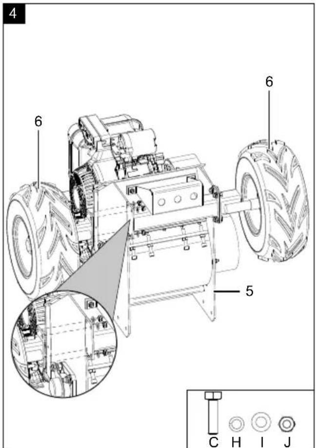
8.1 Fitting the wheels (6) (Fig. 1, 4)
-
Place a pad on the floor to avoid damage to the device.
-
Carefully remove the device from the pallet with two other people.
-
Tilt the shredding unit (5) forward slightly.
-
Fit the wheels (6) by aligning the fitting holes on the wheels (6) with the fitting holes on the shredding unit (5) and secure with four hexagonal bolts (C), spring washers (H), washers (I) and locknuts (J) each. Use a 16 mm open-ended spanner/ratchet spanner to fit the hexagonal bolts (C) and a 17 mm open-ended spanner/ratchet spanner for the locknuts (J). Ensure that the locknuts (J) are on the inside.
NOTE! When mounting, pay attention to the running direction of the wheels (6).
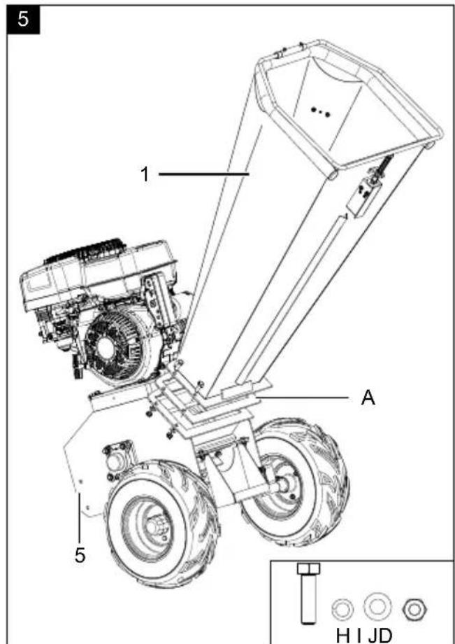
8.2 Fitting the feed funnel (1) (Fig. 2, 5, 6)
-
Now place the chopping unit (5) backwards on the wheels (6).
-
Position the feed funnel (1) with the feed funnel rubber seal (A) over the shredding unit (5) and ensure that the fitting holes are aligned.
- Screw the feed funnel (1) tight to the shredding unit (5) using four hexagonal bolts (D), spring washers (H), washers (I) and two locknuts (J). Use a 16 mm open-ended spanner/ratchet spanner to fit the hexagonal bolts (D) and a 17 mm open-ended spanner/ratchet spanner for the locknuts (J).
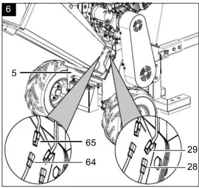
- In order to activate the EMERGENCY STOP bow (27), connect the safety switch connection cable (28) for the safety switch (26) to the engine connection cable (29).
- Connect the safety switch disconnector cable (64) to the engine connection cable (65).
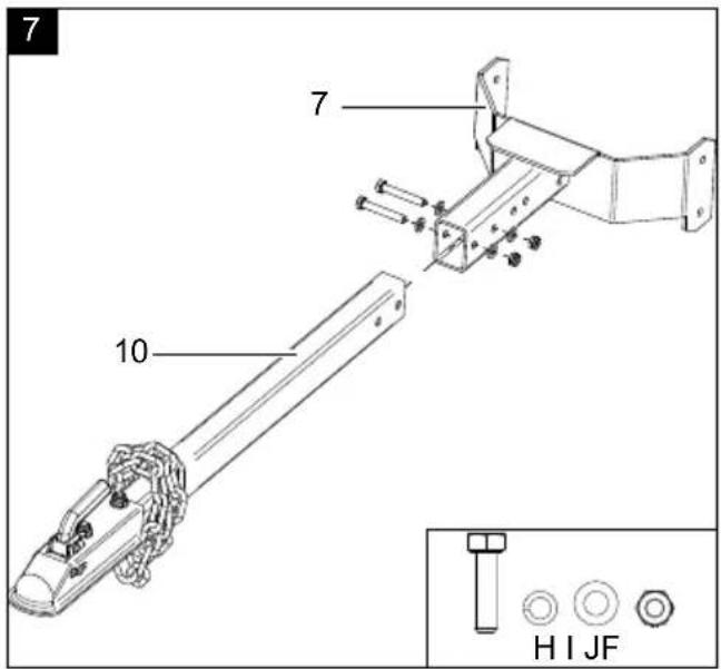
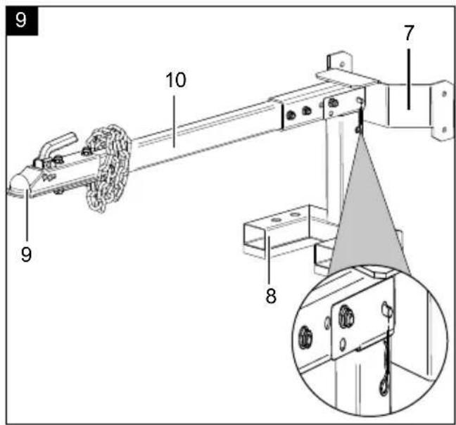
8.3 Mounting the foot (8) (Fig. 7-9)
- Connect the drawbar (10) to the foot bracket (7) by pushing the drawbar (10) into the foot bracket recess (7) until the fitting holes are aligned.
- Attach the drawbar (10) to the foot bracket (7) using two hexagonal bolts (F), spring washers (H), washers (I) and locknuts (J). Use a 16 mm open-ended spanner/ratchet spanner to fit the hexagonal bolts (F) and a 17 mm open-ended spanner/ratchet spanner for the locknuts (J).
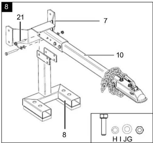
- Place the foot bracket (7) on the foot (8) and position the fitting holes so that they are aligned.
- Screw the foot (8) to the foot bracket (7) using the hexagonal bolt (G), the spring washer (H), the locking lug on the locking pin (21), the washer (I) and the locknut (J). Use a 16 mm open-ended spanner/ratchet spanner to fit the hexagonal bolts (G) and a 17 mm open-ended spanner/ratchet spanner for the locknuts (J). Ensure that you also install the locking lug on the locking pin (21)!
- Unfold the foot (8) and secure it with the locking pin (21).
- Grip the device on the feed funnel (1) and tilt it forwards until it is on the foot (8).
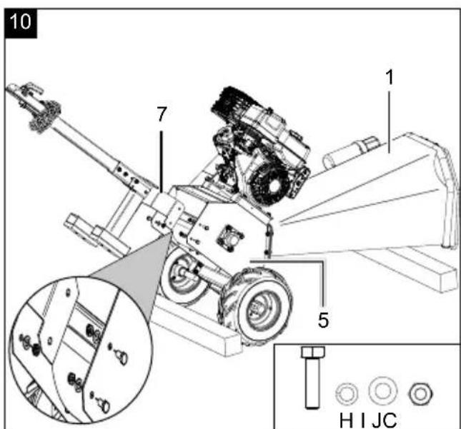
8.4 Installing the drawbar (10) on the shredding unit (5) (Fig. 10)
- Place two pieces of square timber in front of and behind the wheels (6) so that the device does not roll away when tilting.
- Place another piece of square timber (approx. 10 cm thick around 1 m away from the shredding unit (5)) on the floor.
- Grip the device on the feed funnel (1) and tilt it backwards until it is on the square timber.
⚠ Attention! Ensure that you do not damage the EMERGENCY STOP bow (27)!
- Screw the foot bracket (7) tight to the shredding unit (5) using four hexagonal bolts (C), spring washers (H), washers (I) and locknuts (J) each. Use a 16 mm open-ended spanner/ratchet spanner to fit the hexagonal bolts (C) and a 17 mm open-ended spanner/ratchet spanner for the locknuts (J).
- Grip the device on the feed funnel (1) and tilt it forwards until it is on the foot (8).
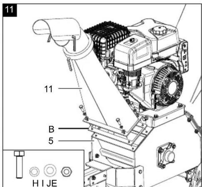
8.5 Installing the ejector chamber (11) (Fig. 11)
- Position the ejector chamber (11) with the ejector chamber rubber seal (B) over the shredding unit (5) and ensure that the fitting holes are aligned.
- Screw the ejector chamber (11) tight to the shredding unit (5) using four hexagonal bolts (E), spring washers (H), washers (I) and two locknuts (J). Use a 16 mm open-ended spanner/ratchet spanner to fit the hexagonal bolts (E) and a 17 mm open-ended spanner/ratchet spanner for the locknuts (J).
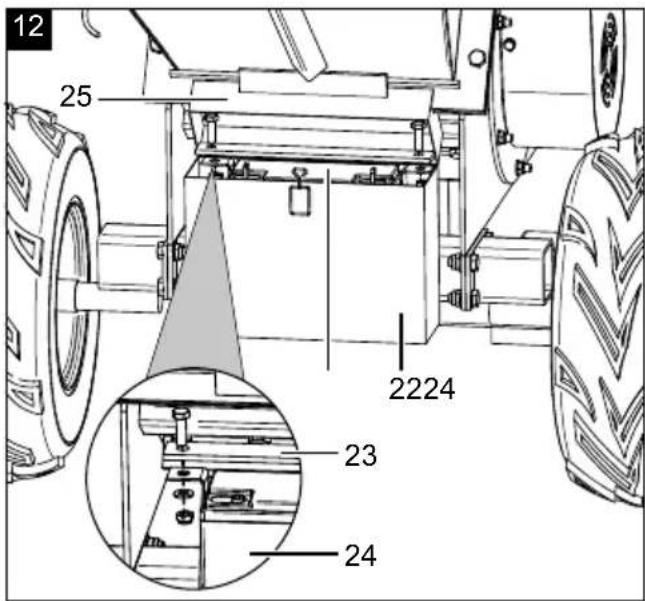
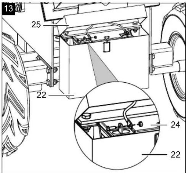
8.6 Fitting the battery (24) (Fig. 12-13)
- Use the locking mechanism to open the battery cover (25).
- In order to remove the battery retaining bracket (23), loosen the two hexagonal bolts using a 13 mm open-ended spanner.
- Insert the battery (24) into the battery compartment (22) and secure it by attaching the battery retaining bracket (23) using the two hexagonal bolts.
- Use two 8 mm open-ended spanners to connect the battery (24).
- Then connect the red cable to the positive pole (+) and the black cable to the negative pole (-).
- Close the battery cover (25) again.
Attention!
Danger of short circuit!
- To avoid a short circuit, always disconnect the negative cable (-) from the battery (24) first and reconnect it last.
- When connecting/disconnecting the battery (24), ensure that the poles (+/-) do not touch each other and/or the frame.
9. Before commissioning
ATTENTION!
Always make sure the device is fully assembled before commissioning!
WARNING!
Health hazard!
Inhalation of petrol/lubricating oil vapours and exhaust gases can cause serious damage to health, unconsciousness and in extreme cases death.
- Do not breathe petrol/lubricating oil vapours and exhaust gases.
- Operate the device outdoors only.
NOTE!
Product damage
Using the device without or with too little engine and gearbox oil can result in engine damage.
- Fill with petrol and oil before commissioning. The device is supplied without engine and gearbox oil.
NOTE!
Environmental damage!
Spilled oil can pollute the environment permanently. The liquid is highly toxic and can quickly lead to water pollution.
- Fill/empty oil only on level, paved surfaces.
- Use a filling nozzle or funnel.
- Collect drained oil in a suitable container.
- Wipe up spilled oil carefully immediately and dispose of the cloth according to local regulations.
- Dispose of oil as per local regulations.
NOTE!
Risk of damage!
If incorrectly stored or undrained fuel is used, the carburettor may become clogged or engine operation may be affected.
- Put unused fuel in an airtight vessel and store it in a dark, cool room.
Tools required (not included in the scope of delivery):
- Oil filling cylinder
- Funnel
- Standard foot pump
9.1 Topping up oil (Fig. 14-15)
⚠ Attention!
The device is delivered without engine oil. Therefore, ensure that you add oil before starting it up. Use SAE 5W-30/10W-30 oil.
Note:
Check the oil level regularly before commissioning. An oil level that is too low can damage the engine.
- Place the device on a level, even surface.
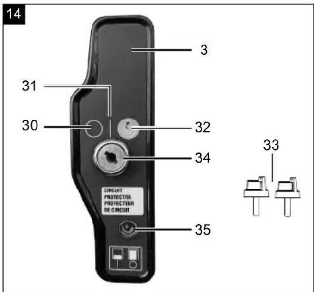
-
Remove the ignition key (33) from the ignition lock (34).
-
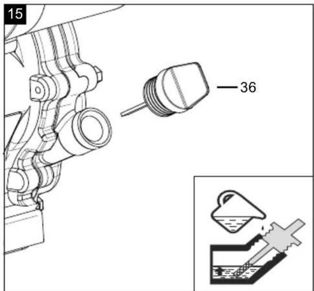
Unscrew the oil filler cap with oil dipstick (36).
- Use an oil filling bottle to top up the engine oil. Note the max. filling capacity of 1.1 l. Fill the oil up to the lower edge of the filling nozzle carefully.
- Wipe the oil filler cap with oil dipstick (36) with a clean, lint-free cloth.
- Screw the oil filler cap with oil dipstick (36) back into the filling nozzle until it reaches the stop.
- Unscrew the oil filler cap with oil dipstick (36) and read the oil level in the horizontal position. The oil level must be between L (low) and H (high) on the oil filler cap with oil dipstick (36).
- If the oil level is too low, repeat the process.
- Then screw the oil filler cap with oil dipstick (36) back on.
9.2 Filling in fuel (Fig. 16)
Attention!
The device is delivered without petrol. It is therefore essential to fill with petrol before commissioning. Use Super E5 petrol for this.
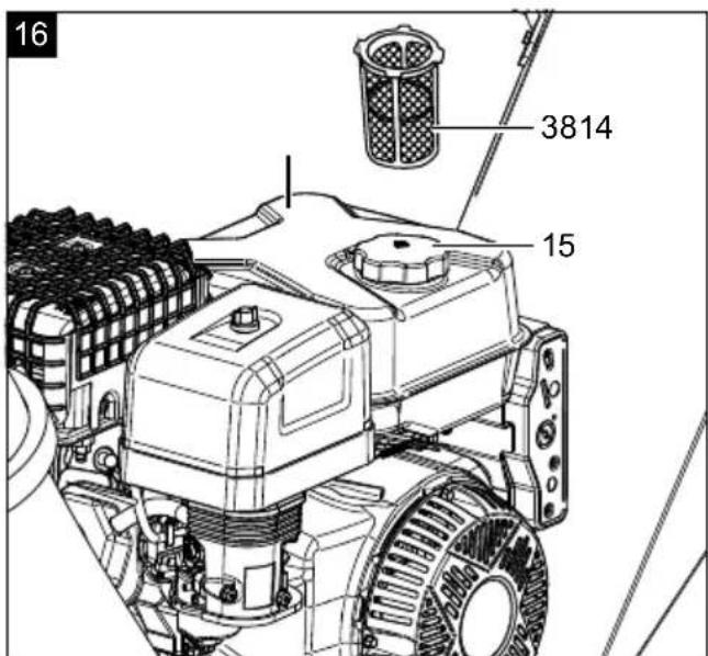
- Unscrew the tank cover (15).
- Using a suitable funnel, fill with a maximum of 6.5 litres of Super E5 petrol into the fuel tank (14).
-
Ensure that the fuel tank (14) is not overfilled and that no petrol is spilled. Always use the fuel filter insert (38). Wipe up spilled petrol immediately and wait until the fuel vapours have evaporated (danger of ignition).
-
Retighten the tank cover (15).
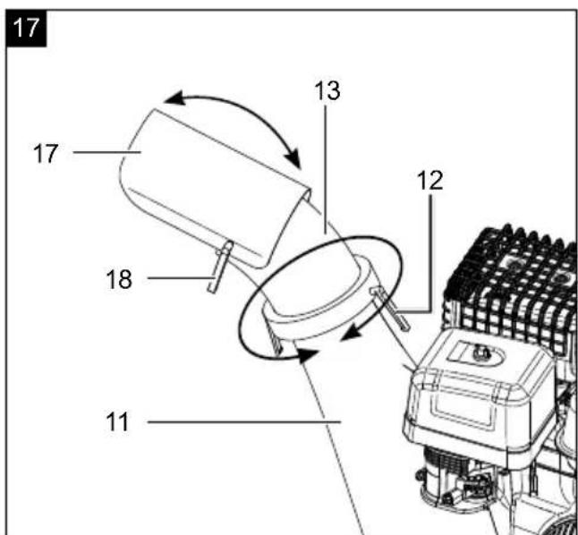
9.3 Adjusting the ejector chamber (11) (Fig. 17)
Note: The ejector chamber (11) can be adjusted using the live ring (13) and the discharge deflector (17).
-
To adjust the live ring (13), loosen the live ring quick clamp (12). Then set the required position and re-tighten the live ring quick clamp (12).
-
To adjust the discharge deflector (17), loosen the quick clamp on the discharge deflector (18). Then set the required position and re-tighten the quick clamp on the discharge deflector (18).
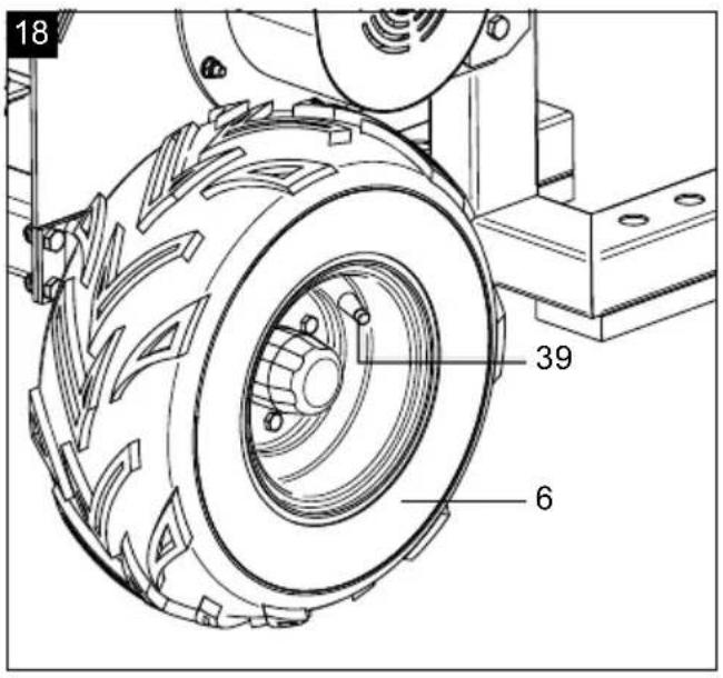
9.4 Check the tyre pressure on the tyres (6) (Fig. 18)
Note: The correct tyre pressure is the essential prerequisite for a perfectly balanced device.
-
Check the tyre pressure with a commercially available foot pump at regular intervals.
-
If necessary, use a standard foot pump to top up with air by first removing the tyre valve cap (39). The correct tyre pressure on the tyres (6) is 0.7 bar.
Note: If you notice that the tyres or wheels (6) are damaged, please contact customer service or a specialist workshop.
10. Operation
ATTENTION!
Always make sure the device is fully assembled before commissioning!
ATTENTION!
Always check whether the feed funnel is empty and that the blades are not blocked prior to starting the engine!
⚠️ ATTENTION! Always check that the emergency stop bar switches off properly before chopping.
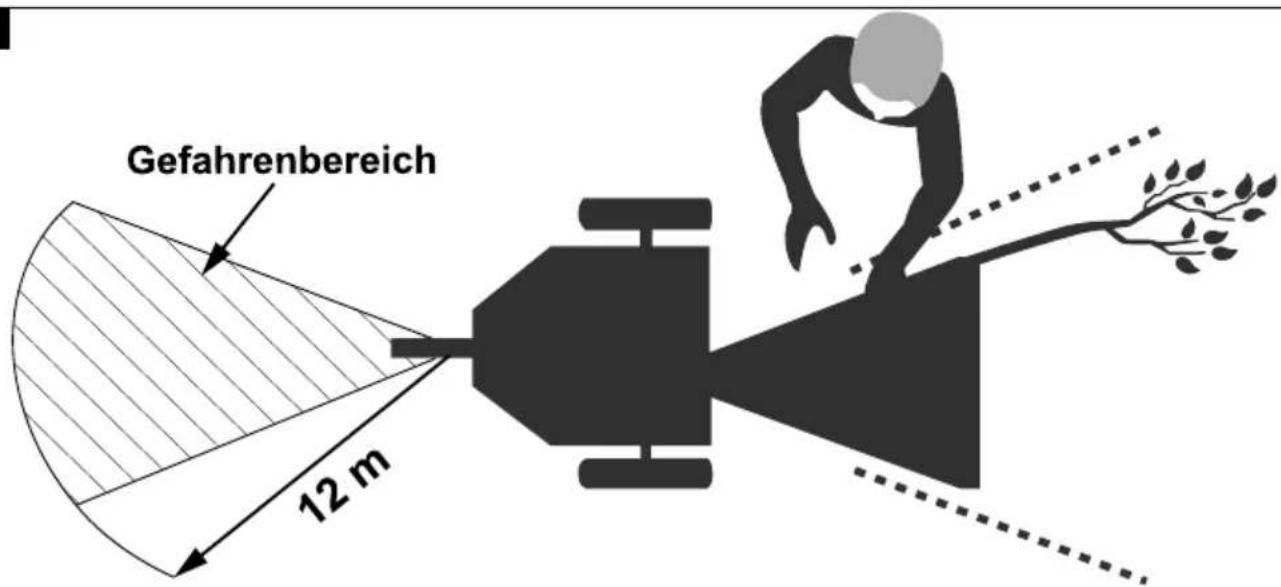
⚠️ ATTENTION! It is forbidden to stay in the driving area of the shredder when starting and operating it.
ATTENTION!
Check the safety equipment regularly before each start-up. Faulty safety equipment can cause serious injuries!
Working instructions
Good work results require well sharpened blades.
Note:
Blunt blades reduce the cutting performance and impair the work process! Sure signs of blunt blades are leaving an indentation, reduced performance and a poor cutting pattern.
Feeding the chopped material
Always switch the engine off first!
- Only wear closed, suitable clothing and protective gloves with short, closed, sealing cuffs.
• Always stand to the side of the filling funnel when feeding chopped material (Fig. 31). - Stake out an area at least 3 m wide and 12 m long on the side of the ejector. Check the working area prior to starting. Pay particular attention to children, other people and animals (Fig. 31).
• Make sure that you have secure footing and always maintain your balance. Do not lean forwards. - Stand at the same level as the device when inserting the chopped material.
-
Stay a safe distance from the ejector area in order to avoid being hit by chopped material or parts being ejected.
-
Pay attention to stones and soil when collecting the material to be cut.
- Earth causes the blades to wear very quickly and should therefore be removed from the material to be shredded
- Foreign objects (such as nails, wire, ropes or climbing aids) must be removed from the material to be shredded.
- Hard objects such as stones, glass, metal and similar objects must not be thrown into the device.
- Do not throw roots with soil attached to them into the device.
- Wood such as tree cuttings, etc. requires well sharpened blades and should be crushed separately to maintain as long a service life as possible for the blades.
- The cutting unit draws the chopped material in virtually automatically.
- Insert branches with the thickest end first and place on the part of the cutter disc that rotates downwards if possible (kick-back).
- Remove side shoots from branches with many smaller branches.
- Freshly-cut wood requires less force meaning that sections with larger cross sections can be shredded.
- Processing dry material at the end is beneficial. The moisture in the device is absorbed and the housing cleaned.
- If the cutting unit gets blocked, switch the engine off immediately to avoid an engine overload. Rectify the fault before switching the engine back on.
- Do not let the pile of shredded material in the vicinity of the ejection opening get too high. This can result in shredded material blocking the ejector chute. This can cause the material to kick-back through the filling opening.
- Note: Remove residual waste from the device after finishing work. Attention: Remove spark plug cap and ignition key!
- The shredding unit (5) must be free of shredded material residues in order to restart it after work breaks.
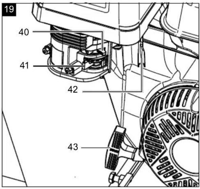
10.1 Starting the engine (4) (Fig. 19)
⚠ Attention! Danger of poisoning!
- Only use the device outdoors and never in closed or poorly ventilated rooms.
Speeds
Use the throttle lever (42) to set the engine to the desired speed.
- MIN position, "tortoise"
- MAX position, "hare"
Note:
- The E-starter (32) or the pull starter (43) can be used to start the engine (4) (Fig. 1, 14, 19).
10.2 Start the engine (4) with the electric starter (32) (Fig. 1, 14, 19, 20).
- Set both the choke lever (40) and the fuel valve (41) on the engine (4) to "ON".
- Position the throttle (42) in the middle.
- Insert the ignition key (33) into the ignition (34).
- Turn the ignition key (33) to the right position, "E-starter" (32) and hold it in this position until the device starts up.
- Let the engine (4) warm up for several seconds.
- Turn the choke lever (40) to the "OFF" position slowly.
- Use the throttle to set the required speed (42).
- If the engine (4) does not start even after several attempts, start the device as described in section 10.3.
- The choke is not normally required when restarting a warm motor.
10.3 Using the pull starter (43) to start the engine (4) (Fig. 1, 14, 19, 20)
Attention! Never allow the pull starter (43) to whip back. This can result in damage.
- Set both the choke lever (40) and the fuel valve (41) on the engine to "ON".
- Position the throttle (42) in the middle.
- Insert the ignition key (33) into the ignition (34).
- Turn the ignition key (33) to the middle position, "Switch on" (31).
- Now pull the pull starter (43) slowly several times so that fuel can flow from the fuel tank (14) to the engine (4).
-
Start the engine (4) by pulling the pull starter (43) quickly. If the engine (4) does not start, repeat the process.
-
Let the engine (4) warm up for several seconds.
-
Turn the choke lever (40) to the "OFF" position slowly.
-
Use the throttle to set the required speed (42).
-
If the engine (4) does not start even after several attempts, read the "Troubleshooting" chapter.
-
The choke is not normally required when restarting a warm motor.
Note: If the device's battery (24) is empty, the engine (4) can only be started using the pull starter (43).
If the battery (24) is deeply discharged, proceed as described in sections 14.2 and 14.3.
10.4 Switching the engine (4) off
(Fig. 1, 14, 19, 20)
Note: Allow the device to run for a short time (approx. 30 seconds) switching it off so that the engine (4) can cool down.
- Use the throttle (42) to set the speed to MIN, "tortoise".
- Turn the ignition key (33) to the "Switch off" position, (30).
- Remove the ignition key (33) and store it in a safe place.
- Set the fuel valve (41) to the "OFF" position.
Note: You can only remove the ignition key (33) when the "Switch off" position (30) is selected.
△ ATTENTION! In order to switch the device off in the event of an emergency, actuate the EMERGENCY STOP bow (27) by pressing the EMERGENCY STOP bow (27) against the safety switch (26).
△ ATTENTION! Even after the EMERGENCY STOP bow (27) has been actuated, the blades (46) continue to rotate for a few seconds, depending on the speed set.
Note: Do not use the EMERGENCY STOP bow (27) routinely to stop the device.
10.5 Overload protection (Fig. 1, 14)
The device is equipped with overload protection. If the engine is overloaded, this switches off automatically to protect the device from overheating.
-
If the overload protection has triggered, switch the device off and wait until the engine (4) has cooled down.
-
Now press the reset switch (35) on the control panel (3) and switch the device on again.
10.6 Automatic oil cut-off
The automatic oil cut-off system responds when there is too little engine oil.
-
If the oil level is too low, top up the oil as described in 9.1.
-
Start the engine (4) as described in 10.1.
11. Cleaning
Danger!
Always shut the engine down and remove the spark plug connector and ignition key before carrying out any cleaning work.
⚠ Attention! Never use a high-pressure cleaner to clean your machine.
The use of high-pressure cleaners shortens the service life and reduces the ease of maintenance.
- Keep protective devices, air vents and the motor housing as free of dust and dirt as possible. Rub the device clean with a clean cloth or blow it off with compressed air at low pressure.
• We recommend that you clean the device directly after every use. - Clean the device at regular intervals using a damp cloth and a little soft soap. Do not use any cleaning products or solvents; they could attack the plastic parts of the device. Make sure that no water can penetrate the device interior. Water entering a power tool will increase the risk of electric shock.
Tools required (not included in the scope of delivery):
- Open-ended spanner, size 10 mm
- Open-ended spanner/ratchet spanner, size 16 mm
- Open-ended spanner/ratchet spanner, size 17 mm
- Brush or compressed air
11.1 Cleaning the V-belts (56) (Fig. 2, 14, 25, 28)
- Place the device on a level, even surface.
- Remove the ignition key (33) from the ignition lock (34).
- Remove the spark plug connector (59) from the spark plug (60).
- Remove the V-belt cover (20) by unscrewing the four hexagonal bolts using a 10 mm open-ended spanner.
- Clean the transmission elements and the two V-belts (56) once to twice per year using a brush or compressed air.
- Re-attach the V-belt cover (20) and secure it with four hexagonal bolts.
11.2 Removing blockages and shredded material residues from the cutter disc (45)
(Fig. 2, 5, 14, 29)
Switch the machine off to rectify faults or to remove jammed pieces of wood.
- Place the device on a level, even surface.
- Remove the ignition key (33) from the ignition lock (34).
- Remove the spark plug connector (59) from the spark plug (60).
-
Disconnect the safety switch connection cable (28) and the engine connection cable (29).
-
Disconnect the connection of the safety switch disconnector cable (64) and the engine connection cable (65).
- Disassemble the feed funnel (1) and the ejector chamber (11) and remove the feed funnel rubber seal (A) and the ejector chamber rubber seal (B). Use a 16 mm open-ended spanner/ratchet spanner to fit the hexagonal bolts (C) and a 17 mm open-ended spanner/ratchet spanner for the locknuts (J).
- Clean inside the device and the cutter disc (45) with compressed air in order to remove shredded material residues.
- Fit the feed funnel (1) and the ejector chamber (11) with the feed funnel rubber seal (A) and the ejector chamber rubber seal (B).
12. Transport
Tools required (not included in the scope of delivery):
- Petrol extraction pump
- Suitable vehicle
12.1 Preparing for transport (Fig. 14, 16, 20, 28, 29)
- Empty the fuel tank (14) using a petrol extraction pump (see section 13.7).
Warning: Do not remove the petrol in enclosed spaces, near fire or when smoking. Petrol fumes can cause explosions and fire. - The ignition key (33) must always be removed from the ignition lock (34) and stored securely to prevent unauthorised or improper use by children and other persons.
- Remove the spark plug connector (59) from the spark plug (60).
- Clean the device.
12.2 Transporting without vehicle (Fig. 1, 9)
⚠ Attention: If the unit is to be transported, the engine must be switched off and the spark plug connector disconnected.
- In order to move the device, grip the ball holder (9) and tilt the device backwards.
- You can now transport the device.
12.3 Transporting with a vehicle (Fig. 8-9)
⚠ Attention: The unit does not have road approval and is therefore not intended for use on public roads. The device may only be used on cordoned off premises that are fenced in, attached to a vehicle and moved using it.
- In order to move the device with a vehicle, you must fold the foot (8) in.
- Loosen the safety cotter pin on the locking pin (21) and pull the locking pin (21) out.
- Fold the foot (8) up.
- Attach the locking pin (21) to the lock in order to secure the foot (8). This prevents it falling down. Secure the locking pin (21) with the safety cotter pin.
- Attach the ball holder (9) to the trailer coupling on a suitable vehicle.
- Take the securing chain (63) and hang it on the trailer hitch. The securing chain (63) serves as an additional securing connection should the ball mount (9) become detached from the trailer hitch.
Note: Ensure that the lock on the ball holder (9) latches into place.
13. Maintenance
⚠ WARNING!
In the event that the user is to perform maintenance and service work, the user must possess the necessary technical skills.
If the device is shut down for maintenance, inspection or storage, turn off the engine, disconnect the spark plug connector from the spark plug, remove the ignition key from the ignition and ensure that all rotating parts have stopped.
⚠ Attention!
To ensure that the motor (4) is no longer running, carry out a visual inspection.
A two-colour pulley can be seen under the belt cover (20). This must no longer rotate!
All protective and safety equipment must be reassembled immediately after repair, maintenance is completed.
Secure the device to prevent an inadvertent start-up before carrying out maintenance and/or servicing work:
- Switch off the engine (4) before carrying out any cleaning or maintenance work.
- Allow the engine (4) to cool down.
- Remove the spark plug connector (59) from the spark plug (60). Also remove the ignition key (33) from the ignition (34).
- Regular, careful servicing is required to guarantee the safety level and performance of the device.
- Make sure that all nuts, pins and screws are securely tightened so that the device is in a safe working condition.
- Check the device regularly for signs of wear and loss of functionality.
- For safety reasons, replace worn or damaged parts.
- Use only original spare parts.
- Check that the wheels (6) are secured.
- Any work not described in this operating manual must be performed by an authorised specialist workshop only.
Tools required (not included in the scope of delivery):
- Open-ended spanner, size 10 mm
- Open-ended spanner/ratchet spanner, size 16 mm
- Open-ended spanner/ratchet spanner, size 17 mm
- Allen key 10
- Feeler gauge
- Copper wire brush
- Grease gun
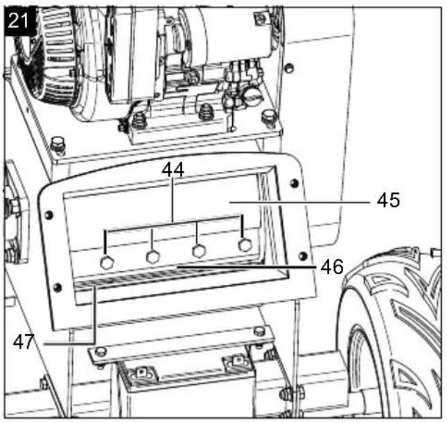
13.1 Changing the blade (46)
(Fig. 5, 6, 14, 21, 23, 28)
⚠ Attention! Wear protective gloves when handling the blades!
- Place the device on a level, even surface.
- Remove the ignition key (33) from the ignition lock (34).
- Remove the spark plug connector (59) from the spark plug (60).
- Disconnect the safety switch connection cable (28) and the engine connection cable (29).
- Disconnect the connection of the safety switch disconnector cable (64) and the engine connection cable (65).
- Disassemble the feed funnel (1) and the ejector chamber (11) and remove the feed funnel rubber seal (A) and the ejector chamber rubber seal (B). Use a 16 mm open-ended spanner/ratchet spanner to fit the hexagonal bolts (C) and a 17 mm open-ended spanner/ratchet spanner for the locknuts (J).
- Turn the cutter disc (45) so that the blade screws (44) are well accessible.
- Use a 16 mm open-ended spanner/ratchet spanner with extension to loosen the blade screws (44) on the blade (46) and remove the blade (46) carefully.
- Insert the new blade (46) and secure the blade (46) with the blade screws (44).
Note: Clean the blade (46) and the blade support surface on the cutter disc (45) to remove hardened dirt residues. The blades (46) must be positioned exactly during installation.
⚠ Attention: To prevent the blade screws (44) from loosening by themselves, they must be glued in place with a medium-strength screw glue.
- Turn the cutter disc (45) in order to replace the second blade (46). Proceed as described in point 7 above to do this.
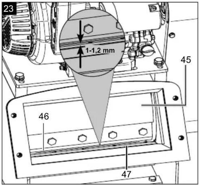
- Once you have replaced both blades (46), check and, if necessary, adjust the gap between the blades (46) and the counter-blades (47) (see section 13.4). This should normally be 1 - 1.2 mm.
- Fit the feed funnel (1) as described in section 8.2.
Note: If one of the following points occurs after replacing the blade, contact an authorised specialist dealer who can check the counter-blade (47) for damage and replace it if necessary:
• Not a satisfactory cutting result.
• The device vibrates excessively.
• The device causes unusual noises.
• The counter-blade (47) is damaged.
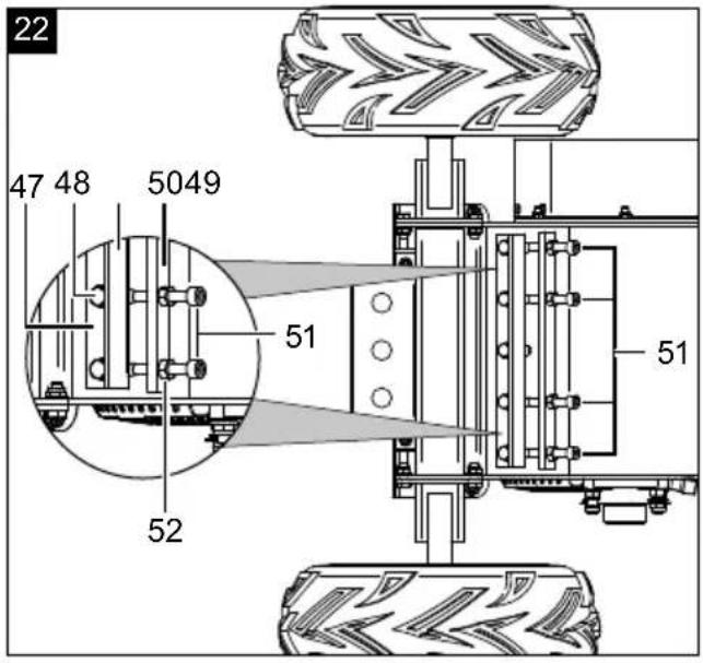
13.2 Adjusting the counter-blade (47)
(Fig. 5, 6, 17, 18, 21, 22, 23, 28)
⚠ Attention! Wear protective gloves when handling the blades!
- Place the device on a level, even surface.
- Remove the ignition key (33) from the ignition lock (34).
- Remove the spark plug connector (59) from the spark plug (60).
- Disconnect the safety switch connection cable (28) and the engine connection cable (29).
- Disconnect the connection of the safety switch disconnector cable (64) and the engine connection cable (65).
- Disassemble the feed funnel (1) and the ejector chamber (11) and remove the feed funnel rubber seal (A) and the ejector chamber rubber seal (B). Use a 16 mm open-ended spanner/ratchet spanner to fit the hexagonal bolts (C) and a 17 mm open-ended spanner/ratchet spanner for the locknuts (J).
- Loosen the counter-blade screws (48) on the counter-blade (47) (underside).
Note: Do not remove the counter-blade screws (48) completely.
-
Loosen the set screws (51) and the counternuts (52) from the spacer strip (50) in order to adjust the gap between the blade (46) and the counter-blade (47). Use a size 10 Allen key and a 16 mm open-ended spanner/ratchet spanner with an extension to do this. Do not remove the screws completely.
-
Use the four set screws (51) to adjust the tolerance gap to the stop bar (49) and lock the set screws (51) with one counternut (52) each against the spacer strip (50).
Note: The tolerance gap of 1 - 1.2 mm must be adjusted using a feeler gauge on the top of the blade (46) and on the counter-blade (47).
-
Tighten the counter-blade screws (48) on the underside. Ensure that the stop bar (49) is touching the four set screws (51).
-
Use a feeler gauge to check the tolerance gap on the blade (46) and on the counter-blade (47) once again.
-
Fit the feed funnel (1) as described in section 8.2.
Note: The counter-blade (47) is hardened. This increases the service life of the counter-blade (47). As the counter-blade (47) can be turned, this includes the option to use both sides.
13.3 Damaged blades (46)
- If the blade (46) comes into contact with an obstruction despite all precautions, shut down the engine (4) immediately and remove the spark plug connector (59) from the spark plug (60).
- Disconnect the safety switch connection cable (28) and the engine connection cable (29).
- Disconnect the connection of the safety switch disconnector cable (64) and the engine connection cable (65), and remove the feed funnel (1) in order to check the blade (46) for damage.
- Damaged or bent blades (46) must be replaced.
- Never attempt to bend a bent blade (46) back to straight again.
- Never work with bent or heavily worn blades (46), as this will cause vibrations and can lead to further damage to the device.
⚠ Attention! There is a risk of injury if you work with a damaged blade.
13.4 Sharpening the blades (46)
In order to avoid imbalance, the blade should be re-sharpened by an authorised service workshop.
Note: The counter-blade (47) cannot be sharpened, as otherwise, the gap between the blade (46) and the counter-blade (47) can no longer be maintained.
13.5 Checking the oil level (Fig. 15)
⚠ WARNING!
Health hazard!
Inhaling petrol/lubricant vapours may lead to severe health damage, loss of consciousness and, in extreme cases, to death.
- Do not inhale petrol/lubricant vapours.
- Operate the device outdoors only.
NOTE!
Device damage
Using the device without or with too little engine and gearbox oil can result in engine damage.
- Fill with petrol and oil before commissioning. The device is supplied without engine and gearbox oil.
- Only use Super E5 petrol.
- Only use SAE 5W-30/10W-30 engine oil.
NOTE!
Environmental damage!
Spilled oil can pollute the environment permanently. The liquid is highly toxic and can quickly lead to water pollution.
- Fill/empty oil only on level, paved surfaces.
- Use a filling nozzle or funnel.
- Collect drained oil in a suitable container.
- Wipe up spilled oil carefully immediately and dispose of the cloth according to local regulations.
- Dispose of oil as per local regulations.
- Place the device on a level, even surface.
- Remove the ignition key (33) from the ignition lock (34).
- Remove the spark plug connector (59) from the spark plug (60).
- Unscrew the oil filler cap with oil dipstick (36).
- Wipe the oil filler cap with oil dipstick (36) with a clean, lint-free cloth.
- Screw the oil filler cap with oil dipstick (36) back into the filling nozzle until it reaches the stop.
- Unscrew the oil filler cap with oil dipstick (36) and read the oil level in the horizontal position. The oil level must be between L (low) and H (high) on the oil filler cap with oil dipstick (36).
-
If the oil level is too low, top up the oil as described in section 9.1.
-
Then screw the oil filler cap with oil dipstick (36) back on.
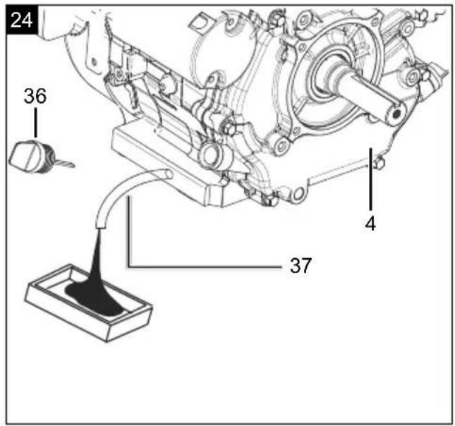
13.6 Changing oil (Fig. 14, 15, 28)
Change the engine oil after the first 50 operating hours.
The engine oil change should be carried out while the motor (4) is at operating temperature.
- Place the device on a level, even surface.
- Remove the ignition key (33) from the ignition lock (34).
-
Remove the spark plug connector (59) from the spark plug (60).
-
Unscrew the oil filler cap with oil dipstick (36).
-
Have a suitable collection container to hand.
-
Unscrew the cover cap from the oil drain hose (37). Hold the oil drain hose (37) over the collection container and allow the oil to run out.
-
Close the oil drain hose (37) again once the oil has drained completely.
-
Fill up with new SAE 5W-30/10W-30 engine oil (approx. 1.1 l).
-
Wipe the oil filler cap with oil dipstick (36) with a clean, lint-free cloth.
-
Screw the oil filler cap with oil dipstick (36) back into the filling nozzle until it reaches the stop.
-
Unscrew the oil filler cap with oil dipstick (36) and read the oil level in the horizontal position. The oil level must be between L (low) and H (high) on the oil filler cap with oil dipstick (36).
-
If the oil level is too low, top up the oil as described in section 9.1.
-
Dispose of the used oil properly.
Dispose of the used oil in accordance with applicable regulations.
13.7 Draining petrol using a petrol extraction pump (Fig. 14, 16, 20)
In case of storage over a longer period of time, the petrol must be drained.
- Place the device on a level, even surface.
- Remove the ignition key (33) from the ignition lock (34).
- Remove the spark plug connector (59) from the spark plug (60).
- Hold a collection container under the hose on the petrol extraction pump.
- Unscrew and remove the tank cover (15).
-
Remove the fuel filter insert (38).
-
Push the petrol extraction pump's hose into the fuel tank (14) and drain the petrol completely using the petrol extraction pump.
-
Reinsert the fuel filter insert (38).
-
Retighten the tank cover (15).
13.8 Cleaning the fuel filter insert (38) (Fig. 16)
Note: The fuel filter insert (38) is a filter cup which is located directly under the tank cover (15) and filters all the fuel filled in.
- Unscrew the tank cover (15).
- Remove the fuel filter insert (38). Clean it in a non-flammable solvent or a solvent with a high flash point.
- Reinsert the fuel filter insert (38).
- Retighten the tank cover (15).
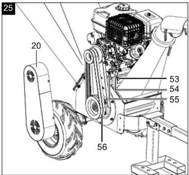
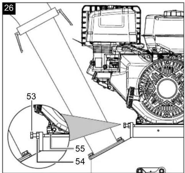
13.9 Tensioning the V-belts (56) (Fig. 14, 25, 26, 28)
Note: The V-belt (56) must be re-tensioned after 5 operating hours.
- Place the device on a level, even surface.
- Remove the ignition key (33) from the ignition lock (34).
- Remove the spark plug connector (59) from the spark plug (60).
- Remove the V-belt cover (20) by removing the four hexagonal bolts using a 10 mm open-ended spanner.
-
Check the V-belts (56) by pressing with your thumb. If it gives by more than 10-15 mm, the V-belts (56) must be re-tensioned.
-
In order to tension the V-belts (56), loosen each of the V-belt tensioning screws (53) and counternuts (54) using a 16 mm open-ended spanner/ratchet spanner with an extension on both sides of the engine (4).
-
Use a 16 mm open-ended spanner/ratchet spanner with extension to loosen the four engine/shredding unit connection screws (55).
-
Use the two belt tensioning screws (53) to re-tension the V-belts (56).
-
Check the V-belts (56) by pressing with your thumb. If the V-belts (56) give by more than 10-15 mm, the V-belts (56) must be re-tensioned.
-
Lock the two belt tensioning screws (53) with one counternut (54) each.
-
Tighten the four engine/shredding unit connection screws (55).
-
Re-attach the V-belt cover (20) and secure it with four hexagonal bolts.
13.10 Replacing the V-belts (56) (Fig. 14, 25, 26, 28)
Note: If the V-belts (56) are torn, worn out or smooth, they must be replaced.
- Place the device on a level, even surface.
- Remove the ignition key (33) from the ignition lock (34).
-
Remove the spark plug connector (59) from the spark plug (60).
-
Remove the V-belt cover (20) by removing the four hexagonal bolts using a 10 mm open-ended spanner.
-
In order to replace the V-belts (56), loosen each of the V-belt tensioning screws (53) and counternuts (54) using a 16 mm open-ended spanner/ratchet spanner with an extension on both sides of the engine (4).
-
Use a 16 mm open-ended spanner/ratchet spanner with extension to loosen the four engine/shredding unit connection screws (55).
-
Remove the old V-belts (56).
-
Pull the V-belts (56) on correctly.
(Pay attention to the running direction!)
- Tension the V-belt (56) as described in section 13.8.
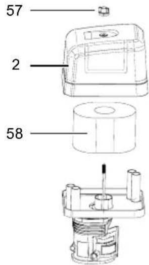
13.11 Air filter maintenance (58) (Fig. 27)
⚠️ DANGER!
Risk of fire and explosion!
If not cleaned correctly, fuel may ignite and even explode. This can lead to severe burns or death.
- Clean the air filter only by knocking it out.
- Never use petrol or flammable solvents to clean the air filter.
NOTE!
Risk of damage!
Operating the engine without the filter element in place can cause engine damage.
- Never run the engine without the air filter element in place.
Contaminated air filters (58) diminish the engine output due to reduced air supply to the carburettor. Regular inspection is therefore essential.
The air filter (58) should be checked every 25 operating hours and cleaned as required. The air filter (58) must be checked more often if the air is very dusty.
- Remove the air filter cover (2) by removing the wing screw (57).
- Remove the air filter (58).
-
Clean the air filter (58) only by tapping it.
-
Replace a faulty air filter (58) with a new one.
- Re-insert the air filter (58) and use the wing screw (57) to fit the air filter cover (2).
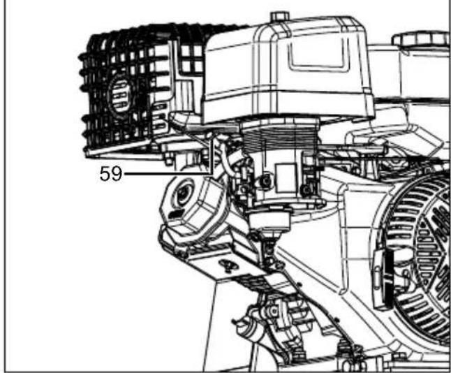
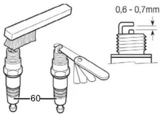
13.12 Spark plug maintenance (60) (Fig. 28-29)
Check the spark plug (60) for contamination for the first time after 20 operating hours and clean it with a copper wire brush if necessary. Then maintain the spark plug (60) every 50 operating hours.
- Place the device on a level, even surface.
- Remove the ignition key (33) from the ignition lock (34).
- Remove the spark plug connector (59) from the spark plug (60).
-
Use the spark plug wrench (K) to remove the spark plug (60).
-
Remove any dirt from the base of the spark plug (60).
-
Visually inspect the spark plug (60). Remove any deposits present using a copper wire brush.
-
Check the spark plug gap. Use a feeler gauge to adjust the electrode gap to 0.6-0.7 mm.
-
Replace the spark plug (60) and take care not to tighten it too firmly.
-
Then place the spark plug connector (59) on the spark plug (60).
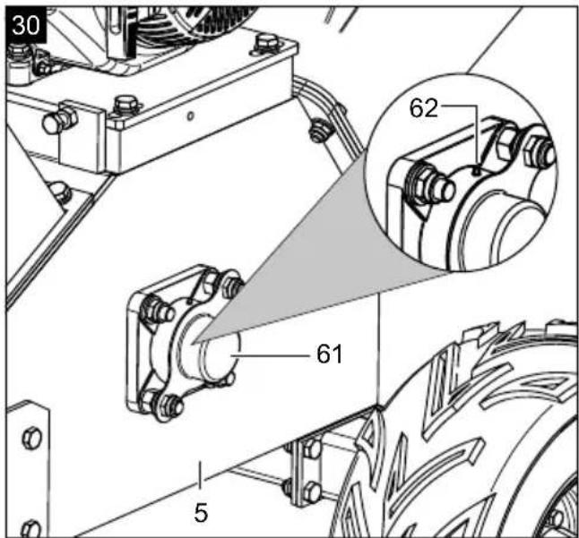
13.13 Lubricating the bearings (61) (Fig. 25, 30)
Note: The bearings (61) on both sides of the chopper unit (5) must be lubricated regularly with a grease gun.
- Place the device on a level, even surface.
- Remove the ignition key (33) from the ignition lock (34).
- Remove the spark plug connector (59) from the spark plug (60).
-
Remove the V-belt cover (20) by removing the four hexagonal bolts using a 10 mm open-ended spanner.
-
Remove the protective caps from the grease nipples (62) on both sides.
-
Use a lint-free cloth to clean the grease nipples (62) on both sides.
-
Use 1-2 pumps of the grease nipples (62) to lubricate the bearings (61) on both sides.
-
Use a lint-free cloth to clean the grease nipples (62) on both sides to remove excess grease.
-
Fit the protective caps to the grease nipples (62) on both sides.
-
Re-attach the V-belt cover (20) and secure it with four hexagonal bolts.
14. Storage
DANGER!
Risk of fire and explosion!
When storing the device in the vicinity of possible sources of ignition, a fire or explosion may occur. This can lead to severe burns or death.
- Eliminate possible sources of ignition, such as furnaces, hot water boilers with gas, gas dryers, etc.
NOTE!
Risk of damage!
If the device is not stored properly, this can result in engine damage.
- Store the device so that it is protected from dirt, dust and moisture.
Tools required (not included in the scope of delivery):
- Petrol extraction pump
- Oil filling cylinder
- Open-end spanner 8 mm
- Open-end spanner 13 mm
- Battery car charger
14.1 Preparation for storage
If the device will not be used for a period of more than 30 days, the following measures must be taken to prepare it for storage.
⚠ Warning information: Do not remove the petrol in enclosed spaces, near fire or when smoking.
Petrol fumes can cause explosions and fire.
- Empty the fuel tank (14) using a petrol extraction pump.
- Start the engine (4) and let it run until the remaining petrol is used up.
- Change the oil at the end of every season. To do this, remove the old engine oil from the warm engine and fill with new (see section 13.5).
- Remove the spark plug connector (59) from the spark plug (60).
- Fill the cylinder with approx. 20 ml of oil from an oil filling bottle.
- Pull the pull starter (43) slowly so that the oil protects the inside of the cylinder.
- Be sure to clean the entire device to protect the paint.
- Store the device in a well-ventilated place or area.
-
Store the device and its accessories in a dark, dry and frost-free place that is inaccessible to children. The optimum storage temperature lies between 5 and 30 °C.
-
Store the power tool in its original packaging. Cover the power tool to protect it from dust or moisture. Store the operating manual with the power tool.
14.2 Removing the battery (24) (Fig. 12-13)
- Use the locking mechanism to open the battery cover (25).
- Disconnect the battery (24).
- To do this, remove the red cable from the positive terminal (+) and the black cable from the negative terminal (-).
- In order to remove the battery retaining bracket (23), loosen the two hexagonal bolts using a 13 mm open-ended spanner.
- Remove the battery (24) from the battery compartment (22).
- Use the two hexagonal bolts to re-tighten the battery retaining bracket (23).
- Close the battery cover (25) again.
Ensure that battery (24) is secured to prevent unauthorised use (e.g. by children).
Charge the battery (24) during the winter 1-2 times to ensure that the full charging capacity is maintained. Incorrect storage can damage the battery (24) and voids the guarantee.
14.3 Charge battery (24) with a car battery charger (Fig. 1, 14)
⚠ DANGER!
Danger due to charging the battery incorrectly! If the charging voltage is too high, there is a risk of the battery (24) exploding.
Always remove the ignition key (33) from the ignition (34) when working on the battery (24).
- The charging current of the charging unit must not exceed 5 A and the charging voltage must not exceed 14.4 V.
- Remove the battery (24) as described in Section 14.2.
- Connect the battery (24) to a car battery charger designed for this purpose. Connect the black cable to the negative terminal (-) and the red cable to the positive terminal (+) of the charging unit.
- Charge the battery (24) for at least 5 hours.
Attention!
Danger of short circuit!
- To avoid a short circuit, always disconnect the negative cable (-) from the battery (24) first and reconnect it last.
- When connecting/disconnecting the battery (24), ensure that the poles (+/-) do not touch each other and/or the frame.
14.4 Maintenance plan
| Task: | Before every use | After 5 operating hours | Every 25 operating hours | Every 50 operating hours | Annually or every 100 operating hours |
| Refuel and check the oil level x | |||||
| Replace the oil x x x | |||||
| Replace the petrol x | |||||
| Clean / replace the petrol filling funnel x | |||||
| Clean the air filter (58) x x | |||||
| Replace the air filter (58) x | |||||
| Inspect the spark plug (60) and the spark plug connector (59) | x | x | |||
| Replace the spark plug (60) x | |||||
| Clean the spark plug (60) x | |||||
| Inspect the device for damage and to ensure it is functioning | x | ||||
| Inspect the V-belts (56) x | |||||
| Re-tension the V-belts (56) x | |||||
| Inspect the blades/counter-blades (46/47) | x | ||||
| Lubricate the bearings (61) | x | ||||
| Check the tyre pressure | x | ||||
| Inspect the exhaust system (19) | x x | ||||
| Re-tighten all screws | x | ||||
| Check that the EMERGENCY STOP bow (27) is functioning | x | ||||
| Lubricate knife drum | x |
If the cutter disc (45) comes into contact with a foreign object and the device subsequently makes unusual noises or vibrates excessively, switch the device off immediately and wait until the cutter disc (45) has stopped. Pull the spark plug connector (59) out to prevent inadvertent activation. Then perform the following steps.
- Check the device for damage
• Repair or replace damaged parts - Check whether all screws are tight and re-tighten if necessary.
Repairs
After any repair or maintenance work, make sure that all safety-related parts are in place and in perfect condition. All parts which may cause injury must be kept where they are inaccessible to children or others.
Attention: According to the German product liability act, no liability is accepted for damage caused by improper repairs or by not using original spare parts. Such work should be performed by a customer service centre or an authorised specialist. The same applies to accessory parts.
Important note in the case of repairs:
When returning the device for repair, please ensure for safety reasons that it is free of oil and petrol when it is sent to the service centre.
Operating times
Please comply with statutory regulations to petrol garden shredders operating times, which may vary from location to location.
Ordering spare parts
Please provide the following information when ordering replacement parts:
- Device type
• Device article number
Service information
With this device, it is necessary to note that the following parts are subject to natural or usage-related wear, or that the following parts are required as consumables.
Wearing parts*: Spark plug, air filter, blade, counter-blade, V-belt
* may not be included in the scope of delivery!
Spare parts and accessories can be obtained from our service centre. To do this, scan the QR code on the cover page.
15. Disposal and recycling
Notes for packaging


The packaging materials are recyclable. Please dispose of packaging in an environmentally friendly manner.
Information on the German Battery Act (BattG)

Used batteries and rechargeable batteries do not belong in household waste, but should be collected and disposed of separately.
- For safe removal of batteries or rechargeable batteries from the electrical appliance and for information on their type or chemical system, follow the further information within the operating or installation instructions.
- Owners or users of batteries and rechargeable batteries are obliged by law to return them after use. Return is limited to the handover of customary household quantities.
- Used batteries can contain harmful substances or heavy metals that can cause damage to the environment and human health. Reuse of the used batteries and use of the resources contained therein contributes to the protection of these two essential commodities.
- The symbol of the crossed-through rubbish bin means that batteries and rechargeable batteries may not be disposed of in household rubbish.
- In addition, if the symbol Hg, Cd or Pb appears under the rubbish bin, this stands for the following:
- Hg: Battery contains more than 0.0005 % mercury
- Cd: Battery contains more than 0.002 % cadmium
- Pb: Battery contains more than 0.004 % lead
- Rechargeable batteries and batteries can be handed in at the following places at no charge:
- Public disposal or collection points (e.g. municipal works yards)
- Points of sale of batteries and rechargeable batteries
- Disposal points of the common take-back system for the used batteries of appliances
- Disposal point of the manufacturer (if not a member of the common take-back system)
- These statements apply only to rechargeable batteries and batteries that are sold in the countries of the European Union and that are subject to European Directive 2006/66/EU. Different provisions can apply to the disposal of rechargeable batteries and batteries in countries outside the European Union.
Contact your local refuse disposal authority for more details of how to dispose of your worn-out electrical devices.
Fuels and oils
- Before disposing of the device, the fuel tank and the engine oil tank must be emptied!
- Fuel and engine oil do not belong in household waste or drains, but must be collected or disposed of separately!
- Empty oil and fuel tanks must be disposed of in an environmentally friendly manner.
16. Troubleshooting
The following table shows fault symptoms and describes remedial measures in the event of your device fails to work properly. If you cannot localise and rectify the problem with this, please contact your service workshop.
| Fault Possible cause Remedy | ||
| The engine (4) does not start. | The spark plug connector (59) is disconnected. | Connect the spark plug connector (59) to the spark plug (60) properly. |
| The fuel is off or stale. Fill with new fuel. | ||
| The throttle (42) is not in the correct start position. | Move the throttle (42) to the start position. | |
| The choke lever (40) is not in the “ON” position. | The choke lever (40) must be in the “ON” position for a cold start. | |
| The fuel line is blocked. Clean the fuel line. | ||
| Sooty spark plug (60). Clean, set gap or replace. | ||
| Too much fuel inside the combustion chamber. | Wait a few minutes before restarting. Do not prime. | |
| The engine (4) splutters. | The spark plug connector (59) is loose. Connect the spark plug connector (59) to the spark plug (60) properly. | |
| The choke lever (40) is in the “ON” position. Set the choke lever (40) to the “OFF” position. | ||
| The fuel line is blocked or the fuel is stale. Clean the fuel line. Fill the fuel tank (14) with new fuel. | ||
| The air filter (58) is clogged. Clean or replace the air filter (58). | ||
| There is water or dirt in the fuel system. Empty the fuel tank (14). Fill with new fuel. | ||
| The air filter (58) is dirty. | Clean or replace the air filter (58). | |
| The carburettor is not adjusted correctly. | See the engine manual. | |
| The engine (4) is over-heating. | The oil level in the engine (4) is too low. Add the correct oil to the engine (4). | |
| The air filter (58) is dirty. Clean or replace the air filter (58). | ||
| The carburettor is not adjusted correctly. See the engine manual. | ||
| Power decreases, poor cutting performance. | The blade (46) is blunt or used up. Sharpening the blade (46) or replace it completely. | |
| Heavy vibrations / loud noises. | The blade screws/counter-blade screws (44/48) are loose. | Tighten the blade screws/counter-blade screws (44/48). |
| Blades/counter-blades (46/47) damaged. Replace the blades/counter-blades (46/47). | ||
| The device is damaged inside. Contact customer service. | ||
Günzburger Straße 69
D-89335 Ichenhausen
Cher client,
(fig. 5, 6, 14, 21, 23, 28)
(fig. 5, 6, 17, 18, 21, 22, 23, 28)
EU Declaration of Conformity
| x | 2000/14/EG_2005/88/EG | |
| Annex V | ||
| x | Annex VI Noise: measured LWA = 116 dB; guaranteed LWA = 119 dB P = 9 KW Notified Body: TÜV SÜD Certification and Testing Co., Ltd TÜV SÜD Group No.10 Huaxia Road (M), Dongting, Wuxi, 214100 P.R. China Notified Body No.:0123 | |
| x | 2016/1628/EU | |
| Emission. No: e13*2016/1628*2017/656SRB1/P*0075*00 | ||
| x | 2006/42/EG | |
| Annex IV Notified Body: Notified Body No.: Certificate No.: | ||
Standard references:
EN ISO 14982:2009; EN ISO 12100:2010; EN 13525:2020
This declaration of conformity is issued under the sole responsibility of the manufacturer.
The object of the declaration described above fulfils the regulations of the directive 2011/65/EU of the European Parliament and Council from 8th June 2011, on the restriction of the use of certain hazardous substances in electrical and electronic equipment.
Subject to change without notice
Documents registrar: Matthias Herz
Günzburger Str. 69, D-89335 Ichenhausen
Garantie DE
Apparent defects must be notified within 8 days from the receipt of the goods. Otherwise, the buyer's rights of claim due to such defects are invalidated. We guarantee for our machines in case of proper treatment for the time of the statutory warranty period from delivery in such a way that we replace any machine part free of charge which provably becomes unusable due to faulty material or defects of fabrication within such period of time. With respect to parts not manufactured by us we only warrant insofar as we are entitled to warranty claims against the upstream suppliers. The costs for the installation of the new parts shall be borne by the buyer. The cancellation of sale or the reduction of purchase price as well as any other claims for damages shall be excluded.