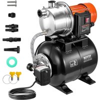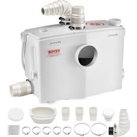
FLO1200 - Water pump Vevor - Free user manual and instructions
Find the device manual for free FLO1200 Vevor in PDF.


User questions about FLO1200 Vevor
0 question about this device. Answer the ones you know or ask your own.
Ask a new question about this device
Download the instructions for your Water pump in PDF format for free! Find your manual FLO1200 - Vevor and take your electronic device back in hand. On this page are published all the documents necessary for the use of your device. FLO1200 by Vevor.
USER MANUAL FLO1200 Vevor
Technical Support and E-Warranty Certificate www.vevor.com/support
MACERATOR PUMP
USER MANUAL
MODEL: FLO1200
We continue to be committed to provide you tools with competitive price. "Save Half", "Half Price" or any other similar expressions used by us only represents an estimate of savings you might benefit from buying certain tools with us compared to the major top brands and does not necessarily mean to cover all categories of tools offered by us. You are kindly reminded to verify carefully when you are placing an order with us if you are actually saving half in comparison with the top major brands.
VEVOR®
TOUGH TOOLS, HALF PRICE
MACERATOR PUMP
MODEL:FLO1200
NEED HELP? CONTACT US!
Have product questions? Need technical support? Please feel free to contact us:
Technical Support and E-Warranty Certificate
www.vevor.com/support
This is the original instruction, please read all manual instructions carefully before operating. VEVOR reserves a clear interpretation of our user manual. The appearance of the product shall be subject to the product you received. Please forgive us that we won't inform you again if there are any technology or software updates on our product.
Kindly Reminder

The FL01200 has been developed with the utmost care, and it is tested in the factory. Therefore, it is possible that the test water remains in the appliance.
GENERAL DESCRIPTION
The equipment should be avoided for commercial use; the FL01200 is exclusively reserved for indoor use. The macerator pump system of the appliance is integrated in a special way, which is only suitable for toilets with a horizontal outlet(P-trap toilet). The macerating pump starts automatically when a certain water level is reached. For the proper operation of the grinder, it is necessary important to follow the installation and maintenance instructions in this manual.
When properly installed and maintained according to the instructions in this user manual, the appliance is very powerful, safe, and reliable.
1. General description
The FLO1200 pump is exclusively reserved for indoor use. The macerator pump system of the appliance is integrated in a special way, which is only suitable for toilets with a horizontal outlet. For the proper operation of the grinder it is necessarily important to follow the installation and maintenance instructions in this manual.
When properly installed and maintained according to the instructions in this user manual, the appliance is very powerful, safe and reliable.
Users for commercial or industrial purposes should be avoided. The appliance goes to working status in every 10 seconds. The macerator pump starts automatically when a certain water level is reached.
FLO1200 is specially to connect with:
·WC
- Shower
- Wash basin
- Washing machine
- Bidet
·Kitchen
Urinal
2. Technical Data
| Model Input | Max Power | Max Flow | Max Lift | Water Inlet | Water Outlet | |
| FLO1200 (US) | AC110-120V 60Hz | 1.6 HP | 48GPM 33ft | WC+3 | 1 | |
| FLO1200 (EU) | AC220-240V 50Hz | 1200 W | 180 LPM | 10m | WC+3 | 1 |
WARNING: Only installations conforming to the above specifications are acceptable.
3-1. Parts List
| A-B x1 | Ex1 | Fx3 | Gx1 |
| Hx3 | The accessory"H"is mounted on the pump | Lx1 40-60MM | Mx4 32-50MM |
| Nx1 90-110MM | P x1 100-12MM | Qx1 | Rx1 |
3-1. Parts List
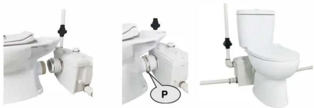
Install the rubber ring (Q) that connects the toilet to the front end of the sewage pump, and fix it with a clamp (N) (90-110mm) to connect the toilet. See the figure below for reference.
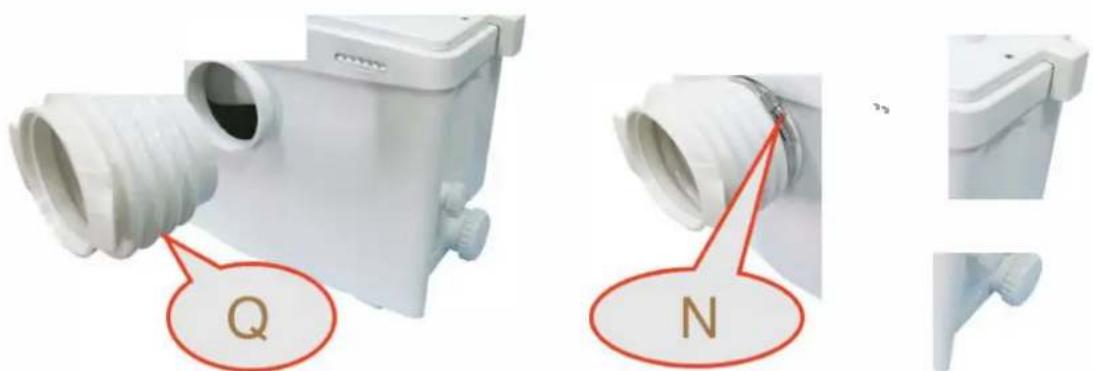
3-3. Connecting the Shower and Washbasin
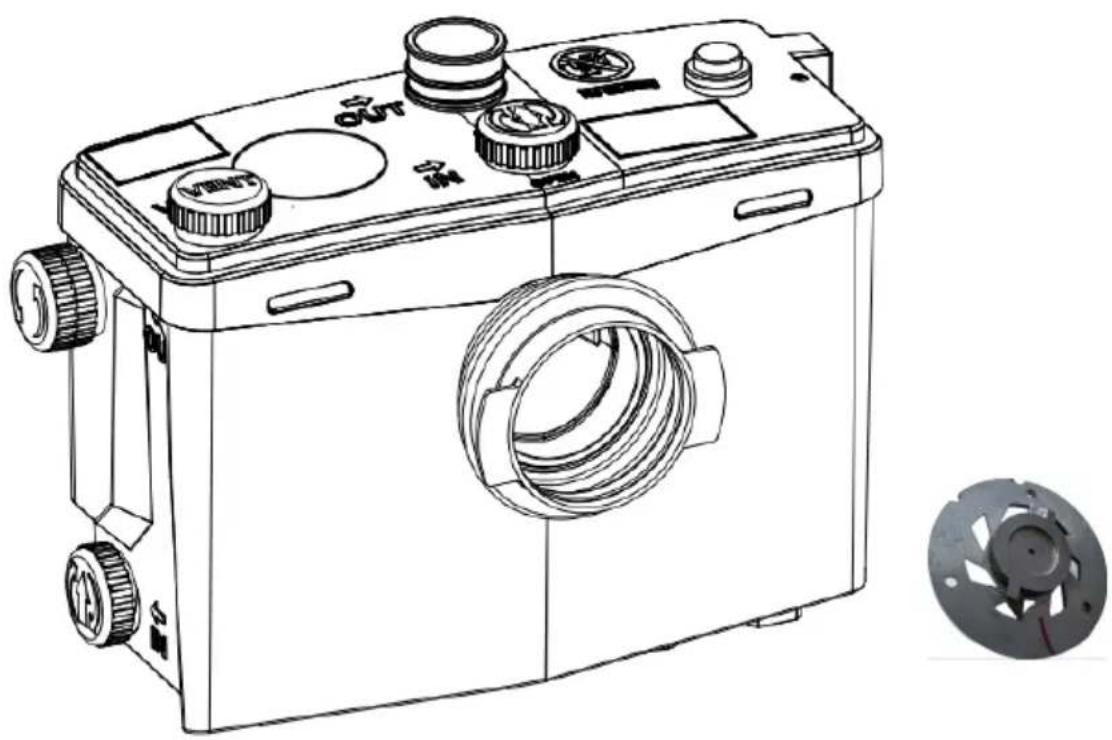
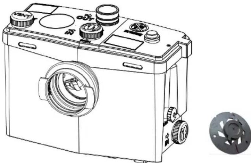
The drain pipes of the shower and washbasin are connected to the water inlets at both ends of the bottom of the pump. First, remove the plugs from the water inlets on both sides of the bottom of the pump (turn the arrow on the plug downwards to pull it out forcefully), and you can see the built-in check valve m the pump that prevents sewage backflow. Then install the inlet hose (F) and fix it with a clamp (M) (32-50mm).
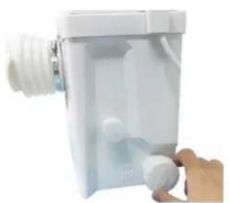
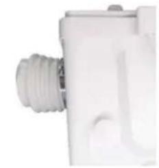
check valve
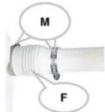
The pipe size for connecting the shower or washbasin wastewater to the pump is 40mm . If connecting the shower, the bottom of the shower needs to be raised by 20cm , and the drain pipe must maintain a 3% slope to let the wastewater flow into the pump by gravity, preventing the wastewater from staying in the inlet pipe and producing an odor.
If not connecting a toilet, use accessory (G) to plug the water inlet at the front of the pump. Refer to the following installation diagram:
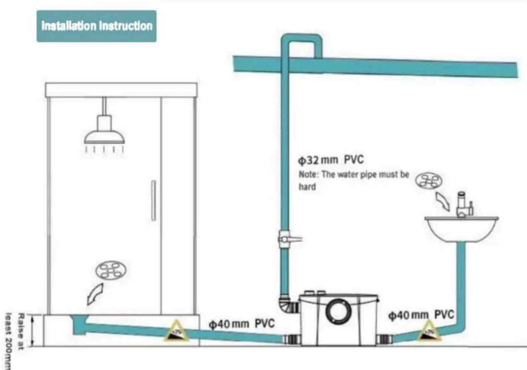
The drain pipe is always connected to the main sewage pipe. The connection method is shown in the following figure:
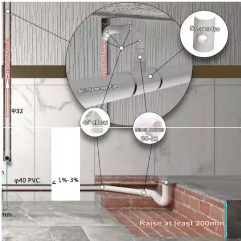
3-4. Connecting the Drain Pipe
There are two connection schemes for the drain pipe.
Scheme one: The drain pipe is connected to the top of pump
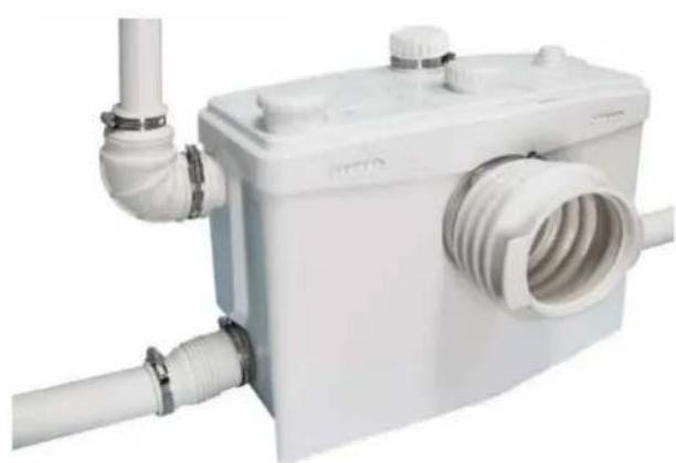
The side outlet of the pump is already plugged at the factory. If you need to use the top outlet, do not remove the side outlet. Connect the elbow with the check valve (A-B) to the drain outlet on the top of the pump. The drain elbow can be connected to a pipe with a diameter of 28mm , 32mm , or 40mm . Do not use a pipe with a diameter exceeding 40mm , as it will affect the height of the drainage.
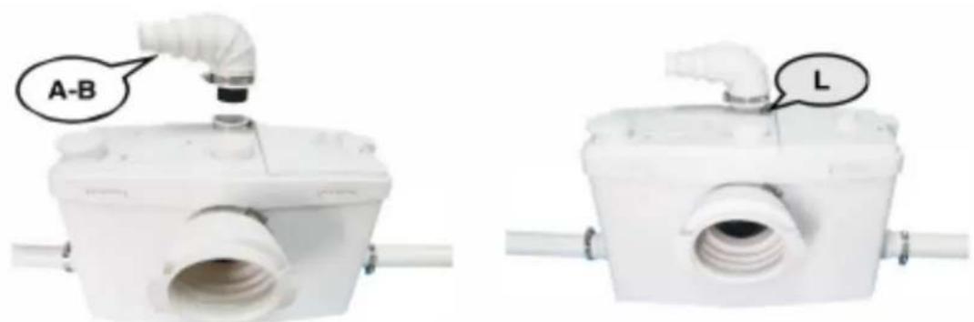
Refer to the following installation diagram:
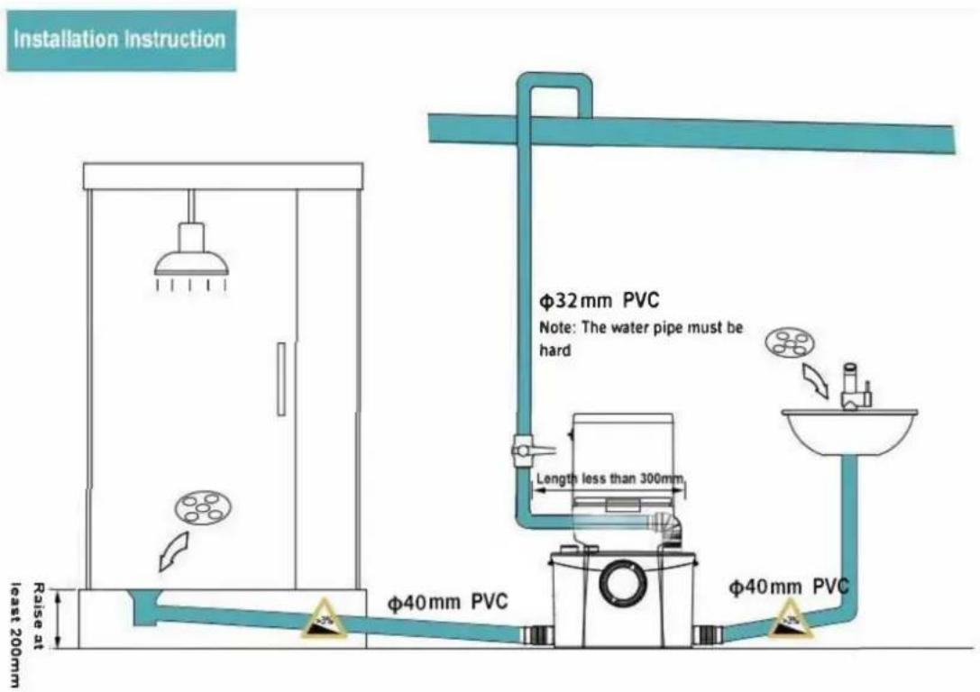
Scheme tow: The drain pipe is connected to the side of pump.
First, plug the water outlet at the top of the pump with a plug (E), and remove the plug on the side of the pump.
Remove the black check valve from accessory A-B, install it on the side outlet, and tighten it with a clamp (L).
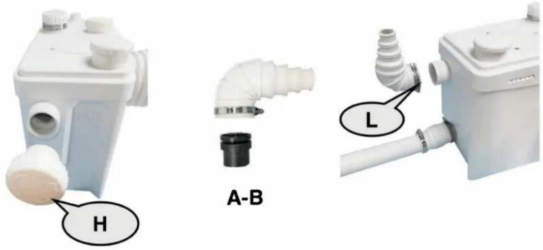
Use a utility knife to cut off the excess size at the elbow joint.
Note: Do not install check valve C in reverse, otherwise, the sewage cannot be discharged. The drain pipe inserted into the check valve must be fixed with waterproof glue to prevent leakage, and the other end is the same.
Note: To achieve the best performance of the pump, first drain upwards, then horizontally. When draining horizontally, the drain pipe should have a downward slope of 10-15 degrees. Do not use right-angle (90 degrees) elbows, as they will affect the vertical lifting effect.
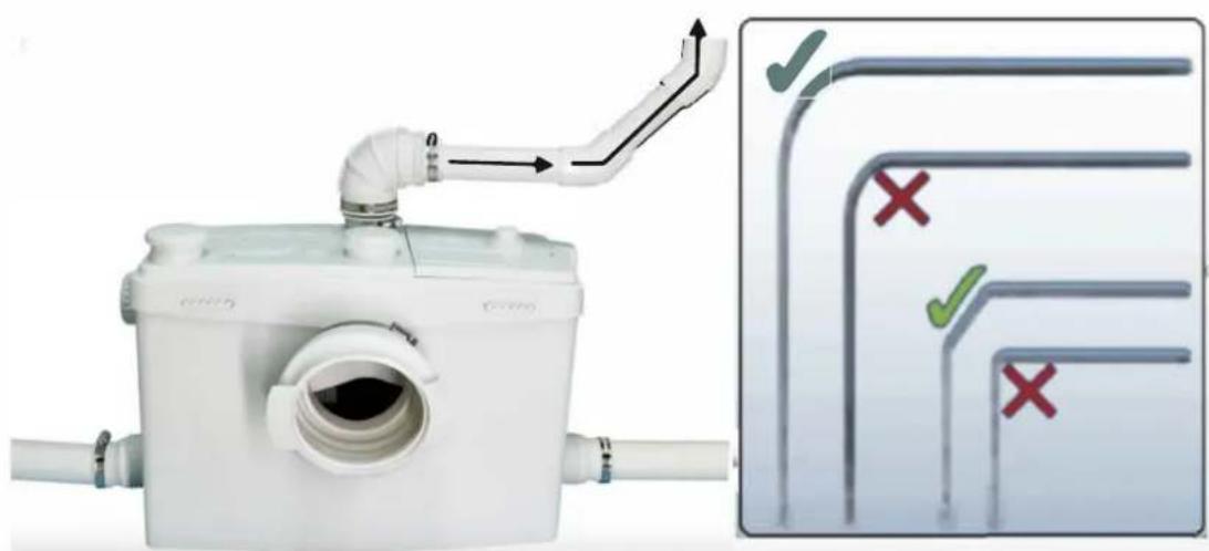
The schematic diagram of the drain pipe installed on the side is:
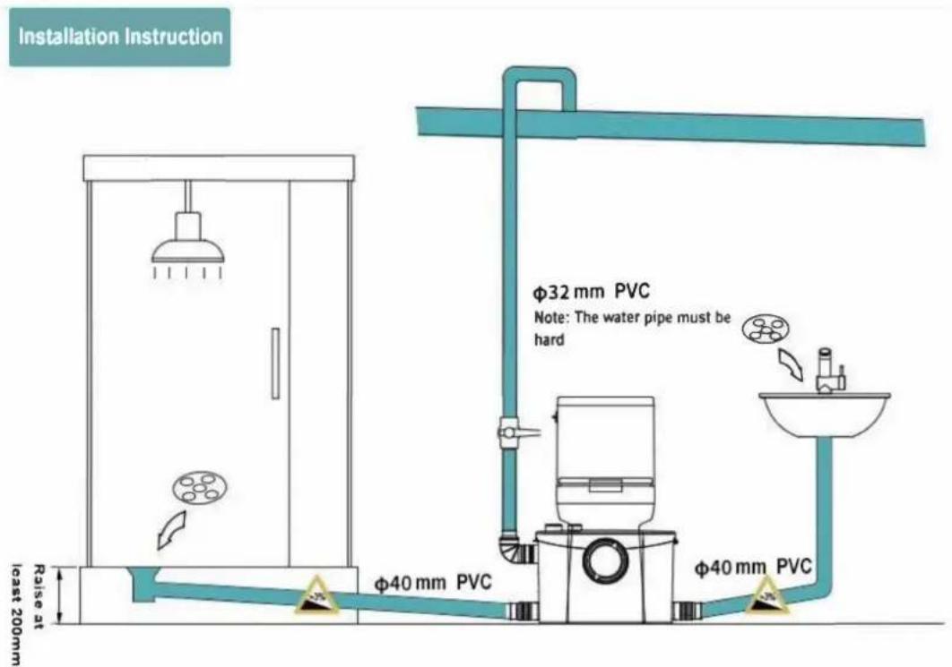
4. Connecting the Toilet
Place the toilet on the same level as the pump, align the rubber ring Q that has been installed on the pump with the drain outlet of the toilet, and push it in forcefully. Then fix it with a clamp (P) (100-120mm).
5. Activated Carbon Deodorizing Device
There are two deodorization schemes for sewage pumps.
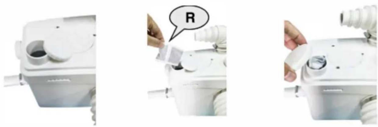
Scheme one: Open the lid of the activated carbon port, put the activated carbon bag (R) in, and then close the lid. The activated carbon should be replaced once a year.
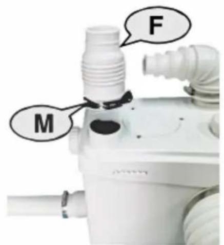
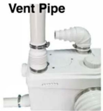
Scheme two: Open the lid, put the cut hose (F) over the activated carbon port, and fix it with a clamp (M) (32-50mm). The other end is connected to the exhaust pipe, the size of which is 40mm.
6. Connection to electrical supply
All wiring should be in accordance with the applicable electrical code in your territory. The macerating system requires a single-phase 1 10-120V or 220-240Vsupply. When installed in a bathroom, the receptacle should be 40 inches (IM) away (in a straight line) from a shower or bathtub. Connect only to receptacle protected by aground fault circuit interrupter(GFCI).
Warning: risk of electric shock - this pump is supplied with a grounding conductor and grounding type attachment plug to reduce the risk of electrical shock. Be certain that it is connected only to a properly grounded - type receptacle.
7.Usage
7-1 Macerating pump unit.
The normal domain of application of macerating units only concerns the disposal of human waste, toilet paper and water.
FL01200 is designed for family use only and cannot accept without damage the disposal of sanitary items such as condoms, tampons, sanitary pads and cotton swabs.
7-2 CAUTIONARY NOTES:
Do not discharge any acids, alkaloids, solvents painting, paint strippers, food waste, plastic bags, metal such as nails, hairpins, wood, building materials, kitty litter or anything that could halt or damage or corrode the unit. Disregarding the above might damage the macerating unit and shall void your warranty.
Do not hang bleach blocks or hydrochloride cleaners in the toilet tank. These solutions have been shown to deteriorate the plastic and neoprene components of the flush and fill valves, and may cause leaks. In the event of a power loss do not use the toilet or any other sanitary fixture connected to the macerating unit since it will not work until the power is restored.
The toilet works as a conventional flushing toilet and needs no maintenance in normal use. However, there is nothing wrong with cleaning out the macerating unit once a year. Do not use bleach (Be careful not to let water enter the electrical cord opening). The macerating unit starts automatically once the toilet is flushed or the bath, shower, hand basin, etc. discharge and cease operation once the contents have been pumped away.
Whenever the unit is not to be used for long periods of time (vacation, power failure, maintenance, etc.) turn off the water supply to the tank and flush the unit to evacuate the water. No leakage into the bowl should ever be permitted from the tank.
In areas, which are prone to freezing, the total system must be properly winterized. This includes the draining of all pipes, the toilet tank and bowl and the macerating tank. The macerating system is simple to winterize. Pour a jug of plumbers anti-freeze into the tank and flush the toilet. This will cause the macerating unit to activate and a11 remaining water will be replaced by plumber's anti-freeze. No parts or labour are warranted when a breakdown occurs due to freezing.
Ensure that there are no faucets left open. Drops will eventua11y fi] up the pump and the resultant repeated start-stop of the motor may heat up to such an extent, that the thermal overload switch may eventually operate and automatically stop the motor, thus possibly causing a flood.
8. DISASSEMBLY FOR LITTLE INTERVENTION
As the unit is connected to the water and electrical supply, it is important to check that the following actions have been taken before removing the unit:
(1). If possible, close off the water supply to the tank and close the ball or gate valve on the outlet pipe.
(2). Pull the electrical cord out of the receptacle before removing unit.
(3). Empty out as much water as possible from the toilet tank and the toilet bowl.
(4). Disconnect toilet from unit. Remove toilet bowl and set aside against a wall to prevent from tipping over.
(5). The use of a dry/wet type vacuum cleaner might assist you greatly in removing the residual water in the bowl or macerating unit.
(6). When you have to remove the macerating unit, carefully disconnect the inlet drainpipes, (there might be residual water inside).
(7). Side inlet valves clogged: remove the sleeves and use a screwdriver to free or clean the rubber flap if necessary.
(8). CAUTIONARY NOTE
Do not immerse unit totally in water. Do not let water enter the electrical cord entrance opening.
(9). REASSEMBLY OF THE LID
When replacing the lid grease the rubber gasket lightly with soapy water or dishwasher liquid. (Do not use Vaseline as this may expand the neoprene materials). The gasket must be inside the lid first. Start by pushing the lid down at the cord side first, then work your way around and tap on the lid with a rubber mallet or bloc.
NOTICE
If the product has a delay function. When the switch is turnedoff, the motor will be delayed for 4 seconds to stop working.

FCC Information:
CAUTION: Changes or modifications not expressly approved by the party responsible for compliance could void the user's authority to operate the equipment!
This device complies with Part 15 of the FCC Rules. Operation is subject to the following two conditions:
1) This product may cause harmful interference.
2)This product must accept any interference received, including interference that may cause undesired operation.
WARNING: Changes or modifications to this product not expressly approved by the party.responsible for compliance could void the user's authority to operate the product.
Note: This product has been tested and found to comply with the limits for a Class B digital device pursuant to Part 15 of the FCC Rules, These limits are designed to provide reasonable protection against harmful interference in a residential installation.
This product generates, uses and can radiate radio frequency energy, and if not installed and used in accordance with the instructions, may cause harmful interference to radio communications. However, there is no guarantee that interference will not occur in a particular installation. If this product does cause harmful interference to radio or television reception, which can be determined by turning the product off and on, the user is encouraged to try to correct the interference by one or more of the following measures.
Reorient or relocate the receiving antenna.
- Increase the distance between the product and receiver.
- Connect the product to an outlet on a circuit different from that to which the receiver is connected.
- Consult the dealer or an experienced radio/TV technician for assistance.

Correct Disposal
This product is subject to the provision of european Directive 2012/19/EU. The symbol showing a wheelie bin crossed through indicates that the product requires separate refuse collection in the European Union. This applies to the product and all accessories marked with this symbol. Products marked as such may not be discarded with normal domestic waste, but must be taken to a collection point for recycling electrical and electronic devices.
VEVOR®
TOUGH TOOLS, HALF PRICE
TechnicalSupportandE-WarrantyCertificate
www.vevor.com/support
VEVOR®
TOUGH TOOLS, HALF PRICE
Assistance technique et certificat de garantie electronique www.vevor.com/support
POMPE MACERATEUR
MANUEL D'UTILISATION
MODELE:FL01200
www.vevor.com/support
www.vevor.com/support
www.vevor.com/support
VEVOR®
TOUGH TOOLS, HALF PRICE
www.vevor.com/support
elettronica www.vevor.com/support
VEVOR®
TOUGH TOOLS, HALF PRICE
Soporte专业技术o y certificate de garantia electrònica www.vevor.com/support
BOMBA MACERADORA
MANUAL DEL USUARIO
MODELO:FL01200
Seguimos comprometidos a brindar herramentas a precios competitos.
www.vevor.com/support
www.vevor.com/support
HULP NODIG? NEEM CONTACT MET ONS OP!
www.vevor.com/support
7-2 WAARSCHUWINGEN:Laat
www.vevor.com/support
deodorisingsscheman for avloppspumper.
7-1 Macerationspumpenhet.
www.vevor.com/support