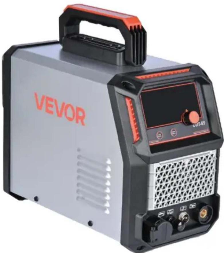
USER MANUAL CUT-65 Vevor
Affordable. Reliable. Home Improvement.
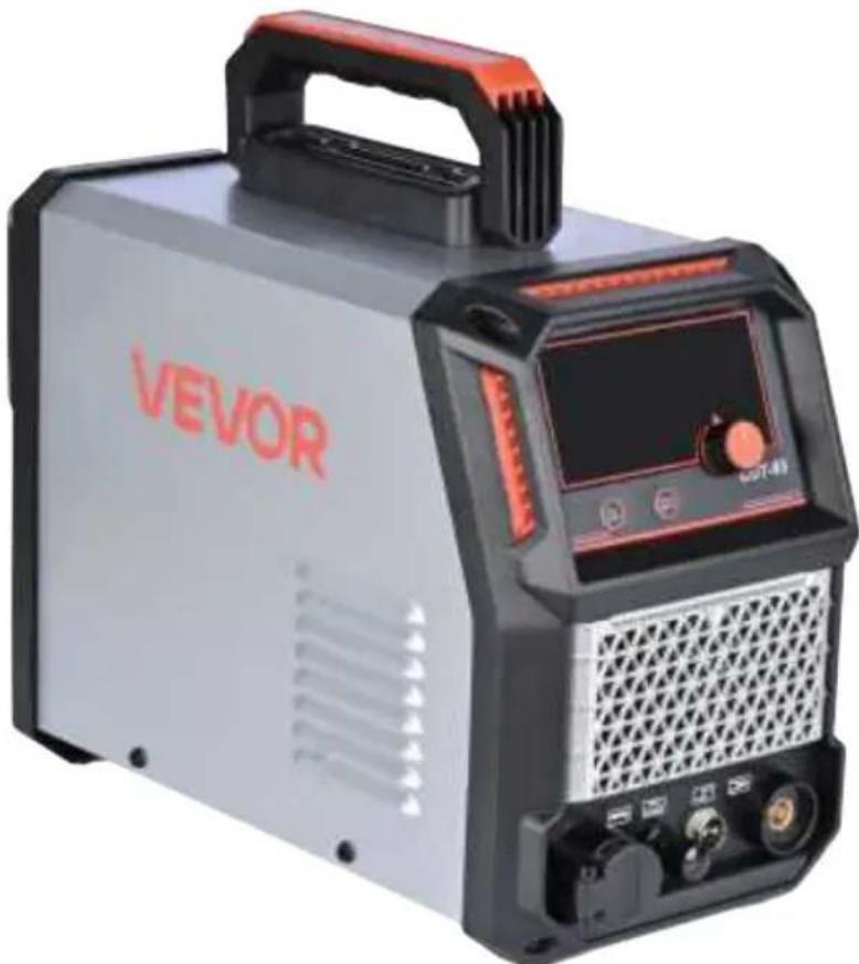
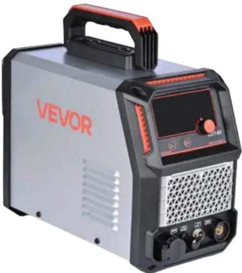
PLASMACUTTERMACHINE
MODEL:CUT-65
VEVOR
Affordable. Reliable. Home Improvement.
PLASMACUTTERMACHINE
Model:CUT-65
natural_image
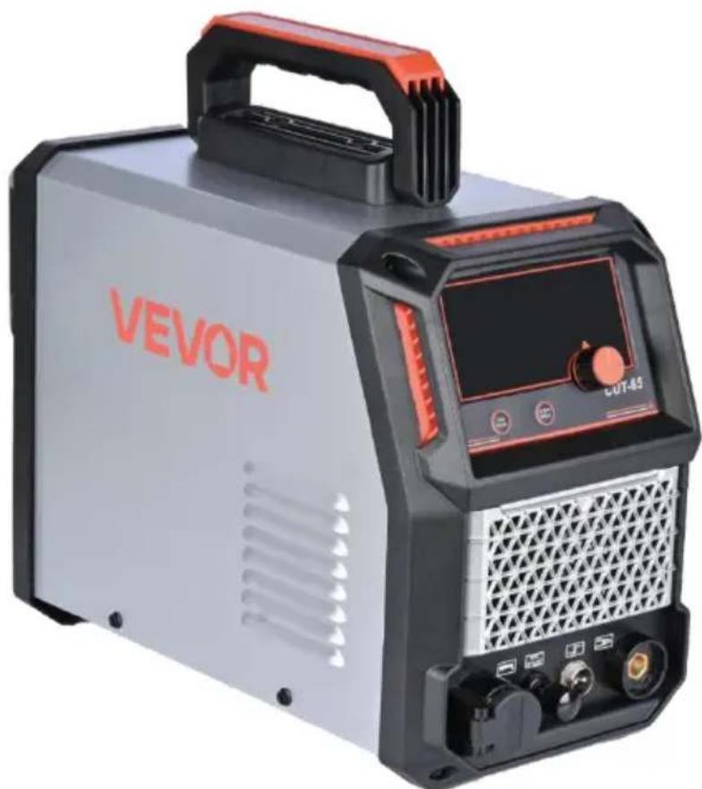
Exterior view of a Vevor industrial testing device with control panel and buttons (no readable text beyond branding)
Note: The product picture is for reference,the actual details shall prevail
This is the original instruction, please read all manual instructions carefully before operating. VEVOR reserves a clear interpretation of our user manual. The appearance of the product shall be subject to the product you received. Please forgive us that we won't inform you again if there are any technology or software updates on our product.
 | Warning-To reduce the risk of injury, user must read instructions manual carefully. |
 | This product is subject to the provision of european Directive 2012/19/EU. The symbol showing a wheelie bin crossed through indicates that the product requires separate refuse collection in the European Union. This applies to the product and all accessories marked with this symbol. Products marked as such may not be discarded with normal domestic waste, but must be taken to acollection point for recycling electrical and electronic devices. |
 | Compliance is a EC security certification. |
The CUT-65 provides a powerful and efficient method for air plasma cutting of carbon steel, stainless steel, and other conductive metals. Utilizing advanced inverter technology, it delivers precise, clean cuts on both thin and thick materials with minimal slag. When equipped with the optional air compressor (not included) and proper air filtration, the CUT-65 ensures smooth, high-speed cutting performance for industrial and workshop applications.
SPECIFICATIONS
| OutputCurrent Range: | Input Current | Input Voltage | RatedDuty Cycle | MaximumCutting Thickness | Air pressure |
| CUT 65A | 220V I1 max 32A220V I1 eff 24.8A | 220V-1 | CUT 20%@65A | 20mm | 1-99PS1 |
DUTY CYCLE
The rated duty cycle refers to the amount of welding that can be done within an amount of time. The CUT-65 has a duty cycle of 60% at 65A. It is easiest to look at your welding time in blocks of 10 minutes and the duty cycle being a percentage of that 10 minutes. If welding at 65A with a 60% duty cycle, within a 10 minute block of time you can weld for 6 minutes with 4 minutes of cooling for the welder. If the duty cycle is exceeded, the welder will automatically shut off, however the fan will continue running to cool the overheated components. When a safe temperature has been reached, the welder will automatically switch the welder output back on. To increase the duty cycle you can turn down the amperage output control.
READ AND UNDERSTAND ALL INSTRUCTIONS AND PRECAUTIONS BEFORE PROCEEDING.
This unit emits a powerful high voltage and extreme heat which can cause severe burns, dismemberment, electrical shock and death. VEVOR shall not be held liable for consequences due to deliberate or unintentional misuse of this product.
The following explanations are displayed in this manual, on the labeling, and on all other information provided with this product:
DANGER
DANGER indicates a hazardous situation which, if not avoided, will result in death or serious injury.
WARNING
WARNING indicates a hazardous situation which, if not avoided, could result in death or serious injury.
CAUTION
CAUTION used with the safety alert symbol, indicates a hazardous situation which, if not avoided, could result in minor or moderate injury.
A NOTICE
NOTICE is used to address practices not related to personal injury.
▲ READ INSTRUCTIONS
Thoroughly read and understand this manual before using the welder. Save for future reference.

▲ DANGER ELECTRIC SHOCK CAN KILL!
- Improper use of an electric welder can cause electric shock, injury and death! Read all precautions described in the Welder Manual to reduce the possibility of electric shock.
- Disconnect welder from power supply before assembly, disassembly or maintenance of the torch, contact tip and when installing or removing nozzles.
• Always wear dry, protective clothing and leather welding gloves and insulated footwear. Use suitable clothing made from durableflame-resistant material to protect your skin.
- If other persons or pets are in the area of welding, use welding screens to protect bystanders from sparks.
• Always operate the welder in a clean, dry, well ventilated area. Do not operate the welder in humid, wet, rainy or poorly ventilated areas.
- The electrode and work (or ground) circuits are electrically "hot" when the welder is on. Do not allow these "hot" parts to come in contact with your bare skin or wet clothing.
- Separate yourself from the welding circuit by using insulating mats to prevent contact from the work surface.
- Be sure that the work piece is properly supported and grounded prior to beginning an electric welding operation.
• Always attach the ground clamp to the piece to be welded and as close to the weld area as possible. This will give the least resistance and best weld.
▲ DANGER WELDING SPARKS CAN CAUSE FIRE OR EXPLOSION!
- Electric welding produces sparks which can be discharged considerable distances at high velocity igniting flammable or exploding vapors and materials.
- Do not operate electric arc welder in areas where flammable or explosive vapors are present.
- Do not use near combustible surfaces. Remove all flammable items within 35 feet of the welding area.
• Always keep a fire extinguisher nearby while welding.
- Use welding blankets to protect painted and or flammable surfaces; rubber weather-stripping, dash boards, engines, etc.
- Ensure power supply has properly rated wiring to handle power usage.
WARNING ELECTROMAGNETIC FIELDS CAN BE A HEALTH HAZARD!
- The electromagnetic field that is generated during arc welding may interfere with various electrical and electronic devices such as cardiac pacemakers. Anyone using such devices should consult with their physician prior to performing any electric welding operations.
- Exposure to electromagnetic fields while welding may have other health effects which are not known.
WARNING ARC RAYS CAN BURN!
- Arc rays produce intense ultraviolet radiation which can burn exposed skin and cause eye damage. Use a shield with the proper filter (a minimum of #11) to protect your eyes from sparks and the rays of the arc when welding or when observing open arc welding (see ANSI Z49.1 and Z87.1 for safety standards).
- Use suitable clothing made from durable flame-resistant material to protect your skin.
- If other persons or pets are in the area of welding, use welding screens to protect bystanders from sparks and arc rays.

▲ WARNING FUMES AND WELDING GASES CAN BE A HEALTH HAZARD!
- Fumes and gasses released during welding are hazardous. Do not breathe fumes that are produced by the welding operation. Wear an OSHA-approved respirator when welding.
• Always work in a properly ventilated area.
- Never weld coated materials including but not limited to: cadmium plated, galvanized, lead based paints.
• Electric welding heats metal and tools to temperatures that will cause severe burns!
- Use protective, heat resistant gloves and clothing when using Eastwood or any other welding equipment. Never touch welded work surface, torch tip or nozzle until they have completely cooled.

- Grinding and sanding will eject metal chips, dust, debris and sparks at high velocity. To prevent eye injury wear approved safety glasses.
- Wear an OSHA-approved respirator when grinding or sanding.
- Read all manuals included with specific grinders, sanders or other power tools used before and after the welding process. Be aware of all power tool safety warnings.
REQUIRED ITEMS
Before you begin using the CUT-65, make sure you have the following:
• A properly grounded 1Phase 220V 65A circuit breaker.
NOTE: Unit must be grounded to work properly and safely!
- A clean, safe, well-lit, dry and well-ventilated work area.
• A non-flammable, long sleeve shirt or WELDING Jacket
• Heavy Duty Welding Gloves
- Auto-Darkening Welding Helmet to provide eye protection during welding operations. Note: MUST be a #11 lens or darker.
• Dedicated stainless steel wire welding brushes for each material to be welded.
CONTENTS
Remove all items from the box. Compare with list below to make sure unit is complete.
1.CUT-65
2.2m 16mm ^4 Ground clamp 300A 1 set ×1
3. Air pressure regulator ×1
4. Plasma cutting torch AG-60 ×1
5. Transparent air hose 2m ×1
6.PTFE tape (plumber's tape) ×1
7. Hose clamps ×4
natural_image
Exterior view of a Vevor industrial testing device (no visible text or symbols on the device body)
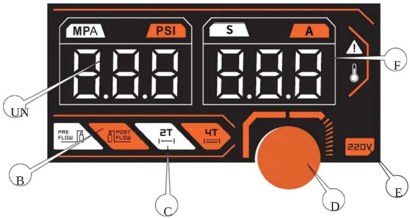
CONTROL AND DISPLAY PANEL
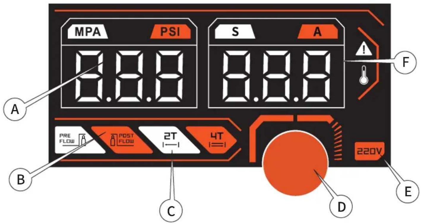
A: Air Pressure Display B: Pre-flow / Post-flow
C: 2 T / 4 T
D: Encoder Knob
E: Input Voltage Display F: Current (A) Display
Click the button to select the function to be steady on In-screen alarm such as thermal protection
| Welding Mode | Current(A) |
| 220V-1 |
| 20-65CUT |
Thermal protection LED illuminates when the unit has reached the maximum internal component temperature. This occurs when the duty cycle has been exceeded.
The Welder will automatically shut off however the fan will continue running to cool the overheated components. When a safe temperature has been reached, the protective circuit will automatically switch the welder output back on.
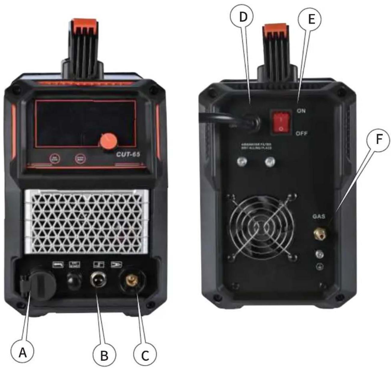
A: Plasma Torch Port
B: Torch Trigger Socket
C: Ground Clamp Terminal D: Power Input Cable
E: Power Switch F: Gas Inlet
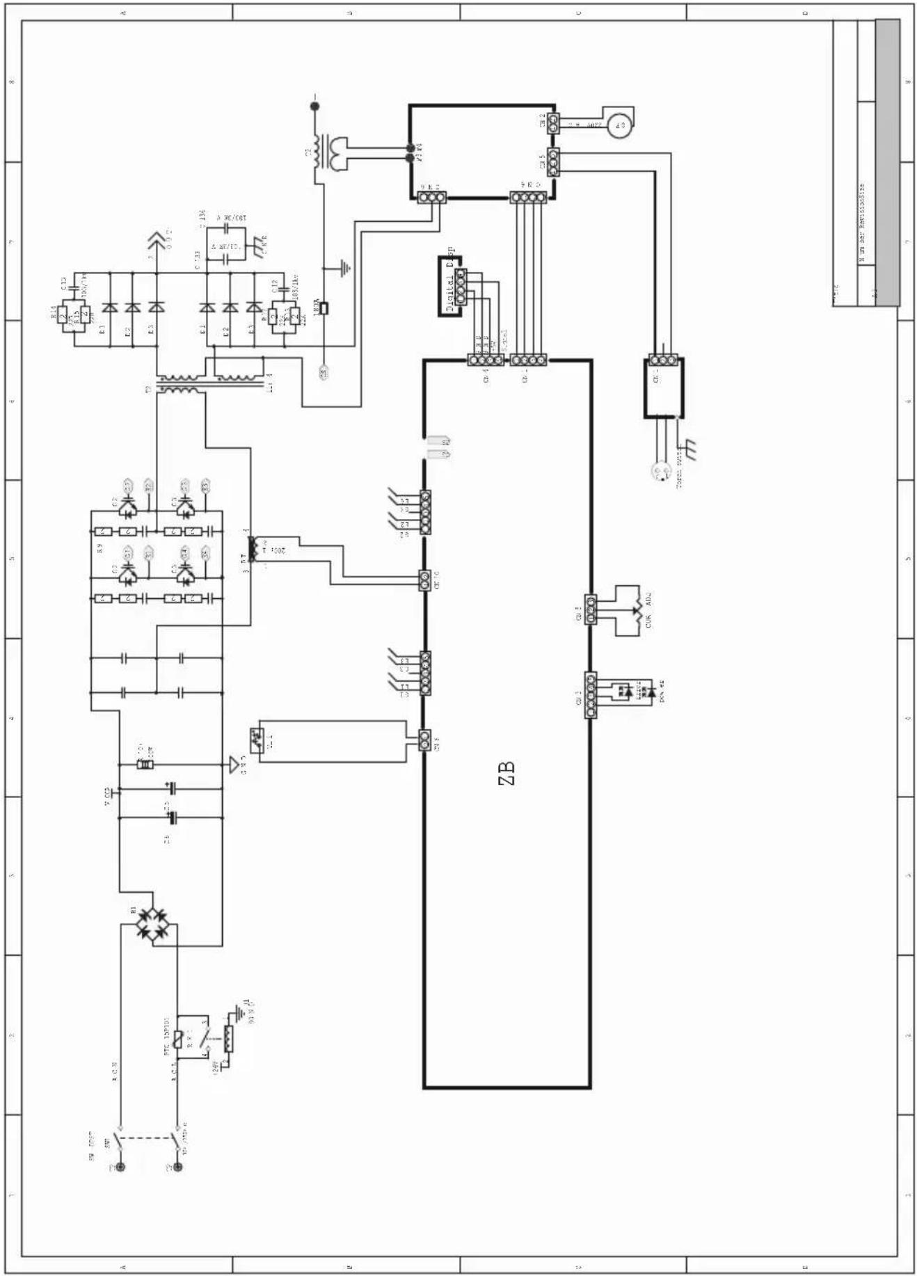
CUT CONNECTION DIAGRAM
natural_image
Electrical testing setup with a digital multimeter, coiled cable, and clamp on a dark surface (no visible text or symbols)
-
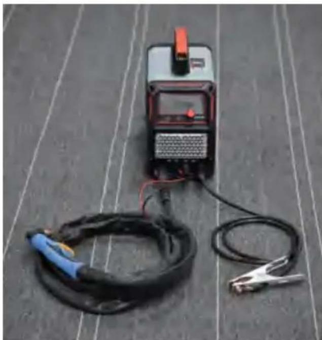
Insert the quick-connect grounding cable into the CUT terminal output on the machine and attach the ground clamp to the workpiece.
-
Connect the torch to the machine's torch socket, then plug the torch switch control cable into the machine's 2-pin socket.
-
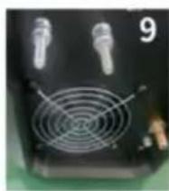
Connect the rear panel air inlet to the compressed air supply.
-
Power on the machine and press the torch switch to enter normal cutting operation.
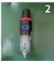
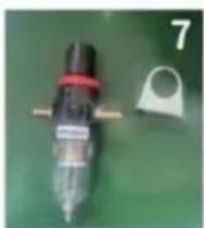
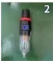
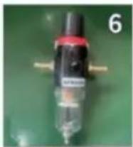
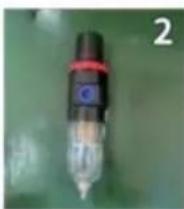
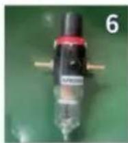
Air Pressure Regulator Connection Diagram. The proper cutting air pressure range is 95-99PSI.
INSTALLATION STEPS FOR AIR PRESSURE REGULATOR VALVE:
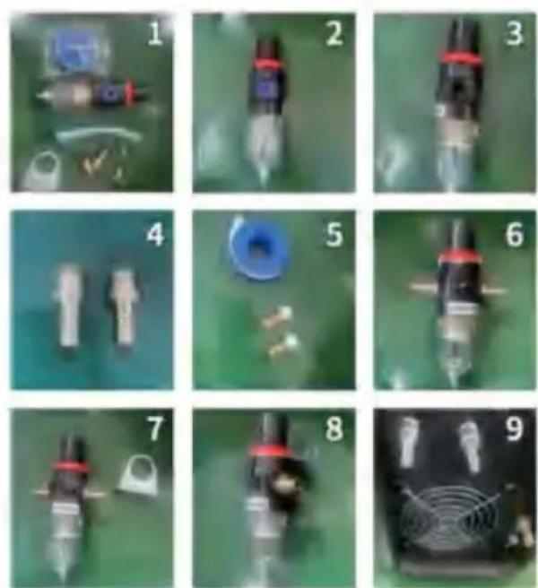
- Gather all pressure regulator valve accessories from inside the machine.
- Locate the air pressure regulator valve.
- Remove the plug from the outlet of the pressure regulator valve.
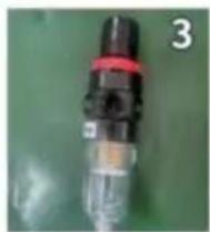
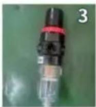
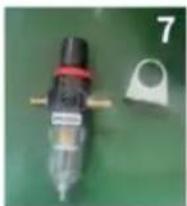
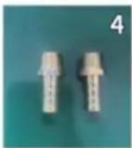
4.Find the air connector.
- Wrap the air connector with PTFE tape (thread seal tape).
- Screw the air connector into the inlet and outlet ports of the pressure regulator valve.
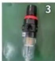
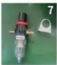
- Locate the mounting bracket for the pressure regulator valve.
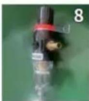
-
Attach the bracket to the pressure regulator valve.
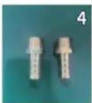
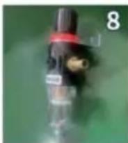
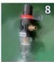
-
Find the fixing bolts on the rear panel of the machine.
-
Remove the two self-locking nuts from the bolts.
-
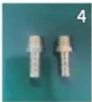
Wrap both the air connector (Pic 11) and the air connector on the machine's rear panel (Pic 12) with PTFE tape.
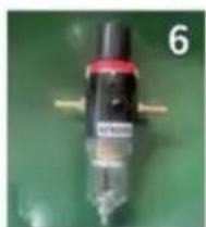
-
Install the pressure regulator valve onto the rear panel of the machine and tighten it with nuts.
-
Pay attention to the inlet and outlet directions of the pressure regulator valve.
-
Connect the air hose to the outlet of the pressure regulator valve and secure it with a hose clamp.
-
Attach the other end of the air hose to the air inlet on the rear panel of the machine and secure it with a hose clamp.
-
Pull up and rotate the top cover of the pressure regulator valve to adjust the air pressure.
PREPARING TO "STICK" WELDING
- Plug the power cord into a properly grounded, 1Phase 220V,65A circuit breaker.
- Make sure the electrode or "Stick" is not making contact with the grounded workpiece.
- Switch the Power Switch to "ON".
DANGER
ELECTRIC SHOCK CAN CAUSE INJURY OR DEATH!
The electrode and work (or ground) circuits are electrically "hot" when the welder is on. Do not allow these "hot" parts to come in contact with your bare skin or wet clothing. Always wear dry, protective clothing and leather welding gloves and insulated footwear.
WARNING
ARC RAYS CAN BURN!
Arc rays produce intense ultraviolet radiation which can burn exposed skin and cause eye damage. Use a shield with the proper filter (a minimum of #11) to protect your eyes from sparks and the rays of the arc when welding or when observing open arc welding (see ANSI Z49.1 and Z87.1 for safety standards).
DANGER
WELDING SPARKS CAN CAUSE FIRE OR EXPLOSION!
Electric welding produces sparks which can be discharged considerable distances at high velocity igniting flammable or exploding vapors and materials. Remove all flammable items within 35 feet of the welding area. Always keep a fire extinguisher nearby while welding.
WARNING
FUMES AND WELDING GASES CAN BE A HEALTH HAZARD!
Fumes and gasses released during welding are hazardous. Do not breathe fumes that are produced by the welding operation. Wear an OSHAapproved respirator when welding. Always work in a properly ventilated area.
CAUTION
HOT METAL AND TOOLS WILL BURN!
Electric welding heats metal and tools to temperatures that will cause severe burns! Use protective, heat resistant gloves and clothing.
- While wearing a properly functioning Auto Darkening Welding Helmet, lightlydrag the tip of the Welding Rod along the workpiece surface to start an arc.
- Feed the Welding Rod into the workpiece joint at a 15° angle.
- Lift rod from workpiece when weld bead is completed.
- Turn off Welder power switch.
- Set the Electrode or "Stick" Holder on a safe, non-flammable, surface.
TROUBLESHOOTING
| PROBLEM | CAUSE | CORRECTION |
| Contamination in weld bead | Contaminated Electrode Rod | Make sure that Electrodes are clean and dry before use. |
| Contaminated Base Metal | Clean base metal of any oil, debris, coatings, or moisture. If base metal is cold rolled steel make sure to remove any mill scale. |
| Poor Weld Appearance | Incorrect positioning | The angle of the electrode should be at 45° and drug away from the weld arc. Failing to do so may cause poor weld appearance. |
| Weld Bead is Cracking | Too much heat in material | Reduce heat & allow more time between passes. |
| Base Metal is absorbing too much heat | Preheat base metal (consult welding codes for requirements) |
| Incorrect Filler Wire | Use correct filler wire type & diameter for the joint being welded. |
| Material is Warping | Insufficient Clamping | Clamp work piece tightly & weld while cIA are in place. |
| Insufficient Tack Welds | Add more tack welds until rigidity and stiffness is developed. |
| Too Much Heat in Material | To reduce heat it is best to spread the welding out around the area. This can be done by using stitch welding techniques, alternating sides, and/or taking your time and allowing the pieces to cool between passes. |
| Porosity in weld bead | Contaminated Electrode Rod | Make sure that Electrodes are clean and dry before use. |
| Contaminated base metal | Clean base metal making sure to remove any oil, debris, coatings, or moisture. |
| Difficulty Starting Arc | Incomplete Circuit | Check Ground connection. Make sure that the ground is on a freshly cleaned surface and close to the welding area. It is suggested to weld toward the ground connection |
| Amperage Too Low | Based on the material welding & size/material of the electrode, pick an appropriate amperage to perform the desired weld. |
| Contaminated Base Metal | Clean base metal of any oil, debris, coatings, or moisture. If base metal is cold rolled steel make sure to remove any mill scale. |
| Arc Wander | Electrode too far from welding surface | Move electrode so that it is contacting the weld puddle and feed rod into the puddle as needed. |
| Difficulty Holding Arc | Amperage Too Low | Based on the material welding and size/material of the electrode, pick an appropriate amperage to perform the desired weld. |
| Electrode too far from welding surface | Move electrode so that it is contacting the weld puddle and feed rod into the puddle as needed. |
| Incomplete Circuit | Check Ground connection. Make sure that the ground is on a freshly cleaned surface and close to the welding area. It is suggested to weld toward the ground connection. |
| Contaminated Electrode Rod | Make sure that Electrodes are clean and dry before use. |
| Contaminated Base Metal | Clean base metal of any oil, debris, coatings, or moisture. |
Manufacturer: Zhejiang Xingyi Ventilator Electrical Appliance Co., Ltd.
Address: Danya Industrial Park, Zeguo Town, WENLING Zhejiang 317523
Imported to AUS: SIHAO PTY LTD. 1 ROKEVA STREETEASTWOOD
NSW 2122 Australia
YH CONSULTING LIMITED. C/O YH Consulting Limited Office 147, Centurion House, London Road, Staines-upon-Thames, Surrey, TW18 4AX
Affordable. Reliable. Home Improvement.
DÉCOUPEUR PLASMA MACHINE
MODÈLE : COUPE -65
VEVOR
Affordable. Reliable. Home Improvement.
PLASMA CUTTER MACHIN
Modèle : CUT -65
natural_image
Exterior view of a VEVOR industrial testing device (no visible text or symbols on the device body)
WARNING ARC RAYONS PEUT BRÜLER!
natural_image
Exterior view of a VEVOR industrial testing machine (no visible text or symbols on the device body)
CONTRÔLE ET AFFICHER PANNEAU

natural_image
Exterior view of a welding torch and power supply unit on a carpet (no visible text or symbols)
| poor weld Appearance | Incorrect positioning | The angle of the electrode should be at 45, and drug away weld arc. Failing to do so may cause poor weld appearance. |
| weld Bead is cracking | Too much heat in materia | Reduce heat & allow more time between passes. |
| Base Metal is absorbing tc much heat | preheat base metal (consult welding codes for requirement) |
| Incorrect Filler wii | use correct filler wire type & diameter for the joint being we |
| Material is warping | Insufficient clamping | clamp work piece tightly & weld while cIA are in place. |
| Insufficient Tack weld | Add more tack welds until rigidity and stiffness is developed. |
| Too Much Heat in Mater | To reduce heat it is best to spread the welding out around the This can be done by using stitch welding techniques, alternatir sides, and/or taking your time and allowing the pieces to cool between passes. |
| porosity in weld bead | contaminated Electrode Rod | Make sure that Electrodes are clean and dry before |
| contaminated base metal | clean base metal making sure to remove any oil, debris, c or moisture. |
| Difficulty starting Arc | Incomplete circuit | check Ground connection. Make sure that the ground is on a fr cleaned surface and close to the welding area. It is suggested weld toward the ground connectio |
| Amperage Too Low | Based on the material welding & size/material of the electr pick an appropriate amperage to perform the desired weld. |
| contaminated Base Metal | clean base metal of any oil, debris, coatings, or moisture metal is cold rolled steel make sure to remove any mill scal |
| Arc wander | Electrode too far from weldin surface | Déplacer l'électrode de manière à ce que il est contacter le soud flaque et alimentation tige dans le flague comme nécessaire. Based on the material welding and size/material of the electrode |
| Difficulty Holding Arc | Ampérage trop Faible | pick an appropriate amperage to perform the desired weld. |
| Electrode too far from weldin surface | Déplacer l'électrode de sorte que il est en train de contacter la soudure flaque et alimentation tige dans le flaque comme nécessaire. vérifier le sol connexion. Faire sûr que le sol est sur un fraîcher nettoyé surface et à proximité de la soudure zone. Il est suggéré souder vers le sol connexion. |
| Incomplete circuit |
| contaminated Electrode Rod | Faire sûr que Électrodes sont propres et sécher avant utiliser, faire le ménage base métal de n'importe quelle |
| contaminated Base Metal |
YH CONSULTING LIMITÉE. C/OYH Consulting
Route, Staines-upon- Thames, Surrey, TW18 4AX
E-CrossStu GmbH
Mayence Landstr.69,
Affordable. Reliable. Home Improvement.
Affordable. Reliable. Home Improvement.
PLASMA CUTTER MACHIN
Modell : CUT -65

natural_image
Exterior view of a VEVOR industrial testing device (no visible text or symbols on the device body)
natural_image
Exterior view of a VEVOR industrial testing device with control panel and buttons (no readable text beyond branding)
KONTROLLE UND ANZEIGE PANEL

natural_image
Exterior view of a welding torch and power supply unit on a perforated floor (no text or symbols visible)
natural_image
Collection of mechanical components including a blue circular component, a syringe, and a small ring on a green surface (no visible text or symbols)
natural_image
Close-up of a black and red connector with a white body, against a green background (no visible text or symbols)
natural_image
Two white plastic mechanical components on a teal background, labeled with the number 4 in the top right corner.

natural_image
Close-up of a mechanical component with a black cylindrical body and red strap, no visible text or symbols
natural_image
Close-up of a small mechanical component with red and black parts, next to a circular ring (no visible text or symbols)
natural_image
Close-up of a black electronic device with two metallic components and a circular fan-like pattern (no visible text or symbols)
Straße, Staines-upon- Thames, Surrey, TW18 4AX
E-CrossStu GmbH
Mainzer Landstr.69,
Affordable. Reliable. Home Improvement.
TAGLIO AL PLASMA MACCHINA
MODELLO : TAGLIO -65
VEVOR
Affordable. Reliable. Home Improvement.
PLASMA CUTTER MACHIN
Modello : CUT -65

natural_image
Exterior view of a VEVOR industrial testing device (no visible text or symbols on the device body)
natural_image
Exterior view of a VEVOR industrial testing device with control panel and buttons (no readable text beyond branding)
CONTROLLARE E DISPLAY PANNELLO
A: Aria Pressione Display B: Pre -flusso / Post-flusso
natural_image
Exterior view of a welding torch and digital display unit on a perforated floor (no text or symbols visible)
| PROBLEM | CAUSE | CORRECTION |
| contamination in weld bead | contaminated Electrode Rod | Assicurati che Gli elettrodi sono pulito E Asciutto Prima utilizzo . |
| contaminated Base Metal | pulito base metallo di qualsiasi olio , detriti , rivestimenti , o um dità.Se b ase metallo È Freddo arrotolato acciaio assicurati di rimuovere qualsiasi mulino scala. |
|
| poor weld Appearance | Incorrect positioning | The angle of the electrode should be at 45 , and drug away weld arc. Failing to do so may cause poor weld appearance. |
| weld Bead is cracking | Too much heat in materia | Reduce heat & allow more time between passes. |
| Base Metal is absorbing tc much heat | preheat base metal (consult welding codes for requirement) |
| Incorrect Filler wii | use correct filler wire type & diameter for the joint being we |
| Material is warping | Insufficient clamping | clamp work piece tightly & weld while cIA are in place. |
| Insufficient Tack weld | Add more tack welds until rigidity and stiffness is developed. |
| Too Much Heat in Mater | To reduce heat it is best to spread the welding out around the This can be done by using stitch welding techniques , alternatir sides , and/or taking your time and allowing the pieces to cool between passes. |
| porosity in weld bead | contaminated Electrode Rod | Make sure that Electrodes are clean and dry before |
| contaminated base metal | clean base metal making sure to remove any oil , debris , c or moisture. |
| Difficulty starting Arc | Incomplete circuit | check Ground connection. Make sure that the ground is on a fr cleaned surface and close to the welding area. It is suggested weld toward the ground connectio |
| Amperage Too Low | Based on the material welding & size/material of the electr pick an appropriate amperage to perform the desired weld. |
| contaminated Base Metal | clean base metal of any oil , debris, coatings , or moisture. metal is cold rolled steel make sure to remove any mill scal |
| Arc wander | Electrode too far from weldin surface | Spostare l'elettrodo in modo che Esso È contattare il saldare pozzanghera E foraggio asta nel pozzanghera COME necessario. |
| Difficulty Holding Arc | Anche l'amperaggio Basso | Based on the material welding and size/material of the electrode, pick an appropriate amperage to perform the desired weld. |
| Electrode too far from weldin surface | Spostare l'elettrodo affinché Esso sta contattando la saldatura pozzanghera E foraggio asta nel pozzanghera COME necessario. |
| Incomplete circuit | controlla il terreno connessione. Fare sicuro che il terra È SU un fresco pulito superficie e vicino alla saldatura zona. Esso È suggerito di |
| contaminated Electrode Rod | saldare verso il terreno connessione. |
| Fare sicuro che Elettrodi sono puliti E asciugare prima |
| contaminated Base Metal | utilizzo pulito base metallo di qualsiasi olio , detriti , |
Importato in AUS: SIHAO PTY LTD. 1 ROKEVA
STREETEASTWOOD Nuovo Galles del Sud 2122 Australia
YH CONSULTING LIMITATA. C/OYH Consulting
Strada, Staines-upon- Thames, Surrey, TW18 4AX
E-CrossStu GmbH
Affordable. Reliable. Home Improvement.
CORTADORA DE PLASMA MÁQUINA
MODELO : CORTE -65
VEVOR
Affordable. Reliable. Home Improvement.
PLASMA CUTTER MACHIN
Modelo : CUT -65

natural_image
Exterior view of a VEVOR industrial testing device (no visible text or symbols on the device body)
| output current Range: | Input current | Input voltage | Rated Duty cycle | Maximum Cutting Thickness | Air pressu |
| CUT 65A | 220V I1 max 32A220V I1 off 24.9A | 220V I | CUT 20%@ 65A | 20mm 1-99PS1 | |
CICLO DE TRABAJO
natural_image
Exterior view of a VEVOR industrial testing device with control panel and buttons (no readable text beyond branding)
CONTROL Y MOSTRAR PANEL

natural_image
Exterior view of a welding torch and power supply unit on a carpet (no text or symbols visible)
Carretera, Staines-upon-Thames, Surrey, TW18 4AX
Affordable. Reliable. Home Improvement.
PRZECINARKA PLAZMOWA MASZYNA
MODEL : KROJENIE -65
VEVOR
Affordable. Reliable. Home Improvement.
PLASMA CUTTER MACHIN
Model : CUT -65
natural_image
Exterior view of a VEVOR industrial power supply unit (no visible text or symbols on the device body)
| output current Range: | Input current | Input voltage | Rated Duty cycle | Maximum Cutting Thickness | Air pressu |
| CUT 65A | 220V I1 max 32A220V I1 off 24.9A | 220V I | CUT 20%@ 55A | 20mm 1-99PS1 | |
CYKL PRACY
natural_image
Exterior view of a VEVOR industrial testing device with control panel and buttons (no readable text beyond branding)
KONTROLA I WYŚWIETLACZ PŁYTA

natural_image
Exterior view of a welding torch and power supply unit on a carpet (no visible text or symbols)
natural_image
Collection of mechanical components including a blue circular component, a pen-like tool, and small parts on a green surface (no visible text or symbols)

| poor weld Appearance | Incorrect positioning | The angle of the electrode should be at 45, and drug away weld arc. Failing to do so may cause poor weld appearance. |
| weld Bead is cracking | Too much heat in materia | Reduce heat & allow more time between passes. |
| Base Metal is absorbing tc much heat | preheat base metal (consult welding codes for requirement) |
| Incorrect Filler wii | use correct filler wire type & diameter for the joint being we |
| Material is warping | Insufficient clamping | clamp work piece tightly & weld while cIA are in place. |
| Insufficient Tack weld | Add more tack welds until rigidity and stiffness is developed. |
| Too Much Heat in Mater | To reduce heat it is best to spread the welding out around the This can be done by using stitch welding techniques, alternatir sides, and/or taking your time and allowing the pieces to cool between passes. |
| porosity in weld bead | contaminated Electrode Rod | Make sure that Electrodes are clean and dry before |
| contaminated base metal | clean base metal making sure to remove any oil, debris, or moisture. |
| Difficulty starting Arc | Incomplete circuit | check Ground connection. Make sure that the ground is on a fr cleaned surface and close to the welding area. It is suggested weld toward the ground connectio |
| Amperage Too Low | Based on the material welding & size/material of the electr pick an appropriate amperage to perform the desired weld. |
| contaminated Base Metal | clean base metal of any oil, debris, coatings, or moisture metal is cold rolled steel make sure to remove any mill scal |
| Arc wander | Electrode too far from weldin surface | Przesuń elektrodę tak, aby To Jest kontaktowanie się z spawać kałuża I karmić prêt do kałuża Jak wymagany. |
| Difficulty Holding Arc | Zbyt duży amperaż Niski | Based on the material welding and size/material of the electrode, pick an appropriate amperage to perform the desired weld. |
| Electrode too far from weldin surface | Przesuń elektrodę aby To kontaktuje się spoina kałuża I karmić p do kałuża Jak wymagany. |
| Incomplete circuit | sprawdź ziemię połączenie. Robić pewien, że grunt Jest NA świeże wyczyszczony powierzchnia i blisko spawania obszar. To Jest zasugerowano |
| contaminated Electrode Rod | spawac w kierunku ziemli połączenie. Robić pewien, że Elektrody są czyste i wysuszyć przed używać czysty opierać metal dowolnego oleju, gruz |
| contaminated Base Metal |
Affordable. Reliable. Home Improvement.
PLASMASNIJDER MACHINE
MODEL : CUT -65
VEVOR
Affordable. Reliable. Home Improvement.
PLASMA CUTTER MACHIN
Model : CUT -65
natural_image
Exterior view of a VEVOR industrial testing device (no visible text or symbols on the device body)
| output current Range: | Input current | Input voltage | Rated Duty cycle | Maximum Cutting Thickness | Air pressu |
| CUT 65A | 220V I1 max 32A220V I1 off 24.9A | 220V I | CUT 20%@ 65A | 20mm 1-99PS1 | |
BEDRIJFSCYCLUS
natural_image
Exterior view of a VEVOR industrial testing device with control panel and buttons (no readable text beyond branding)
CONTROLE EN WEERGAVE PANEEL

A: Lucht Druk Weergave B: Pre-flow / Na-stroom
C: 2T / 4T D: Encoder Knop
E: Ingangsspanning Weergave F: Huidig (A) Weergave
natural_image
Exterior view of a welding torch device on a perforated floor, connected to a black cable and clamp (no visible text or symbols)
Fabrikant: Zhejiang Xingyi Venti lator Elektrisch apparaat Co., Ltd.
Affordable. Reliable. Home Improvement.
PLASMASKÄRARE MASKIN
MODELL : CUT -65
VEVOR
Affordable. Reliable. Home Improvement.
PLASMA CUTTER MACHIN
Modell : CUT -65

natural_image
Exterior view of a VEVOR industrial testing device (no visible text or symbols on the device body)
natural_image
Exterior view of a Vevor industrial testing device with control panel and buttons (no readable text beyond branding)
KONTROLLERA OCH VISA PANEL

natural_image
Exterior view of a welding torch and digital measuring device on a perforated floor (no text or symbols visible)
natural_image
Collection of mechanical components including a syringe, plastic bag, and tools on a green surface (no visible text or symbols)
natural_image
Two white plastic mechanical components on a teal background, labeled with the number 4 in the top right corner.

natural_image
Close-up of a mechanical component with a black cylindrical body and red strap, next to a metallic bracket (no visible text or symbols)
natural_image
Close-up of a mechanical device with a red handle and black component, no visible text or symbols
natural_image
Close-up of a black electronic device with two metallic components and a circular fan-like grille (no visible text or symbols)
FÖRBEREDELSER TILL " PINNE " -SVETSNING
Tillverkare: Zhejiang Xingyi Venti lator Elektrisk apparat Co., Ltd.
Adress: Danya Industriell Park, Zeguo Town, WENLING Zhejiang 317523
Importerad till Australien: SIHAO PTY AB 1 ROKEVA
STREETEASTWOOD NSW 2122 Australien
YH-KONSULTATION LIMITED. C/OYH Consulting
Begränsad Kontor 147, Centurion Hus se, London
Väg, Staines-upon-Thames, Surrey, TW18 4AX
E-CrossStu GmbH
Mainzer Landstr. 69,


