D4016 - Door accessory Vevor - Free user manual and instructions
Find the device manual for free D4016 Vevor in PDF.

User questions about D4016 Vevor
0 question about this device. Answer the ones you know or ask your own.
Ask a new question about this device
Download the instructions for your Door accessory in PDF format for free! Find your manual D4016 - Vevor and take your electronic device back in hand. On this page are published all the documents necessary for the use of your device. D4016 by Vevor.
USER MANUAL D4016 Vevor
Technical Support and E-Warranty Certificate www.vevor.com/support
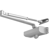
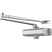
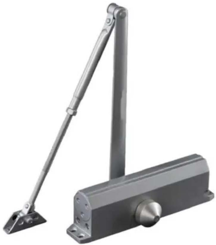
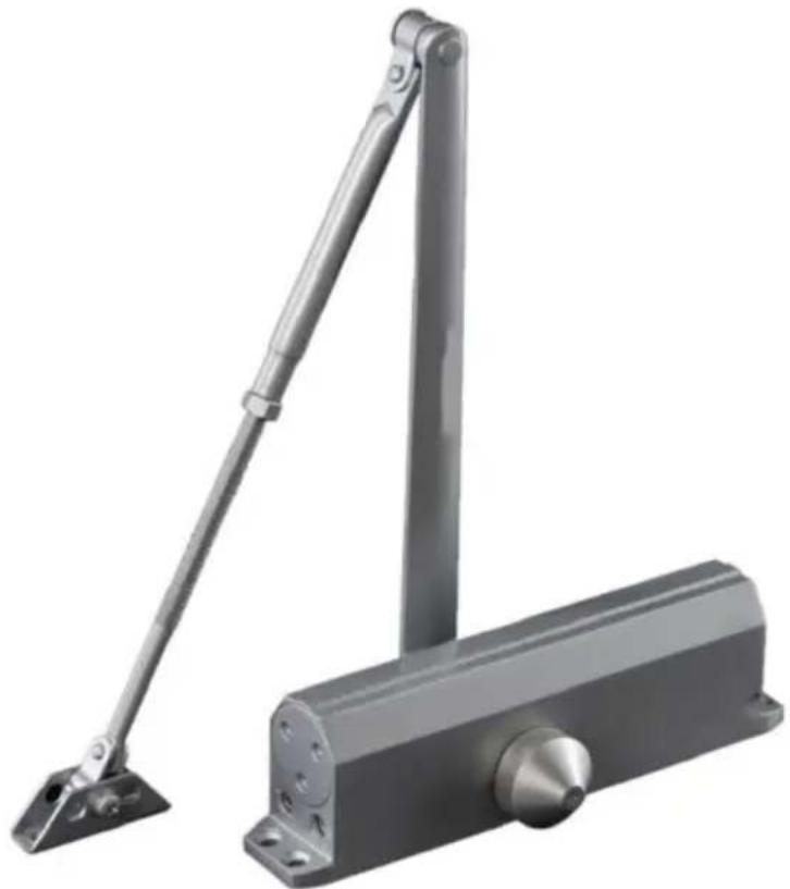
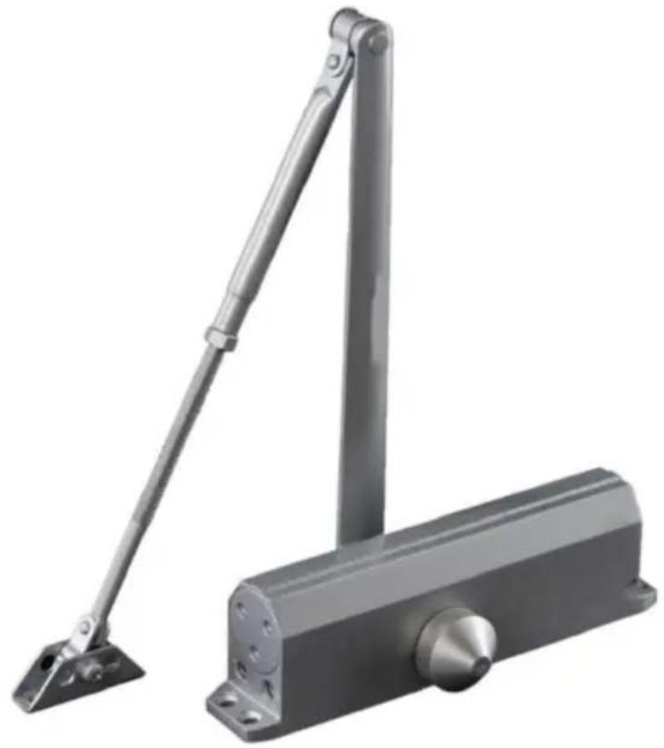
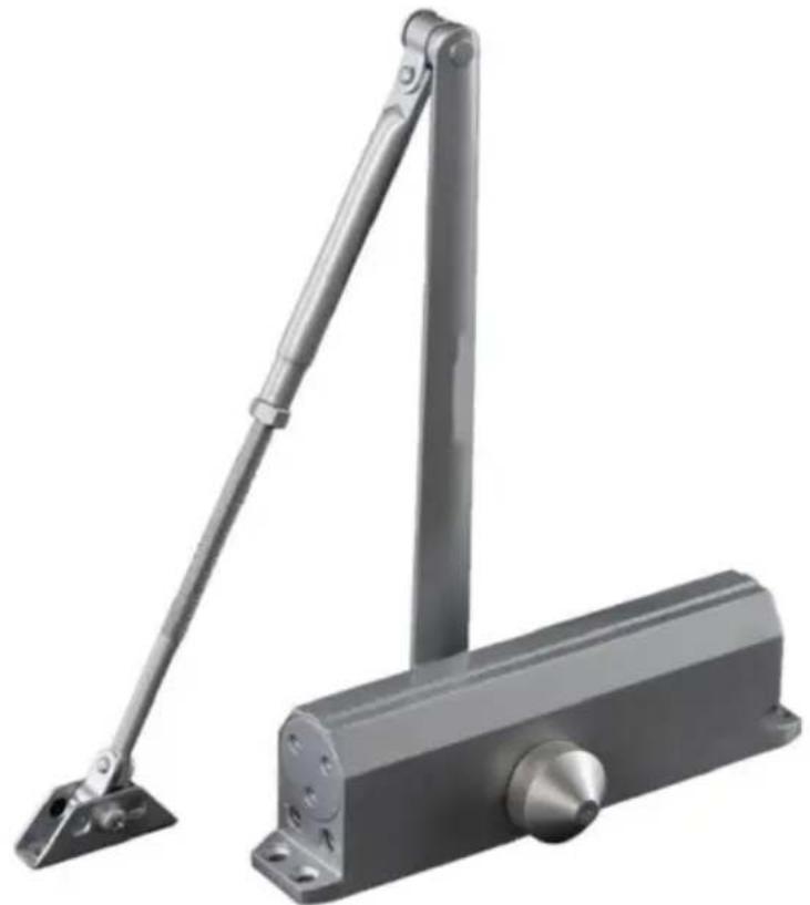
DOOR CLOSER
MODEL:D4015 / D4016
We continue to be committed to provide you tools with competitive price. "Save Half", "Half Price" or any other similar expressions used by us only represent estimate of savings you might benefit from buying certain tools with us compared top brands and does not necessarily mean to cover all categories of tools offered are kindly reminded to verify carefully when you are placing an order with us actually saving half in comparison with the top major brands.
VEVOR®
TOUGH TOOLS, HALF PRICE
DOOR CLOSER
MODEL: D4015 / D4016
natural_image
Metallic hand-operated door lock with adjustable lever and base (no text or symbols visible)NEED HELP? CONTACT US!
Have product questions? Need technical support? Please feel fr contact us:
Technical Support and E-Warranty Certificate www.vevor.com/support
This is the original instruction, please read all manual instruction carefully before operating. VEVOR reserves a clear interpretation user manual. The appearance of the product shall be subject to product you received. Please forgive us that we won't inform you there are any technology or software updates on our product.
WARNING:
- Do not allow children to climb on the unit.
- Keep children and pets away during assembly.
ASSEMBLY PRECAUTIONS
- Please assemble the product in strict accordance with the instructic Incorrect assembly could be hazardous.
- Please wear safety goggles and work gloves properly during assem
- Do not try to assemble the product when feeling tired or when ur influence of alcohol, drugs or medication.
- Load bearing capacity and other product parameters are applied to properly and completely assembled product only.
- Separate and count all parts and hardware.
- Prepare the following tool: Philips Head Screwdriver.
- If using power tools, please be careful to slow down and stop with needed.
- Two people are required for assembly.
- Follow the intended uses only.
- Use on stable surfaces only.
- Regularly inspect for signs of wear, damage, or loose parts.
SAVE THESE INSTRUCTIONS
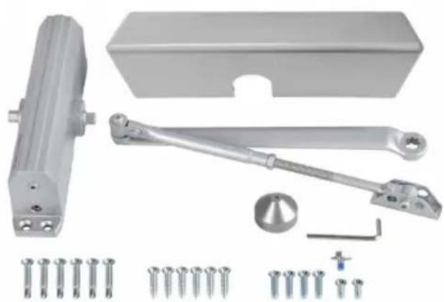
PART LIST
When unpacking this product, check to make sure the parts listed be are included and carefully inspect for any damage that may have occurred during transit. If any part is missing or damaged, do not attempt to assemble or use the product.
natural_image
Collection of mechanical components including a sliding contactor, bracket, and screw assembly (no text or symbols visible)
natural_image
Collection of black mechanical components including a sliding contactor, bracket, and screw fasteners (no text or symbols visible)| NO | PICTURE | PART NAME | QTY |
| A |  | Door closer body | 1 |
| B | 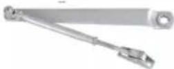 | HO Arm | 1 |
| C | 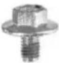 | Rocker Arm Bolt M6×10 | 1 |
| D | 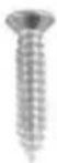 | Wooden Doors Screw ST6.3×30 | 6 |
| E | 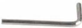 | Hex Wrench | 1 |
| F | [74CC] | Self-tapping Screw ST6.3×38 | 6 |
| G |  | Metal Doors Screw 1/4-20×16 | 2 |
| H | [468C] | Metal Doors Screw 1/4-20×25 | 4 |
| I |  | Pinion Cap | 1 |
| J |  | Plastic Cover | 1 |
PRODUCT PAREMETERS
| Model | D4015 | D4016 |
| Material | Aluminum | Aluminum |
| Color | Silvery or Black | Silvery or Black |
| Door Max Load T Use | 265 lbs | 330 lbs |
INSTALLATION AND OPERATION INSTRUCTIONS
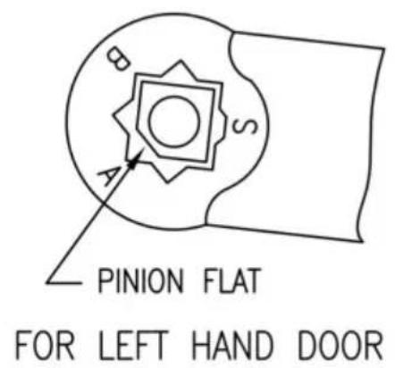
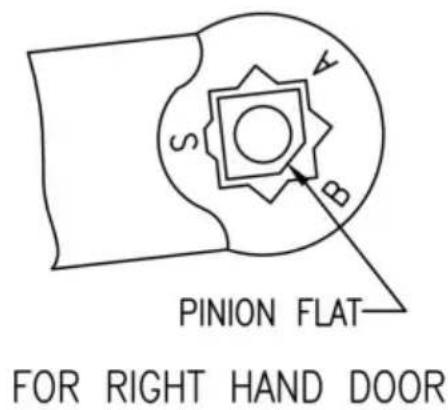
- Chart to determine hand of door.
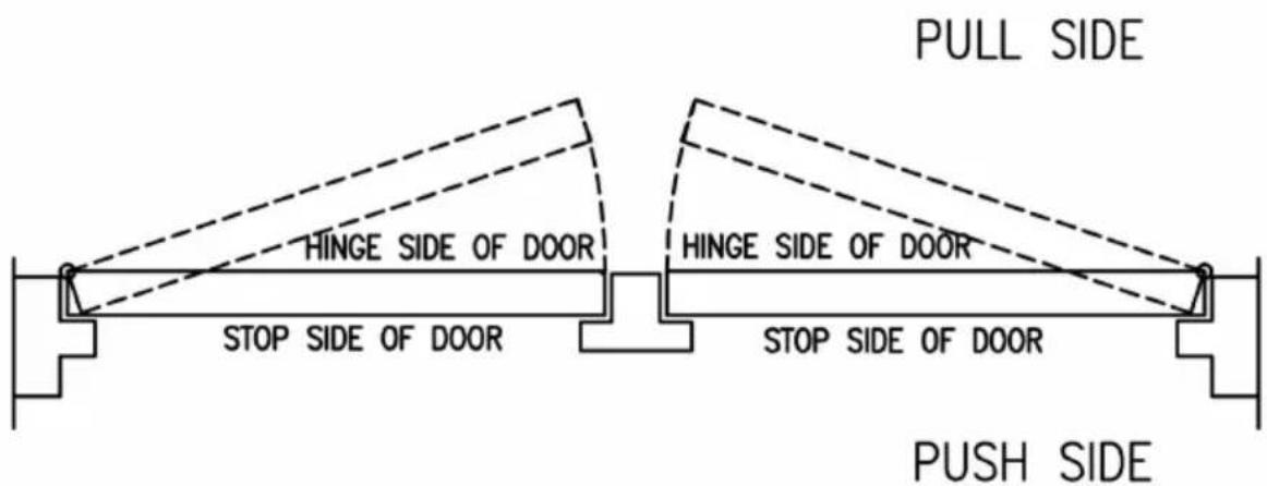
THIS IS A LEFT HAND DOOR
THIS IS A RIGHT HAND DOOR
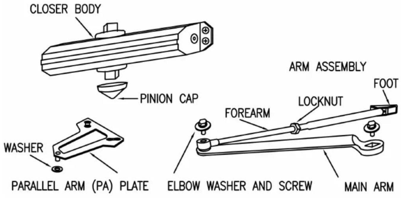
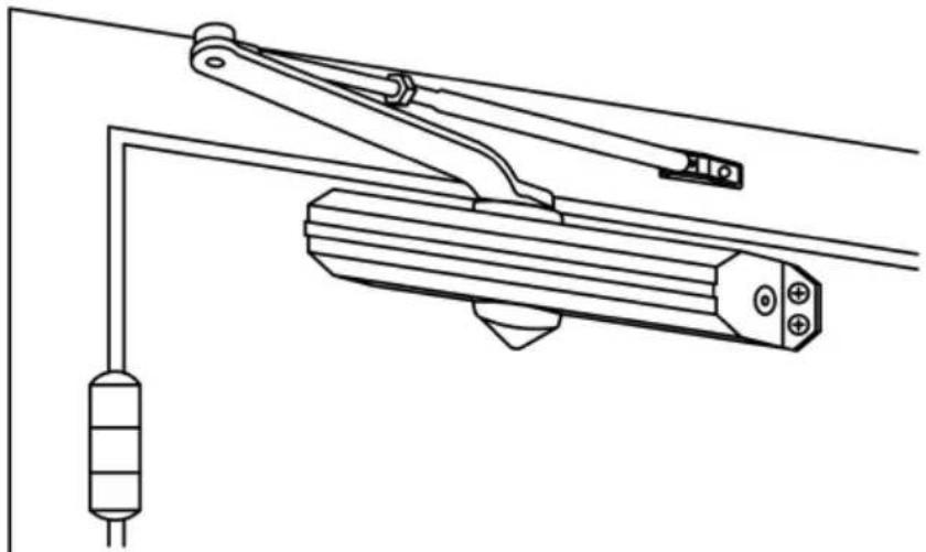
2.Components.
3. Control Function.
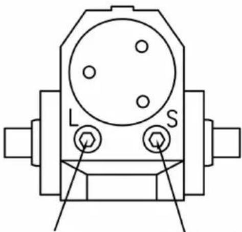
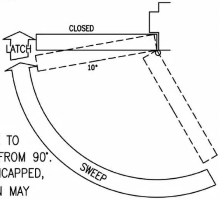
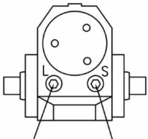
CLOSING SPEED CONTROL
CAUTION DO NOT BACK VALVES OUT OF CLOSER OR A LEAK WILL RESULT
ATTENTION:
ADJUST CLOSING SPEED TIME TO BETWEEN 4 TO 6 SECONDS FROM 90°. USE OF THE DOOR BY HANDICAPPED, ELDERLY OR SMALL CHILDREN MAY REQUIRE LONGER CLOSING TIME.
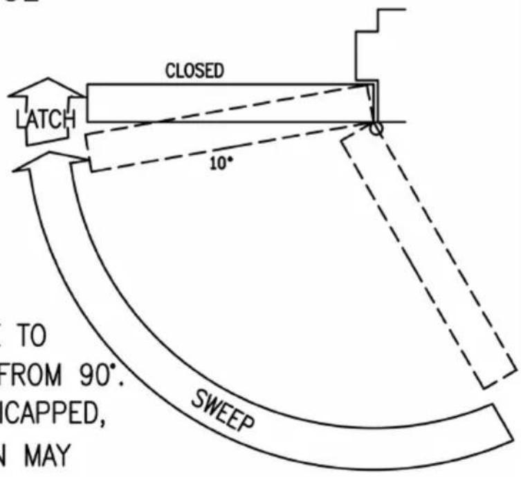
STANDARD CLOSING CYCLE
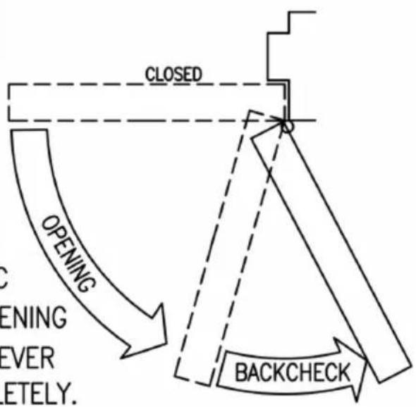
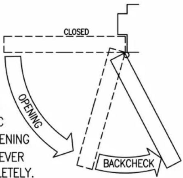
OPENING DOOR CONTROL
CAUTION
DO NOT BACK VALVES OUT OF
CLOSER OR A LEAK WILL RESULT
ATTENTION:
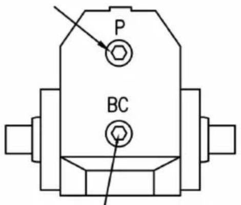
BACKCHECK ("BC") VALVE
CONTROLS THE HYDRAULIC
RESISTANCE TO DOOR OPENING
IN BACKCHECK RANGE. NEVER
CLOSE THIS VALVE COMPLETELY.
IT IS NOT TO PROVIDE A POSITIVE STOP.

flowchart
graph TD
    A["OPENING"] --> B["CLOSED"]
    B --> C["BACKCHECK"]
    C --> D["STOP"]
    style A fill:#f9f,stroke:#333
    style B fill:#ccf,stroke:#333
    style C fill:#cfc,stroke:#333
    style D fill:#fcc,stroke:#333
4. Final adjustment and regulating procedures.
REGULATING DOOR SPEED AND LATCHING SPEED
TURN SPEED REGULATING VALVE CLOCKWISE TO SLOW DOWN OR COUNTER CLOCKWISE TO SPEED UP DOOR MOVEMENT

THIS VAVLE CONTROLS LATCHING SPEED
THIS VAVLE CONTROLS DOOR SWEEP SPEED
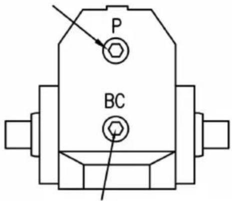
REGULATING SPRING POWER REGULATING BC POWER
POWER ADJUSTMENT SCREW. TURN THIS SCREW CLOCKWISE TO INCREASE OR COUNTER CLOCKWISE TO DECREASE.

TURN BC REGULATING VALVE CLOCKWISE TO INCREASE OR COUNTER CLOCKWISE TO DECREASE. NEVER CLOSE THIS VALVE COMPLETELY.
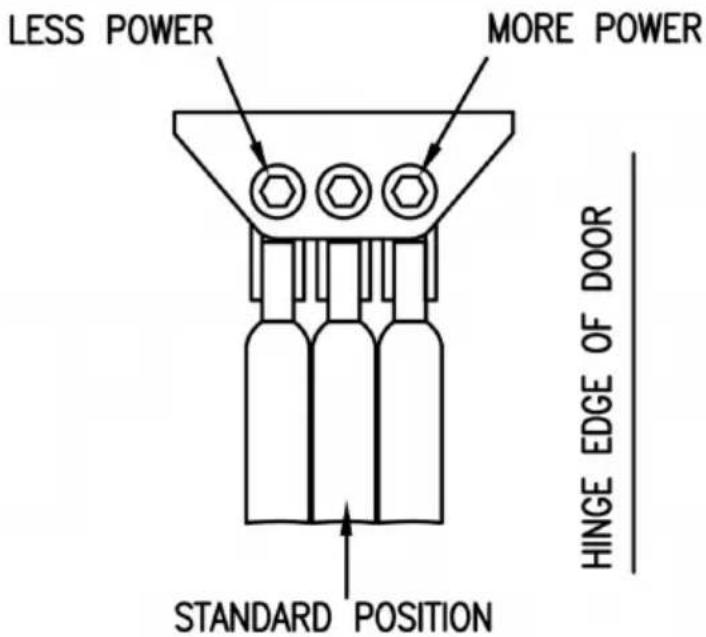
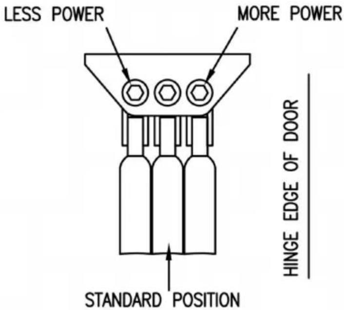
ADJUSTING FOOT FOR CLOSING POWER
MOVE FOOT PIVOT TO HOLE AS ILLUSTRATED BELOW

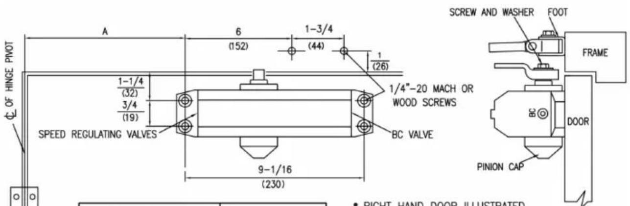
5. Regular Arm installation.
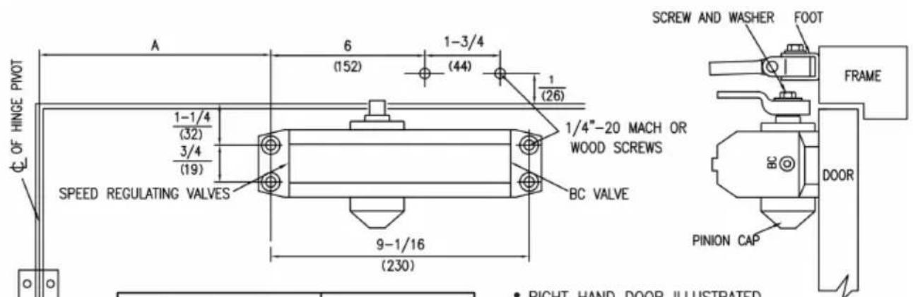
| DIMENSIONS "A" | OPENING | |
| inches | mm | |
| 7 | 178 | T100° |
| 6 | 152 | 101°T0120° |
| 3-1/2 | 89 | *121°T0180° |
• RIGHT HAND DOOR ILLUSTRATED SAME DIMENSIONS APPLY TO LEFT HAND DOOR
• MEASURED FROM HINGE € DIMENSIONS ARE IN inches (mm)
• DO NOT SCALE DRAWING
* Door/Wall/Hardware/Jamb conditions permitting
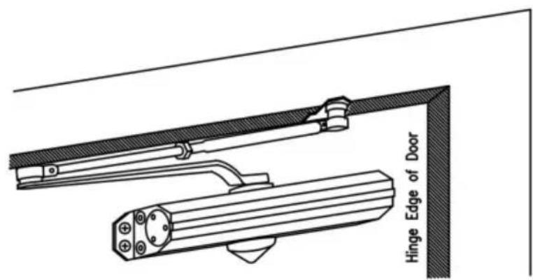
Installation Instructions
- Select degree of door. Use dimensions shown in chart and illustrate above to mark location of attaching screws on door and frame holes.
- Assemble main arm to closer.
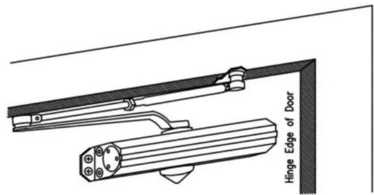
- Attach closer to door with speed regulating valves toward hing
- Attach the foot of the forearm to frame.
- Adjust length of forearm to position forearm at right angle to when connected to main arm at elbow use washer and screw secure pivot connection. Tighten lock nut on forearm.
- Snap pinion cap over spindle at bottom of closer.
- Adjust closer.
natural_image
Technical line drawing of a mechanical device with a cylindrical component attached to its side (no text or symbols)The chart is suitable for power adjustment door closer.
| MAXIMUM DOOR WIDTH | FULL TURNS REQUIRED | |
| EXTERIOR DOORS | INTERIOR DOORS | |
| —— | 5 lb-f* | 13 TURNS C.C.W. |
| 8.5 lb-f* | 34" (864) | 9 TURNS C.C.W. |
| 30" (762) | 38" (962) | 5 TURNS C.C.W. |
| 36" (914) | 48" (1219) | 0 TURNS |
| 42" (1067) | 54" (1372) | 5 TURNS C.W. |
| 48" (1219) | 60" (1524) | 10 TURNS C.W. |
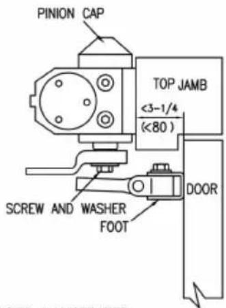
6.Top JAMB installation
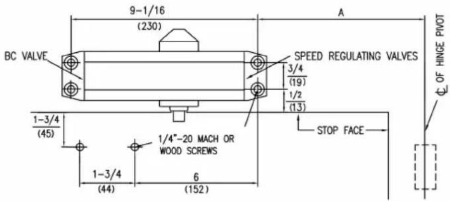
| DIMENSIONS "A" | OPENING | |
| inches | mm | |
| 7-1/2 | 191 | T100° |
| 6 | 152 | 101°TO120° |
| 3-1/2 | 89 | *121°TO180° |
* Door/Wall/Hardware/Jamb conditions permitting
• RIGHT HAND DOOR ILLUSTRATED
SAME DIMENSIONS APPLY TO LEFT HAND DOOR
• MEASURED FROM HINGE €
DIMENSIONS ARE IN inches (mm)
• DO NOT SCALE DRAWING
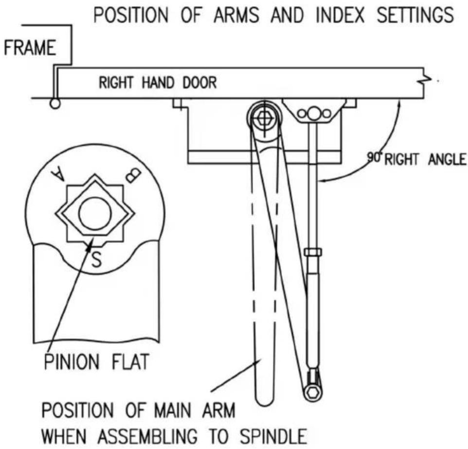
Position of arms and index settings
POSITION OF MAIN ARM
WHEN ASSEMBLING TO SPINDLE
Installation instructions
- Select degree of door. Use dimensions shown in chart and illustratic above to mark location of attaching screws on door and frame prepar holes.
- Assemble main arm to closer.
- Attach closer to frame with speed regulating valves toward hinge.
- Attach the foot of the forearm to door.
- Adjust length of forearm to position forearm at right angle to frame connected to main arm at elbow use washer and screw provided to pivot connection. Tighten lock nut on forearm.
- Snap pinion cap over spindle at bottom of closer.
- Adjust closer.
natural_image
Technical line drawing of a mechanical assembly with rollers and levers (no text or symbols)About Power Adjustment
Before installation, Adjust the spring power as chart in page 2. Adjust spring power DO NOT exceed the maximum turn.
The spring power has been reset on 0 turns in factory.
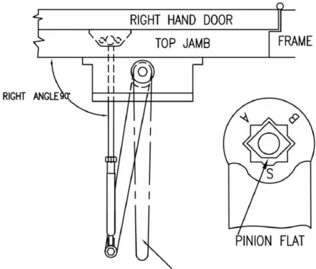
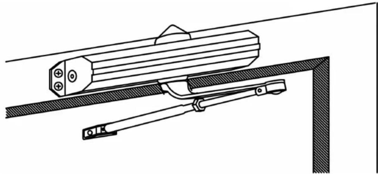
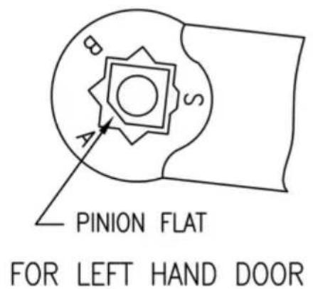
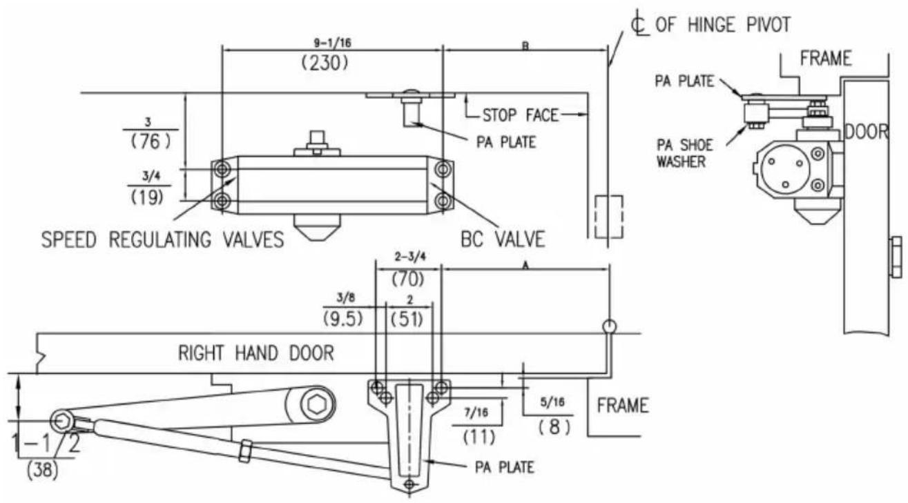
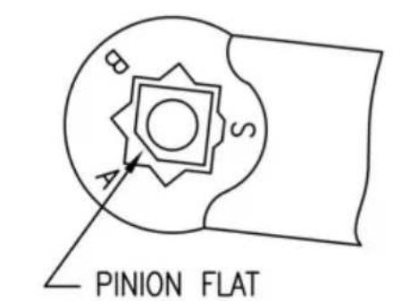
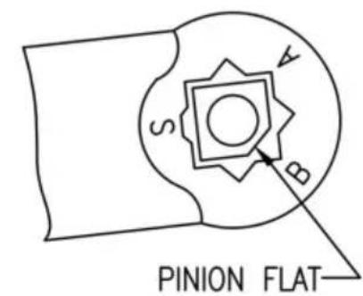
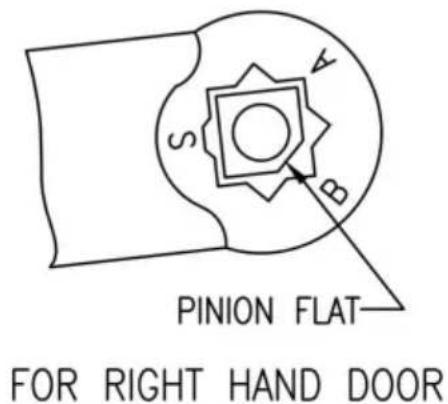
7. Parallel arm installation
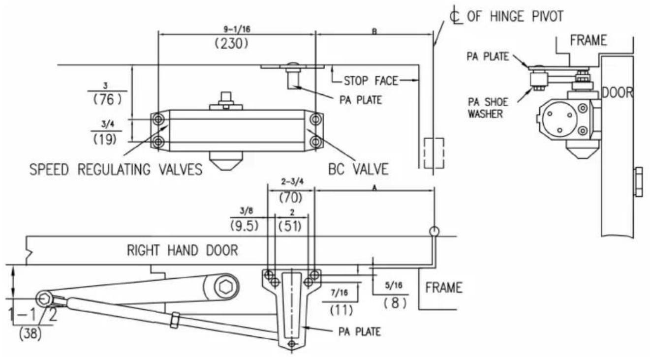
• RIGHT HAND DOOR ILLUSTRATED
SAME DIMENSIONS APPLY TO LEFT HAND DOOR
• MEASURED FROM HINGE Ⓒ
DIMENSIONS ARE IN inches (mm)
• DO NOT SCALE DRAWING
| DIMENSIONS "A" | DIMENSIONS "B" | OPENING | ||
| inches | mm | inches | mm | |
| 9-1/4 | 235 | 7-5/8 | 194 | TO 100° |
| 7-3/4 | 197 | 6-1/8 | 156 | 101° TO 150° |
| 5-3/4 | 146 | 4-1/8 | 105 | OVER 151° |

Installation instructions
-
Select degree of door.use dimensions shown in chart and illustration above to mark location of attaching screws on door and frame prepar holes.
-
Attach closer to door with speed regulating valves back to hinge.
-
Attach pa plate to top frame as shown
-
Remove foot from forearm and discard.
-
Install arm on pinion shaft. rotate pinion 45^ toward hinge edge of door align main arm letter "B"(right hand door) or "A"(left hand door) with p flat.fasten with arm screw.
-
Fasten forearm to pa plate using screw removed from foot in step pa shoe washer included in screw pack.
-
Adjust forearm length to set arm elbow about 1-1/2"(38mm) from do when connected to main arm. use washer and screw provided to secu pivot connection. Tighten lock nut.
-
Snap pinion cap over spindle at bottom
-
Adjust closer.
Manufacturer: Shanghaimuxinmuyeyouxiangongsi
Address: Baoshanqu Shuangchenglu 803long 11hao 1602A-1609shi Shanghai
Imported to AUS:SIHAO PTY LTD.1 ROKEVA STREETEASTWOOD NSW 2122 Australia
Imported to USA: Sanven Technology Ltd. Suite 250,9166 Anaheim Place, Rancho Cucamonga, CA91730
Pooledas Group Ltd
| UK | REP |
Unit 5 Albert Edward House,
The Pavilions Preston, United Kingdom
pooledas123@gmail.com
01772418127
| EC | REP |
SHUNSHUN GmbH
Römeräcker 9 Z2021,76351
Technical Support and E-Warranty Certificate
www.vevor.com/support
Made In China
VEVOR®
TOUGH TOOLS, HALF PRICE
We continue to be committed to provide you tools with competitive price. "Save Half", "Half Price" or any other similar expressions used by us only represent estimate of savings you might benefit from buying certain tools with us compared top brands and does not necessarily mean to cover all categories of tools offered are kindly reminded to verify carefully when you are placing an order with us actually saving half in comparison with the top major brands.
VEVOR®
TOUGH TOOLS, HALF PRICE
DOOR CLOSER
MODÈLE : D4015 / D4016
natural_image
Metallic hand-operated door lock device with adjustable lever and base (no text or symbols visible)NEED HELP? CONTACT US!
Have product questions? Need technical support? Please feel fr contact us:
Technical Support and E-Warranty Certificate www.vevor.com/support
This is the original instruction, please read all manual instruction carefully before operating. VEVOR reserves a clear interpretation user manual. The appearance of the product shall be subject to product you received. Please forgive us that we won't inform you there are any technology or software updates on our product.
AVERTISSEMENT:
natural_image
Collection of mechanical components including a sliding contactor, lever handle, and screw fasteners (no text or symbols visible)
natural_image
Collection of black automotive components including a lock, handle, screwdriver, and bolts (no text or symbols visible)STANDARD CLOSING CYCLE
OPENING DOOR CONTROL
CAUTION
DO NOT BACK VALVES OUT OF
CLOSER OR A LEAK WILL RESULT
ATTENTION:
BACKCHECK ("BC") VALVE
CONTROLS THE HYDRAULIC
RESISTANCE TO DOOR OPENING
IN BACKCHECK RANGE. NEVER
CLOSE THIS VALVE COMPLETELY.
IT IS NOT TO PROVIDE A POSITIVE STOP.

flowchart
graph TD
    A["OPENING"] --> B["CLOSED"]
    B --> C["BACKCHECK"]
    C --> D["STOP"]
    style A fill:#f9f,stroke:#333
    style B fill:#ccf,stroke:#333
    style C fill:#cfc,stroke:#333
    style D fill:#fcc,stroke:#333
TURN SPEED REGULATING VALVE CLOCKWISE TO SLOW DOWN OR COUNTER CLOCKWISE TO SPEED UP DOOR MOVEMENT
THIS VAVLE CONTROLS LATCHING SPEED
THIS VAVLE CONTROLS DOOR SWEEP SPEED
REGULATING SPRING POWER REGULATING BC POWER
POWER ADJUSTMENT SCREW. TURN THIS SCREW CLOCKWISE TO INCREASE OR COUNTER CLOCKWISE TO DECREASE.

TURN BC REGULATING VALVE CLOCKWISE TO INCREASE OR COUNTER CLOCKWISE TO DECREASE. NEVER CLOSE THIS VALVE COMPLETELY.
ADJUSTING FOOT FOR CLOSING POWER
MOVE FOOT PIVOT TO HOLE AS ILLUSTRATED BELOW

• RIGHT HAND DOOR ILLUSTRATED SAME DIMENSIONS APPLY TO LEFT HAND DOOR
• MEASURED FROM HINGE € DIMENSIONS ARE IN inches (mm)
• DO NOT SCALE DRAWING
* Door/Wall/Hardware/Jamb conditions permitting

natural_image
Technical line drawing of a mechanical device with a cylindrical component attached to its side (no text or symbols)• RIGHT HAND DOOR ILLUSTRATED
SAME DIMENSIONS APPLY TO LEFT HAND DOOR
• MEASURED FROM HINGE €
DIMENSIONS ARE IN inches
(mm)
• DO NOT SCALE DRAWING
* Door/Wall/Hardware/Jamb conditions permitting
natural_image
Technical line drawing of a mechanical assembly with no visible text or symbolsAbout Power Adjustment
Before installation, Adjust the spring power as chart in page 2. Adjust spring power DO NOT exceed the maximum turn.
The spring power has been reset on 0 turns in factory.
• RIGHT HAND DOOR ILLUSTRATED
SAME DIMENSIONS APPLY TO LEFT HAND DOOR
• MEASURED FROM HINGE ♦
DIMENSIONS ARE IN inches (mm)
• DO NOT SCALE DRAWING
| DIMENSIONS "A" | DIMENSIONS "B" | OPENING | ||
| inches | mm | inches | mm | |
| 9-1/4 | 235 | 7-5/8 | 194 | TO 100° |
| 7-3/4 | 197 | 6-1/8 | 156 | 101° TO 150° |
| 5-3/4 | 146 | 4-1/8 | 105 | OVER 151° |

Unit 5 Albert Edward House,
The Pavilions Preston, United Kingdom
pooledas123@gmail.com
01772418127
| EC | REP |
SHUNSHUN GmbH
Römeräcker 9 Z2021,76351
www.vevor.com/support
Fabriqué en Chine
VEVOR®
TOUGH TOOLS, HALF PRICE
We continue to be committed to provide you tools with competitive price. "Save Half", "Half Price" or any other similar expressions used by us only represent estimate of savings you might benefit from buying certain tools with us compared top brands and does not necessarily mean to cover all categories of tools offered are kindly reminded to verify carefully when you are placing an order with us actually saving half in comparison with the top major brands.
VEVOR®
TOUGH TOOLS, HALF PRICE
DOOR CLOSER
MODELL : D4015 / D4016

natural_image
Metallic hand-operated door lock device with adjustable lever and base (no text or symbols visible)NEED HELP? CONTACT US!
Have product questions? Need technical support? Please feel fr contact us:
Technical Support and E-Warranty Certificate www.vevor.com/support
This is the original instruction, please read all manual instruction carefully before operating. VEVOR reserves a clear interpretation user manual. The appearance of the product shall be subject to product you received. Please forgive us that we won't inform you there are any technology or software updates on our product.
WARNUNG:
natural_image
Collection of mechanical components including a sliding contactor, bracket, wrench, and screw fasteners (no text or symbols visible)
natural_image
Collection of black automotive door lock components including a sliding contact, handle, and screw base (no text or symbols visible)DO NOT BACK VALVES OUT OF CLOSER OR A LEAK WILL RESULT
STANDARD CLOSING CYCLE
ATTENTION:
ADJUST CLOSING SPEED TIME TO BETWEEN 4 TO 6 SECONDS FROM 90°. USE OF THE DOOR BY HANDICAPPED, ELDERLY OR SMALL CHILDREN MAY REQUIRE LONGER CLOSING TIME.
OPENING DOOR CONTROL
CAUTION
DO NOT BACK VALVES OUT OF CLOSER OR A LEAK WILL RESULT
flowchart
graph TD
    A["OPENING"] --> B["CLOSED"]
    B --> C["BACKCHECK"]
    style A fill:#f9f,stroke:#333
    style C fill:#ccf,stroke:#333
ATTENTION:
BACKCHECK ("BC") VALVE CONTROLS THE HYDRAULIC RESISTANCE TO DOOR OPENING IN BACKCHECK RANGE. NEVER CLOSE THIS VALVE COMPLETELY
IT IS NOT TO PROVIDE A POSITIVE STOP.
TURN SPEED REGULATING VALVE CLOCKWISE TO SLOW DOWN OR COUNTER CLOCKWISE TO SPEED UP DOOR MOVEMENT
THIS VAVLE CONTROLS LATCHING SPEED
THIS VAVLE CONTROLS DOOR SWEEP SPEED
REGULATING SPRING POWER REGULATING BC POWER
POWER ADJUSTMENT SCREW. TURN THIS SCREW CLOCKWISE TO INCREASE OR COUNTER CLOCKWISE TO DECREASE.
TURN BC REGULATING VALVE CLOCKWISE TO INCREASE OR COUNTER CLOCKWISE TO DECREASE. NEVER CLOSE THIS VALVE COMPLETELY.
ADJUSTING FOOT FOR CLOSING POWER
MOVE FOOT PIVOT TO HOLE AS ILLUSTRATED BELOW
* Door/Wall/Hardware/Jamb conditions permitting

natural_image
Technical line drawing of a mechanical lever system with a cylindrical component attached (no text or symbols)• RIGHT HAND DOOR ILLUSTRATED SAME DIMENSIONS APPLY TO LEFT HAND DOOR
• MEASURED FROM HINGE ♦ DIMENSIONS ARE IN inches (mm)
• DO NOT SCALE DRAWING
* Door/Wall/Hardware/Jamb conditions permitting
natural_image
Technical line drawing of a mechanical assembly with no visible text or symbolsAbout Power Adjustment
Before installation, Adjust the spring power as chart in page 2. Adjust spring power DO NOT exceed the maximum turn.
The spring power has been reset on 0 turns in factory.
9. Parallelarminstallation
• RIGHT HAND DOOR ILLUSTRATED
SAME DIMENSIONS APPLY TO LEFT HAND DOOR
• MEASURED FROM HINGE ♦
DIMENSIONS ARE IN (mm)
• DO NOT SCALE DRAWING
| DIMENSIONS "A" | DIMENSIONS "B" | OPENING | ||
| inches | mm | inches | mm | |
| 9-1/4 | 235 | 7-5/8 | 194 | TO 100° |
| 7-3/4 | 197 | 6-1/8 | 156 | 101° TO 150° |
| 5-3/4 | 146 | 4-1/8 | 105 | OVER 151° |
FOR LEFT HAND DOOR
FOR RIGHT HAND DOOR
Unit 5 Albert Edward House,
The Pavilions Preston, United Kingdom
pooledas123@gmail.com
01772418127
| EC | REP |
SHUNSHUN GmbH
Römeräcker 9 Z2021,76351
www.vevor.com/support
We continue to be committed to provide you tools with competitive price. "Save Half", "Half Price" or any other similar expressions used by us only represent estimate of savings you might benefit from buying certain tools with us compared top brands and does not necessarily mean to cover all categories of tools offered are kindly reminded to verify carefully when you are placing an order with us actually saving half in comparison with the top major brands.
VEVOR®
TOUGH TOOLS, HALF PRICE
DOOR CLOSER
MODELLO : D4015 / D4016
natural_image
Metallic industrial lock handle with adjustable arm and base (no text or symbols visible)NEED HELP? CONTACT US!
Have product questions? Need technical support? Please feel fr contact us:
Technical Support and E-Warranty Certificate www.vevor.com/support
This is the original instruction, please read all manual instruction carefully before operating. VEVOR reserves a clear interpretation user manual. The appearance of the product shall be subject to product you received. Please forgive us that we won't inform you there are any technology or software updates on our product.
AVVERTIMENTO:
natural_image
Collection of industrial mechanical components including a sliding door, bracket, and tools (no text or symbols visible)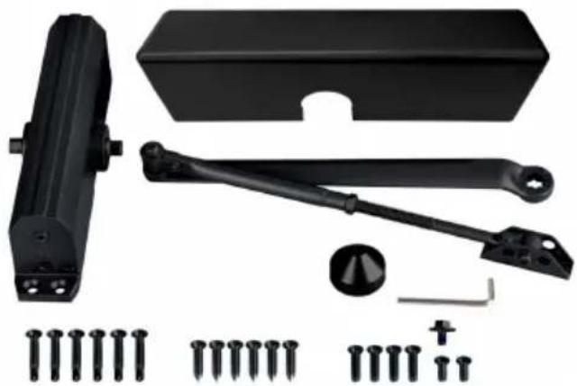
natural_image
Collection of black mechanical components including a lock, bracket, and screws (no text or symbols visible)| NO | IMMAGINE | NOME DELLA PARTE | QUAN TITÀ |
| UN | 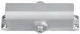 | Corpo chiudiporta | 1 |
| B | 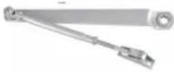 | Braccio HO | 1 |
| C | 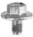 | Bullone del bilanciere M6×10 | 1 |
| D |  | per Porte in Legno ST6.3×30 | 6 |
| E |  | Chiave esagonale | 1 |
| F | [6HZ] | Vite Autofilettante ST6.3×38 | 6 |
| G |  | per porte in metallo 1/4-20×16 | 2 |
| H | [6ZY2] | Porte in metallo Vite 1/4-20×25 | 4 |
| IO |  | Tappo pignone | 1 |
STANDARD CLOSING CYCLE
OPENING DOOR CONTROL
CAUTION
DO NOT BACK VALVES OUT OF
CLOSER OR A LEAK WILL RESULT
ATTENTION:
BACKCHECK ("BC") VALVE
CONTROLS THE HYDRAULIC
RESISTANCE TO DOOR OPENING
IN BACKCHECK RANGE. NEVER
CLOSE THIS VALVE COMPLETELY.
IT IS NOT TO PROVIDE A POSITIVE STOP.

flowchart
graph TD
    A["OPENING"] --> B["CLOSED"]
    B --> C["BACKCHECK"]
    C --> D["STOP"]
    style A fill:#f9f,stroke:#333
    style B fill:#ccf,stroke:#333
    style C fill:#cfc,stroke:#333
    style D fill:#fcc,stroke:#333
TURN SPEED REGULATING VALVE CLOCKWISE TO SLOW DOWN OR COUNTER CLOCKWISE TO SPEED UP DOOR MOVEMENT

THIS VAVLE CONTROLS LATCHING SPEED
THIS VAVLE CONTROLS DOOR SWEEP SPEED
REGULATING SPRING POWER REGULATING BC POWER
POWER ADJUSTMENT SCREW. TURN THIS SCREW CLOCKWISE TO INCREASE OR COUNTER CLOCKWISE TO DECREASE.

TURN BC REGULATING VALVE CLOCKWISE TO INCREASE OR COUNTER CLOCKWISE TO DECREASE. NEVER CLOSE THIS VALVE COMPLETELY.
ADJUSTING FOOT FOR CLOSING POWER
MOVE FOOT PIVOT TO HOLE AS ILLUSTRATED BELOW
• RIGHT HAND DOOR ILLUSTRATED SAME DIMENSIONS APPLY TO LEFT HAND DOOR
• MEASURED FROM HINGE € DIMENSIONS ARE IN inches (mm)
• DO NOT SCALE DRAWING
* Door/Wall/Hardware/Jamb conditions permitting

natural_image
Technical line drawing of a mechanical lever system with a cylindrical component attached (no text or symbols)• RIGHT HAND DOOR ILLUSTRATED
SAME DIMENSIONS APPLY TO LEFT HAND DOOR
• MEASURED FROM HINGE €
DIMENSIONS ARE IN inches (mm)
• DO NOT SCALE DRAWING
* Door/Wall/Hardware/Jamb conditions permitting
natural_image
Technical line drawing of a mechanical assembly with no visible text or symbolsAbout Power Adjustment
Before installation, Adjust the spring power as chart in page 2. Adjust spring power DO NOT exceed the maximum turn.
The spring power has been reset on 0 turns in factory.
• RIGHT HAND DOOR ILLUSTRATED
SAME DIMENSIONS APPLY TO LEFT HAND DOOR
• MEASURED FROM HINGE ♦
DIMENSIONS ARE IN inches (mm)
• DO NOT SCALE DRAWING
| DIMENSIONS "A" | DIMENSIONS "B" | OPENING | ||
| inches | mm | inches | mm | |
| 9-1/4 | 235 | 7-5/8 | 194 | TO 100° |
| 7-3/4 | 197 | 6-1/8 | 156 | 101° TO 150° |
| 5-3/4 | 146 | 4-1/8 | 105 | OVER 151° |


Unit 5 Albert Edward House,
The Pavilions Preston, United Kingdom
pooledas123@gmail.com
01772418127
| EC | REP |
SHUNSHUN GmbH
Römeräcker 9 Z2021,76351
www.vevor.com/support
Made in China
VEVOR®
TOUGH TOOLS, HALF PRICE
We continue to be committed to provide you tools with competitive price. "Save Half", "Half Price" or any other similar expressions used by us only represent estimate of savings you might benefit from buying certain tools with us compared top brands and does not necessarily mean to cover all categories of tools offered are kindly reminded to verify carefully when you are placing an order with us actually saving half in comparison with the top major brands.
VEVOR®
TOUGH TOOLS, HALF PRICE
DOOR CLOSER
MODELO : D4015 / D4016

natural_image
Metallic hand-operated door lock device with adjustable lever and base (no text or symbols visible)NEED HELP? CONTACT US!
Have product questions? Need technical support? Please feel fr contact us:
Technical Support and E-Warranty Certificate www.vevor.com/support
This is the original instruction, please read all manual instruction carefully before operating. VEVOR reserves a clear interpretation user manual. The appearance of the product shall be subject to product you received. Please forgive us that we won't inform you there are any technology or software updates on our product.
ADVERTENCIA:
STANDARD CLOSING CYCLE
OPENING DOOR CONTROL
CAUTION
DO NOT BACK VALVES OUT OF
CLOSER OR A LEAK WILL RESULT
ATTENTION:
BACKCHECK ("BC") VALVE
CONTROLS THE HYDRAULIC
RESISTANCE TO DOOR OPENING
IN BACKCHECK RANGE. NEVER
CLOSE THIS VALVE COMPLETELY.
IT IS NOT TO PROVIDE A POSITIVE STOP.

flowchart
graph TD
    A["OPENING"] --> B["CLOSED"]
    B --> C["BACKCHECK"]
    C --> D["STOP"]
    style A fill:#f9f,stroke:#333
    style B fill:#ccf,stroke:#333
    style C fill:#cfc,stroke:#333
    style D fill:#fcc,stroke:#333
TURN SPEED REGULATING VALVE CLOCKWISE TO SLOW DOWN OR COUNTER CLOCKWISE TO SPEED UP DOOR MOVEMENT

THIS VAVLE CONTROLS LATCHING SPEED
THIS VAVLE CONTROLS DOOR SWEEP SPEED
REGULATING SPRING POWER REGULATING BC POWER
POWER ADJUSTMENT SCREW. TURN THIS SCREW CLOCKWISE TO INCREASE OR COUNTER CLOCKWISE TO DECREASE.

TURN BC REGULATING VALVE CLOCKWISE TO INCREASE OR COUNTER CLOCKWISE TO DECREASE. NEVER CLOSE THIS VALVE COMPLETELY.
ADJUSTING FOOT FOR CLOSING POWER
MOVE FOOT PIVOT TO HOLE AS ILLUSTRATED BELOW

• RIGHT HAND DOOR ILLUSTRATED SAME DIMENSIONS APPLY TO LEFT HAND DOOR
• MEASURED FROM HINGE € DIMENSIONS ARE IN inches (mm)
• DO NOT SCALE DRAWING
* Door/Wall/Hardware/Jamb conditions permitting

natural_image
Technical line drawing of a mechanical device with a cylindrical component attached to a rod (no text or symbols)• RIGHT HAND DOOR ILLUSTRATED
SAME DIMENSIONS APPLY TO LEFT HAND DOOR
• MEASURED FROM HINGE ♦
DIMENSIONS ARE IN inches (mm)
• DO NOT SCALE DRAWING
* Door/Wall/Hardware/Jamb conditions permitting
natural_image
Technical line drawing of a mechanical assembly with no visible text or symbolsAbout Power Adjustment
Before installation, Adjust the spring power as chart in page 2. Adjust spring power DO NOT exceed the maximum turn.
The spring power has been reset on 0 turns in factory.
• RIGHT HAND DOOR ILLUSTRATED
SAME DIMENSIONS APPLY TO LEFT HAND DOOR
• MEASURED FROM HINGE ♦
DIMENSIONS ARE IN inches (mm)
• DO NOT SCALE DRAWING
| DIMENSIONS "A" | DIMENSIONS "B" | OPENING | ||
| inches | mm | inches | mm | |
| 9-1/4 | 235 | 7-5/8 | 194 | TO 100° |
| 7-3/4 | 197 | 6-1/8 | 156 | 101° TO 150° |
| 5-3/4 | 146 | 4-1/8 | 105 | OVER 151° |


Lugar, Rancho Cucamonga, CA91730
| UK | REP |
Pooledas Group Ltd
Unit 5 Albert Edward House,
The Pavilions Preston, United Kingdom
pooledas123@gmail.com
01772418127
| EC | REP |
SHUNSHUN GmbH
Römeräcker 9 Z2021,76351
www.vevor.com/support
Hecho en china
VEVOR®
TOUGH TOOLS, HALF PRICE
We continue to be committed to provide you tools with competitive price. "Save Half", "Half Price" or any other similar expressions used by us only represent estimate of savings you might benefit from buying certain tools with us compared top brands and does not necessarily mean to cover all categories of tools offered are kindly reminded to verify carefully when you are placing an order with us actually saving half in comparison with the top major brands.
VEVOR®
TOUGH TOOLS, HALF PRICE
DOOR CLOSER
MODEL : D4015 / D4016

natural_image
Metallic hand-operated door lock device with adjustable lever and base (no text or symbols visible)NEED HELP? CONTACT US!
Have product questions? Need technical support? Please feel fr contact us:
Technical Support and E-Warranty Certificate www.vevor.com/support
This is the original instruction, please read all manual instruction carefully before operating. VEVOR reserves a clear interpretation user manual. The appearance of the product shall be subject to product you received. Please forgive us that we won't inform you there are any technology or software updates on our product.
OSTRZEŻENIE:
natural_image
Collection of industrial mechanical components including a sliding door, bracket, and screws (no text or symbols visible)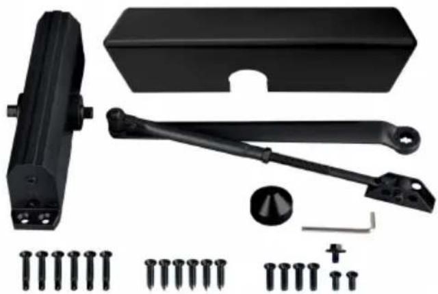
natural_image
Collection of black mechanical components including a sliding contactor, bracket, and screws (no text or symbols visible)STANDARD CLOSING CYCLE
OPENING DOOR CONTROL
CAUTION
DO NOT BACK VALVES OUT OF
CLOSER OR A LEAK WILL RESULT
ATTENTION:
BACKCHECK ("BC") VALVE
CONTROLS THE HYDRAULIC
RESISTANCE TO DOOR OPENING
IN BACKCHECK RANGE. NEVER
CLOSE THIS VALVE COMPLETELY.
IT IS NOT TO PROVIDE A POSITIVE STOP.

flowchart
graph TD
    A["OPENING"] --> B["CLOSED"]
    B --> C["BACKCHECK"]
    style A fill:#f9f,stroke:#333
    style C fill:#bbf,stroke:#333
TURN SPEED REGULATING VALVE CLOCKWISE TO SLOW DOWN OR COUNTER CLOCKWISE TO SPEED UP DOOR MOVEMENT

THIS VAVLE CONTROLS LATCHING SPEED
THIS VAVLE CONTROLS DOOR SWEEP SPEED
REGULATING SPRING POWER REGULATING BC POWER
POWER ADJUSTMENT SCREW. TURN THIS SCREW CLOCKWISE TO INCREASE OR COUNTER CLOCKWISE TO DECREASE.

TURN BC REGULATING VALVE CLOCKWISE TO INCREASE OR COUNTER CLOCKWISE TO DECREASE. NEVER CLOSE THIS VALVE COMPLETELY.
ADJUSTING FOOT FOR CLOSING POWER
MOVE FOOT PIVOT TO HOLE AS ILLUSTRATED BELOW

• RIGHT HAND DOOR ILLUSTRATED SAME DIMENSIONS APPLY TO LEFT HAND DOOR
• MEASURED FROM HINGE € DIMENSIONS ARE IN inches (mm)
• DO NOT SCALE DRAWING
* Door/Wall/Hardware/Jamb conditions permitting

natural_image
Technical line drawing of a mechanical lever system with a cylindrical component attached (no text or symbols)* Door/Wall/Hardware/Jamb conditions permitting
• RIGHT HAND DOOR ILLUSTRATED SAME DIMENSIONS APPLY TO LEFT HAND DOOR
• MEASURED FROM HINGE € DIMENSIONS ARE IN inches (mm)
• DO NOT SCALE DRAWING
natural_image
Technical line drawing of a mechanical assembly with no visible text or symbolsAbout Power Adjustment
Before installation, Adjust the spring power as chart in page 2. Adjust spring power DO NOT exceed the maximum turn.
The spring power has been reset on 0 turns in factory.
• RIGHT HAND DOOR ILLUSTRATED
SAME DIMENSIONS APPLY TO LEFT HAND DOOR
• MEASURED FROM HINGE ♦
DIMENSIONS ARE IN inches (mm)
• DO NOT SCALE DRAWING
| DIMENSIONS "A" | DIMENSIONS "B" | OPENING | ||
| inches | mm | inches | mm | |
| 9-1/4 | 235 | 7-5/8 | 194 | TO 100° |
| 7-3/4 | 197 | 6-1/8 | 156 | 101° TO 150° |
| 5-3/4 | 146 | 4-1/8 | 105 | OVER 151° |


Unit 5 Albert Edward House,
The Pavilions Preston, United Kingdom
pooledas123@gmail.com
01772418127
| EC | REP |
SHUNSHUN GmbH
Römeräcker 9 Z2021,76351
www.vevor.com/support
We continue to be committed to provide you tools with competitive price. "Save Half", "Half Price" or any other similar expressions used by us only represent estimate of savings you might benefit from buying certain tools with us compared top brands and does not necessarily mean to cover all categories of tools offered are kindly reminded to verify carefully when you are placing an order with us actually saving half in comparison with the top major brands.
VEVOR®
TOUGH TOOLS, HALF PRICE
DOOR CLOSER
MODEL : D4015 / D4016

natural_image
Metallic hand-operated door lock device with adjustable lever and base (no text or symbols visible)NEED HELP? CONTACT US!
Have product questions? Need technical support? Please feel fr contact us:
Technical Support and E-Warranty Certificate www.vevor.com/support
This is the original instruction, please read all manual instruction carefully before operating. VEVOR reserves a clear interpretation user manual. The appearance of the product shall be subject to product you received. Please forgive us that we won't inform you there are any technology or software updates on our product.
WAARSCHUWING:
natural_image
Collection of industrial mechanical components including a sliding door, bracket, and tools (no text or symbols visible)
natural_image
Collection of black mechanical components including a lock, handle, screwdriver, and bolts (no text or symbols visible)| NEE | AFBEELDING | DEELNAAM | AANT AL |
| A | | Deurdranger lichaam | 1 |
| B | | HO-arm | 1 |
| C | | Tuimelaarbout M6×10 | 1 |
| D | | Houten Deuren Schroef ST6,3×3 | 6 |
| E | | Inbussleutel | 1 |
| F | [CDWZ] | Zelftappende schroef ST6,3×38 | 6 |
| G |  | Metalen deuren Schroef 1/4-20×1 | 2 |
| H |  | Metalen deuren Schroef 1/4-20×2 | 4 |
| I | | Rondsel kap | 1 |
| J | Plastic hoesje | 1 |
PRODUCT PAREMETERS
STANDARD CLOSING CYCLE
OPENING DOOR CONTROL
CAUTION
DO NOT BACK VALVES OUT OF
CLOSER OR A LEAK WILL RESULT
ATTENTION:
BACKCHECK ("BC") VALVE
CONTROLS THE HYDRAULIC
RESISTANCE TO DOOR OPENING
IN BACKCHECK RANGE. NEVER
CLOSE THIS VALVE COMPLETELY.
IT IS NOT TO PROVIDE A POSITIVE STOP.
flowchart
graph TD
    A["OPENING"] --> B["CLOSED"]
    B --> C["BACKCHECK"]
    C --> D["STOP"]
    style A fill:#f9f,stroke:#333
    style B fill:#ccf,stroke:#333
    style C fill:#cfc,stroke:#333
    style D fill:#fcc,stroke:#333
TURN SPEED REGULATING VALVE CLOCKWISE TO SLOW DOWN OR COUNTER CLOCKWISE TO SPEED UP DOOR MOVEMENT

THIS VAVLE CONTROLS LATCHING SPEED
THIS VAVLE CONTROLS DOOR SWEEP SPEED
REGULATING SPRING POWER REGULATING BC POWER
POWER ADJUSTMENT SCREW. TURN THIS SCREW CLOCKWISE TO INCREASE OR COUNTER CLOCKWISE TO DECREASE.

TURN BC REGULATING VALVE CLOCKWISE TO INCREASE OR COUNTER CLOCKWISE TO DECREASE. NEVER CLOSE THIS VALVE COMPLETELY.
ADJUSTING FOOT FOR CLOSING POWER
MOVE FOOT PIVOT TO HOLE AS ILLUSTRATED BELOW

5. Normale arminstallatie.

| DIMENSIONS "A" | OPENING | |
| inches | mm | |
| 7 | 178 | T100° |
| 6 | 152 | 101°T0120° |
| 3-1/2 | 89 | *121°T0180° |
• RIGHT HAND DOOR ILLUSTRATED SAME DIMENSIONS APPLY TO LEFT HAND DOOR
• MEASURED FROM HINGE € DIMENSIONS ARE IN inches (mm)
• DO NOT SCALE DRAWING
* Door/Wall/Hardware/Jamb conditions permitting

natural_image
Technical line drawing of a mechanical device with a cylindrical component attached to a rod (no text or symbols)• RIGHT HAND DOOR ILLUSTRATED
SAME DIMENSIONS APPLY TO LEFT HAND DOOR
• MEASURED FROM HINGE €
DIMENSIONS ARE IN inches (mm)
• DO NOT SCALE DRAWING
* Door/Wall/Hardware/Jamb conditions permitting
natural_image
Technical line drawing of a mechanical assembly with no visible text or symbolsAbout Power Adjustment
Before installation, Adjust the spring power as chart in page 2. Adjust spring power DO NOT exceed the maximum turn.
The spring power has been reset on 0 turns in factory.
• RIGHT HAND DOOR ILLUSTRATED
SAME DIMENSIONS APPLY TO LEFT HAND DOOR
• MEASURED FROM HINGE ♦
DIMENSIONS ARE IN inches (mm)
• DO NOT SCALE DRAWING
| DIMENSIONS "A" | DIMENSIONS "B" | OPENING | ||
| inches | mm | inches | mm | |
| 9-1/4 | 235 | 7-5/8 | 194 | TO 100° |
| 7-3/4 | 197 | 6-1/8 | 156 | 101° TO 150° |
| 5-3/4 | 146 | 4-1/8 | 105 | OVER 151° |


Unit 5 Albert Edward House,
The Pavilions Preston, United Kingdom
pooledas123@gmail.com
01772418127
| EC | REP |
SHUNSHUN GmbH
Römeräcker 9 Z2021,76351
www.vevor.com/support
Gemaakt in China
VEVOR®
TOUGH TOOLS, HALF PRICE
We continue to be committed to provide you tools with competitive price. "Save Half", "Half Price" or any other similar expressions used by us only represent estimate of savings you might benefit from buying certain tools with us compared top brands and does not necessarily mean to cover all categories of tools offered are kindly reminded to verify carefully when you are placing an order with us actually saving half in comparison with the top major brands.
VEVOR®
TOUGH TOOLS, HALF PRICE
DOOR CLOSER
MODELL : D4015 / D4016
natural_image
Metallic hand-operated door lock device with adjustable lever and base (no text or symbols visible)NEED HELP? CONTACT US!
Have product questions? Need technical support? Please feel fr contact us:
Technical Support and E-Warranty Certificate www.vevor.com/support
This is the original instruction, please read all manual instruction carefully before operating. VEVOR reserves a clear interpretation user manual. The appearance of the product shall be subject to product you received. Please forgive us that we won't inform you there are any technology or software updates on our product.
WARNING:
natural_image
Collection of industrial mechanical components including a sliding door, bracket, and tools (no text or symbols visible)
natural_image
Collection of black automotive components including a lock, handle, screwdriver, and bolts (no text or symbols visible)STANDARD CLOSING CYCLE
OPENING DOOR CONTROL
CAUTION
DO NOT BACK VALVES OUT OF
CLOSER OR A LEAK WILL RESULT
ATTENTION:
BACKCHECK ("BC") VALVE
CONTROLS THE HYDRAULIC
RESISTANCE TO DOOR OPENING
IN BACKCHECK RANGE. NEVER
CLOSE THIS VALVE COMPLETELY.
IT IS NOT TO PROVIDE A POSITIVE STOP.

flowchart
graph TD
    A["OPENING"] --> B["CLOSED"]
    B --> C["BACKCHECK"]
    C --> D["STOP"]
    style A fill:#f9f,stroke:#333
    style B fill:#ccf,stroke:#333
    style C fill:#cfc,stroke:#333
    style D fill:#fcc,stroke:#333
TURN SPEED REGULATING VALVE CLOCKWISE TO SLOW DOWN OR COUNTER CLOCKWISE TO SPEED UP DOOR MOVEMENT

THIS VAVLE CONTROLS LATCHING SPEED
THIS VAVLE CONTROLS DOOR SWEEP SPEED
REGULATING SPRING POWER REGULATING BC POWER
POWER ADJUSTMENT SCREW. TURN THIS SCREW CLOCKWISE TO INCREASE OR COUNTER CLOCKWISE TO DECREASE.
TURN BC REGULATING VALVE CLOCKWISE TO INCREASE OR COUNTER CLOCKWISE TO DECREASE. NEVER CLOSE THIS VALVE COMPLETELY.
ADJUSTING FOOT FOR CLOSING POWER
MOVE FOOT PIVOT TO HOLE AS ILLUSTRATED BELOW

5. Vanlig arminstallation.
| DIMENSIONS "A" | OPENING | |
| inches | mm | |
| 7 | 178 | T100° |
| 6 | 152 | 101°T0120° |
| 3-1/2 | 89 | *121°T0180° |
• RIGHT HAND DOOR ILLUSTRATED SAME DIMENSIONS APPLY TO LEFT HAND DOOR
• MEASURED FROM HINGE € DIMENSIONS ARE IN inches (mm)
• DO NOT SCALE DRAWING
* Door/Wall/Hardware/Jamb conditions permitting

installations instruktioner
natural_image
Technical line drawing of a mechanical lifting device with a cylindrical component attached (no text or symbols)• RIGHT HAND DOOR ILLUSTRATED
SAME DIMENSIONS APPLY TO LEFT HAND DOOR
• MEASURED FROM HINGE ♦
DIMENSIONS ARE IN inches (mm)
• DO NOT SCALE DRAWING
* Door/Wall/Hardware/Jamb conditions permitting
natural_image
Technical line drawing of a mechanical assembly with no visible text or symbolsAbout Power Adjustment
Before installation, Adjust the spring power as chart in page 2. Adjust spring power DO NOT exceed the maximum turn.
The spring power has been reset on 0 turns in factory.
Unit 5 Albert Edward House,
The Pavilions Preston, United Kingdom
pooledas123@gmail.com
01772418127
| EC | REP |
SHUNSHUN GmbH
Römeräcker 9 Z2021,76351