
BY433E - Personal protective equipment Vevor - Free user manual and instructions
Find the device manual for free BY433E Vevor in PDF.
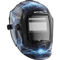


| Product Type | Auto-Darkening Welding Helmet |
| Brand | Vevor |
| Model | BY433E |
| ADF Cartridge Size | 110 x 90 mm (4.33 x 3.54 inches) |
| LCD Display Area | 93 x 43 mm (3.66 x 1.69 inches) |
| UV/IR Protection | Yes |
| Number of Arc Sensors | 2 |
| Variable Shades (Dark) | Shade 9 to 13 |
| Fixed Shade (Light) | Shade 4 |
| Shade Control | Variable adjustment via external knob |
| Sensitivity Control | Variable adjustment via external knob |
| Delay Control (Dark → Light) | 0.1 to 1.0 second |
| Power Supply | Solar cells + 2 CR2032 lithium batteries |
| Switching Time (Light → Dark) | 1/25,000 s |
| Operating Temperature | -5°C to 55°C (23°F to 131°F) |
| Storage Temperature | -20°C to 70°C (-4°F to 158°F) |
| Safety Standards | ANSI Z49.1, ANSI Z87.1 |
| Maintenance | Clean with soapy water solution and soft cloth; replace scratched protective lenses |
| Main Spare Parts | Front Lens (BY-010003), ADF (BY-010001), Inner Lens (BY-010005), Cartridge Holder (BY-010018), Shell (BY-010002) |
| Repairability | Battery, ADF cartridge and protective lenses user-replaceable |
| Manufacturer | Shanghai Muxinmuyeyouxiangongsi, China |
Frequently Asked Questions - BY433E Vevor
User questions about BY433E Vevor
0 question about this device. Answer the ones you know or ask your own.
Ask a new question about this device
Download the instructions for your Personal protective equipment in PDF format for free! Find your manual BY433E - Vevor and take your electronic device back in hand. On this page are published all the documents necessary for the use of your device. BY433E by Vevor.
USER MANUAL BY433E Vevor
Affordable. Reliable. Home Improvement.
WELDING HELMET
MODEL:BY433E
VEVOR
Affordable. Reliable. Home Improvement.
WELDING HELMET
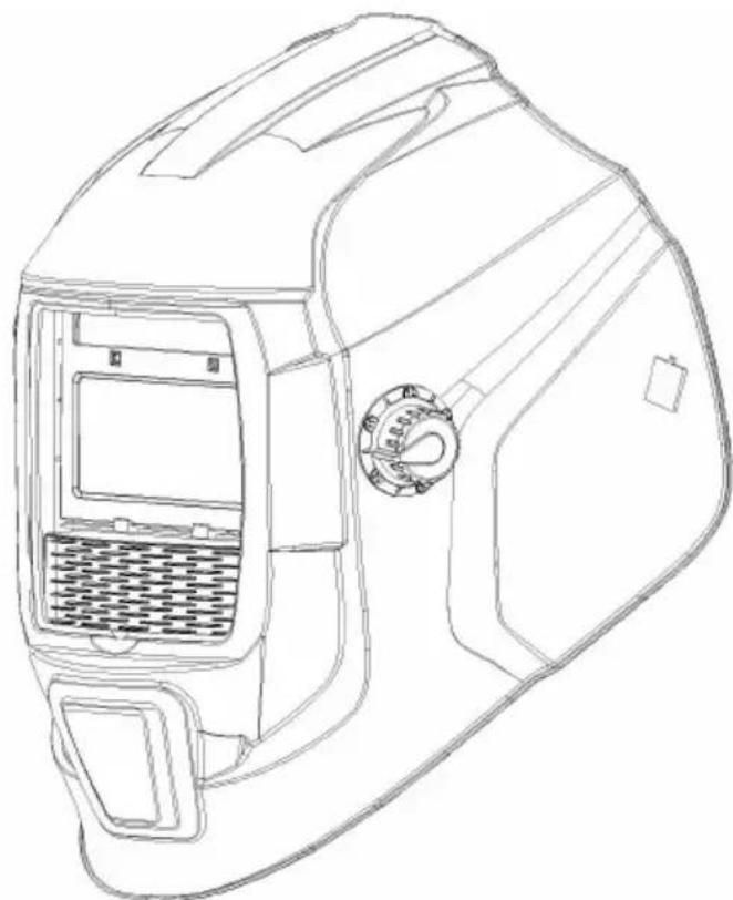
This is the original instruction. Please read all manual instructions carefully before operating. VEVOR reserves a clear interpretation of our user manual. The appearance of the product shall be subject to the product received. Please forgive us that we won't inform you again if there are technology or software updates on our product.

Warning: To reduce the risk of injury, user must read instruction manual carefully.
SAFETY INSTRUCTIONS
WARNING:
Read this material before using this product. Failure to do so can result in injury.
WELDING HELMET SAFETY PRECAUTIONS
READ BEFORE USING
Protect yourself and others from injury — read, follow, and save these important safety precautions and operating instructions.
Symbol Usage
DANGER! - Indicates a hazardous situation which, if not avoided, will result in death or serious injury. The possible hazards are shown in the adjoining symbols or explained in the text.
Indicates a hazardous situation which, if not avoided, could result in death or serious injury. The possible hazards are shown in the adjoining symbols or explained in the text.
NOTICE - Indicates statements not related to personal injury.
Indicates special instructions.

This group of symbols means Warning!
Watch Out! ELECTRIC SHOCK, MOVING PARTS, and HOT PARTS hazards.
Consult symbols and related instructions below for necessary actions to avoid hazards.
Arc Welding Hazards

Only qualified persons should install, operate, maintain, and repair the unit.
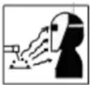
ARC RAYS can burn eyes and skin.
Arc rays from the welding process produce intense visible and invisible (ultraviolet and infrared) rays that can burn eyes and skin. Sparks from the weld.
- Wear a welding helmet fitted with a proper shade of filter to protect your face and eyes when welding or watching (see ANSI Z49.1 and Z87.1 listed in Safety Standards). Refer to Shade and sensitivity charts. Wear approved safety glasses with side shields under your helmet.
- Use protective screens or barriers to protect others from flash, glare, and sparks; warn others not to watch the arc.
- Wear body protection made from durable, flame-resistant material (leather, heavy cotton, wool). Body protection includes oil-free clothing such as leather gloves, heavy shirt, cuffless trousers, high shoes, and a cap.
- Before welding, adjust the auto-darkening lens sensitivity setting to meet the application.
- Stop welding immediately if the auto-darkening lens does not darken when the arc is struck. See the Owner's Manual for more information.
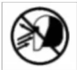
WELDING HELMETS do not provide unlimited eye, ear, and face protection.
Arc rays from the welding process produce intense visible and invisible (ultraviolet and infrared) rays that can burn eyes and skin. Sparks fly off from the weld.
- Use impact resistant safety spectacles or goggles and ear protection at all times when using this welding helmet.
- Do not use this helmet while working with or around explosives or corrosive liquids.
- Do not weld in the overhead position while using this helmet.
- Inspect the auto-lens frequently. Immediately replace any scratched, cracked, or pitted cover lenses or auto-lenses.
- NOISE can damage hearing.
- Noise from some processes or equipment can damage hearing.
- Wear approved ear protection if noise level is high.
READ INSTRUCTIONS.
Read and follow all labels and the Owner's Manual carefully before installing, operating, or servicing unit. Read the safety information at the beginning of the manual and in each section.
- Use only genuine replacement parts from the manufacturer.
- Perform maintenance and service according to the Owner's Manuals, industry standards, and national, state, and local codes.
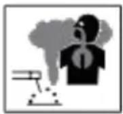
FUMES AND GASES can be hazardous.
Welding produces fumes and gases. Breathing these fumes and gases can be hazardous to your health.
- Keep your head out of the fumes. Do not breathe the fumes.
- If inside, ventilate the area and/or use local forced ventilation at the arc to remove welding fumes and gases. The recommended way to determine adequate ventilation is to sample for the composition and quantity of fumes and gases to which personnel are exposed.
- If ventilation is poor, wear an approved air-supplied respirator.
- Read and understand the Safety Data Sheets (SDSs) and the manufacturer instructions for adhesives, coatings, cleaners, consumables, coolants, degreasers, fluxes, and metals.
- Work in a confined space only if it is well ventilated, or while wearing an air-supplied respirator. Always have a trained watch person nearby. Welding fumes and gases can displace air and lower the oxygen level causing injury or death. Be sure the breathing air is safe.
- Do not weld in locations near degreasing, cleaning, or spraying operations. The heat and rays of the arc can react with vapors to form highly toxic irritating gases.
- Do not weld on coated metals, such as galvanized, lead, or cadmium plate steel, unless the coating is removed from the weld area, the area is well ventilated, and while wearing an air-supplied respirator. The coatings and any metals containing these elements can give off toxic fumes if welded.
Proposition 65 Warnings
Welding or cutting equipment produces fumes or gases which contain chemicals known to the State of California to cause birth defects and, in some cases, cancer. (California Health & Safety Code Section 25249.5
seq.)
SPECIFICATIONS
| Optical Class | 1/1/1/2 |
| LCD viewing Area | 93 x 43 mm (3.66 x 1.69 in.) |
| Cartridge size | 110 x 90mm (4.33 x 3.54in.) |
| UV/IR protection | UV/IR protection |
| Arc senso | 2 |
| variable welding shades | WELD ModelDarkened State:NO.9-13/LightState:NO.4 |
| shade Control | variable adjust by external knob |
| sensitivity Control | variable adjust by external knob |
| power supply | solar cells with battery assist |
| Battery | CR203 Lithium (2 Required) |
| Power On/Off | Fully automatic |
| Light to Dark switching Time | 1/25,000sec. |
| Dark to Light switching Time | 0.1sec.-1.0 sec. |
| TIG Rating | DC≥ 15 amps; AC≥ 15 amps |
| Operating Temperature | 23°F ~ 13°F (-5°C ~ 5°C) |
| storage Temperature | -4°F~ 158°F (-20°C ~ 70°C) |
OPERATING INSTRUCTIONS
Helmet Controls
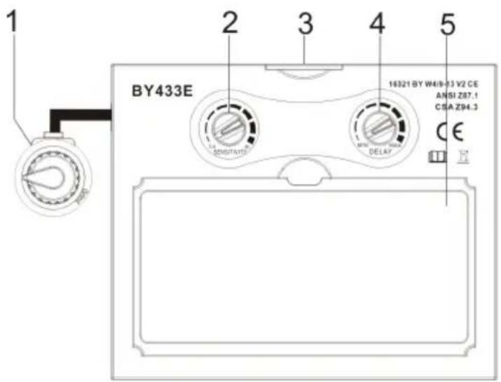
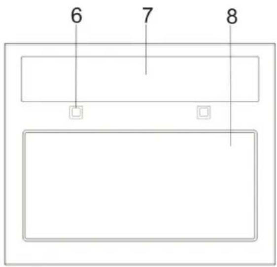
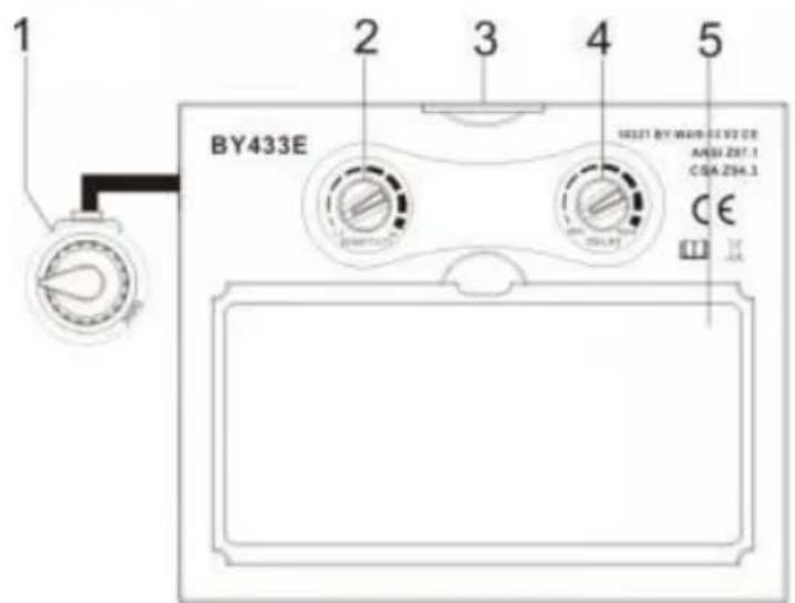
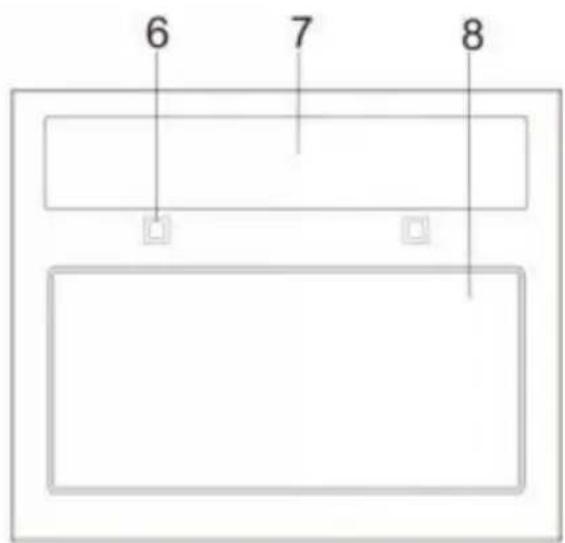
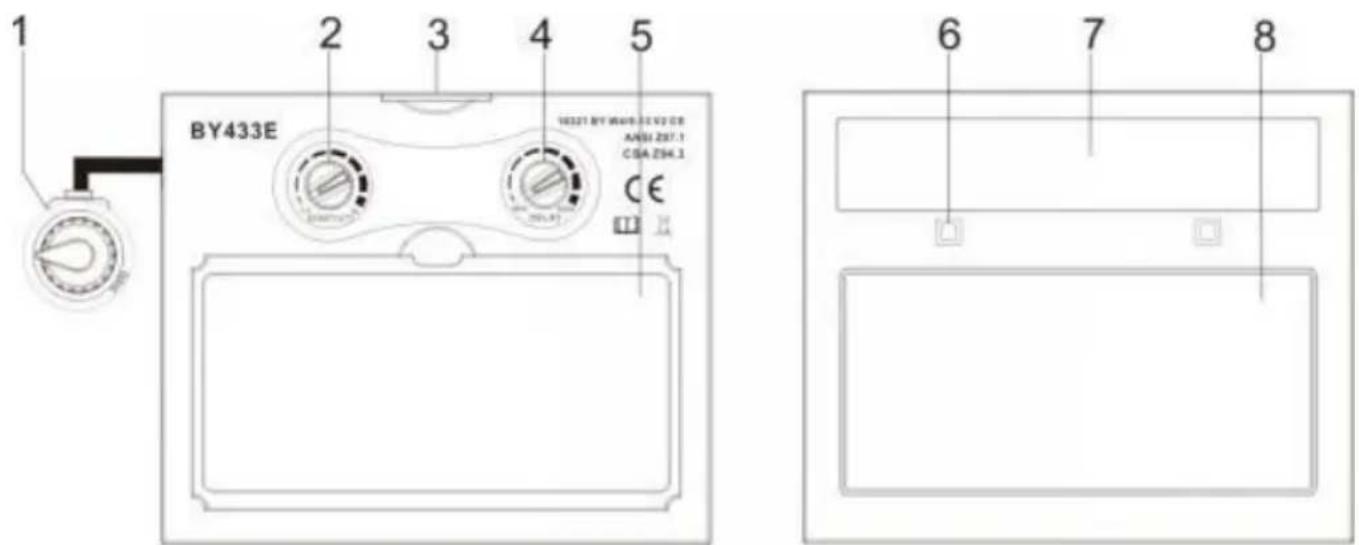
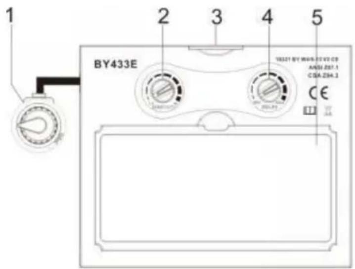
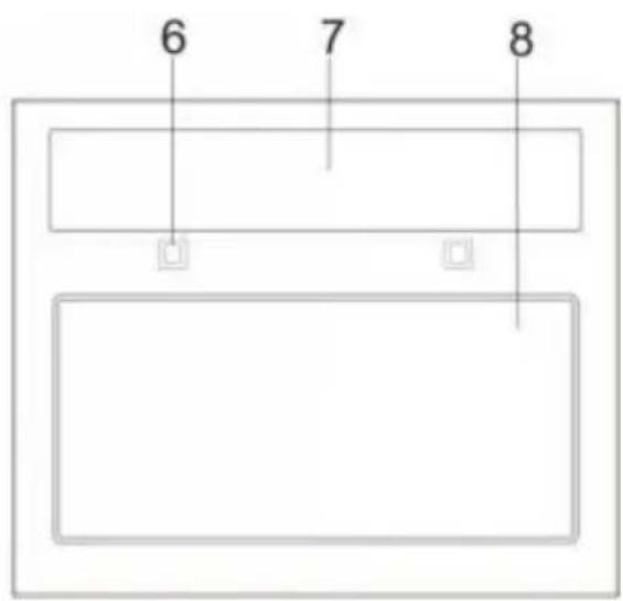
| NO. | DESCRIPTLON |
| 1 | Shade control knob |
| 2 | Low voltage indicator |
| 3 | Self-test button |
| 4 | Sensitivity control knob |
| 5 | Lithium battery |
| 6 | Delay time control knob |
| 7 | LCD |
| 8 | CUT-Weld |
| 9 | Arc censor |
| 10 | Solar cell |
| 11 | UV/IR filter |
OPERATING INSTRUCTIONS
Lens Delay Control
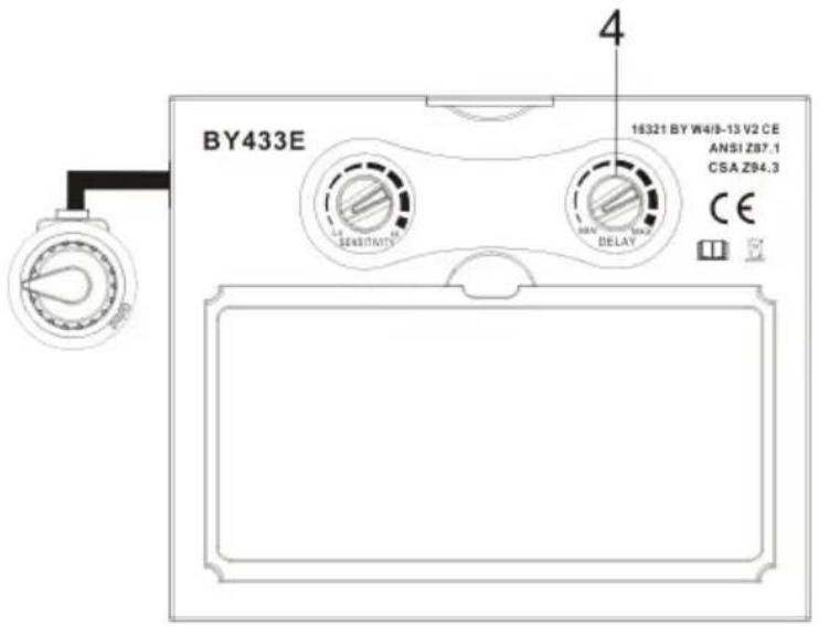
from min (0.10 second) to max (1.0 second).
1 Lens Delay Control
The lens delay control is used to adjust the time for the lens to switch to the clear state after welding.
The delay is particularly useful in eliminating bright after-rays present in higher amperage applications where the molten puddle remains bright momentarily after welding. Lens delay adjusts
Sensitivity Control
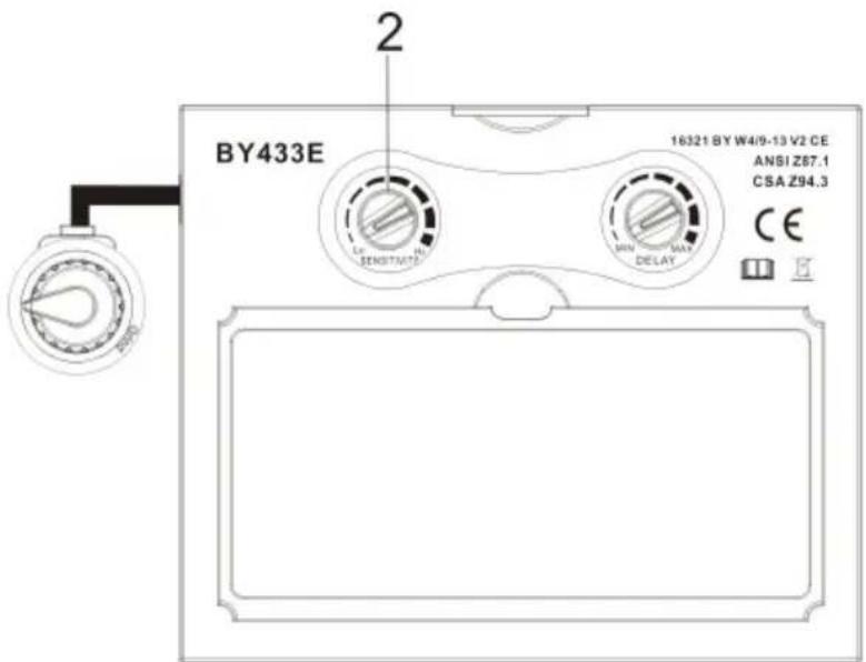
Press button “SENSITIVITY” it is selected according to welding process and environmental light, the defaulted sensitivity is medium.
- Select minimum: Suitable for high amperage welding or welding in bright environmental light (For example, there is
disturbing light from other welder vicinity)
- Select maximum: Suitable for low amperage welding, using in poor light conditions (For example, pipe welding where part of the arc is obscured from and where the welding arc becomes stable (For example, TIG welding).
Variable Shade Control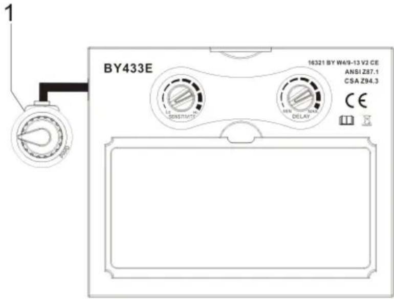
1 Variable Shade Control Use the control to adjust the lens shade in the darkened state. Use the table below to select proper shade control setting based on your welding process. The shade ranges for each mode are as follows: Weld: No. 9 - No. 13
Reference: ANSI Z49.1:2005
| Process | Electrode Size in. (mm) | Arc Current in Amperes | Minimum Protective Shade No. | Suggested Shade No. (Comfort)* |
| Shielded Metal Ar Welding (SMAW) | Less than 3/32(2.4) 3/32-5/32(2.4-4.0) 5/32-1/4(4.0-6.4) More than 1/4 (6.4) | Less than 660-160160-250250-550 | 781011 | --101214 |
| Gas Metal Arc Welding (GMAW) | Less than 660-160160-250250-500 | 7101010 | --111214 | |
| Flux Cored Arc Welding (FCAW) | ||||
| Gas Tungsten Ar Welding (TIG) | Less than 5050-150150-500 | 8810 | 101214 | |
| Air Carbon Arc Cutting (CAC-A) | Light Heavy | Less than 50500-1000 | 1011 | 1214 |
| Plasma ArcCutting (PAC) | Less than 20 | 4 | 4 | |
| 20-40 | 5 | 5 | ||
| 40-60 | 6 | 6 | ||
| 60-80 | 8 | 8 | ||
| 80-300 | 8 | 9 | ||
| 300-400 | 9 | 12 | ||
| 400-800 | 10 | 14 | ||
| Plasma ArcWelding(PAW) | Less than 20 | 6 | ||
| 20-100 | 8 | 6-8 10 12 | ||
| 100-400 | 10 | 14 | ||
| 400-800 | 11 |
* Start with a shade that is too dark to see the weld zone. Then, go to a which gives a sufficient view of the weld zone without going below the minimum.
ADJUSTING HEADGEAR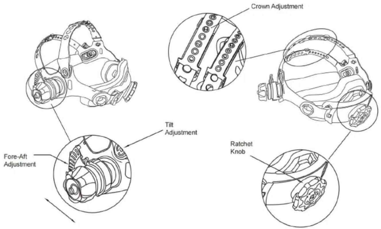
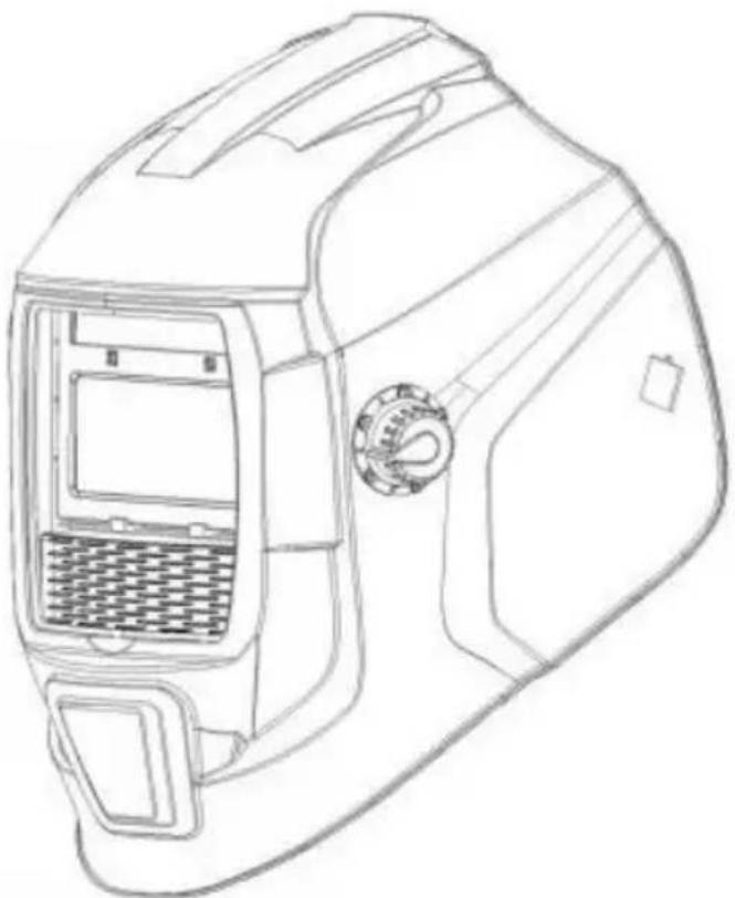
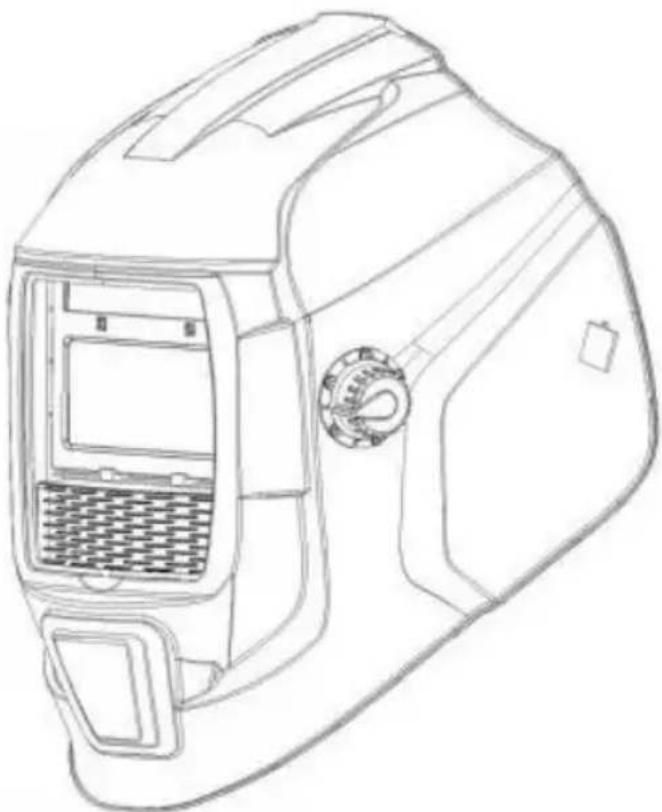
HEAD SIZE ADJUSTMENT: HEADGEAR TIGHTNESS is adjusted by turning the Ratchet Knob to the right or left to adjust for the desired head size. This is located at the back of the helmet.
ADJUSTMENT is made by adjusting the comfort then placing the strap under guide and snapping the pins into the holes to lock securely in place.
TILT: Tilt adjustment is located on the right side of the helmet. Loosen the headgear tension knob and push the top end of the adjustment lever outward until the lever's Stop Tab clears the notches. Then rotate the lever forward or backward to the desired tilt position. The Stop will automatically engage again when released, locking the helmet into position.
FORE / AFT ADJUSTMENT: Adjusts the distance between the user's face and lens. To adjust, slide and hold the spring loaded caps upward while moving headgear into one of four slotted locations. Once the desired distance has been achieved, let go of the cap and it will return to its resting position once the headgear is secured in one of the four slots.
NOTE: Make sure both sides are equally positioned for proper orientation.
REPLACING THE BATTERY
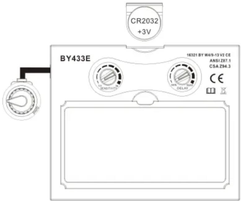
This ADF is powered by a replaceable battery and solar power. The battery is located at the bottom corner of the ADF cartridge. Replace the battery when the LOW BATTERY light is lit. Replace with CR2032 lithium type batteries (2 required) or equivalent. Be sure Positive (+) side of the
battery faces up (toward inside of helmet).
CARTRIDGE AND LENS REPLACEMENT
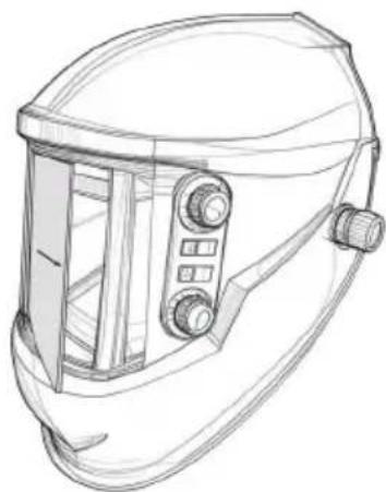
Warning: Never use the auto-darkening lens without the inside and outside lens covers properly installed. Welding spatter will damage the auto-darkening lens and void the warranty.
Front clear cover Lens:
Remove the outside cover lens by prying from groove and reinstall a new one.
Replacing inside clear Lens
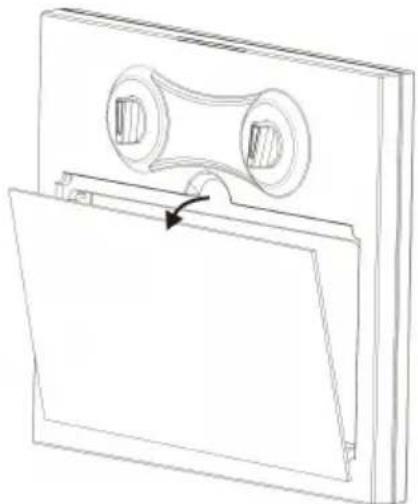
Warning: There is a cable connecting the battery and the lens. Please be careful not to break it.
Inside Lens Cover
Remove the inside lens cover by prying the cover from the groove in the gasket and reinstall a new one.
CARTRIDGE AND LENS REPLACEMENT
Change the Shade cartridge
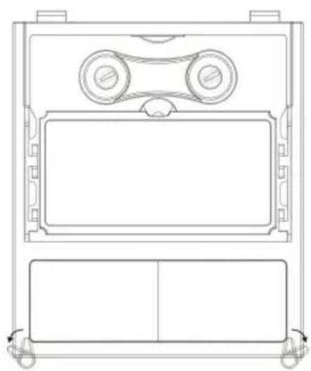
Figure 1
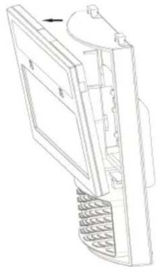
Figure 2
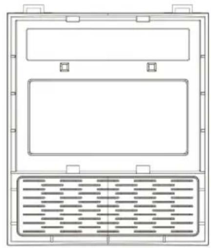
Figure 3
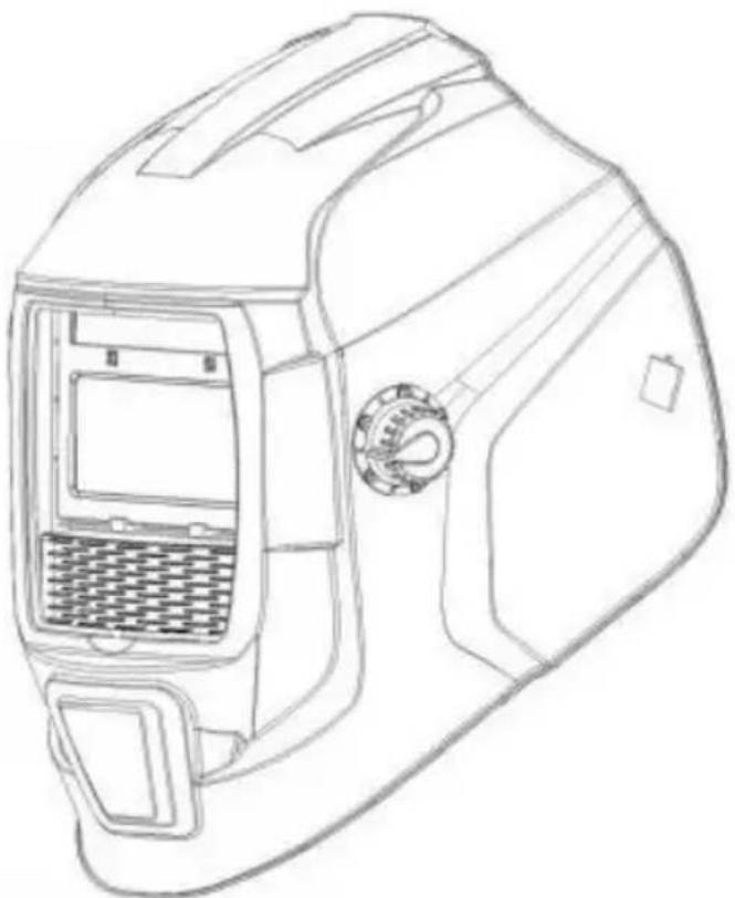
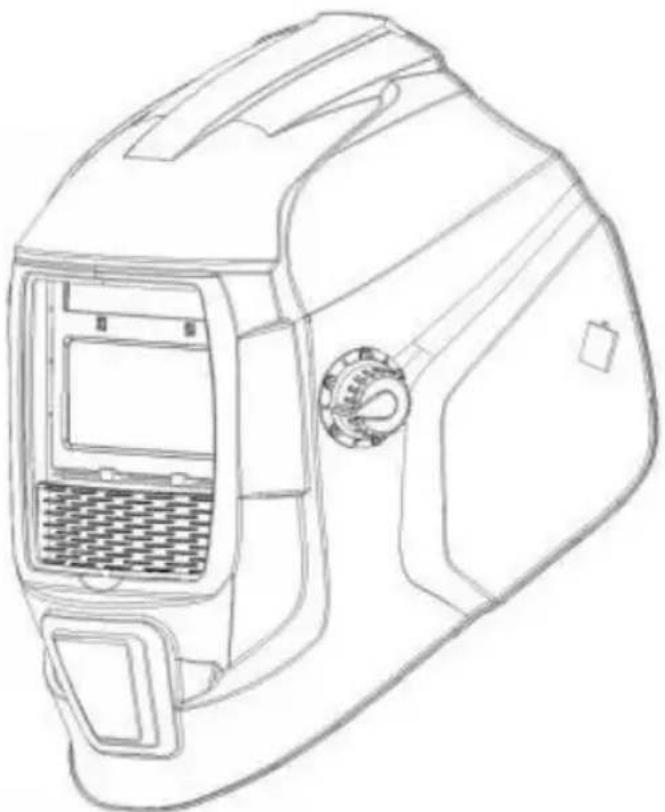
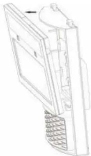
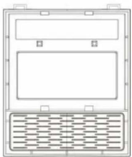
Remove the ADF holder assembly from the helmet shell. See Figure 1 and Figure 2 for removal. Flex the bottom end of the ADF holder to allow the ADF cartridge to be removed from the frame. Install the new ADF cartridge into the frame per Figure 3 below, making sure that the ADF cartridge is inserted in the ADF holder correctly as shown. Include the ADF holder assembly into the helmet shell.
Installing an Aftermarket Magnifying Lens
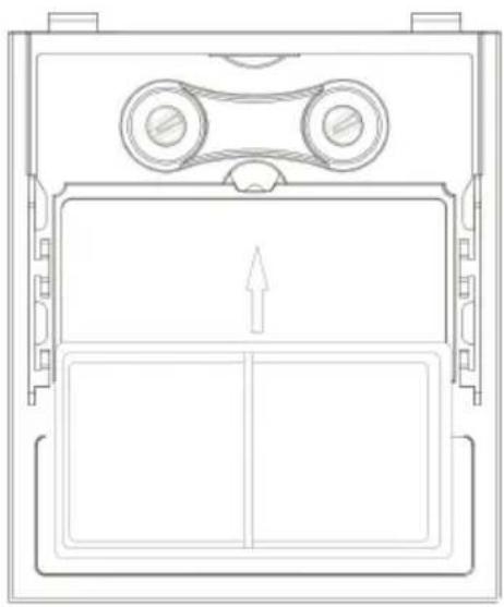
Figure 4
Simply slide the magnifying lens into the short rail located on the sides of the ADF holder per Figure 4. The shade cartridge must be removed from the ADF holder to install the magnifying lens.
COMMON PROBLEMS AND REMINDERS
| PROBLEM | POSSIBLE CAUSE | SOLUTION |
| Difficult to see through filter. | Front cover lens dirty. | Clean or replace front cover le |
| Cartridge dirty. | Clean the Auto-Darkening cartridge with soapy water solution and soft cloth. | |
| Filter does no darken when arc is struck. | sensitivity is set too lo | Adjust sensitivity to required lev |
| Front cover lens dirty. | Clean or replace front cover le | |
| Front cover lens is damaged. | Check for cracked or pitted fro cover lens and replace as required. | |
| sensors are blocked or solar panel is blocked. | Make sure you are not blocking the sensors or solar panels with your arm or other obstacle while welding. Adjust your position so that the sensors can see the we arc. | |
| Grind Mode selected. | Make sure proper shade is selected. | |
| Is the switch on 5-9/9-13 stuck in the middle. | Turn the switch to the correct position. | |
| Filter remains | sensitivity set too high | Adjust sensitivity to required lev |
| dark after completing a weld. | Delay time set too high | Adjust delay time to required level. |
| Low Battery. | Replacing battery. | |
| Filter does not darken when TEST button is pushed. | Low battery. | Replacing battery. |
| the LED will not turn on after pressing button. | Plug-in jack from filter not completely inserted | Remove plug-in jack port and re-insert it into the port. |
WARNING! Operator must stop using the auto-darkening filter welding helmet immediately if the above-mentioned problems cannot be corrected. Contact the dealer.
CORRECT DISPOSAL
This product is subject to the provisions of European Directive 2012/19/EU. The symbol showing a wheelie bin crossed through indicates that the product requires separate refuse collection in the European Union. This applies to the product and all accessories marked
with this symbol. Products marked as such may not be discarded with normal domestic waste, but must be taken to a collection point for recycling electrical and electronic devices.
REPLACEMENT PARTS
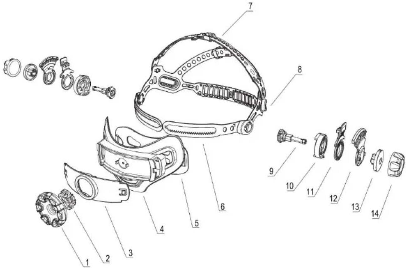
| NO. | DESCRIPTLON | NO. | DESCRIPTLON |
| 1 | Hand wheel gear | 8 | Fastener |
| 2 | Pinion | 9 | Retainer |
| 3 | Back cover1 | 10 | Position-hold button-1 |
| 4 | Back cover2 | 11 | Position-hold plate |
| 5 | Gear bar | 12 | Position-hold button-2 |
| 6 | Scallops1 | 13 | Nut |
| 7 | Scallops2 | 14 |
REPLACEMENT PARTS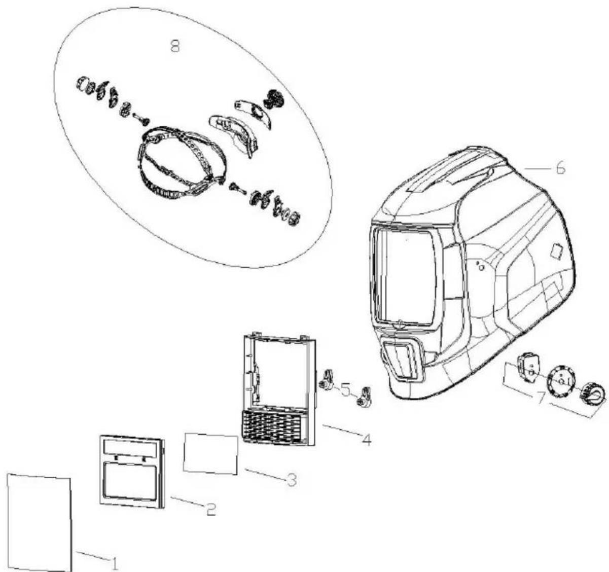
| NO. | PART NO. | DESCRIPTLON | QTY |
| 1 | BY-010003 | Front Cover Lens | 1 |
| 2 | BY-010001 | ADF | 1 |
| 3 | BY-010005 | Inside Cover Lens | 1 |
| 4 | BY-010018 | Cartridge Holder | 1 |
| 5 | BY-010019 | Cartridge Holder Knob | 2 |
| 6 | BY-010002 | Helmet Shell | 1 |
| 7 | BY-010025 | Variable Shade Control | 1 |
| 8 | BY-010014 | Headgear | 1 |
Manufacturer: Shanghai Muxin Muye Youxian Gongsi
Address: Shuangcheng Lu 803 Nong 11 Hao 1602A-1609 Shi, Baoshan Qu, Shanghai 200000 CN.
Imported to AUS: SIHAO PTY LTD. 1 ROKEVA STREET, EASTWOOD NSW 2 Australia
Imported to USA: Sanven Technology Ltd. Suite 250, 9166 Anaheim Place, Rancho Cucamonga, CA 91730
| UK | REP |
YH CONSULTING LIMITED. C/O YH Consulting Limited Office 147, Centurion House, London Road, Staines-upon-Thames, Surrey, TW18 4A>
| EC | REP |
Affordable. Reliable. Home Improvement.
WELDING HELMET
MODEL: BY433E
VEVOR
Affordable. Reliable. Home Improvement.
WELDING HELMET
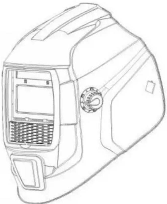
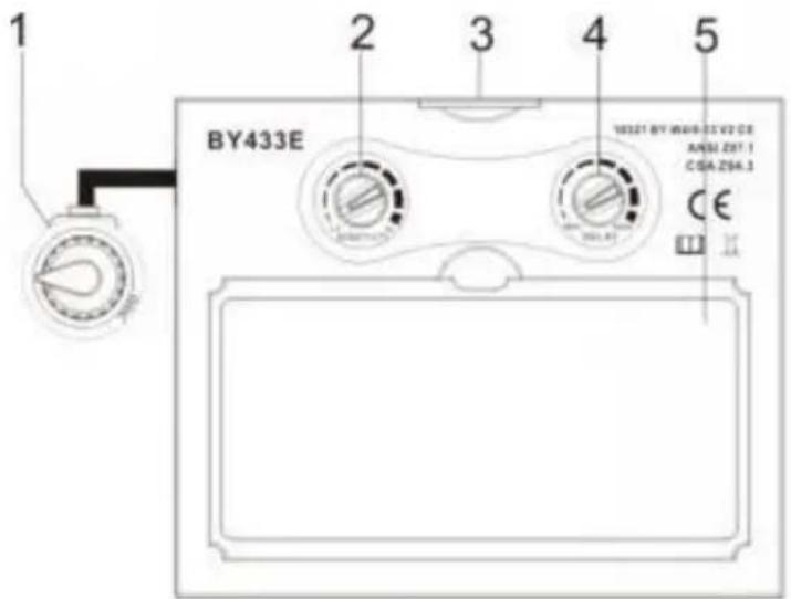
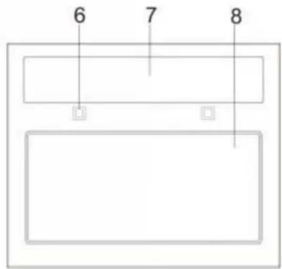
Figure 1
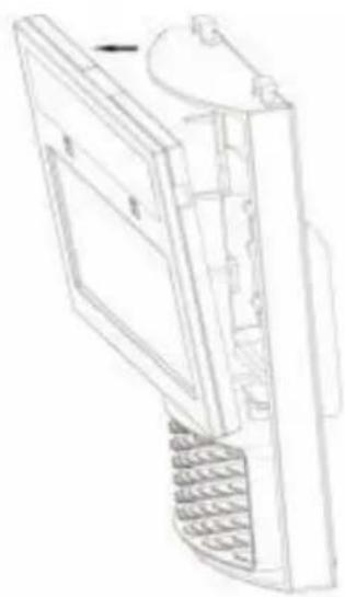
Figure 2
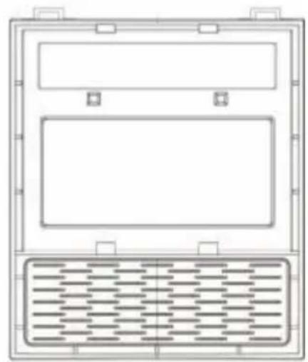
Figure 3
Figure 4
| NON . | DESCRIPTION | NON . | DESCRIPTION |
| 1 | Engrenage à volant | 8 | Attache |
| 2 | Pignon | 9 | Retenue |
| 3 | Dos couverture 1 | 10 | Position - maintenir bouton -1 |
| 4 | Dos couverture 2 | 11 | Plaque de maintien en position |
| 5 | Engrenage bar | 12 | Position - maintenir bouton -2 |
| 6 | CoquillesSaint-Jacques1 | 13 | Noix |
| 7 | CoquillesSaint-Jacques2 | 14 |
SPARE PARTS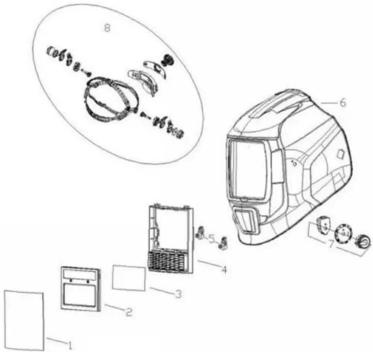
YH CONSULTING LIMITED. C/O YH Consulting Limited Office 147, Centurion House, London Road, Staines-upon-Thames, Surrey, TW18 4A>
| EC | REP |
Affordable. Reliable. Home Improvement.
WELDING HELMET
MODEL: BY433E
VEVOR
Affordable. Reliable. Home Improvement.
WELDING HELMET
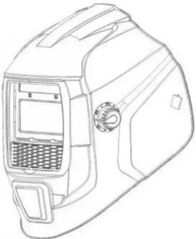

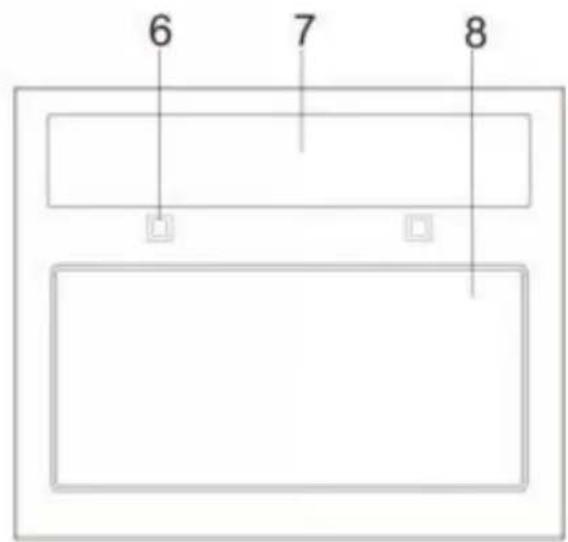
Figure 1
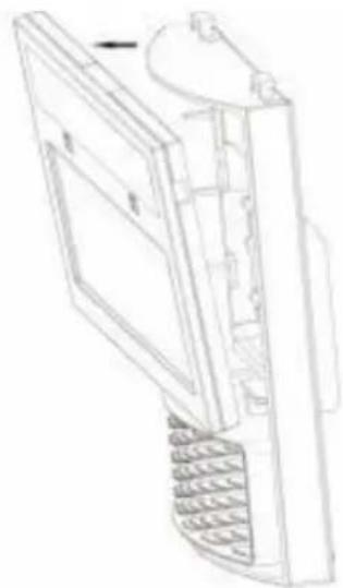
Figure 2
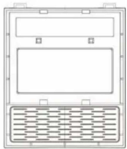
Figure 3
Figure 4
YH CONSULTING LIMITED. C/O YH Consulting Limited Office 147, Centurion House, London Road, Staines-upon-Thames, Surrey, TW18 4A>
| EC | REP |
WELDING HELMET
MODEL: BY433E
VEVOR
WELDING HELMET
HEAD SIZE ADJUSTMENT: THE HEADBAND
CARTRIDGE AND LENS REPLACEMENT
Figure 1
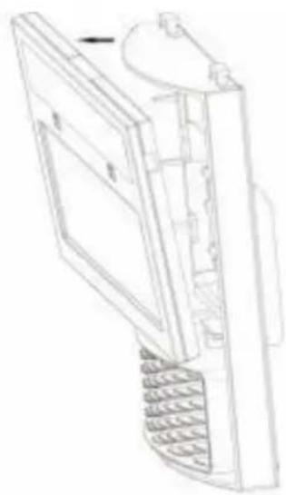
Figure 2
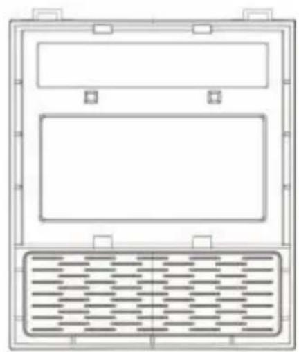
Figure 3
Figure 4
| NO. | PARTE NO. | DESCRIZIONE | QUANTITÀ |
| 1 | BY-010003 | Fronte Copertina Lente | 1 |
| 2 | BY-010001 | ADF | 1 |
| 3 | BY-010005 | Dentro Copertina Lente | 1 |
| 4 | BY-010018 | Cartuccia Titolare | 1 |
| 5 | BY-010019 | Cartuccia Pomello di supporto | 2 |
| 6 | BY-010002 | Casco Conchiglia | 1 |
| 7 | BY-01002 5 | Controllo variabile dell'ombra | 1 |
| 8 | BY-010014 | Copricapo | 1 |
Imported in AUS: SIHAO PTY LTD. 1 ROKEVA STREET EASTWOOD NSW 2122 Australia
Imported in USA: Sanven Technology Ltd. Suite 250, 9166 Anaheim Place Rancho Cucamonga, CA 91730
| UK | REP |
YH CONSULTING LIMITED. C/O YH Consulting Limited Office 147, Centurion House, London Road, Staines-upon-Thames, Surrey, TW18 4A>
| EC | REP |
WELDING HELMET
MODEL: BY433E
VEVOR
WELDING HELMET
CARTRIDGE AND LENS REPLACEMENT
Figure 1
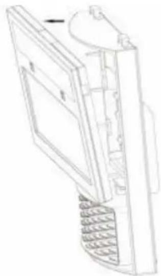
Figure 2
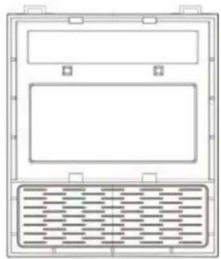
Figure 3
Figure 4
| NO. | PARTE NO. | DESCRIPCIÓN | CANTIDAD |
| 1 | BY-010003 | Frente Cubrir Lente | 1 |
| 2 | BY-010001 | ADF | 1 |
| 3 | BY-010005 | Adentro Cubrir Lente | 1 |
| 4 | BY-010018 | Cartucho Titular | 1 |
| 5 | BY-010019 | Cartucho Perilla de soporte | 2 |
| 6 | BY-010002 | Casco Caparazón | 1 |
| 7 | BY-01002 5 | Control de sombra variable | 1 |
| 8 | BY-010014 | Sombrero | 1 |
Manufacturer: Shanghaimuxinmuyeyouxiangongsi
Address: Shuangchenglu 803nong11hao1602A-1609shi, baoshanqu, shanghai 200000 CN.
Imported to AUS: SIHAO PTY LTD. 1 ROKEVA STREET, EASTWOOD, NSW 2122, Australia
Imported to USA: Sanven Technology Ltd. Suite 250, 9166 Anaheim Pla Rancho Cucamonga, CA 91730
| UK | REP |
YH CONSULTING LIMITED. C/O YH Consulting Limited Office 147, Centurion House, London Road, Staines-upon-Thames, Surrey, TW18 4A>
| EC | REP |
Affordable. Reliable. Home Improvement.
WELDING HELMET
MODEL: BY433E
VEVOR
Affordable. Reliable. Home Improvement.
WELDING HELMET
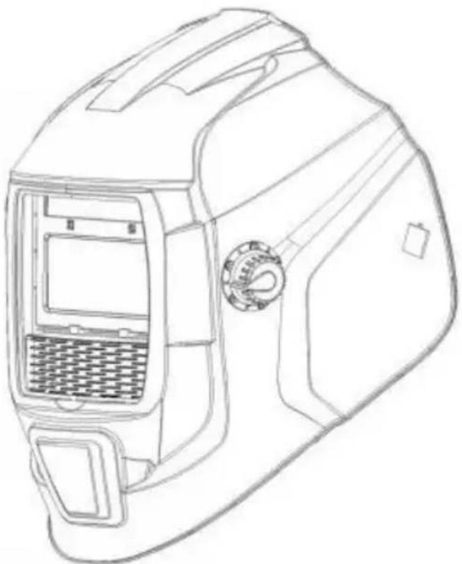

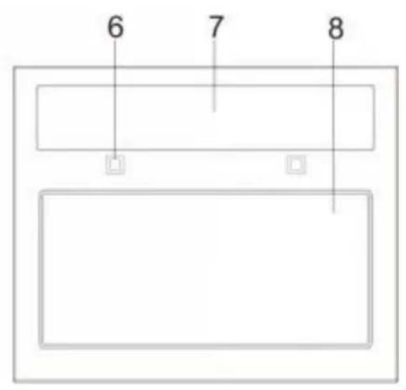
Figure 1
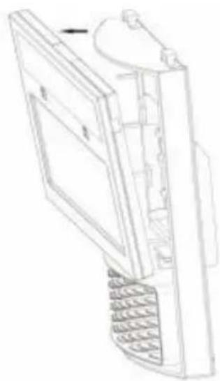
Figure 2
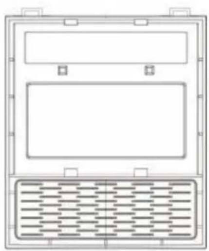
Figure 3
Figure 4
YH CONSULTING LIMITED. C/O YH Consulting Limited Office 147, Centurion House, London Road, Staines-upon-Thames, Surrey, TW18 4A>
| EC | REP |
Affordable. Reliable. Home Improvement.
WELDING HELMET
MODEL: BY433E
VEVOR
Affordable. Reliable. Home Improvement.
WELDING HELMET
Arc welding hazards

Figure1
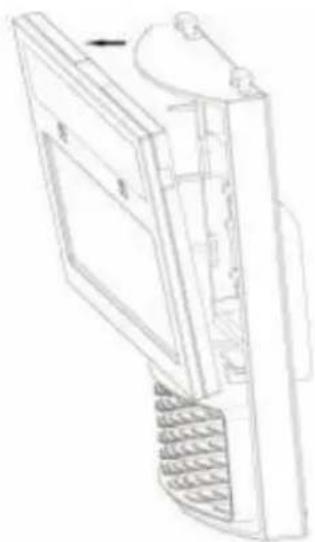
Figure2
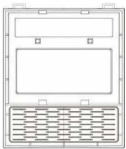
Figure3
Figure4
YH CONSULTING LIMITED. C/O YH Consulting Limited Office 147, Centurion House, London Road, Staines-upon-Thames, Surrey, TW18 4AX
| EC | REP |
Affordable. Reliable. Home Improvement.
WELDING HELMET
MODEL: BY433E
VEVOR
Affordable. Reliable. Home Improvement.
WELDING HELMET
COMMON PROBLEMS AND REMINDERS
YH CONSULTING LIMITED. C/O YH Consulting Limited Office 147, Centurion House, London Road, Staines-upon-Thames, Surrey, TW18 4A>
| EC | REP |
- VEVOR
- WELDING HELMET
- SAFETY INSTRUCTIONS
- WARNING
- WELDING HELMET SAFETY PRECAUTIONS
- READ BEFORE USING
- SYMBOL USAGE
- INDICATES SPECIAL INSTRUCTIONS
- ARC WELDING HAZARDS
- WELDING HELMETS DO NOT PROVIDE UNLIMITED EYE, EAR, AND FACE PROTECTION
- READ INSTRUCTIONS
- FUMES AND GASES CAN BE HAZARDOUS
- PROPOSITION 65 WARNINGS
- OPERATING INSTRUCTIONS
- LENS DELAY CONTROL
- SENSITIVITY CONTROL
- REPLACING THE BATTERY
- CARTRIDGE AND LENS REPLACEMENT
- FRONT CLEAR COVER LENS
- REPLACING INSIDE CLEAR LENS
- INSIDE LENS COVER
- CHANGE THE SHADE CARTRIDGE
- INSTALLING AN AFTERMARKET MAGNIFYING LENS
- CORRECT DISPOSAL
- REPLACEMENT PARTS
- HEAD SIZE ADJUSTMENT: THE HEADBAND
Brand : Vevor
Model : BY433E
Category : Personal protective equipment