BS-115 - Saw Vevor - Free user manual and instructions
Find the device manual for free BS-115 Vevor in PDF.

| Product Type | Horizontal Metal Band Saw |
| Brand | Vevor |
| Model | BS-115 |
| Power Supply Voltage | 110V / 220V |
| Frequency | 50 Hz / 60 Hz |
| Power | 550 W |
| Maximum Blade Speed | 200 feet per minute (SFM) |
| Rectangular Cutting Capacity | 4 × 6 inches (102 × 152 mm) |
| Blade Length | 60 inches (1524 mm) |
| Angle Capacity | 45° / 90° |
| Number of Speeds | 3 speeds |
| Special Features | Horizontal and vertical cutting, automatic shut-off at end of cut, miter vise scale |
| Automatic Shut-off | Yes, when material is cut |
| Compatible Materials | Metal, plastic, wood, stainless steel, alloy steel, brass, aluminum |
| Included Accessories | General purpose blade (1/2" × 0.025", 6 teeth per inch), vise, blade guide, optional casters |
| Maintenance | Blade lubrication, blade tension and alignment, guide cleaning |
| Safety | Blade guard, switch, automatic shut-off, pulley cover |
| Warranty | Electronic warranty via www.vevor.com/support |
| Spare Parts | Complete parts list provided in the manual |
Frequently Asked Questions - BS-115 Vevor
User questions about BS-115 Vevor
0 question about this device. Answer the ones you know or ask your own.
Ask a new question about this device
Download the instructions for your Saw in PDF format for free! Find your manual BS-115 - Vevor and take your electronic device back in hand. On this page are published all the documents necessary for the use of your device. BS-115 by Vevor.
USER MANUAL BS-115 Vevor
Technical Support and E-Warranty Certificate www.vevor.com/support
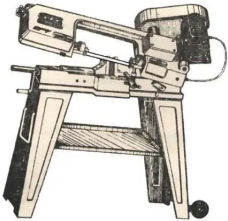
Metal horizontal band saw USER MANUAL
MODEL:BS-115
We continue to be committed to provide you tools with competitive price. "Save Half", "Half Price" or any other similar expressions used by us only represent of savings you might benefit from buying certain tools with us compared top brands and does not necessarily mean to cover all categories of tools offered are kindly reminded to verify carefully when you are placing an order with us actually saving half in comparison with the top major brands.
MODEL:BS-115
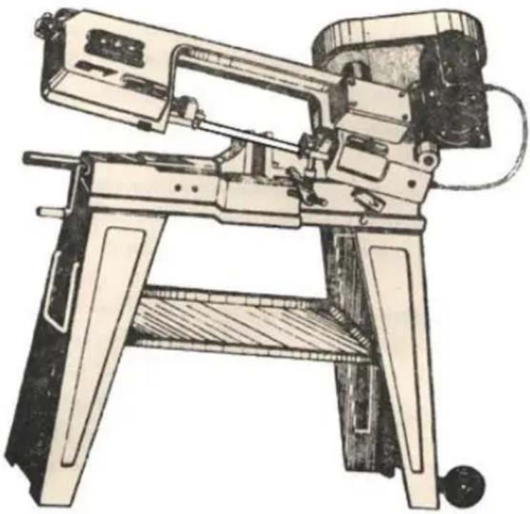
natural_image
Technical line drawing of a mechanical lathe machine with no visible text or symbols(The picture is for reference only, please refer to the actual obje
NEED HELP? CONTACT US!
Have product questions? Need technical support? Please feel fr contact us:
Technical Support and E-Warranty Certificate
www.vevor.com/support
This is the original instruction, please read all manual instruction carefully before operating. VEVOR reserves a clear interpretation user manual. The appearance of the product shall be subject to product you received. Please forgive us that we won't inform you there are any technology or software updates on our product.
 | Warning-To reduce the risk of injury, user must read in manual carefully. |
 | This product is subject to the provision of European Di 2012/19/EC. The symbol showing a wheelie bin crossed through indicates that the product requires separate refus collection in the European Union. This applies to the pr and all accessories marked with this symbol. Products r as such may not be discarded with normal domestic wa must be taken to a collection point for recycling electric electronic devices |
SAFETY
1.Know your band saw. Read the operator's Manual carefully. Learn the operations, applications and limitations.
-
Use recommended accessories. Improper accessories may be hazardous.
-
Wear proper apparel.
-
Keep unnecessary people away.
-
Don't overreach or stand on tool.
-
Avoid dangerous environment. Don't use band saw in damp or wet locations. Keep work area well lighted.
-
Keep work area clean. Cluttered and slippery floors invite accidents.
-
Remove adjusting keys and wrenches from band saw before turning power.
-
Avoid accidental starting. Mark sure switch is off before plugging in power cord.
-
Don't force band saw. It is safe to operate at the cutting rate for was designed.
-
Be specially careful while using band saws in vertical position to k fingers and hands out of the path of blade, both above and beneath table.
-
Never hand hold the material with saw in horizontal position. Alway use the vise, clamp securely.
- Keep belt guard and wheel covers in place and in working order.
- Support long, heavy work from the floor.
- Always remember to switch off the machine when the work is completed.
- Disconnect power cord before adjusting. Servicing and changing black
- Check damaged parts. Damaged parts must be replaced or repaired
- Moving parts should keep in alignment. All adjustments are to be with power disconnected.
- Use a sharp blade and keep tool clean for best and safest perfor
- Safety is a combination of operator's common sense and alertness all times when the saw is functioning.
- Keeping the band saw in top condition is essential for safety.
FEATURES
- Special designed horizontal and vertical band saw.
- Offers three speeds for cutting metal plastic or wood.
3.Shuts off automatically when material is cut. - With scale for the mitering vise.
- No noise while operating.
- Casters (optional) quick and easy moving.
SPECIFICATION
| Item No. | BS-115 |
| Voltage | 110V / 220V |
| Frequency | 50Hz/60Hz |
| Power | 550w |
| Maximum Speed | 200fpm |
| Cut Rectangular Dimensions | 4*6” |
| Blade Length | 60” |
| Capacity | 45°/90° |
ASSEMBLY
- Assemble stand legs on Band Saw Base. See assembly diagram
- Assemble handle vice wheel, tighten set screw.
BLADE GUIDE BEARING ADJUSTMENT
This is the most important adjustment on your saw. It is impossible to satisfactory work from your saw if the blade guides are not properly adjusted. The blade guide bearings for your Metal cutting Band saw is adjusted and power tested with several test cuts before leaving the face to ensure proper settings. The need for adjustment should rarely occur when the saw is used properly. If the guides get out of adjustment, extremely important to readjust immediately. If proper adjustment is not maintained, the blade will not cut straight and if the situation is not corrected, it will cause blade damage.
Because guide adjustment is a critical factor in the performance of you saw, it is always best to try a new blade to see if this will correct cutting before beginning to adjust the bearings. If a blade becomes done one side sooner than the other, for example, it will begin cutting cross simple blade change should correct this problem. More difficult guide adjustment will not.
If a new blade does not correct the problem, check the blade guides proper spacing.
There should be 0.001" clearance between the 0.025" thickness blade guide bearing. To obtain this clearance adjust as follows:
- The inner guide bearing is fixed and cannot be adjusted.
2,.The outer guide bearing is mounted to an eccentric bolt and can I adjusted. - Loosen the nut while holding the bolt with a wrench.
- Position the eccentric by turning the bolt to the desired position of clearance.
- Tighten the nut
- Adjust the second blade guide bearing in the same manner.
- The back edge of the blade should just touch the lip of the Blade Bearing.
BLADE GUIDE ASSEMBLY ADJUSTMENT
The Metal Cutting Band Saw is equipped with two adjustable blade g assemblies. This feature will permit you to adjust the position of the guide for various widths work pieces.
To effect the most accurate cut and prolong the life of the blade. TI guide assemblies should be adjusted to just clear the piece to be cut is done as follows:
- Place the work piece in the vise of band saw and clamp tightly.
- Adjust catch blade guide assembly to the desired position by loosen the hand knobs and positioning the guides required.
- Tighten the hand knobs.
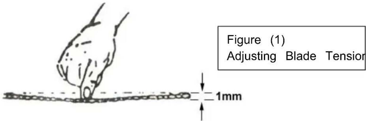
ADJUSTING BLADE TENSION
- Make sure the motor is shut off.
- Press the blade lightly with left hand, make the rear blade against flange of blade wheel and test the blade tension.
- Adjust the blade tension adjustable knob with the right hand until the blade obtains the proper tension.
CHANGING SPEED
- When using your Band Saw, always change the blade speed to be the material being cut. Cutting chart is shown in figure (2).
- Cut off power. Open the pulley guard cover. Loosen the lead screw you are now able to change the position of the belt to gain the speed. Check the belt tension as instructed before. When the tensic belt is well adjusted, lock the motor firmly. Close the pulley guard
MATERIAL CUTTING CHART
| Material, Stainless or Alloy Steel, Bearing Bronzes/Mild Steel, Hard Brass or Bronze Soft Brass/Aluminum Other light materials | Speed (SFM) Belt Groove Used | ||
| 60Hz | Motor Pulley | Saw Pulley | |
| 80FPM | Small | Large | |
| 120FPM | Medium | Medium | |
| 200FPM | Large | Small | |
Figure (2) Material Cutting Chart
BLADE SELECTION
- Special note: 1(1/2" x 0.025"x 641/2min, 651/2max) tooth per inch general use blade is furnished with the metal cutting Band Saw. Additional blades in 10 and 14 tooth sizes are available.
- The choice of blade pitch is governed by the thickness of the work cut; the thinner the work piece, the more teeth advised. A minimum teeth should be in the work piece at all times for proper cutting.
- If the teeth of the blade are so far apart that they straddle the work server damage to the work piece and to the blade can result.
CHANGING BLADE
Raise saw head to vertical position. Loosen blade tension adjustable I sufficiently to allow the saw blade to slip off the wheels. Install the blade as follows:
- Place the blade in between each guide bearing.
- Slip the blade around the motor pulley (bottom) with left hand and position.
- Hold the blade taut against the motor pulley by pulling the blade u with the right hand which is placed at the top of the blade.
- Remove left hand from bottom pulley and it's the top side of the continue the application on the upward pull on the blade.
- Remove right hand from blade and adjust the position of top pulley permit left hand to slip the blade around the pulley using the thumb
index and little finger as guides.
- Adjust the blade tension knob clockwise until it is just right enough blade slippage occurs. Do not tighten excessively.
- Place 2-3 drops of oil on the blade.
- Replace the blade guard.
ADJUSTING THE BLADE TRACKING
This adjustment has been completed and power-tested at the factory. need for adjusting should rarely occur when the saw is used properly tracking goes out of adjusting is listed below:
Step 1: Turn simultaneously with adjusting set screw to make the blade track against the shoulder of the pulley.
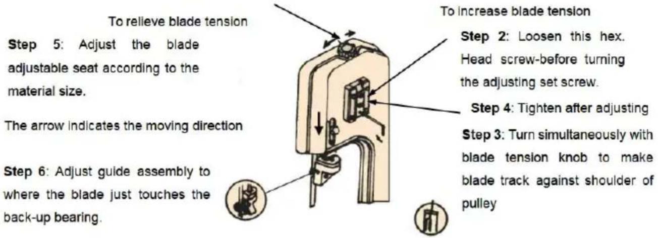
Figure (3)
HORIZONTAL CUTTING OPERATION
Before operating, please read instruction manual and examine every pin including speed, Blade selection, guide assemble position, etc. Operation is as follows:
WORK SET UP
- Raise the saw head to the vertical position.
2.Open the vise to accept the piece to be cut by rotating the wheel end of base (counter clockwise). - Place the work piece on the saw bed. If the price is long, support
- Clamp the work piece securely in the vise by rotating the hand when clockwise.
CUTTING
Close switch, letting the head down slowly onto the work, Do not drop force. Let the weight of the saw head provide the cutting force. The automatically shuts off at end of the cut.
Method of adjusting blade:
A. Loosen the screw #11.
B. Adjust the blade adjustable seat #64 to make the blade vertical to
C. Place the square on the bed to check if the blade is vertical, if repeat the process A to C.
D. Tighten the screw #11.
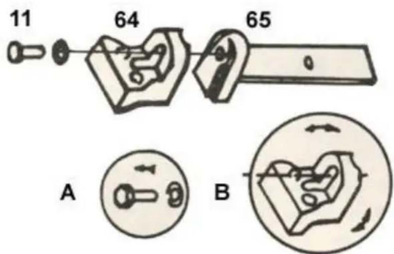
Figure (4)
Adjusting the blade
LUBRICATION
Lubricate the following components using lubricant, L-HV32
- Ball bearing -none.
- Blade guide bearing-none
- Driven wheel bearing-none.
-
Vise lead screw- as needed.
-
The driven gears run in the bath and will not require a lubricant or more than then once a year. When needing a change, first put down bead to a Horizontal position, then loosen 4 screw (#75) of the gear open the cover (#93). Placing a pan under the tight lower corner of gear box, slowly raise the head until the oil flows out, Lower corner
gear box, slowly raise the head until the oil flows out, Lower head wipe up excess oil and foreign matter with soft rags. Then add lut into the box until it is full and not flow over. Close the cover, tigh screws.
THE VERTICAL CUTTING PLATE ASSEMBLY DRAWING.
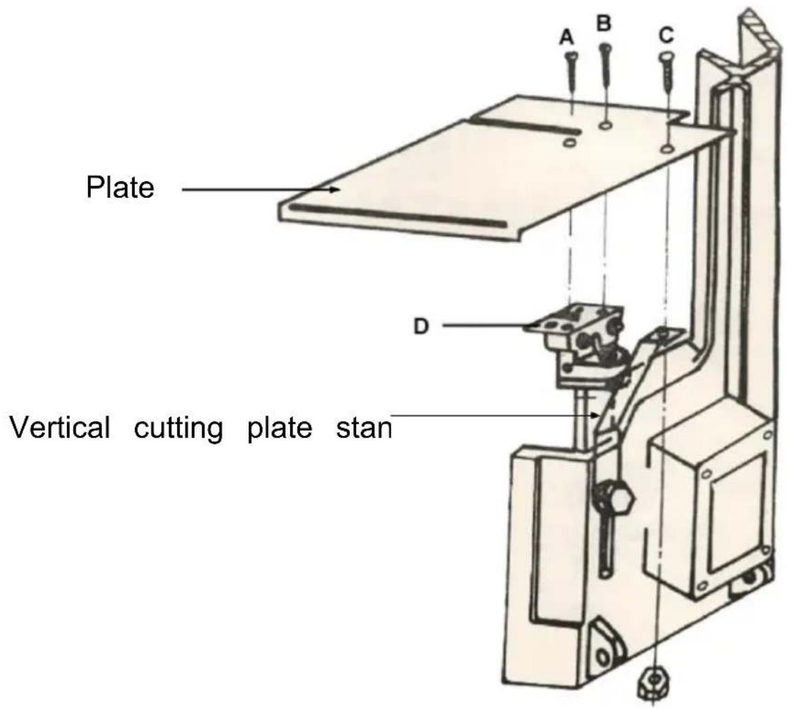
Steps for assembling:
-
Loosen the A.B.C. three screws from the blade guide. And take aw part "D"
-
To lock the vertical cutting plate stand on the valve.
-
To put the plate on the guide and vertical cutting plate stand, then the A.B.C. three screws.
-
Please operate the vertical cutting.
-
Use the miter gauge in the work table grooves to obtain any angle 45 degrees either left or right.
CAUTION-The use of any other accessories may be hazardous.
CAUTION-Always use push sticks particularly when cutting small pieces
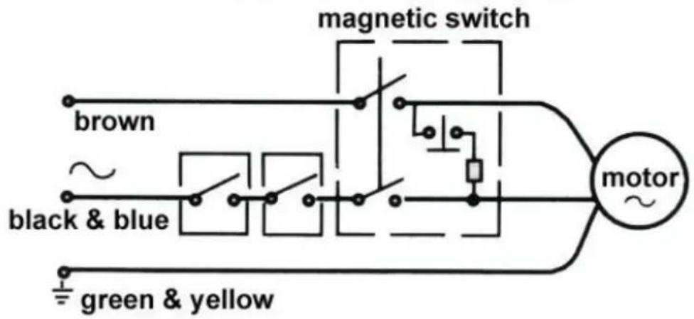
WIRING DIAGRAM
The manual of V shape fixed plate
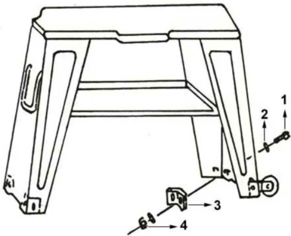
- Hexagon head screw
8PCS - Washer
16PCS - V. shape fixed plate
4PCS - Hexagon nut
8PCS
TROUBLESHOOTING CHART
| Symptom | Possible Cause (s) | Corrective Action |
| Excessive Blade Breakage | 1.Material loose in vise2.Incorrect speed or feed3.Blade teeth spacing too large4.Material too coarse5.Incorrect blade tension6.Teeth in contact with material before saw is started7.Blade rubs on wheel flange8.Misaligned guide bearings9.Cracking at weld | 1.Clamp work securely2.Adjust speed or feed3.Replace with a small teeth spacing blade4.Use a blade of slow speed small teeth spacing5.Adjust where blade just does not slip on wheel6.Place blade in correct with after motor is started7.Adjust wheel alignment8.Adjust guide bearings9.Weld again, note the weld s |
| Premature Blade Dulling | 1. Teeth too coarse2. Too much speed3. Inadequate feed pressure4. Hard spots or scale on material5. Work hardening of material6. Blade twist7. Insufficient blade | 1. Use finer teeth2. Decrease speed3. Decrease spring tension on side of saw4. Reduce speed, in crease feed pressure5. Increase feed pressure by reducing spring tension6. Replace with a new blade, and adjust blade tension7. Tighten blade tension adjustable knob |
| Unusual Wear on Side/Back of Blade | 1. Blade guides worn2. Blade guide bearings not adjusted properly3. Blade guide bearing bracket is loose | 1. Replace2. Adjust as per operators manual3. Tighten |
| Teeth Ripping from Blade | 1. Tooth too coarse for work2. Too heavy pressure, too slow speed3. Vibrating work piece4. Gullets loading | 1. Use finer tooth blade2. Decrease pressure, increase speed3. Clamp work piece securely4. Use coarse tooth blade or brush to remove chips |
| Motor running too hot | 1. Blade tension too high2. Drive belt tension too high3. Gears need lubrication4. Cut is binding blade5. Gears aligned improperly | 1. Reduce tension on blade2. Reduce tension on drive bell3. Check oil bath4. Decrease feed and speed5. Adjust gears so that worm in center of gear |
| Bad Cuts | 1. Feed pressure too great2. Guide bearing not adjusted properly3. Inadequate blade tension4. Dull blade5. Speed incorrect6. Blade guide spaced out to much7. Blade guide assembly loose8. Blade truck too far away from wheel flanges | 1. Reduce pressure by increasing spring tension or side of saw2. Adjust guide bearing, the clearance can not be greater than 0.001mm3. Increase blade tension by adjust blade tension4. Replace blade5. Adjust speed6. Adjust guides space7. Tighten8. Re-track blade according to operating instructions |
| Bad Cuts (Rough) | 1. Too much speed or feed2. Blade is too coarse3. Blade tension loose | 1. Decrease speed or feed2. Replace with finer blade3. Adjust blade tension |
| Blade is twisting | 1. Cut is binding blade2. Too much blade tension | 1. Decrease feed pressure2. Decrease blade tension |
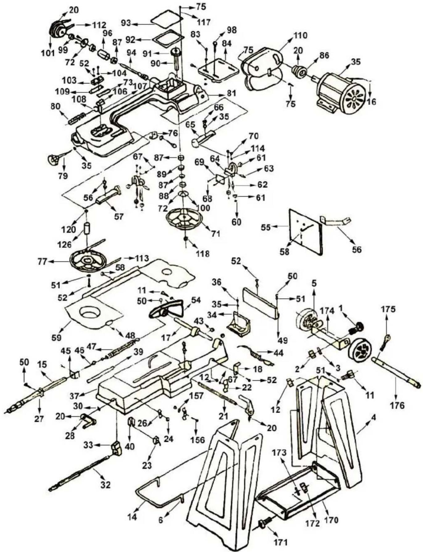
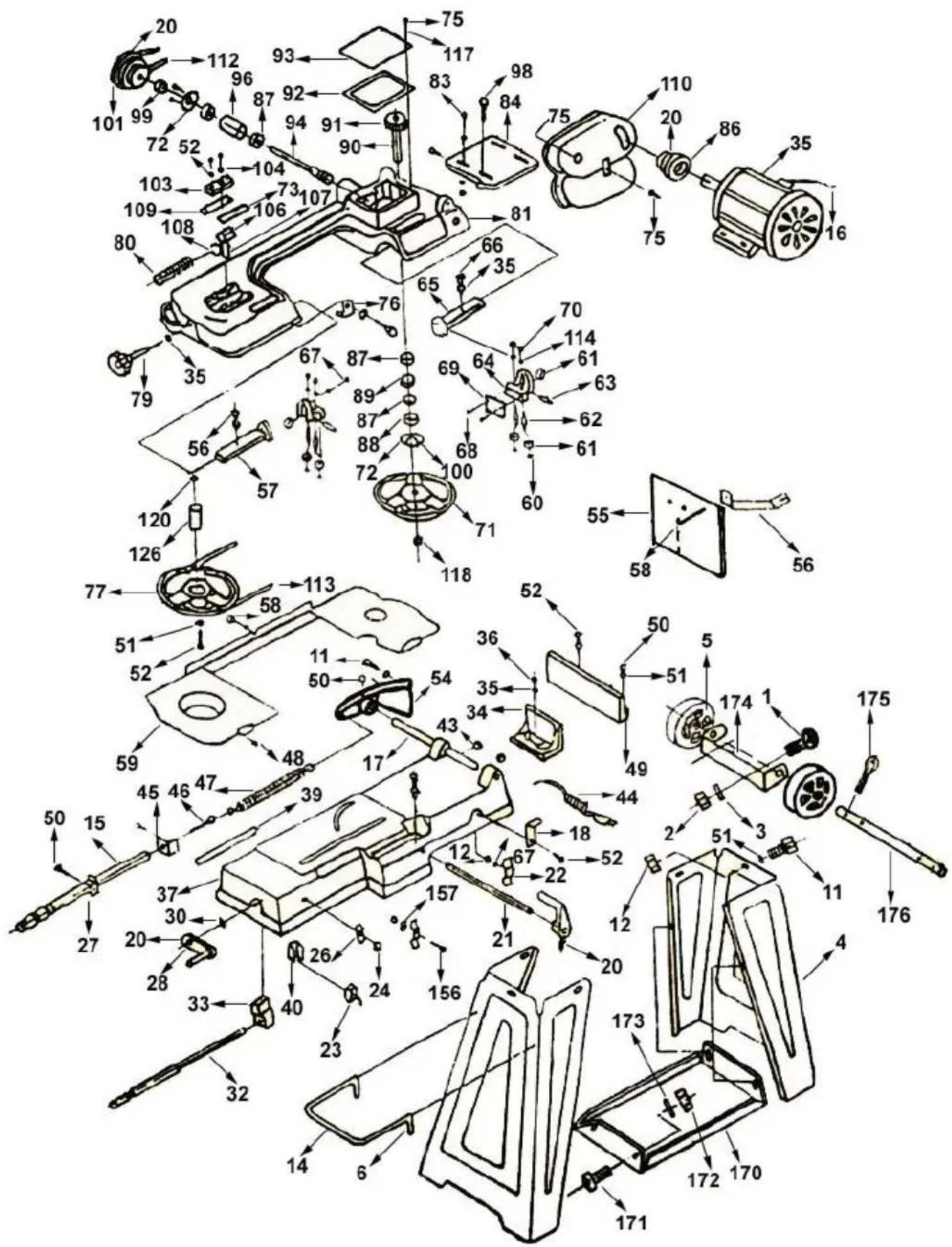
PARTS LIST
| Parts No. | Description | Quantity required |
| 1 | Hexagon head screw | 2 |
| 2 | Hexagon nut | 2 |
| 3 | Washer | 4 |
| 4 | Floor stand (right) | 1 |
| 5 | Wheel assay (optional) | 1 |
| 6 | Cotter pin | 2 |
| 11 | Hexagon head screw | 13 |
| 12 | Hexagon nut | 10 |
| 13 | Floor stand (left) | 1 |
| 14 | Floor stand handle (optional) | 1 |
| 15 | Adjusting rod | 1 |
| 16 | Electric cord | 1 |
| 17 | Pivoting rod | 1 |
| 18 | Support plate | 1 |
| 19 | Stock stop | 1 |
| 20 | Hexagon socket headless screw | 1 |
| 21 | Stock stop rod | 1 |
| 22 | Wire relief retainer | 1 |
| 23 | Switch | 1 |
| 24 | Hexagon nut | 1 |
| 26 | Switch panel | 1 |
| 27 | Adjusting rod support | 1 |
| 28 | Hand wheel | 1 |
| 30 | Thrust washer | 1 |
| 32 | Lead screw | 1 |
| 33 | Vise nut | 1 |
| 34 | Movable vise plate | 1 |
| 35 | Washer | 1 |
| 36 | Hexagon head screw | 1 |
| 37 | Bed | 1 |
| 39 | Scale | 1 |
| 40 | Electric cord cover | 1 |
| 43 | Rubber ring | 2 |
| 44 | Electric cord | 1 |
| 45 | Nut plate | 2 |
| 46 | Spring adjusting screw | 1 |
| 47 | Spring | 1 |
| 48 | Screw | 4 |
| 49 | Mitering vise plate | 1 |
| 50 | Hexagon head screw | 1 |
©
100 Screw 6
101 Worm gear pulley 1
103 Blade tension sliding plate 1
104 Hexagon socket headless screw 2
105 Spring pin 1
106 Sliding plate draw block 1
107 Blade wheel shaft 1
108 Shaft block 1
109 Blade tension sliding guides 2
110 Motor pulley cover 1
112 Belt 1
113 Blade 2
114 Washer 2
117 Washer 1
118 Thrust washer 1
120 Bearing 1
121 Round head cross socket screw 1
122 Hexagon nut 3
126 Bushing 1
131 Switch protection bracket 1
132 Blade safe guard 2
134 Screw 4
140 Hexagon nut 4
156 Round head cross socket screw 3
157 Star washer 1
169 Cross socket screw 2
170 Tool plate 1
171 Hexagon head screw 4
172 Hexagon nut 4
173 Washer 4
174 Wheel stand 1
175 Cotter pin 4
176 Axle 1
Part Assembly Drawing
Packing List
| No. | Descriotion | Quantity | Notes |
| 1 | Main body | 1 Set | |
| 2 | Legs | 1 Set | |
| 3 | Leg Handle | 1 Pc | |
| 4 | Motor | 1 Set | |
| 5 | Motors Driving Pulley | 1 Pc | |
| 6 | Belt Covers | 1 Set | |
| 7 | Belt | 1 Pc | |
| 8 | Vertical Cutting Plate | 1 Pc | |
| 9 | Vertical Cutting Plate Sta | 1 Pc | |
| 10 | Stock Stop Rod | 1 Pc | |
| 11 | Stock Stop | 1 Pc | |
| 12 | Wheel Stand | 1 Pc | |
| 13 | Wheel Stand Axle | 1 Pc | |
| 14 | Wheel | 2 Pcs | |
| 15 | Tool Shelf | 1 Pc | |
| 16 | Fasteners | 1 Set | |
| 17 | Instruction | 1 Copy | |
| 18 | Packing List | 1 Copy |
VEVOR®
TOUGH TOOLS, HALF PRICE
Technical Support and E-Warranty Certificate www.vevor.com/support
VEVOR®
TOUGH TOOLS, HALF PRICE
We continue to be committed to provide you tools with competitive price. "Save Half", "Half Price" or any other similar expressions used by us only represent of savings you might benefit from buying certain tools with us compared top brands and does not necessarily mean to cover all categories of tools offered are kindly reminded to verify carefully when you are placing an order with us actually saving half in comparison with the top major brands.
MODÈLE : BS-115

natural_image
Technical line drawing of a mechanical lathe machine with no visible text or symbolsNEED HELP? CONTACT US!
Have product questions? Need technical support? Please feel fr contact us:
Technical Support and E-Warranty Certificate www.vevor.com/support
This is the original instruction, please read all manual instruction carefully before operating. VEVOR reserves a clear interpretation user manual. The appearance of the product shall be subject to product you received. Please forgive us that we won't inform you there are any technology or software updates on our product.
CHANGER DE VITESSE
Step 1: Turn simultaneously with adjusting set screw to make the blade track against the shoulder of the pulley.
To relieve blade tension
Step 5: Adjust the blade adjustable seat according to the material size.
The arrow indicates the moving direction
Step 6: Adjust guide assembly to where the blade just touches the back-up bearing.
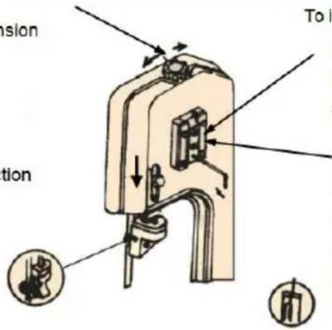
To increase blade tension
Step 2: Loosen this hex. Head screw-before turning the adjusting set screw.
Step 4: Tighten after adjusting
Step 3: Turn simultaneously with blade tension knob to make blade track against shoulder of pulley
Figure (3)
OPÉRATION DE COUPE HORIZONTALE
Étapes de montage :
Liste de colisage
www.vevor.com/support
Horizontale Metallbandsäge BENUTZERHANDBUCH
MODELL: BS-115
We continue to be committed to provide you tools with competitive price. "Save Half", "Half Price" or any other similar expressions used by us only represent of savings you might benefit from buying certain tools with us compared top brands and does not necessarily mean to cover all categories of tools offered are kindly reminded to verify carefully when you are placing an order with us actually saving half in comparison with the top major brands.
MODELL: BS-115

natural_image
Technical line drawing of a mechanical lathe machine with no visible text or symbolsNEED HELP? CONTACT US!
Have product questions? Need technical support? Please feel fr contact us:
Technical Support and E-Warranty Certificate www.vevor.com/support
This is the original instruction, please read all manual instruction carefully before operating. VEVOR reserves a clear interpretation user manual. The appearance of the product shall be subject to product you received. Please forgive us that we won't inform you there are any technology or software updates on our product.
Step 1: Turn simultaneously with adjusting set screw to make the blade track against the shoulder of the pulley.
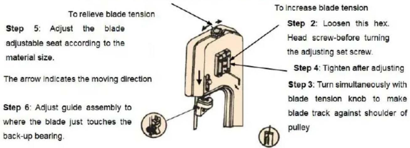
Figure (3)
Packliste
www.vevor.com/support
VEVOR®
TOUGH TOOLS, HALF PRICE
We continue to be committed to provide you tools with competitive price. "Save Half", "Half Price" or any other similar expressions used by us only represent estimate of savings you might benefit from buying certain tools with us compared top brands and does not necessarily mean to cover all categories of tools offered are kindly reminded to verify carefully when you are placing an order with us actually saving half in comparison with the top major brands.
MODELLO: BS-115

natural_image
Technical line drawing of a mechanical lathe machine with no visible text or symbolsNEED HELP? CONTACT US!
Have product questions? Need technical support? Please feel fr contact us:
Technical Support and E-Warranty Certificate www.vevor.com/support
This is the original instruction, please read all manual instruction carefully before operating. VEVOR reserves a clear interpretation user manual. The appearance of the product shall be subject to product you received. Please forgive us that we won't inform you there are any technology or software updates on our product.
Step 1: Turn simultaneously with adjusting set screw to make the blade track against the shoulder of the pulley.
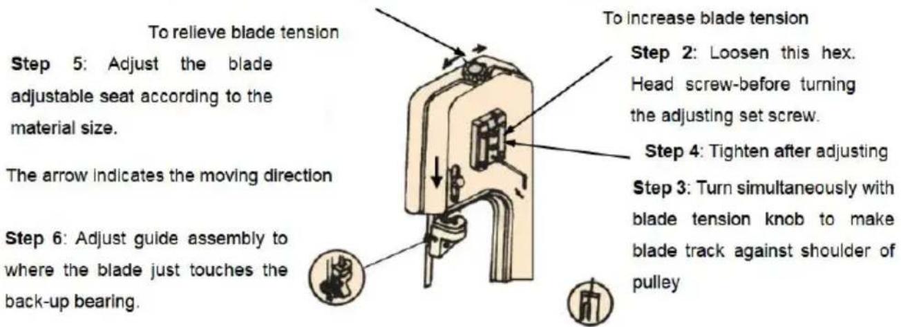
Figure (3)
Lista imballaggio
We continue to be committed to provide you tools with competitive price. "Save Half", "Half Price" or any other similar expressions used by us only represent estimate of savings you might benefit from buying certain tools with us compared top brands and does not necessarily mean to cover all categories of tools offered are kindly reminded to verify carefully when you are placing an order with us actually saving half in comparison with the top major brands.
MODELO: BS-115

natural_image
Technical line drawing of a mechanical lathe machine with no visible text or symbolsNEED HELP? CONTACT US!
Have product questions? Need technical support? Please feel fr contact us:
Technical Support and E-Warranty Certificate www.vevor.com/support
This is the original instruction, please read all manual instruction carefully before operating. VEVOR reserves a clear interpretation user manual. The appearance of the product shall be subject to product you received. Please forgive us that we won't inform you there are any technology or software updates on our product.
CAMBIO DE VELOCIDAD
Step 1: Turn simultaneously with adjusting set screw to make the blade track against the shoulder of the pulley.
To relieve blade tension
Step 5: Adjust the blade adjustable seat according to the material size.
The arrow indicates the moving direction
Step 6: Adjust guide assembly to where the blade just touches the back-up bearing.

To increase blade tension
Step 2: Loosen this hex. Head screw-before turning the adjusting set screw.
Step 4: Tighten after adjusting
Step 3: Turn simultaneously with blade tension knob to make blade track against shoulder of pulley
Figure (3)
Lista de embalaje
We continue to be committed to provide you tools with competitive price. "Save Half", "Half Price" or any other similar expressions used by us only represent estimate of savings you might benefit from buying certain tools with us compared top brands and does not necessarily mean to cover all categories of tools offered are kindly reminded to verify carefully when you are placing an order with us actually saving half in comparison with the top major brands.
MODEL: BS-115

natural_image
Technical line drawing of a mechanical lathe machine with no visible text or symbolsNEED HELP? CONTACT US!
Have product questions? Need technical support? Please feel fr contact us:
Technical Support and E-Warranty Certificate www.vevor.com/support
This is the original instruction, please read all manual instruction carefully before operating. VEVOR reserves a clear interpretation user manual. The appearance of the product shall be subject to product you received. Please forgive us that we won't inform you there are any technology or software updates on our product.
ZMIANA PRĘDKOŚCI
Step 1: Turn simultaneously with adjusting set screw to make the blade track against the shoulder of the pulley.
To relieve blade tension
Step 5: Adjust the blade adjustable seat according to the material size.
The arrow indicates the moving direction
Step 6: Adjust guide assembly to where the blade just touches the back-up bearing.
To increase blade tension
Step 2: Loosen this hex. Head screw-before turning the adjusting set screw.
Step 4: Tighten after adjusting
Step 3: Turn simultaneously with blade tension knob to make blade track against shoulder of pulley
Figure (3)
Etapy montażu:
www.vevor.com/support
VEVOR®
TOUGH TOOLS, HALF PRICE
Technisch Ondersteuning en E-garantiecertificaat www.vevor.com/support
Metalen horizontale lintzaag GEBRUIKERSHANDLEIDING
MODEL: BS-115
We continue to be committed to provide you tools with competitive price. "Save Half", "Half Price" or any other similar expressions used by us only represent estimate of savings you might benefit from buying certain tools with us compared top brands and does not necessarily mean to cover all categories of tools offered are kindly reminded to verify carefully when you are placing an order with us actually saving half in comparison with the top major brands.
MODEL: BS-115

natural_image
Technical line drawing of a mechanical lathe machine with no visible text or symbolsNEED HELP? CONTACT US!
Have product questions? Need technical support? Please feel fr contact us:
Technical Support and E-Warranty Certificate
www.vevor.com/support
This is the original instruction, please read all manual instruction carefully before operating. VEVOR reserves a clear interpretation user manual. The appearance of the product shall be subject to product you received. Please forgive us that we won't inform you there are any technology or software updates on our product.
SNELHEID VERANDEREN
Step 1: Turn simultaneously with adjusting set screw to make the blade track against the shoulder of the pulley.
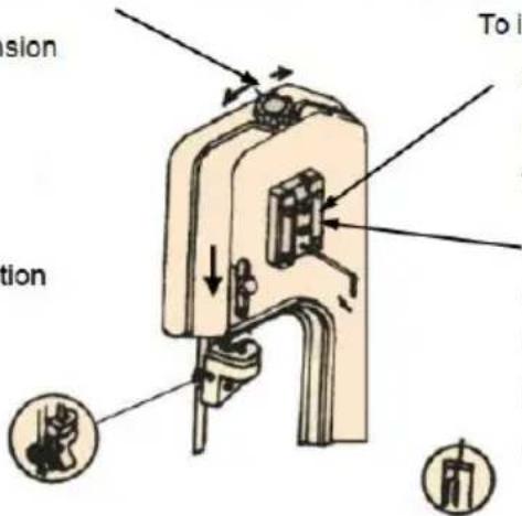
To relieve blade tension
Step 5: Adjust the blade adjustable seat according to the material size.
The arrow indicates the moving direction
Step 6: Adjust guide assembly to where the blade just touches the back-up bearing.

To increase blade tension
Step 2: Loosen this hex. Head screw-before turning the adjusting set screw.
Step 4: Tighten after adjusting
Step 3: Turn simultaneously with blade tension knob to make blade track against shoulder of pulley
Figure (3)
HORIZONTALE SNIJWERKZAAMHEDEN
- Zeskantschroef
8STUKS
- Ring
16STUKS
PROBLEEMOPLOSSINGSSCHEMA
Paklijst
www.vevor.com/support
Horisontell bandsåg i metall ANVÄNDARMANUAL
MODELL: BS-115
We continue to be committed to provide you tools with competitive price. "Save Half", "Half Price" or any other similar expressions used by us only represent of savings you might benefit from buying certain tools with us compared top brands and does not necessarily mean to cover all categories of tools offered are kindly reminded to verify carefully when you are placing an order with us actually saving half in comparison with the top major brands.
MODELL: BS-115
natural_image
Technical line drawing of a mechanical lathe machine with no visible text or symbolsNEED HELP? CONTACT US!
Have product questions? Need technical support? Please feel fr contact us:
Technical Support and E-Warranty Certificate
www.vevor.com/support
This is the original instruction, please read all manual instruction carefully before operating. VEVOR reserves a clear interpretation user manual. The appearance of the product shall be subject to product you received. Please forgive us that we won't inform you there are any technology or software updates on our product.
ÄNDRING HASTIGHET
Step 1: Turn simultaneously with adjusting set screw to make the blade track against the shoulder of the pulley.
To relieve blade tension
Step 5: Adjust the blade adjustable seat according to the material size.
The arrow indicates the moving direction
Step 6: Adjust guide assembly to where the blade just touches the back-up bearing.

To increase blade tension
Step 2: Loosen this hex. Head screw-before turning the adjusting set screw.
Step 4: Tighten after adjusting
Step 3: Turn simultaneously with blade tension knob to make blade track against shoulder of pulley
Figure (3)
HORISONTALT SKÄRNINGSFUNKTION
Steg för montering:
- Sexkantskruv 8 st
- Bricka 16 st
- V. form fast platta 4 st
- Sexkantmutter 8 st
FELSÖKNINGSSCHEMA
DEL A smontering D drawing
Packlista
www.vevor.com/support