
CY5002 - Heating Vevor - Free user manual and instructions
Find the device manual for free CY5002 Vevor in PDF.
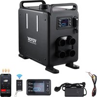


| Brand | Vevor |
| Model | CY5002 |
| Product Type | Diesel Air Heater |
| Heating Power | 8 kW |
| Heat Transfer Fluid | Air |
| Fuel | Light Diesel (Diesel) |
| Power Supply | 12-24 V DC, 40 W |
| AC Adapter | 100-240 V~, 50-60 Hz, 12 V / 12 A |
| Control Mode | Manual (6 speeds H1-H6) and Automatic (0-40 °C) |
| Timer | Programmable (on/off, weekly cycle) |
| Remote Control | Yes, 433 MHz, 24-bit |
| Bluetooth Connectivity | Yes, AirHeaterCC app |
| Carbon Monoxide Detector | Yes, alarm at 500 ppm, automatic shutdown |
| Overheating Protection | Yes (housing > 230°C) |
| Operating Ambient Temperature | -20°C to 50°C |
| Max Altitude (Plateau Mode) | Yes, air/fuel ratio adjustment |
| Installation | Requires a professional; horizontal orientation, exhaust outlet to the outside |
| Package Contents | Main engine, controller, wiring harnesses, hoses, adapter, remote control, CO detector, manual |
| Certifications | FCC (Part 15), CE (WEEE Directive 2012/19/EC) |
| Warranty and Support | Electronic warranty certificate at www.vevor.com/support |
Frequently Asked Questions - CY5002 Vevor
User questions about CY5002 Vevor
0 question about this device. Answer the ones you know or ask your own.
Ask a new question about this device
Download the instructions for your Heating in PDF format for free! Find your manual CY5002 - Vevor and take your electronic device back in hand. On this page are published all the documents necessary for the use of your device. CY5002 by Vevor.
USER MANUAL CY5002 Vevor
Technical Support and E-Warranty Certificate www.vevor.com/support
DIESEL HEATER
We continue to be committed to provide you tools with competitive price. "Save Half", "Half Price" or any other similar expressions used by us only represents an estimate of savings you might benefit from buying certain tools with us compared to the major top brands and does not necessarily mean to cover all categories of tools offered by us. You are kindly reminded to verify carefully when you are placing an order with us if you are actually saving half in comparison with the top major brands.
VEVOR®
TOUGH TOOLS, HALF PRICE
DIESEL HEATER
MODEL: CY-5002 MODEL: CY-5004
NEED HELP? CONTACT US!
Have product questions? Need technical support? Please feel free to contact us:
Technical Support and E-Warranty Certificate www.vevor.com/support
This is the original instruction. Please read all manual instructions carefully before operating. VEVOR reserves a clear interpretation of the user manual. The appearance of the product shall be subject to the product you received. Please forgive us that we won't inform you if there are any technology or software updates on our product.
| Symbol | Symbol Description |
 | Warning: To reduce the risk of injury, the user must read instructions manual carefully. |
 | This symbol, placed before a safety comment, indicates a k of precaution, warning, or danger. Ignoring this warning may lead to an accident. To reduce the risk of injury, fire, or electrocution, please always follow the recommendations shown below. |
 | CORRECT DISPOSAL:This product is subject to the provisio European Directive 2012/ 19/EC. The symbol showing a wh bin crossed through indicates that the product requires sepa refuse collection in the European Union. This applies to the product and all accessories marked with this symbol. Produc marked as such may not be discarded with normal domesti waste, but must be taken to a collection point for recycling electrical and electronic devices. |
 | Warning: Toxic material. Take care to avoid coming into contact with toxic material. |
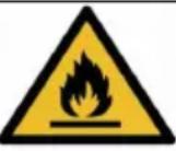 | Warning: Flammable material. Take care to avoid causing a by igniting flammable material. |
SAFETY INSTRUCTION

WARNING:

Read all safety warnings, instructions, illustrations, and specifications provided with this diesel heater. Failure to follow all instructions listed below may result in electric shock, fire, and/or serious injury.
- The following measures shall not be adopted
- Change the important component of the diesel heater.
- Make use of spare parts from other manufacturers without permission.
- Disobey the instruction and guide during installation or operation.
- Only allow using original attachment and spare parts during installation and maintenance.
- The heaters shall not be used in places where they may form flammable or dust, for example:
- Fuel depot • Carbon storehouse
- Timber storehouse
- Granary and similar sites • Diesel/petrol station
And keep away from fuel tanks, compression tanks, fire extinguishers, clothes, other flammable objects.
- Do not use cigarette lighter for startup.
- Do not use the heater in closed and/or unventilated places.
- The heaters shall be turned off when filling fuel.
- Do not cut off the electric power in operation.
- If the fuel leak or discharge from the fuel system of heaters, please contact VEVOR for repair.
- Place the exhaust outlet outside to prevent any penetration of exhaust fumes.
- In the process of work, it is forbidden to cut off the electric power directly to stop the heater from working.
- Seal all gaps between the mounting plate and the car body.
- The machine will stop heating after over-temperature protection. Please do not power off. After the machine is naturally cooled and turned off, it can be restarted.
- After turning off the machine, please do not immediately disconnect the power supply. It takes 3-5 minutes for the machine to stop working completely.
- After starting the machine for 3-5 minutes, it will work normally and heat. Please wait patiently.
- When the heater is just started, the current is relatively high, so an adapter with a voltage of 12V and a current of 15A or greater is required for the power supply.
- This appliance can be used by children aged from 8 years and above and persons with reduced physical, sensory or mental capabilities or lack of experience and knowledge if they have been given supervision or instruction concerning use of the appliance in a safe way and understand the hazards involved. Children shall not play with the appliance. Cleaning and user maintenance shall not be made by children without supervision.
17. WARNING: Flammable material

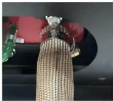
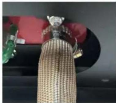
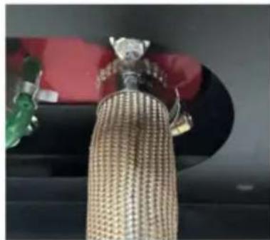
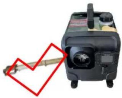
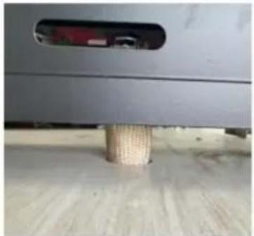
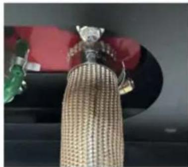
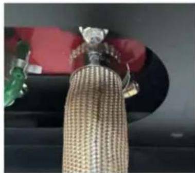
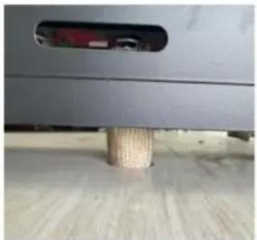
During installation/use, service, and disposal of the appliance, please pay attention that there should be no flammable substances around exhaust pipe. The temperature of the exhaust pipe is very high wh
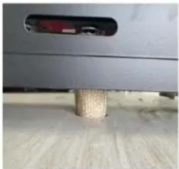
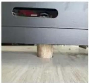
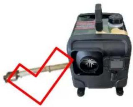
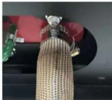
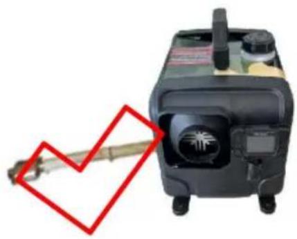
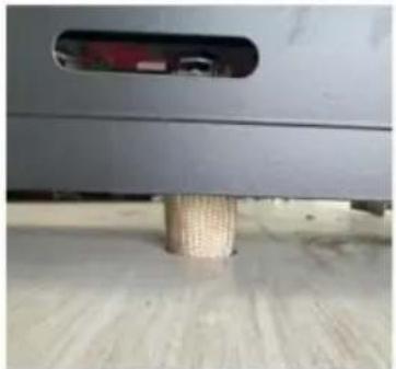
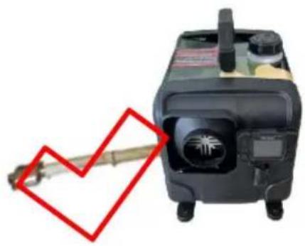
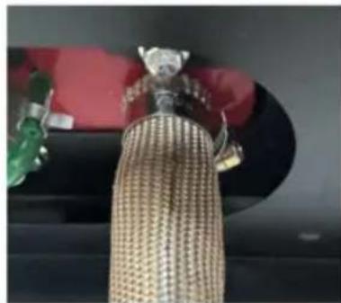
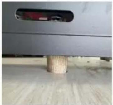
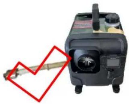
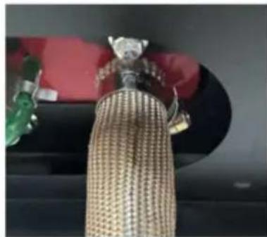
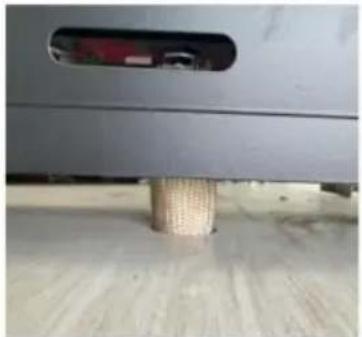
is working. Take care to avoid causing a fire by igniting flammable material. Please strictly follow the following methods to correctly install insulation sleeve on the exhaust pipe and reduce surface temperature:

Installing insulation sleeves on exhaust pipes can effectively reduce surface temperature and prevent fire hazards caused by improper installation.

18. WARNING: Toxic material

- During installation/use, service, and disposal of the appliance, please install the appliance with space for ventilation to prevent carbon monoxide poisoning. Place the exhaust outlet outdoors to prevent exhaust gas from seeping in.
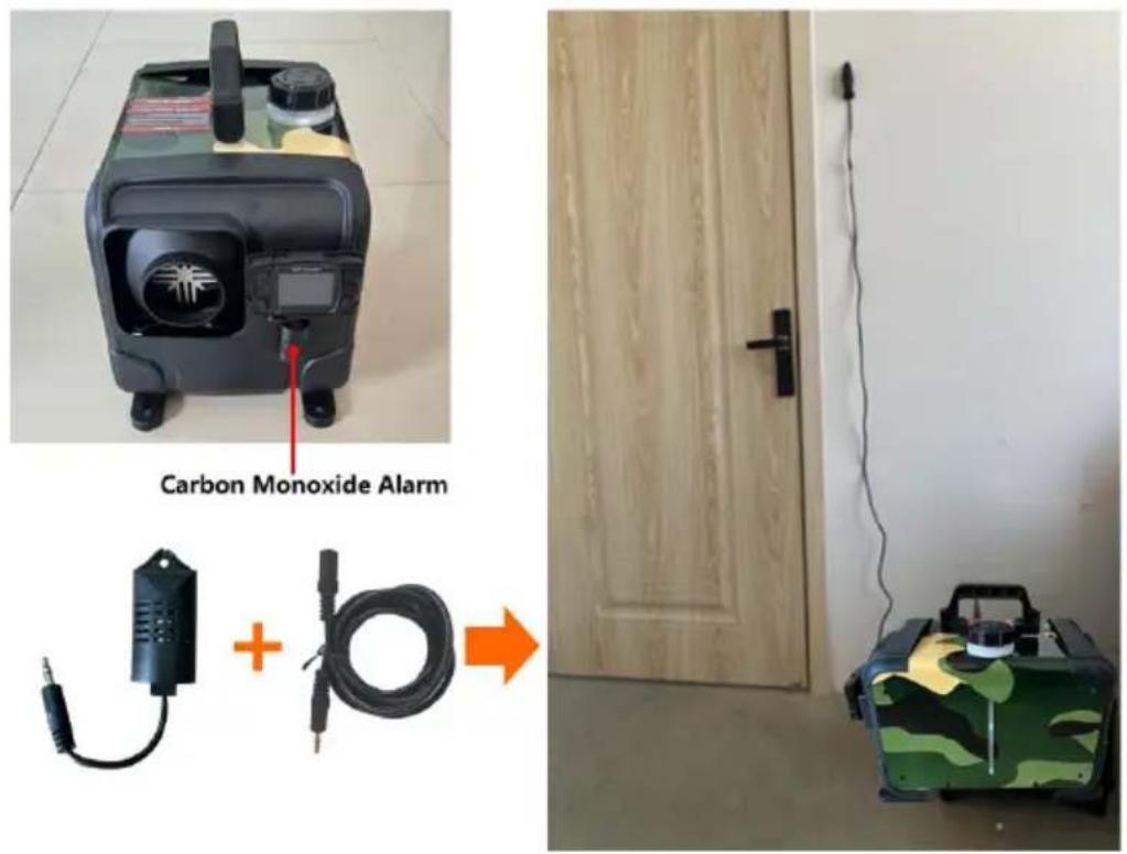
① To prevent the risk of carbon monoxide poisoning caused by improper installation, the product is equipped with a carbon monoxide alarm. When the carbon monoxide content in the enclosed space reaches 300ppm, the LCD will prompt CO to exceed the limit. When the content reaches 500ppm, an alarm will be triggered and the machine will be shut down. The leakage point needs to be checked and repaired immediately before starting up for use.
② The carbon monoxide alarm device is equipped with a 2m extension cable which can install the probe in any position. It is not recommended to install far away from the diesel heater or too close.
SAVE THESE INSTRUCTIONS
FCC INFORMATION
CAUTION: Changes or modifications not expressly approved by the party responsible for compliance could void the user's authority to operate the equipment!
This device complies with Part 15 of the FCC Rules. Operation is subject to the following two conditions:
1) This product may cause harmful interference.
2) This product must accept any interference received, including interference that may cause undesired operation.
WARNING: Changes or modifications to this product not expressly approved by the party responsible for compliance could void the user's authority to operate the product.
Note: This product has been tested and found to comply with the limits for Class B digital device pursuant to Part 15 of the FCC Rules. These limits are designed to provide reasonable protection against harmful interference in a residential installation.
This product generates, uses and can radiate radio frequency energy, and if installed and used in accordance with the instructions, may cause harmful
interference to radio communications. However, there is no guarantee that interference will not occur in a particular installation. If this product does cause harmful interference to radio or television reception, which can be determined by turning the product off and on, the user is encouraged to try to correct the interference by one or more of the following measures.
- Reorient or relocate the receiving antenna.
- Increase the distance between the product and the receiver.
- Connect the product to an outlet on a circuit different from that to which the receiver is connected.
- Consult the dealer or an experienced radio/TV technician for assistance.
PRODUCT FUNCTION
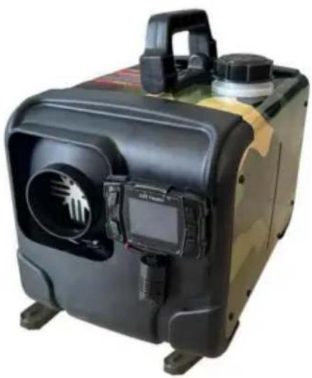
- The diesel heater (hereinafter referred to as the heater) is independent of the original engine system. It makes use of a 12-24V direct current to drive. The heater has two kinds of control modes: Automatic control mode and Manual control mode. The heater adopts light diesel, which corresponds to the environmental temperature as fuel, and it can be started and operated normally at a temperature above 40°C. The inhaled fresh air is heated to hot air through a heat exchanger by the energy that comes from burning fuel, then blown to where it is needed. This type of heater has the advantage of compact structure, lightweight, high thermal efficiency, economy of electricity and fuel, and easy installation.
- The heater gets rid of damage to the car caused by the sudden drop in temperature, improves the temperature inside the car, and preheats the engine coolant to avoid engine wear at low temperature. It is conducive to car interior thawing, car start, and car glass defrosting and defogging.
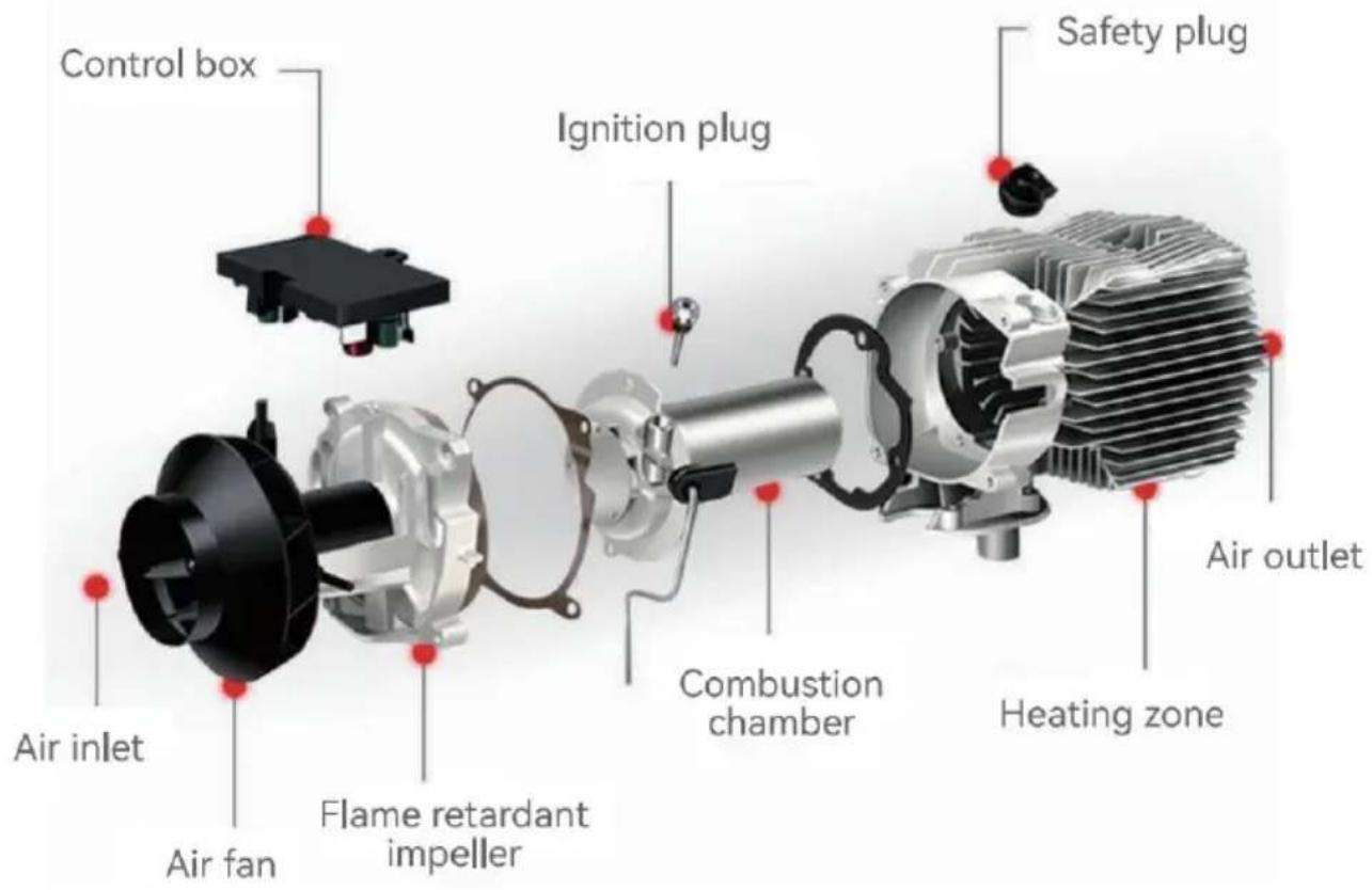
INTERNAL STRUCTURE
INSTALLATION POSITION
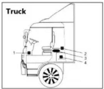
- On the co-driver's legroom.
- On the back wall of the cab.
- Driver's seat backrest.
- Within the tool box.
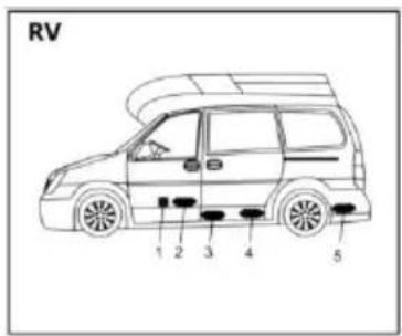
- In front of the passenger seat.
- Between the driver seat and passenger seat
- 3 & 4 under the container.
- In the trunk.
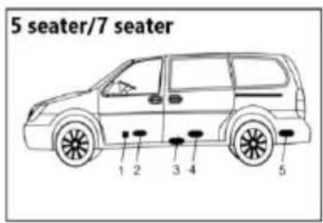
The heater is mainly installed in the passenger room or baggage room of the vehicle. If it is installed, fix the heater under the vehicle, but beware of splashing.

- Inside the driver's seat.
- On the back wall of the ca
- Inside the protection box.
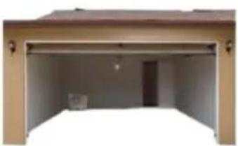
- Installed in the garage against the wall
- There should be no foreign object blocking the front and rear air vents
- No flammable materials around the exhaust pipe
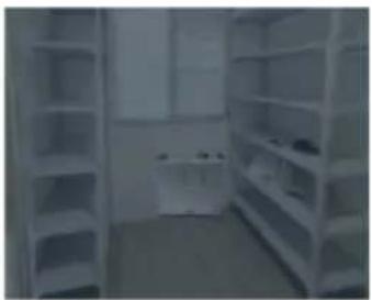
- Installed against the wall of the warehouse
- There should be no foreign objects blocking the front and rear air vents.
- No flammable materials around the exhaust pipe

The installation of the machine requires professional personnel to install it.

It is recommended to use high-grade diesel fuel when refueling diesel heater. Other types of fuels, such as kerosene, vegetable gasoline, waste oil, etc., cannot be used. Otherwise, the heater may have an unpleasant odor and malfunction during operation.
MODEL
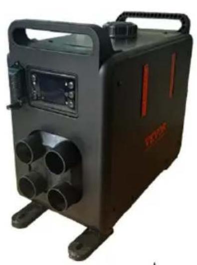
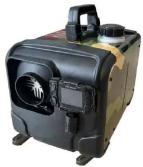
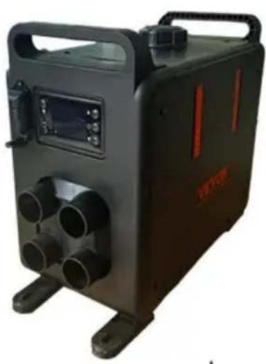
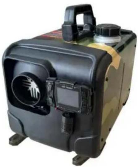
| Model | CY5002 | CY5004 |
| Appearance | 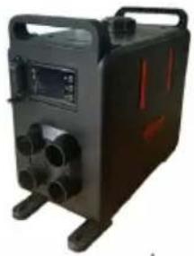 | 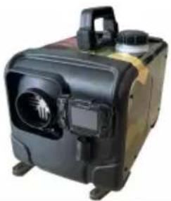 |
| Power ZWH | 8KW | |
| Heating medium | Air | |
| Fuel | Diesel | |
| Ratings | DC12-24V/40W | |
| Adapter | 100-120V~, 50-60Hz, 12V/12A For US users100-240V~, 50-60Hz, 12V/12A For European u | |
PACKING LIST
| Model | CY-5002 | CY-5004 | |
| Main engine |  | 1 | 1 |
| Carbon monoxide module | 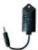 | 1 | 1 |
| Power cord |  | 1 | 1 |
| Extension line |  | 1 | 1 |
| Remote control | [X077] | 1 | 1 |
| Rotary tuyere | 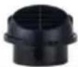 | / | 1 |
| Adapter | 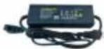 | 1 | 1 |
| Machine fixing piec |  | 4 | 4 |
| User Manual |  | 1 | 1 |
| Silencer with 1 fix piece and 2 screw | 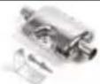 | 1 | 1 |
| Intake pipe |  | 1 | 1 |
| Exhaust pipe | 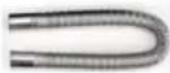 | 1 | 1 |
| Blowpipe |  | 4 | 1 |
| Blowpipe clamp |  | 4 | / |
| Clamp |  | 6 | 6 |
| Pipe clip |  | 2 | 2 |
| Air filter element |  | 1 | 1 |
| Screw for the loc catch |  | 6 | 6 |
| Quick connector |  | / | 1 |
| Protective sleeve |  | 1 | 1 |
| Silencer retaining screw | 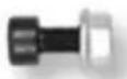 | 1 | 1 |
| Machine fixture bol |  | 4 | 4 |
Refer to the installation diagram below and carefully read the precautions when installing or using:
1. No Side Installation:
※ Side installation of the diesel heater will result in oil leaks inside the machine after a period of use, producing a large amount of smoke and carbon monoxide poisoning. During installation, leave a space of 10cm around the heater to ensure good ventilation.
※ If installing the heater inside a building:
① With the heater placed indoors: Make holes in the wall for the exhaust pipe to be placed outdoors. Pay attention to insulating the exhaust pipe as it can be very hot and could cause a fire. ② With the heater placed outdoors: It's necessary to extend the exhaust pipe to avoid the exhaust from being sucked into the building from the back fan post of the heater, which can lead to carbon monoxide poisoning.
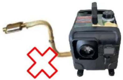
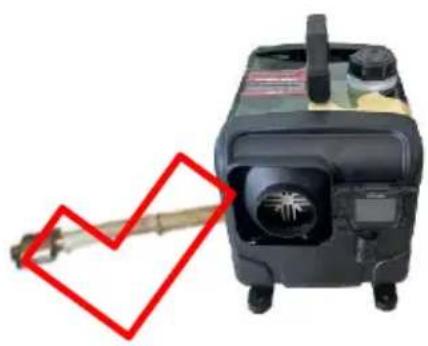
Incorrect Installation Direction Correct Installation Direction
2. Precautions for the power supply:
※ The power supply for the diesel heater must meet the following requirements: Voltage: 12V; Current: ≥20A, either from a direct power source or a battery. If powered by a battery, do not charge the battery while using the heater as insufficient current can cause malfunction. Ensure a firm and secure connection to the battery. Using clamps for fixation can result in poor contact.
※ When extending the power cable for the diesel heater, the wire diameter should be >2mm². Using a thin wire can lead to insufficient current, causing the heater to not work. After connecting, use insulating tape to protect the connection and prevent electrical leakage, which might lead to fires.
※ Do not disconnect the power when the diesel heater is operating at high temperatures. This can cause backfire due to high temperatures. Repeatedly doing so can cause permanent damage. Solutions:
- If power is cut and you immediately turn on the heater: Wait until the intense heat of the heater has completely dissipated before turning it on for normal operation.
- If the heater is turned on a long time after a power cut: Incomplete combustion inside may produce a large amount of smoke. Wait for the smoke to clear, the heater will automatically start and operate normally.

It is recommended to use high-grade diesel fuel when refueling the diesel heater. Other types of fuels, such as kerosene, vegetable oil, gasoline, waste oil, etc., cannot be used. Otherwise, the heater may have an unpleasant odor and malfunction during operation.
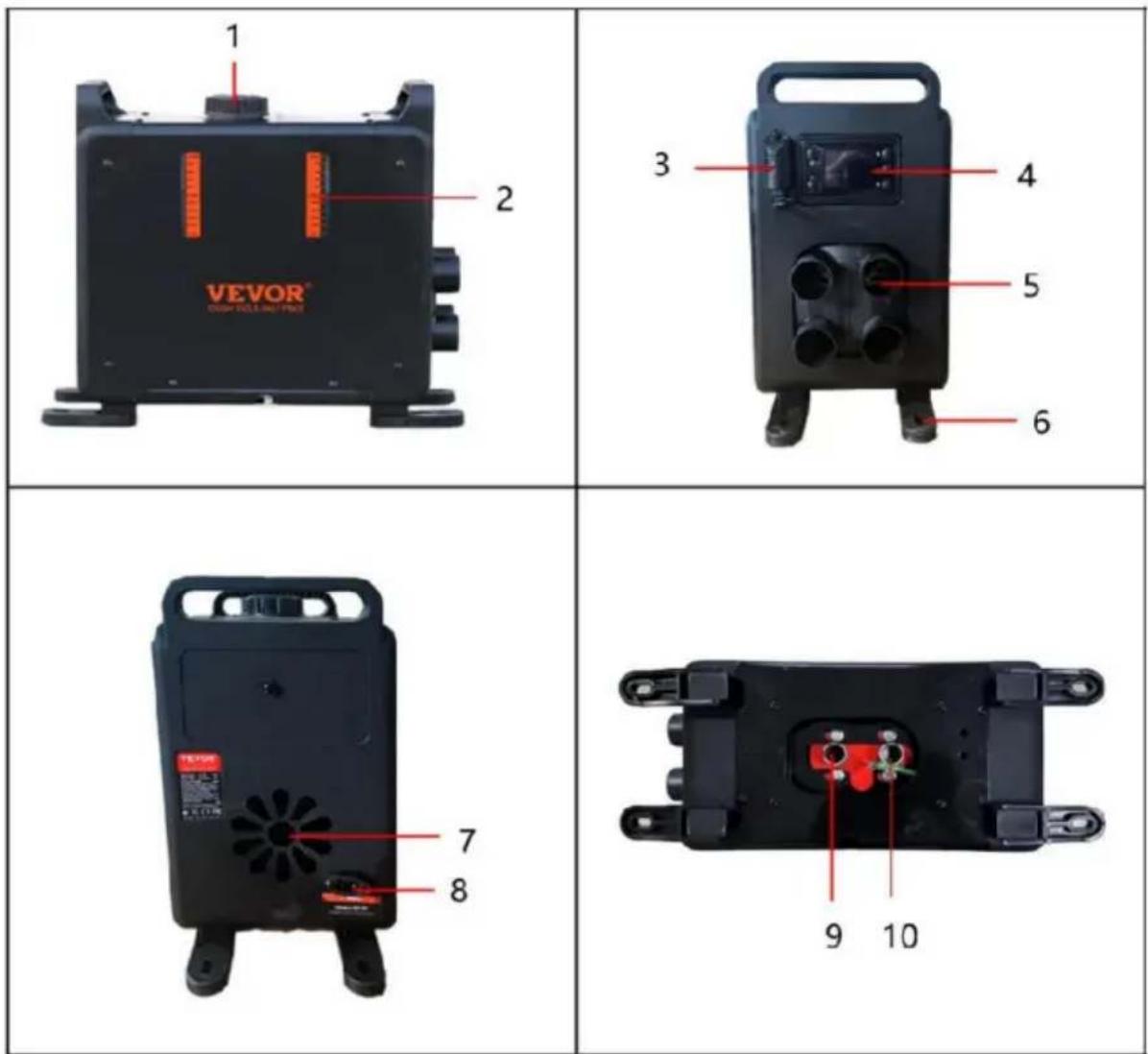
PRODUCT INFORMATION
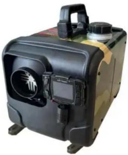
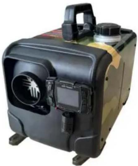
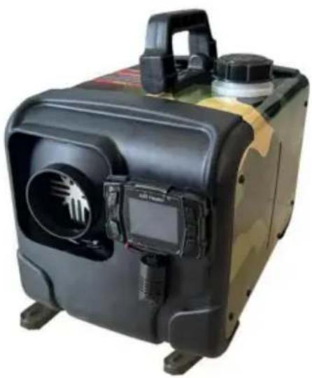
Model: CY-5002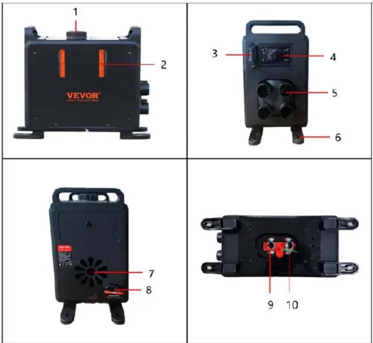
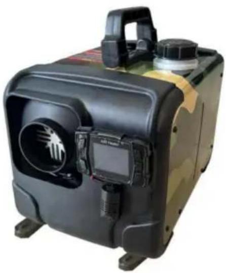
| 1 | Fuel tank port | 2 | Fuel tank scale |
| 3 | Carbon Monoxide Alarm | 4 | liquid crystal shutter |
| 5 | Outlet | 6 | footing |
| 7 | Air inlet | 8 | Power supply port |
| 9 | exhaust port | 10 | Air intake |
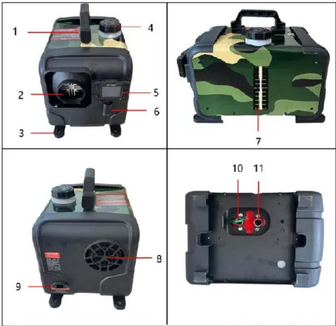
| 1 | handle | 2 | Outlet |
| 3 | footing | 4 | Fuel tank port |
| 5 | liquid crystal shutter | 6 | Carbon Monoxide Alarm |
| 7 | Fuel tank scale | 8 | Air inlet |
| 9 | Power supply port | 10 | Air intake |
| 11 | exhaust port | ||
CY-5002: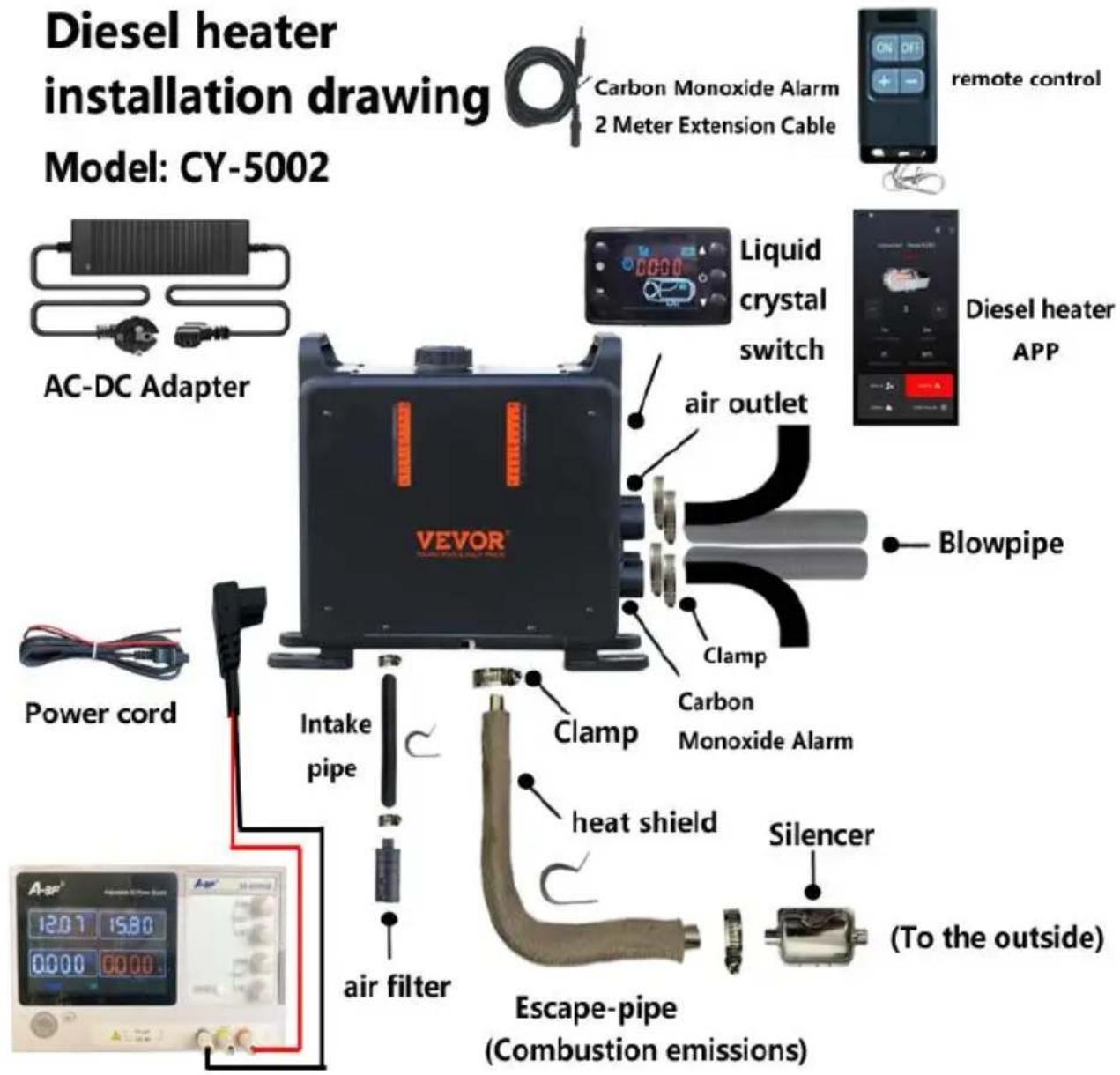

When the heater is just started, the current is relatively high, so an adapter with a voltage of 12-24V and a current of 12A or greater is required for the power supply.
CY-5004:
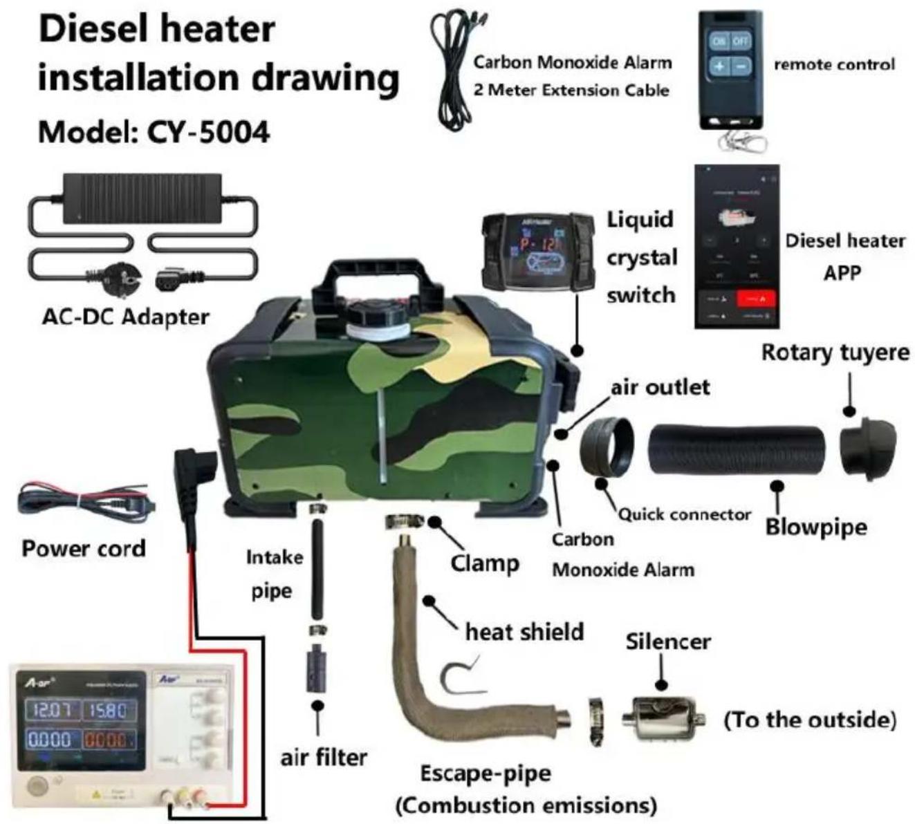

When the heater is just started, the current is relatively high, so an adapter with a voltage of 12-24V and a current of 12A or greater is required for the power supply.

Warning:
- The air inlet shall not be blocked, and keep the inlet open and clear.
- Keep the exhaust pipe clear. The exhaust pipe outlet shall be kept away from anything flammable, and avoid heating and igniting flammable goods and loading cargo on the ground.
- To ensure optimal combustion, please remember that the smoke exhaust pipe cannot be placed upward, but must be placed horizontally or downward.
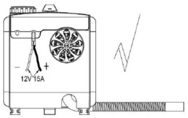
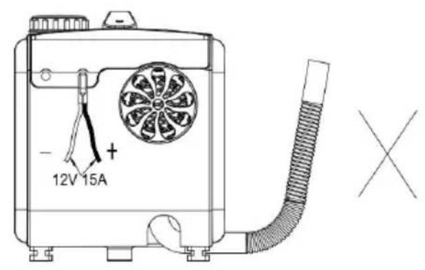
Panel operation instructions
1. The control panel is shown in the following figure
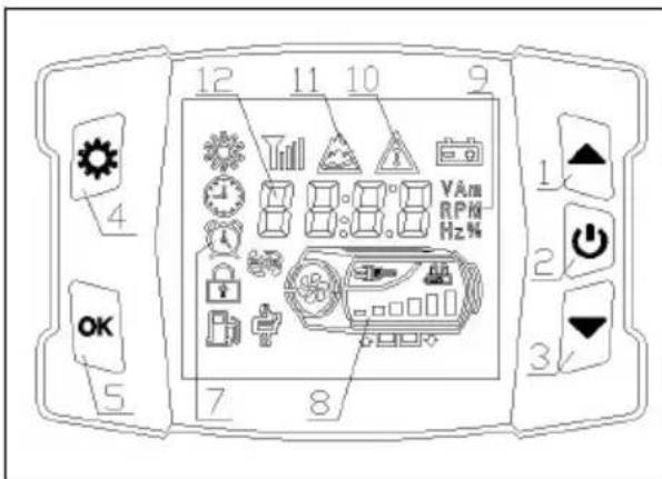
- Adding keys; 2. On/Off button;
3. Subtraction key; 4. Set key;
5. OK key;
- State symbols; 8. Host schematic diagram;
- Data unit; 10. Fault symbols;
- Plateau symbol; 12. Display data parameters;
Display time: The time displayed in standby mode is natural time;
Run time: The time displayed in the startup state is the time when the machine starts running from startup.
II. Usage Operation
1. On/Off Operation
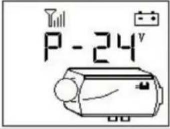 | 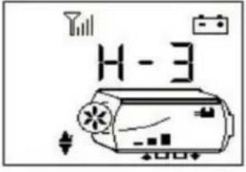 | 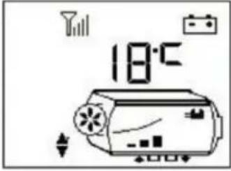 |
| Power off status | Power on status (manual mode) | Power on status (automatic mode) |
1) Power On Operation
In the shutdown state, press and hold the " " button for 2 seconds to turn on the device, and the display will show "Power on status" as shown in the above picture.
2) Shutdown Operation
In the power on state, long press the "button for 2 seconds, and the device enters the shutdown and cooling process, displaying "OFF". After the device cools down, it shuts down and displays the "shutdown status" as shown in the above picture. Do not force power off when displaying "OFF". Power off may damage accessories due to high temperature inside the machine and inability to dissipate heat! Wait until the machine is displayed in the shutdown state before power off!
3) Manual Mode Operation
The manual mode consists of 6 gears (H1-H6). H6 represents the maximum power, as shown in the "power on state" in the figure above. Use the "▲" or "▼" key to increase or decrease the gear.
4) Automatic mode operation
In automatic mode, as shown in the above figure, with a setting of 18°C. Use the "▲" or "▼" keys to increase or decrease the temperature value, and set it to 0-40°C. Long press the " " button for 2 seconds to switch between manual/automatic modes. Automatically upshift/downshift outside the set temperature range of ± 3°C.
2. Switching to display data on startup
Power on status: Short press the " " button to switch between displaying data in the following order:
gear (or set temperature) -> shell temperature -> working voltage -> ambient temperature -> carbon monoxide concentration
3. Temperature unit switching
Simultaneously press and hold the " "+"▲" keys for 2 seconds to switch the temperature unit to "Fahrenheit/Celsius".
4. Manual oiling operation
In the shutdown state, press the "▲▼" button simultaneously for 2
seconds to manually control the oil pump to pump oil. Release the button to stop pumping oil.
5. Plateau mode operation
Simultaneously press and hold the "工厂" + "OK" keys for 2 seconds to enter high-
altitude mode. The icon displays the start of high-altitude mode. In high-altitude mode, the wind oil ratio decreases to adapt to high-altitude hypoxia, and then press and hold the " "+"OK" keys for 2 seconds to exit high-altitude mode.
6. Time on/off time operation
Press and hold the "OK" and "▼" keys for 2 seconds to enter the timer setting interface, and the indicator symbol " " will be displayed. The display shows the shutdown time to be set, not the startup time. If the timer function is enabled, turning off the timer function will turn off the " " symbol.

1) Press the "▲" or "▼" key to adjust the time value. The time adjustment range is from 00:00 to 23:59. 2) Press the ⏻ key to switch and adjust the number position, and the corresponding number will flash. 3) Press the "OK" button or do not operate any button for 15 seconds to save the set value. If you are setting the startup time, switch to the shutdown time setting. Otherwise, exit the timer setting. 4) Press the key to not save the set value. If you are setting the start time, switch to the shutdown time setting. Otherwise, exit the timer setting. 5) In the unset state, press the " " key to cycle through the display of the scheduled time for the day.
After activating the timer function, the clock will automatically start up when it reaches the scheduled startup time; it will automatically shut down when the scheduled shutdown time is reached. When the panel is powered off, the timer function status will be saved, and after power on, the timer function status will be restored.
If the timer function is not manually turned off, as long as the clock reads the scheduled on/off time, the device will automatically turn on/off.
7. Clock synchronization operation
Press and hold the "OK" button for 2 seconds to enter the clock adjustment interface, and the indicator symbol "钟" will be displayed.
1) Press the "▲" or "▼" key to adjust the time value. The time adjustment range is from 00:00 to 23:59. 2) Press the ⚙ key to switch and adjust the number position, and the corresponding number will flash. 3) After adjusting the time, press the "OK" button or do not operate any button for 15 seconds to exit this interface. The phone time will be automatically synchronized when connecting to the App.
8. Remote control matching operation
In the shutdown state, press and hold the "▼" and " " keys for 2 seconds to enter the remote control matching interface, as shown in the following figure.
HFR1
1) Press the "▲" or "▼" key to adjust the storage address: HFA1, HFA2, HFA3, HFA4, corresponding to four remote controls. 2) Select the remote control number, press any key on the remote control, and the machine will successfully match the code and exit the match status. 3) Press the ⏻ key to exit the remote code pairing.
*Remote control requirements: frequency band 433MHz, 24-bit code.
9. Fault alarm
As shown in the figure below, the corresponding fault symbol flashes, and the corresponding faulty component icon flashes. The displayed data is the fault code, and its meaning can be found in the fault table.
![[ - ]](/content/2026/04/734764/images/a362e42909b64233fd04f64225193da3876d9e2bfd99791240e152392590e198.jpg)
*Spark plugs, oil pumps, fans, sensors, power supplies, and other symbols flash to indicate that corresponding components have malfunctioned.
10. This panel supports mobile apps to control this device through Bluetooth.
Instructions for use
- It is prohibited to use in environments with high humidity, conductive dust, flammable and explosive gases, dust, materials, corrosive media, strong light exposure, and strong magnetic, high-voltage, and high current equipment in the vicinity.
- Power supply voltage range: DC24V controller applicable (18-32)V; DC12V controller is suitable for (9-16)V; Different voltage controllers are not interchangeable and are prohibited from exceeding the applicable voltage range.
- Do not open the controller shell without permission.
- The equipment must be installed strictly according to requirements and used under safe conditions.
- When the body is hot and the fan cannot operate normally, it is necessary to quickly cool down the body. Blow cold air into the combustion intake hole to lower the body temperature below 80°C. Prevent high-temperature damage to components or fire.
When heating the equipment, it is necessary to ensure that each air duct is unobstructed and that the pipeline is free of bends, pressures, and blockages in order to effectively ensure the heating efficiency and normal operation of the equipment. Blocked channels can cause high temperatures in the body, reduce heating efficiency, shorten equipment lifespan, or damage equipment. The use of qualified fuel is essential to ensure the normal use and lifespan of the equipment.
Fault table
| Fault code | Cause of malfunction | treatment |
| E-2 | Power supply voltage range | Normal range:24V(18-32V), 12V(9-16V)Check if the battery or generator is functioning properly,and check if the fuse is aging |
| E-3 | Ignition plug malfunction | 1. Check whether the ignition plug is inconn connected.2.The ignition plug is faulty; replace the ig plug.3.Main board is faulty; replace the main be |
| E-4 | Oil pump malfunction | 1. Check whether the oil pump plug is lo and connected falsely.2. Check the main wiring harness for disconnection.3. Oil pump is faulty; replace the oil pump |
| E-5 | High temperature alarm (inlet air>50°C;casing>230°C) | 1. Incorrect or faulty furnace temperature sensor type; replace the sensor.2. Main board is faulty; replace the main3. Check if the air outlet and exhaust pipes bent or too long, which affects the ventilation and prevents heat from dissipating.4.Check if the fan is running normally |
| E-6 | Fan Failure | 1. Check whether the fan impeller of the jammed.2. Check whether the fan plug is loose at falsely connected.3. The fan is faulty; replace the fan.4. Check whether the wind wheel induction magnet is missing or has the wrong polari5. Check whether the main board wind sp sensor is normal.6. The main board is faulty; replace the ma board. |
| E-7 | Communication Failure | Detecting wiring harnesses |
| E-8 | Turn off the engine | 1) Check for oil shortage,low temperature solidification of oil, blocked oil circuit, and oil pump2) Check if the oxygen intake and exhaust ducts are unobstructed3) Check if the casing temperature sensor full contact with the casing and if the pres spring is strong. |
| E-9 | Sensor fault | Is the temperature sensor connection wire connector damaged or loose, and is the s damaged |
| E-10 | Unsuccessful startup | 1) The temperature of the casing is too h and it failed to cool the casing after starti 3 minutes2) There is a large amount of white smok the exhaust gas2.1)Check if the filter screen next to the i plug is clean. If it is not clean,clean or re2.2)Check if the oil pump sprays oil forcef2.3)Check if the ignition plug is aging3)There is a small amount of white smoke smoke in the exhaust gas3.1)Check for oil shortage, frozen or blocke circuits3.2)Check if the oil pump is stuck or dam and if the oil pump is not functioning prop3.3)Check if the combustion intake and exh channels are unobstructed3.4)Check if the ignition plug is damaged3.5)Is the clearance between the inner win turbine too large4)Ignite normally but still report ignition failu faultCheck if the casing temperature sensor is contact with the casing, if the pressure sp strong, and if the sensor is functioning pro |
| The exhaust pipe turns red | Abnormal combustion chamber or oil pump | Immediate shutdown is required, and the aluminum body should be disassembled to check if the internal combustion chamber is sealed or replaced; |
| Abnormal noise | Exhaust blockage | It should be immediately shut down and checked for blockages in the exhaust pipe, muffler, and exhaust outlet. If there are blockages, clean them and resume normal operation; |
| Oil leakage | Internal oil leakage of the machine | 1. The heater cannot be installed on the sid and the oxygen hole on one side of the ig plug will allow oil to flow out along the holecorrect installation method is to have the intake/exhaust ports facing downwards;2. Poor oil quality causes blockage of the ignition plug atomization network in the combustion chamber, which does not ignite a flows out along the exhaust pipe. The ignition plug atomization network should be replaced and high-grade diesel should be replaced; |
| Emitting black smoke | Insufficient oxygen intake&carbon buildup in the combustion chamber | 1. Check if there is any blockage in the int pipe causing insufficient oxygen intake;2. The small space of the air inlet position to air intake obstruction;3. Disassemble the internal combustion chamber of the machine to check for carbon deposits, and replace the combustion chamber in a timely manner; |
| Emitting blue smoke | Poor oil quality | Diesel heaters can only use high-grade diesel and negative temperature diesel should be us in winter; |
| Emitting white smoke | Ignition failure | 1. Check if the internal pump oil volume of machine is too high, causing the ignition plus fail to ignite. The oil pipe should be removed and restarted 2-3 times before returning to normal, and then the oil pipe should be inside;2. Use a hair dryer to blow into the intake for a period of time until it works properly; |
| Diesel flavor | Diesel assisted combustion | 1. Confirm that the fuel tank is filled with d as other fuels may cause odor;2. Open the machine casing to check for an leakage inside; |
| Plastic odor | Whether to use external accessories | 1. Extension or modification requires the purchase of high-temperature resistant accessories, otherwise the high heat of the heater will cause an unpleasant and pungent odor;2. The extension tube should not be bent o long, as it will cause heat to be unable to discharged and high internal temperature will produce a plastic odor;3. The installation of perforated exhaust pipesdoes not require protection. Normally, exhaust gas is discharged through the exhaust pipes. it is a wooden floor, large holes need to be opened and iron plates need to be used for protection. The heat of the exhaust pipe can reach up to 400 degrees and adhesive substances cannot be applied on the surface otherwise it will cause unpleasant odor and even carbon monoxide production. High temperature resistant materials need to be purchased for sealing |
CO CONTROLLER OPERATION INSTRUCTIONS
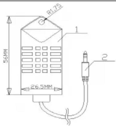
Model: C21
①Sensor probe ②Link plug
Product specifications/parameters
- To prevent the risk of carbon monoxide poisoning caused by improper installation, the product is equipped with a carbon monoxide alarm. When the carbon monoxide content in the enclosed space reaches 300 ppm, the LCD will prompt that CO exceeds the limit. When the content reaches 500 ppm, an alarm will be triggered and the machine will be shut down. The leakage point must be checked and repaired immediately before starting up for use.
- The carbon monoxide alarm device is equipped with a 2 m extension cable, which allows the probe to be installed in any position. It is not recommended to install it far away from the diesel heater or too close.
| Configuration Table - Model: C21 | |||||
| NO. | Function | Parameter | NO. | Function | Parameter |
| 1 | detection range | 0-990ppm | 7 | operation temperature | -20~50°C |
| 2 | Detecting overload | 2000ppm | 8 | Pressure Range | Standard atmospheric pressure ± 10% |
| 3 | repeatability | ±3% | 9 | Supply Voltage | 5.2V±0.5V |
| 4 | Response time (t90) | ≤30 s | 10 | consumption | <10.0mA |
| 5 | Resolution ratio | ≤5 ppm | 11 | Extension line | 2m |
| 6 | Zero drift (-20~40 °C) | ≤10 ppm | / | / | / |
Emergency response methods for controller alarms
- When the CO concentration within the detection range of the controller exceeds the limit, the switch will display a fault, the controller indicator light will flash, and the switch will automatically turn off the heater to avoid a continuous increase in CO concentration. Ventilation should be done immediately (if the environment is narrow and conditions permit, open the ventilation openings to create an open environment as much as possible. When the environment is closed or ventilation is inconvenient, it is recommended to increase ventilation equipment to accelerate air circulation and discharge CO gas), and personnel in the environment should evacuate immediately from the environment where the current CO concentration exceeds the standard.
- If the installation and usage environment is correct, it is recommended that personnel return to the working area and restart to check the CO concentration to see if it meets the standards.
- During the use of this product, it is important to maintain long-term air circulation and regularly check the concentration of carbon monoxide (international standard 50 mg/m³ ≈ 40 ppm) to ensure personal safety. If symptoms of carbon monoxide poisoning occur (such as dizziness, headache, nausea, etc.), one should immediately stay away from the source of pollution, breathe fresh air, and seek medical assistance.
- This product uses electrochemical sensors, which are easily affected by local temperature and humidity interference, resulting in a slight impact on detection accuracy. Therefore, to ensure your safety, please use this product objectively and reasonably. Its service life is affected by the environment, and the accuracy of the sensor should be regularly tested. If the error is too large, please replace the sensor.
- Even if a carbon monoxide alarm is installed, the room must be properly ventilated to prevent excessive CO emissions during sleep from not being dealt with in a timely manner.
Precautions and usage specifications
- Please do not open the product casing at will; prevent external forces from damaging the sensor.
- Products should avoid contact with organic solvents (including silicone rubber and other adhesives), coatings, chemicals, fuel oils, and high concentration gases.
- The product should not be completely encapsulated with resin materials during use and storage, nor should it be immersed in an anaerobic environment for a long time, otherwise it will damage the performance of the sensor and affect the detection accuracy of the product.
- This product cannot be used for a long time in environments containing corrosive gases.
- During installation and use, it is necessary to avoid vertical air intake from the front.
- The product air inlet must not be blocked or contaminated.
- This product needs to be installed firmly and not subjected to excessive vibration.
- Do not use if the shell is damaged or deformed.
- Prohibit long-term storage and use of this product in high concentration gases.
- Please replace the controller with a new one in a timely manner when it reaches its expected service life.
- Prohibit long-term storage and use of this product in high concentration gases.
- Please replace the controller with a new one in a timely manner when it reaches its expected service life.
Search and download the corresponding APP named "AirHeaterCC";
Alternatively, scan the QR code below with your phone and click on the corresponding system to download, then follow the steps below to connect and control the device with your phone.

Download AirHeaterCC
Get the best experience on your mobile device!
![graph TD A["1"] --> B["Download Android"] C["2"] --> D["Download on Google Play"] E["3"] --> F["Download on the App Store"]](/content/2026/04/734764/images/b60b36776b1665986bd531dba2d6d56bc4e793228880e99a447e7d5db94fcdb3.jpg)
【1】Option is for Android system 【2】Option is Google Download 【3】Option is IOS system
- Turn on the Bluetooth function of the phone, run the APP program

to enter the following interface:
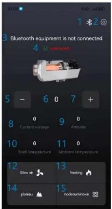
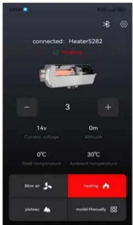
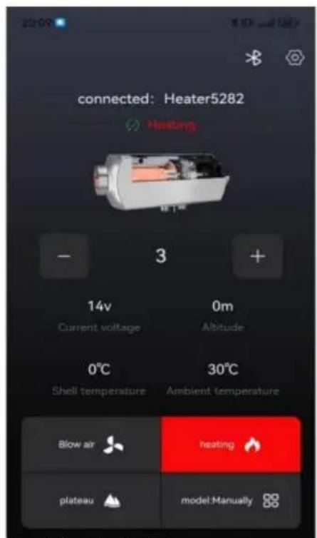
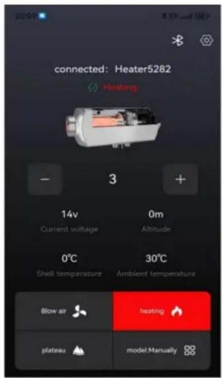
1, Bluetooth link, 2, Set buttons, 3, Bluetooth connection status, 4, Equipment status and fault description, 5, “-” key, 6, Display temperature/gear, 7, “+” key, 8, working voltage, 9, altitude, 10, Aluminum body temperature, 11, Ambient temperature, 12, Ventilation mode, 13, On/Off Heating button, 14, Plateau switch, 15, Mode switching switch.
2. Device connection via Bluetooth:
Press【Bluetooth link button】to enter the following page:
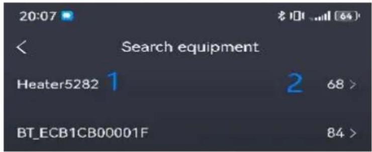
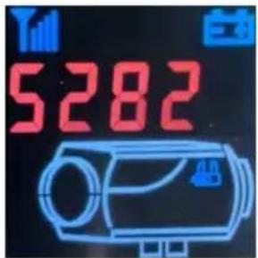
Select 1 as "Heater+Machine Code" (when the device is powered on, press the OK button on the switch panel to display it), (The machine code in the picture is for reference only, and the actual displayed machine code prevails.)
2 is the Bluetooth signal strength (as shown in signal 68 above, the smaller the value, the stronger the signal). If no device is found, check if there are other phones already connected to this device (each device can only be connected to one phone), or power on the device again and turn on the Bluetooth function of the phone before proceeding to the first step.
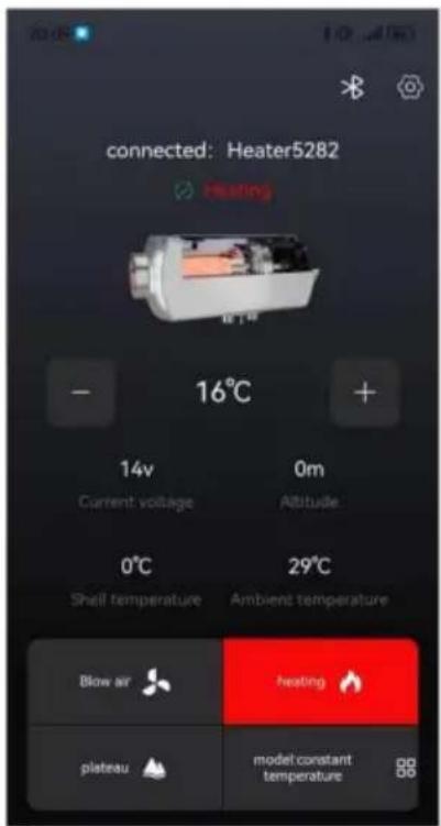
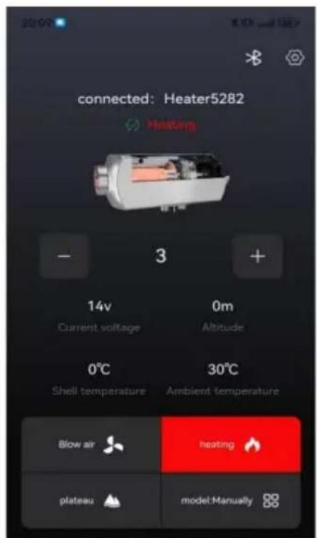
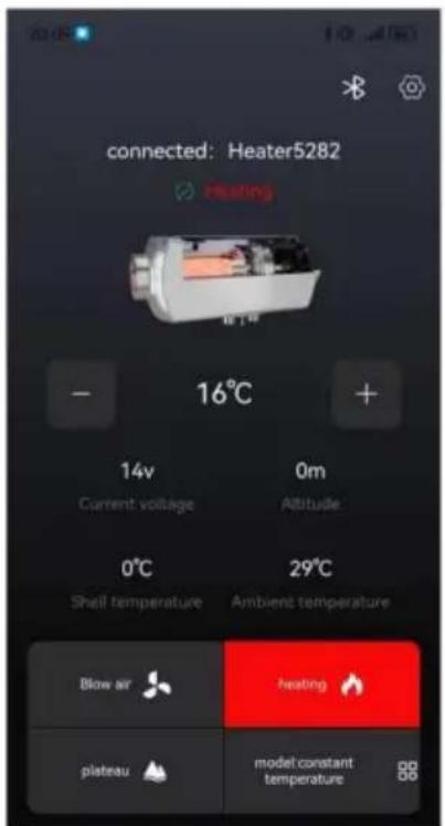
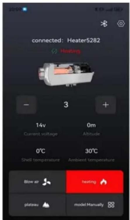
3. After successful linking, it will be displayed as shown in the following figure:
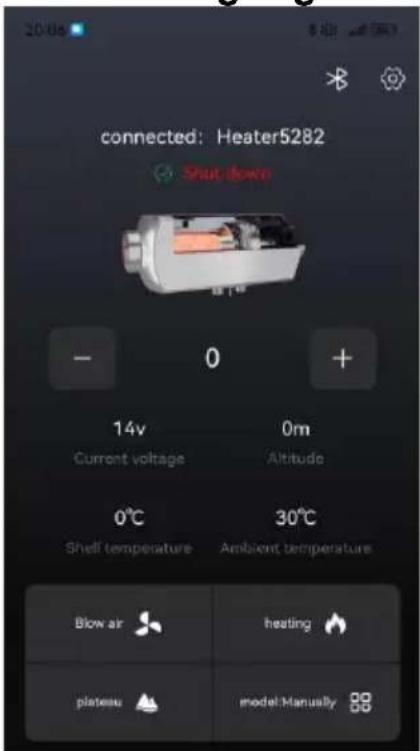
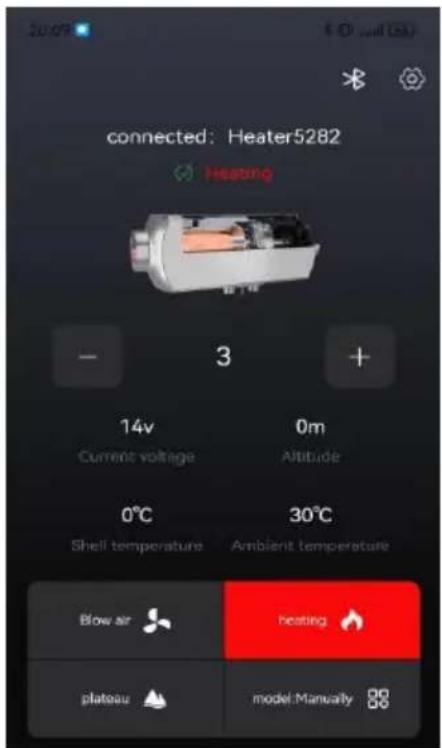
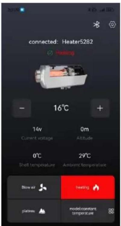
Shutdown status Power on status Power on status (manual mode) (temperature mode)
1) Power on operation
In shutdown mode, press the [heating button] to turn on the device.
heating and displays the "power on status" as shown in the above picture. Press the [+] button to increase the device setting, press the [-] button to decrease it. Press the [mode switch] button to toggle between manual and constant temperature mode (0-40 degrees), and press the [plateau button] to switch between plateau and plain mode.
In the power on state, press the [heating button], and the device enters the shutdown and cooling process, displaying "cooling in progress". The device can only be powered off after being cooled down and displaying the "shutdown" status as shown in the above picture.
In the power-on state, press the [heating button], and the device enters the shutdown and cooling process, displaying "cooling in progress". The device can only be powered off after it has cooled down and displays the "shutdown" status as shown in the above picture.
In the shutdown state, press the ventilation button to turn on/off ventilation, adjust the fan speed by pressing [+] or [-] .
In the shutdown state, press the ventilation button to turn on/off ventilation, and adjust the fan speed by pressing [+] or [-].
1) Unit settings include: Fahrenheit, Celsius, meters. 2) Language settings include: Chinese, English, Spanish, French, German, Italian, Polish, Dutch, Swedish, Russian. 3) The timing function includes: Monday to Sunday, and can be set to start time, close time, single time, and cycle mode. 4) Automatic start stop function: After being turned on, the machine works effectively in constant temperature mode (some devices do not have this function). 5) The user manual includes fault codes and troubleshooting methods.
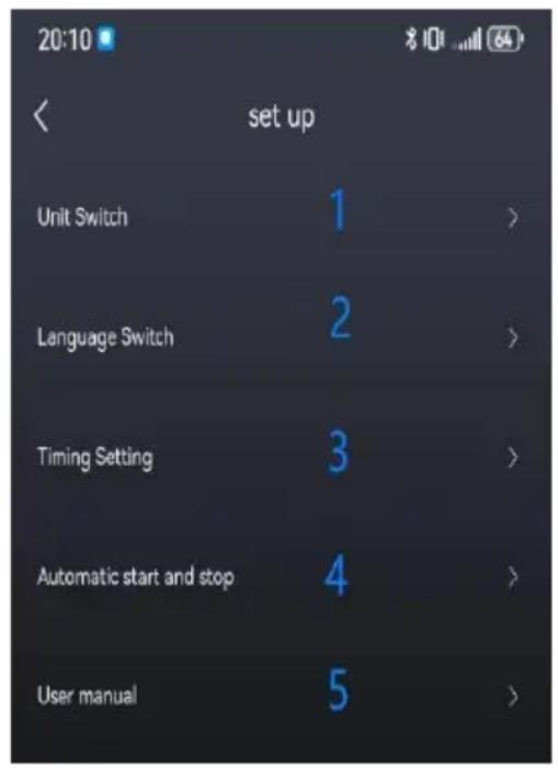
1) Unit settings include: Fahrenheit, Celsius, meters. 2) Language settings include: Chinese, English, Spanish, French, German, Italian, Polish, Dutch, Swedish, Russian. 3) The timing function includes: Monday to Sunday, and can be set to start time, close time, single time, and cycle mode. 4) Automatic start/stop function: After being turned on, the machine works effectively in constant temperature mode (some devices do not have this function). 5) The user manual includes fault codes and troubleshooting methods.
[1] On/Off button
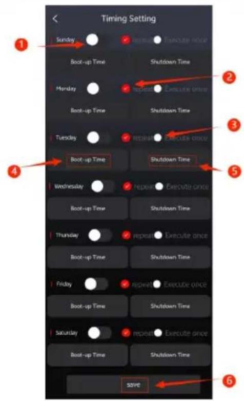
[2] loop execution
[3] Execute once
[4][5] Equipment on and off time
[6] Save.
Set the startup time in the shutdown state, as shown in the left figure.
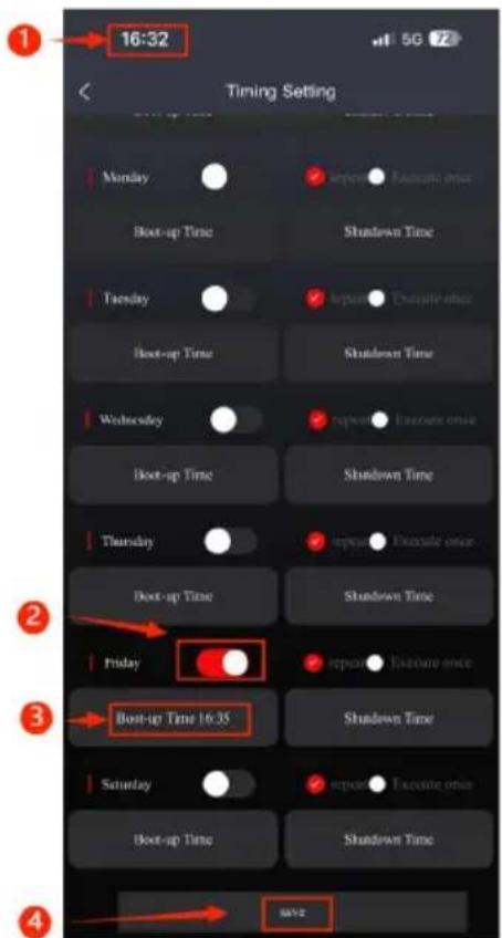
Current time
Open timer
Set the shutdown time in the power on state, as shown in left figure.
- Button on
- Select the device startup temperature (3-10 °C)
- Select device shutdown temperature (3-10 °C) 4. Save 5. (A-Automatic) Working in automatic power on/off mode, the required temperature can be adjusted by pressing the [+] and [-] buttons (0-4).
- The surrounding temperature of the equipment is the reference temperature.
- Automatic start/stop is only effective when working in constant temperature mode. The above diagram shows: the temperature to 37 °C, turn on
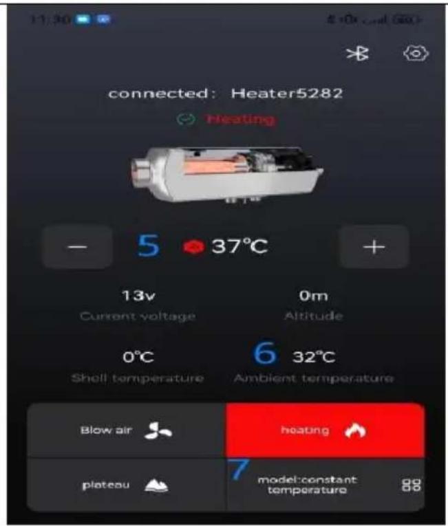
temperature to 5 °C, turn off the temperature to 5 °C, stop heating with the surrounding temperature of the equipment is 42°C, and turn on heat when the surrounding temperature of the equipment is 32°C (the timed off function is also effective).
Manufacturer: Shanghai Muxin Muye Youxiangongsi
Address: Shuangchenglu 803nong11hao1602A-1609shi, Baoshanqu, Shanghai 200000 CN.
Imported to AUS: SIHAO PTY LTD. 1 ROKEVA STREET EASTWOOD NSW 2122 Australia
Imported to USA: Sanven Technology Ltd. Suite 250, 9166 Anaheim Place, Rancho Cucamonga, CA 91730
| UK | REP |
YH CONSULTING LIMITED.
C/O YH Consulting Limited Office 147, Centurion House, London Road, Staines-upon-Thames, Surrey, TW18 4AX
| EC | REP |
E-CrossStu GmbH
Mainzer Landstr.69,
60329 Frankfurt am Main.
VEVOR®
TOUGH TOOLS, HALF PRICE
Technical Support and E-Warranty Certificate
www.vevor.com/support
VEVOR®
TOUGH TOOLS, HALF PRICE
NEED HELP? CONTACT US!
Installing insulation sleeves on exhaust pipes can effectively reduce surface temperature and prevent fire hazards caused by improper installation.

PRODUCT INFORMATION
Model: CY-5002


Get the best experience on your mobile device!
Download Android
2
Download on Google Play
3
Download on the App Store
1, Bluetooth connection, 2, buttons
Off state
C/O YH Consulting Limited Bureau 147,
Centurion House, London Road, Staines-upon-
Thames, Surrey, TW18 4AX
| REPRÉSENTANT | DE LA CE |
E-CrossStu GmbH
Mainzer Landstr.69,
MODEL: CY-5004 MODEL: CY-5002
Installing insulation sleeves on exhaust pipes can effectively reduce surface temperature and prevent fire hazards caused by improper installation.


PRODUCT INFORMATION
Model: CY-5002


Get the best experience on your mobile device!
1
Download Android
2
Download on Google Play
3
Download on the App Store
- Bluetooth connection, 2.
Setting buttons, 3. Bluetooth
shutdown status
C/O YH Consulting Limited Office 147,
Centurion House, London Road, Staines-upon-
Thames, Surrey, TW18 4AX
| Vertreter der EG |
E-CrossStu GmbH
Mainzer Landstr.69,
60329 Frankfurt am Main.
VEVOR®
TOUGH TOOLS, HALF PRICE
www.vevor.com/support
VEVOR®
TOUGH TOOLS, HALF PRICE
Installing insulation sleeves on exhaust pipes can effectively reduce surface temperature and prevent fire hazards caused by improper installation.



Get the best experience on your mobile device!
1
Download Android
2
Download on Google Play
3
Download on the App Store
1, Connection
Bluetooth, 2, Buttons
1 On/Off button 2
Loop execution 3
Imported into AUS: SIHAO PTY LTD. 1 ROKEVA STREET EASTWOOD NSW 2122 Australia
Imported into USA: Sanven Technology Ltd. Suite 250, 9166 Anaheim Place, Rancho Cucamonga, CA 91730
YH CONSULTING LIMITED.
C/O YH Consulting Limited Office 147,
Centurion House, London Road, Staines-upon-
Thames, Surrey, TW18 4AX
electronics www.vevor.com/support
VEVOR®
TOUGH TOOLS, HALF PRICE
Installing insulation sleeves on exhaust pipes can effectively reduce surface temperature and prevent fire hazards caused by improper installation.

- WARNING: Toxic material




Power off status
Centurion House, London Road, Staines-upon-
Thames, Surrey, TW18 4AX
| REPRESENTANTE CE |
E-CrossStu GmbH
Mainzer Landstr.69,
www.vevor.com/support
VEVOR®
TOUGH TOOLS, HALF PRICE
NEED HELP? CONTACT US!
Installing insulation sleeves on exhaust pipes can effectively reduce surface temperature and prevent fire hazards caused by improper installation.



manual)
C/O YH Consulting Limited Office 147,
Centurion House, London Road, Staines-upon-
Thames, Surrey, TW18 4AX
| Przedstawiciel UE |
E-CrossStu GmbH
Mainzer Landstr.69,
60329 Frankfurt nad Menem.
VEVOR®
TOUGH TOOLS, HALF PRICE
HULP NODIG? NEEM CONTACT MET ONS OP!
Installing insulation sleeves on exhaust pipes can effectively reduce surface temperature and prevent fire hazards caused by improper installation.

18. WARNING: Toxic material



Option 2 is Google Download
Option 3 is iOS system
Download AirHeaterCC
Get the best experience on your mobile device!
1
Download Android
2
Download on Google Play
3
Download on the App Store
1, Bluetooth connection, 2,
Setting buttons, 3, Bluetooth
plate switch, 15,
mode switch.
2. Device connection via Bluetooth:
Off status
On status (manual mode)
1 On/off button 2
C/O YH Consulting Limited Office 147, Centurion House, London Road, Staines-upon-Thames, Surrey, TW18 4AX
C/O YH Consulting Limited, Office 147, Centurion House, London Road, Staines-upon-Thames, Surrey, TW18 4AX
E-CrossStu GmbH
Mainzer Landstr.69,
60329 Frankfurt am Main.
VEVOR®
TOUGH TOOLS, HALF PRICE
www.vevor.com/support
VEVOR®
TOUGH TOOLS, HALF PRICE
NEED HELP? CONTACT US!
Installing insulation sleeves on exhaust pipes can effectively reduce surface temperature and prevent fire hazards caused by improper installation.

18. WARNING: Toxic material



Panel operation instructions
Get the best experience on your mobile device!
![graph TD A["1 Download Android"] --> B["2 Download on Google Play"] B --> C["3 Download on the App Store"]](/content/2026/04/734764/images/578e69e5c327ac01eecc0a6b42246a74410637b2a1a9b214ece5b8e970713ccd.jpg)
- Turn on the phone's Bluetooth function, run the APP program

1, Bluetooth link
Power off status
- Knapp på
- Select the device's start temperature (3-10 y)
- Select the device's shutdown temperature (3-10 y)
4. Save
C/O YH Consulting Limited Office 147,
Centurion House, London Road, Staines-upon-
Thames, Surrey, TW18 4AX
| EC | REP |
E-CrossStu GmbH
Mainzer Landstr.69,
60329 Frankfurt am Main.
VEVOR®
TOUGH TOOLS, HALF PRICE
www.vevor.com/support

- DIESEL HEATER
- VEVOR®
- NEED HELP? CONTACT US
- SAFETY INSTRUCTION
- WARNING
- WARNING: FLAMMABLE MATERIAL
- WARNING: TOXIC MATERIAL
- SAVE THESE INSTRUCTIONS
- FCC INFORMATION
- PRODUCT FUNCTION
- INTERNAL STRUCTURE
- INSTALLATION POSITION
- THE INSTALLATION OF THE MACHINE REQUIRES PROFESSIONAL PERSONNEL TO INSTALL IT
- MODEL
- PACKING LIST
- NO SIDE INSTALLATION
- PRECAUTIONS FOR THE POWER SUPPLY
- PRODUCT INFORMATION
- CY
- PANEL OPERATION INSTRUCTIONS
- THE CONTROL PANEL IS SHOWN IN THE FOLLOWING FIGURE
- USAGE OPERATION
- ON/OFF OPERATION
- POWER ON OPERATION
- SHUTDOWN OPERATION
- MANUAL MODE OPERATION
- AUTOMATIC MODE OPERATION
- SWITCHING TO DISPLAY DATA ON STARTUP
- TEMPERATURE UNIT SWITCHING
- MANUAL OILING OPERATION
- PLATEAU MODE OPERATION
- TIME ON/OFF TIME OPERATION
- CLOCK SYNCHRONIZATION OPERATION
- REMOTE CONTROL MATCHING OPERATION
- HFR
- FAULT ALARM
- THIS PANEL SUPPORTS MOBILE APPS TO CONTROL THIS DEVICE THROUGH BLUETOOTH
- INSTRUCTIONS FOR USE
- CO CONTROLLER OPERATION INSTRUCTIONS
- PRODUCT SPECIFICATIONS/PARAMETERS
- EMERGENCY RESPONSE METHODS FOR CONTROLLER ALARMS
- PRECAUTIONS AND USAGE SPECIFICATIONS
- DOWNLOAD AIRHEATERCC
- DEVICE CONNECTION VIA BLUETOOTH
- AFTER SUCCESSFUL LINKING, IT WILL BE DISPLAYED AS SHOWN IN THE FOLLOWING FIGURE
- IN THE POWER ON STATE, PRESS THE [HEATING BUTTON], AND THE DEVICE ENTERS THE SHUTDOWN AND COOLING PROCESS, DISPLAYING "COOLING IN PROGRESS". THE DEVICE CAN ONLY BE POWERED OFF AFTER BEING COOLED DOWN AND DISPLAYING THE "SHUTDOWN" STATUS AS SHOWN IN THE ABOVE PICTURE
- IN THE SHUTDOWN STATE, PRESS THE VENTILATION BUTTON TO TURN ON/OFF VENTILATION, ADJUST THE FAN SPEED BY PRESSING [+] OR [-]
- UNIT SETTINGS INCLUDE: FAHRENHEIT, CELSIUS, METERS. 2) LANGUAGE SETTINGS INCLUDE: CHINESE, ENGLISH, SPANISH, FRENCH, GERMAN, ITALIAN, POLISH, DUTCH, SWEDISH, RUSSIAN. 3) THE TIMING FUNCTION INCLUDES: MONDAY TO SUNDAY, AND CAN BE SET TO START TIME, CLOSE TIME, SINGLE TIME, AND CYCLE MODE. 4) AUTOMATIC START STOP FUNCTION: AFTER BEING TURNED ON, THE MACHINE WORKS EFFECTIVELY IN CONSTANT TEMPERATURE MODE (SOME DEVICES DO NOT HAVE THIS FUNCTION). 5) THE USER MANUAL INCLUDES FAULT CODES AND TROUBLESHOOTING METHODS
- [1] ON/OFF BUTTON
- TOUGH TOOLS, HALF PRICE
- HULP NODIG? NEEM CONTACT MET ONS OP
- OFF STATUS
Brand : Vevor
Model : CY5002
Category : Heating