CY-29 - Heating Vevor - Free user manual and instructions
Find the device manual for free CY-29 Vevor in PDF.

User questions about CY-29 Vevor
0 question about this device. Answer the ones you know or ask your own.
Ask a new question about this device
Download the instructions for your Heating in PDF format for free! Find your manual CY-29 - Vevor and take your electronic device back in hand. On this page are published all the documents necessary for the use of your device. CY-29 by Vevor.
USER MANUAL CY-29 Vevor
Technical Support and E-Warranty Certificate www.vevor.com/support
DIESEL HEATER
We continue to be committed to provide you tools with competitive price. "Save Half", "Half Price" or any other similar expressions used by us only represents an estimate of savings you might benefit from buying certain tools with us compared to the major top brands and doses not necessarily mean to cover all categories of tools offered by us. You are kindly reminded to verify carefully when you are placing an order with us if you are actually saving half in comparison with the top major brands.
VEVOR®
TOUGH TOOLS, HALF PRICE
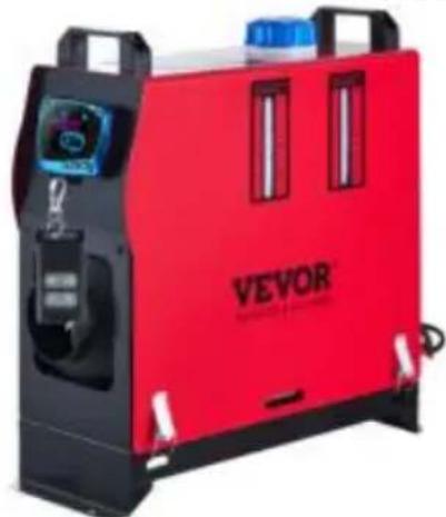
DIESEL HEATER
MODEL:CY-30 MODEL:CY-28
natural_image
Red VEVOR industrial machine with control panel and buttons (no visible text or symbols on main body)
natural_image
Red VEVOR industrial gas stove with black casing and white handle (no visible text or symbols on body)MODEL:CY-29 MODEL:CY-32
natural_image
Orange VEVOR portable industrial lamp with black handle and control panel (no visible text or symbols on device body)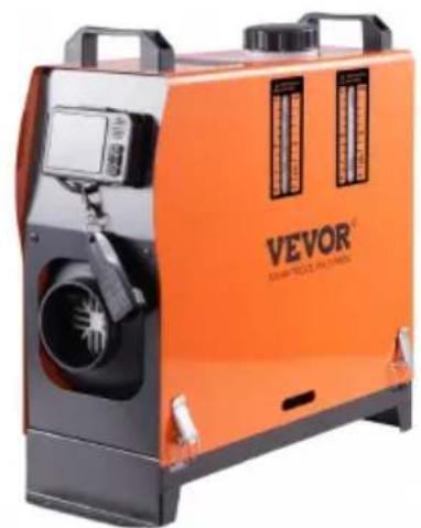
natural_image
Orange Vevor industrial machine with camera and fan components (no visible text or symbols)NEED HELP? CONTACT US!
Have product questions? Need technical support? Please feel fr contact us:
Technical Support and E-Warranty Certificate www.vevor.com/support
This is the original instruction, please read all manual instruction carefully before operating. VEVOR reserves a clear interpretation user manual. The appearance of the product shall be subject to product you received. Please forgive us that we won't inform you there are any technology or software updates on our product.
| Symbol | Symbol Description |
 | Warning: To reduce the risk of injury, the user must read instructions manual carefully. |
 | This symbol, placed before a safety comment, indicates a k precaution, warning, or danger. Ignoring this warning may le an accident. To reduce the risk of injury, fire, or electrocuti please always follow the recommendations shown below. |
 | CORRECT DISPOSAL:This product is subject to the provisio European Directive 2012/ 19/EC. The symbol showing a wh bin crossed through indicates that the product requires sepa refuse collection in the European Union. This applies to the and all accessories marked with this symbol. Products mark such may not be discarded with normal domestic waste, bu be taken to a collection point for recycling electrical and el devices. |
 | Warning: Toxic material. Take care to avoid coming into co with toxic material. |
 | Warning: Flammable material. Take care to avoid causing a igniting flammable material. |

Responsibility requirements:
·Vevor is not responsible for any issues arising from non-compliance with these instructions and the precautions included in these instructions.
Similarly, the company shall not be held responsible for any issues arising from repairs conducted without professional maintenance or the use of original spare parts/accessories. This type of maintenance will result in the invalidation of the heater's type approval and its ECE type approval certifi
SAFETY INSTRUCTION

WARNING:

Read all safety warnings, instructions, illustrations, and specifications provided with this diesel heater. Failure to follow all instructions listed below may result in electric shock, fire, and /or serious injury.
-
The following measures shall not be adopted
-
Change the important component of the diesel heater.
- Make use of spare parts from other manufacturers without permission.
-
Disobey the instructions and the guidelines during installation or operation.
-
Only allow using original attachments and spare parts during installation and maintenance.
- The heaters shall not be used in places where they may form flammable or dust, for example:
- Fuel depot
- Carbon storehouse
- Timber storehouse
• Granary and similar sites
• Diesel/petrol station
And keep away from fuel tanks, compression tanks, fire extinguishers, clothes, other flammable objects.
- Do not use cigarette lighter for startup.
- Do not use the heater in closed and/or unventilated places.
- The heaters shall be turned off when filling fuel.
- Do not cut off the electric power during operation.
- If there is a fuel leak or discharge from the fuel system of heaters, plea contact VEVOR for repair.
- Place the exhaust outlet outside to prevent any penetration of exhaust fum
- In the process of work, it is forbidden to cut off the electric power direct stop the heater from working.
- Seal all gaps between the mounting plate and the car body.
-
The machine will stop heating after over-temperature protection. Please do not power off. After the machine is naturally cooled and turned off, it can be restarted.
-
After turning off the machine, please do not immediately disconnect the p supply. It takes 3-5 minutes for the machine to stop working completely.
-
After starting the machine for 3-5 minutes, it will work normally and heat. Please wait patiently.
-
When the heater is just started, the current is relatively high, so an ada with a voltage of 12V and a current of 15A or greater is required for the p supply.
-
This appliance can be used by children aged 8 years and above and p with reduced physical, sensory or mental capabilities or lack of experience and knowledge if they have been given supervision or instruction concerning use of the appliance in a safe way and understand the hazards involved. Children are not play with the appliance. Cleaning and user maintenance shall not be done children without supervision.
17. WARNING: Flammable material

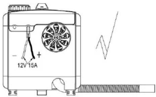
During installation/use, service, and disposal of the appliance, please pay attention to the fact that there should be no flammable substrate around the exhaust pipe. The temperature of the exhaust pipe is visible high when it is working. Take care to avoid causing a fire by igniting flamm material.
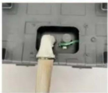
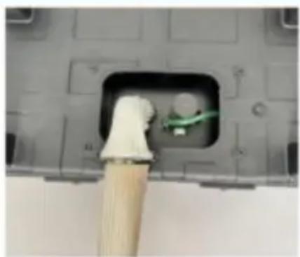
Please strictly follow the following methods to correctly install insulation sleeve on the exhaust pipe and reduce surface temperature:

Installing insulation sleeves on exhaust pipes can effectively reduce surface temperature and prevent fire hazards caused by improper installation.

natural_image
Close-up of a mechanical component with a textured cable inserted into a black opening, showing internal wiring (no text or symbols visible)
natural_image
Solid orange right-pointing arrow (no text or symbols)
natural_image
Close-up of a car's side panel with a woven cable and wooden floor, no visible text or symbols18. WARNING: Toxic material

During installation/use, service, and disposal of the appliance, please install the appliance with space for ventilation to prevent carbon monoxide poisoning. Place the exhaust outlet outdoors to prevent exhaust gas from seeping in.
19. The fuel tank supplying fuel to the device shall meet the following requirements:
a) If there is a leak, the fuel should be discharged to the ground and must come into contact with the hot parts of the vehicle or load
b) The fuel tank containing gasoline should be equipped with an effective flar arrester at the fuel filling port, or a sealing device should be used to complete seal the opening
- Space that cannot be used for heating and transporting dangerous goods.
SAVE THESE INSTRUCTIONS
FCC INFORMATION
CAUTION: Changes or modifications not expressly approved by the party responsible for compliance could void the user's authority to operate the equipment!
This device complies with Part 15 of the FCC Rules. Operation is subject to following two conditions:
1) This product may cause harmful interference.
2) This product must accept any interference received, including interference that may cause undesired operation.
WARNING: Changes or modifications to this product are not expressly approved by the party. Responsibility for compliance could void the user's authority to operate the product.
Note: This product has been tested and found to comply with the limits for Class B digital device pursuant to Part 15 of the FCC Rules, These limits are designed to provide reasonable protection against harmful interference in a residential installation.
This product generates, uses and can radiate radio frequency energy, and if installed and used in accordance with the instructions, it may cause harmful interference to radio communications. However, there is no guarantee that
interference will not occur in a particular installation. If this product does cause harmful interference to radio or television reception, which can be determined turning the product off and on, the user is encouraged to try to correct the interference by one or more of the following measures.
- Reorient or relocate the receiving antenna.
- Increase the distance between the product and the receiver.
- Connect the product to an outlet on a circuit different from that to which receiver is connected.
- Consult the dealer or an experienced radio/TV technician for assistance.
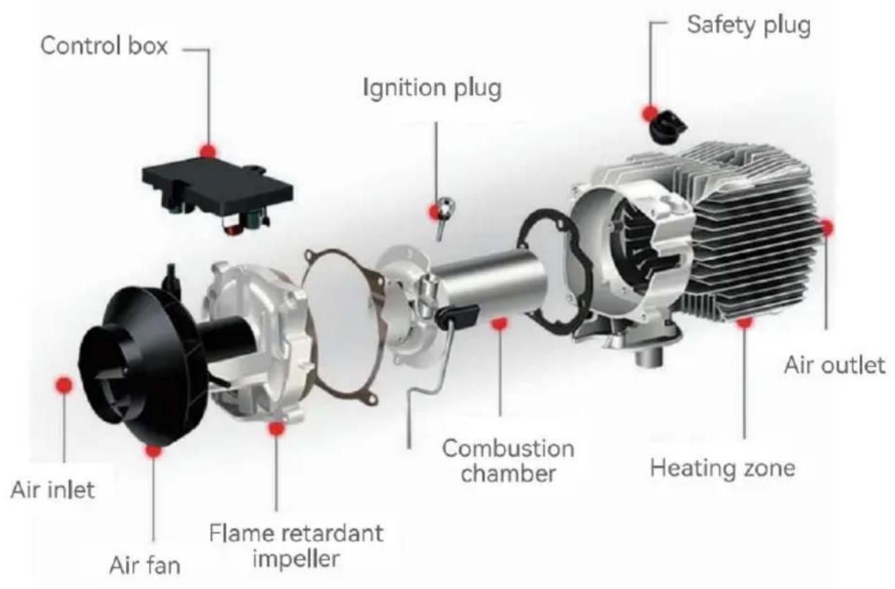
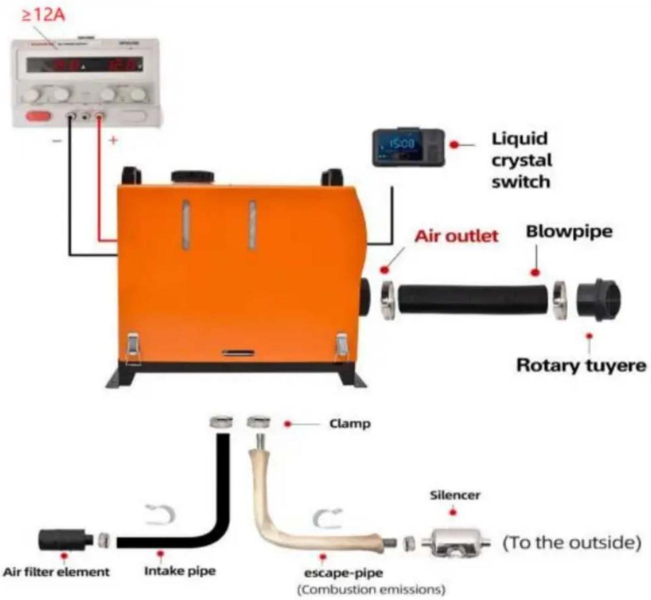
INTERNAL STRUCTURE
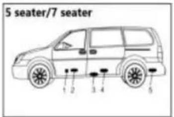
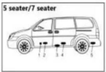
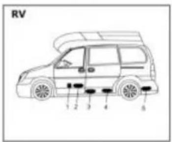
INSTALLATION POSITION
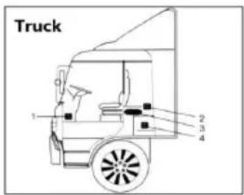
- On the co-driver's legroom.
- On the back wall of the cab.
- Driver's seat backrest.
- Within the tool box.
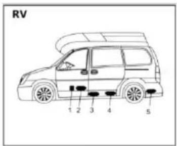
- In front of the passenger seat.
- Between the driver seat and passenger seat
- 3 & 4 under the container.
- In the trunk.

The heater is mainly installed in the passer room or baggage room of the vehicle. If it be installed, fix the heater under the unders of the vehicle, but beware of splashing.

- Inside the driver's seat.
- On the back wall of the ca
- Inside the protection box.

It is recommended to use high-grade diesel fuel when refueling the diesel heater. Other types of fuels, such as kerosene, vegetable oil, gasoline, waste oil, etc., cannot be used. Otherwise, the heater may unpleasant odor and malfunction during operation.
have an

The installation of the machine requires professional personnel.
MODEL
| Product Model | CY-30CY-32 | CY-28CY-29 |
| Appearance |  | 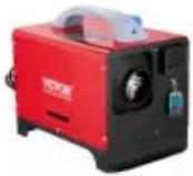 |
| Heating medium | Air | Air |
| Fuel | Diesel | Diesel |
| Ratings | DC12-24V/40W | DC12V/40W |
PACKING LIST
| Model | CY-30 | CY-28 | CY-29CY-32 | |
| Liquid crystal switch |  | 1 | / | / |
| Liquid crystal switch |  | / | 1 | 1 |
| Remote control |  | 1 | / | / |
| Remote control |  | / | / | 1 |
| Remote control |  | / | 1 | / |
| Intake pipe |  | 1 | 1 | 1 |
| Exhaust pipe | 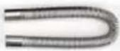 | 1 | 1 | 1 |
| Blowpipe |  | 1 | 1 | 1 |
| Silencer | 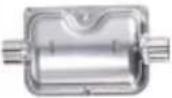 | 1 | 1 | 1 |
| Blowpipe clamp |  | 4 | 4 | 4 |
| Air outlet pipe clamp |  | 2 | 2 | 2 |
| Clamp | [ST24] | 2 | 2 | 2 |
| Pipe clip |  | 2 | 2 | 2 |
| Air filter element |  | 1 | 1 | 1 |
| The screw for the lock catch |  | 6 | 6 | 6 |
| Rotary tuyere |  | 1 | 1 | 1 |
| User Manual |  | 1 | 1 | 1 |
| MufflerAccessories | 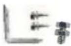 | 1 | 1 | 1 |
| Protective sleeve |  | 1 | 1 | 1 |
INSTALLATION OF FUEL TANK AND NOZZLE
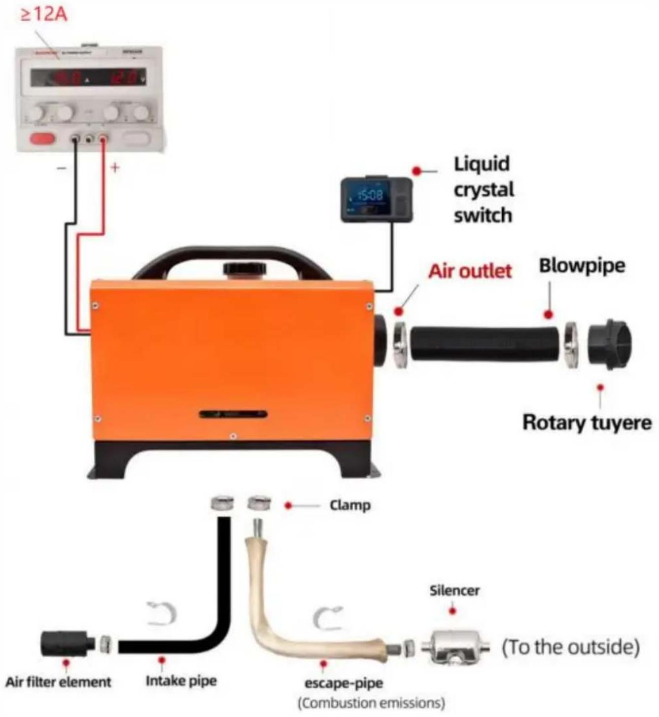
Refer to the installation diagram below and carefully read the precautions when installing or using:
1. No Side Installation:
※ Side installation of the diesel heater will result in oil leaks inside the ma after a period of use, producing a large amount of smoke and carbon mono poisoning. During installation, leave a space of 10cm around the heater to er good ventilation.
※ If installing the heater inside a building:
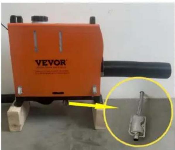
① With the heater placed indoors: Make holes in the wall for the exhaust pipe be placed outdoors. Pay attention to insulating the exhaust pipe as it can be very hot and could cause a fire.
② With the heater placed outdoors: It's necessary to extend the exhaust pipe avoid the exhaust from being sucked into the building from the back fan pos of the heater, which can lead to carbon monoxide poisoning.
※ If installing the heater inside a building: ① With the heater placed indoors:
Make holes in the wall for the exhaust pipe to be placed outdoors. Pay attention to insulating the exhaust pipe as it can become very hot and cause a fire. ② With the heater placed outdoors: It's necessary to extend exhaust pipe to avoid the exhaust from being sucked into the building from the back fan position of the heater, which can lead to carbon monoxide poisoning.
natural_image
Orange VEVOR industrial machine with a close-up inset showing a mechanical component (no visible text or symbols)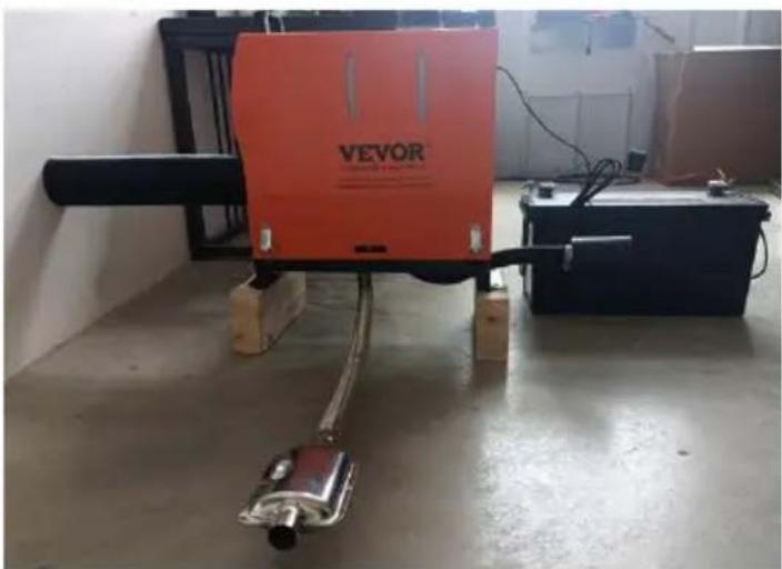
natural_image
Industrial machine labeled 'VEVOR' in a workshop setting, no visible text or symbols on the device itself.Indoor installation Outdoor installation diagram
(wooden floor exhaust pipes need to be protected)
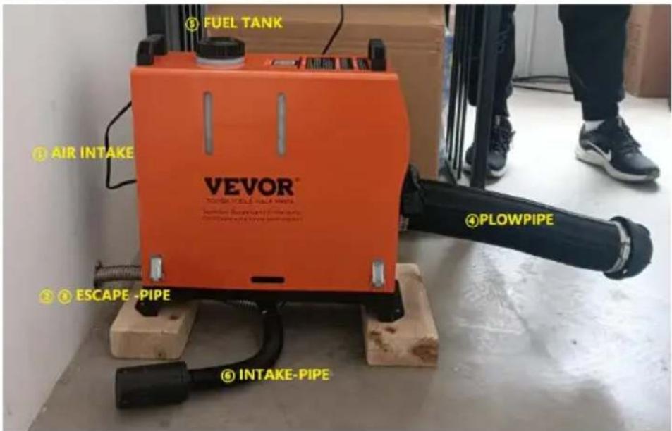
※ Installation position and precautions
①Reserve a 4-inch gap between the air inlet for unobstructed air intake
② Keep the bottom exhaust pipe at a distance of 2 inches from the ground and prevent fires if the exhaust pipe temperature is high;
③ Do not bend the exhaust pipe excessively, as it may cause uneven flow;
④ The air outlet duct shouldn't be too long and multiple bends can cause not to be discharged, resulting in a high-temperature fault;
⑤ When refueling the fuel tank, do not flow onto the casing, as it will along the inside of the machine to the exhaust pipe position, causing sm Fill the oil level close to the fuel tank port;
⑥Do not block the intake pipe, which will cause insufficient oxygen, and heater will not work;
Installation location precautions - schematic diagram
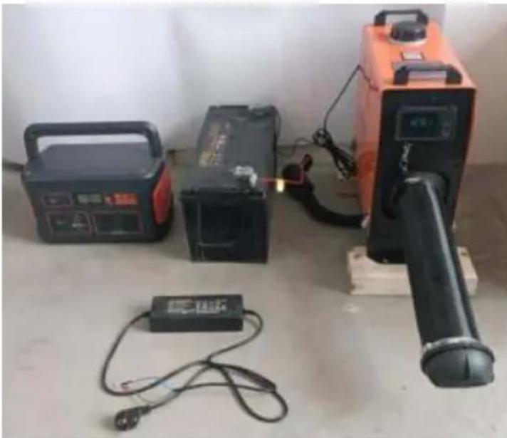
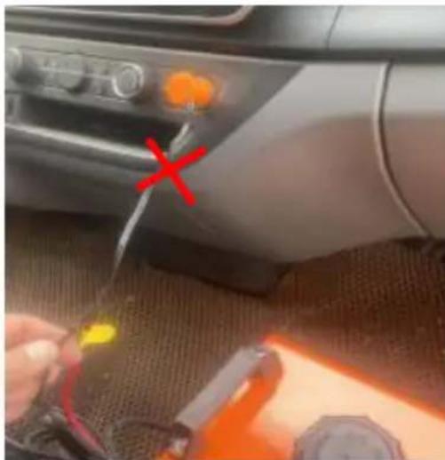
2. Precautions for the power supply:
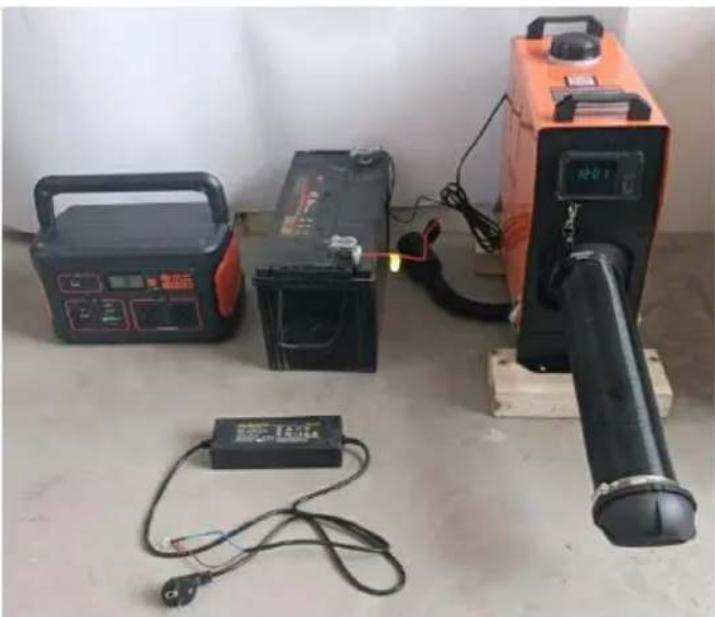
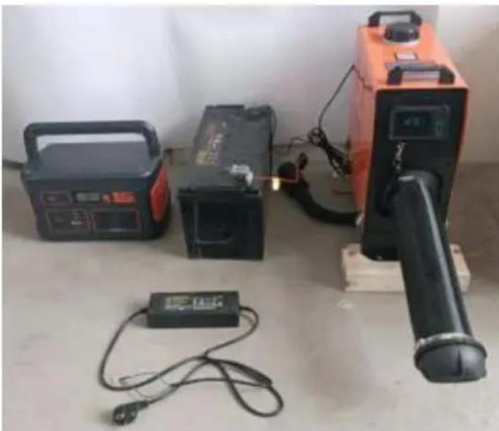
※ The power supply for the diesel heater must meet the following requirement: Voltage: 12V; Current: ≥20A, either from a direct power source or a battery. powered by a battery, do not charge the battery while using the heater as insufficient current can cause malfunction. Ensure a firm and secure connection to the battery. Using clamps for fixation can result in poor contact.
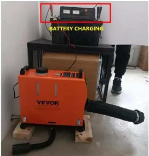
- Do not use the heater when charging the battery
- The current is low and it does not work
natural_image
Exterior view of a portable electronic device with battery, switch, and power supply unit (no visible text or symbols)Suggest using energy storage (batteries) or adapters for the power supply
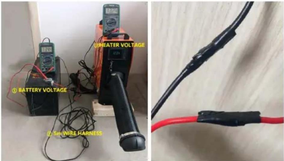
※When extending the power cable for the diesel heater, the wire diameter s be >2mm². Using a thin wire can lead to insufficient current, causing the heating to work. After connecting, use insulating tape to protect the connection and prevent electrical leakage, which might lead to fires.
※Do not disconnect the power when the diesel heater is operating at high temperatures. This can cause backfire due to high temperatures. Repeatedly doing so can cause permanent damage. Solutions:
- If power is cut and you immediately turn on the heater: Wait until the intense heat of the heater has completely dissipated before turning it on for normal operation.
- If the heater is turned on a long time after a power cut: Incomplete comb inside may produce a large amount of smoke. Wait for the smoke to clear, the heater will automatically start and operate normally.
natural_image
Close-up of a mechanical device with wiring and connectors, no visible text or symbolsAbnormal power outage and smoke coming from the intake pipe
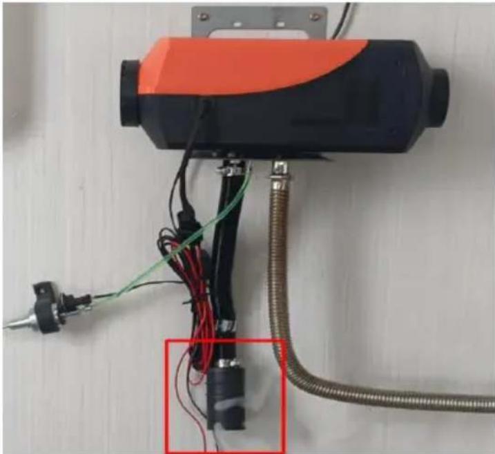
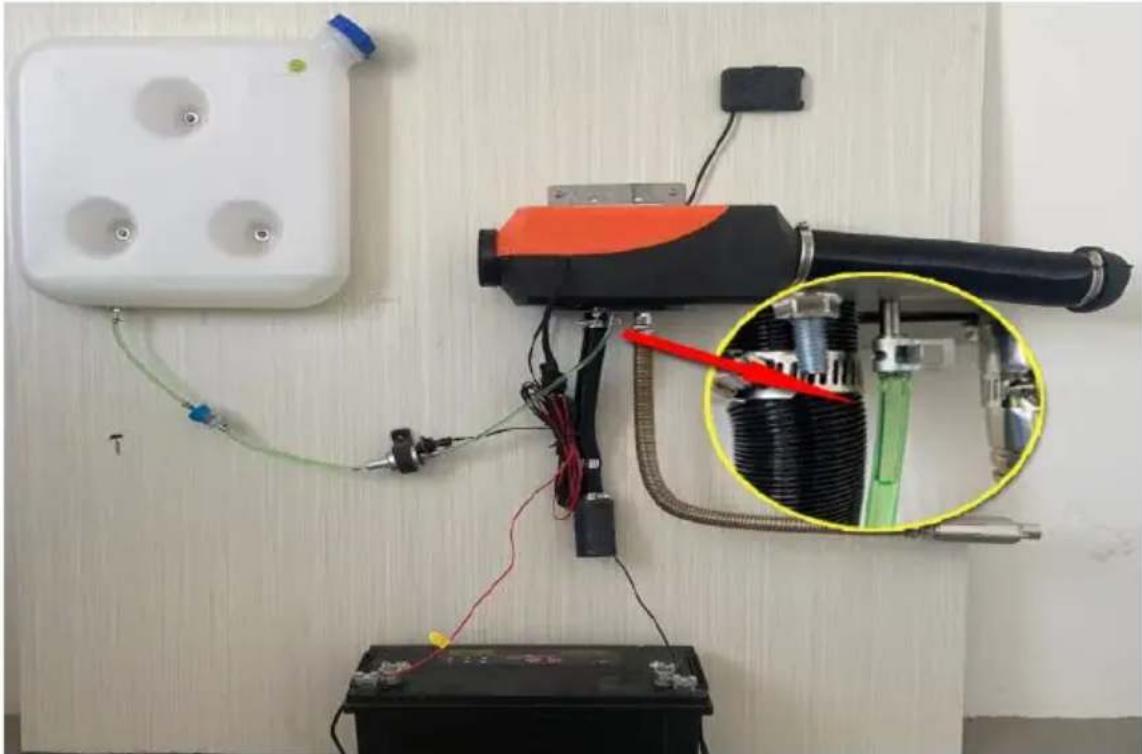
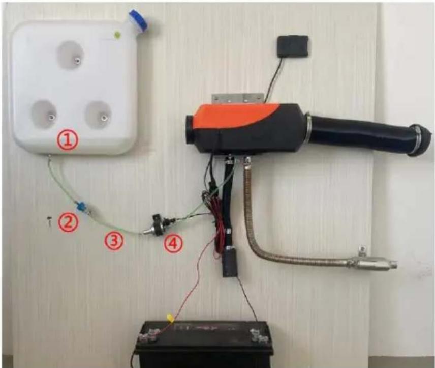
3. After the heater is installed, you need to manually pump oil before turning it on:
※ The fuel line of the heater is long. Before initially starting the heater, ma pump oil up to the fuel inlet. Otherwise, when turned on, the heater will take 30 minutes to detect the fuel (during this time, it will continuously check for fuel signal). Once the ignition plug detects the fuel, it will ignite and heat. R the LCD switch user guide for detailed instructions on manual fuel pumping.
natural_image
Electrical wiring setup with a battery, transformer, and mounted device on a wall (no visible text or symbols)The first work requires manual pumping of oil to the position shown in tl diagram and starting up
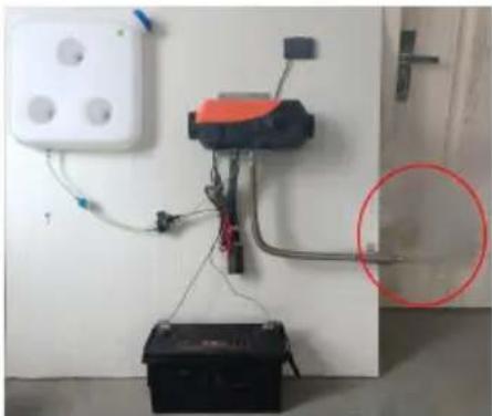
※ When manually pumping fuel, pump just up to the fuel inlet. Over-pumpin result in the heater emitting a large amount of white smoke. Quick solution: Detach the fuel line, turn on the heater, let it stop naturally, and restart it. this process until no smoke is emitted. Reconnect the fuel line and turn the on to resume normal operation.
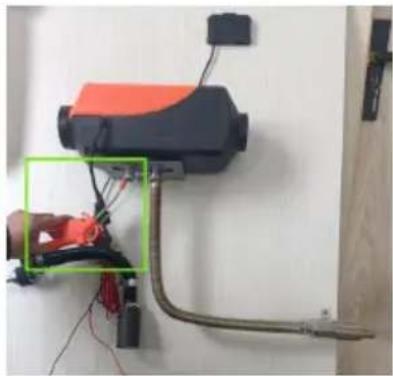
※ After starting the diesel heater, continuously blow air into the air pipe using air pump or a high-speed blower until the heater starts and functions normally white smoke appears after operating for a period: This indicates that the atomizing net is clogged. Remove the ignition plug, take out the atomizing net clean its surface or replace it with a new one.
natural_image
Interior view of a room with a battery, wiring, and a mounted device (no visible text or symbols)Excessive pump oil produces white smoke
natural_image
Close-up of a wall-mounted electrical device with wiring and connectors, no visible text or symbolsBlow the air gun towards the intake pipe to assist combustion

natural_image
Close-up of a mounted electronic device with wiring and connectors, no visible text or symbolsRemove the oil pipe and insert it after it is normal
※ Oil circuit fault, such as E4/E8/E10 fault code, indicates that there no oil heater or heat in the machine. The following steps need to be followed for troubleshooting:
①Is there a shortage of oil in the fuel tank?
② Whether the oil filter is blocked;
③ Is there any bending of the oil pipe that cannot accommodate oil
④ Is the oil pump not working?
Inspection diagram
※ Maintenance: If black smoke is found during the operation of the heater for a period of time or in the second year of use, it indicates there is carbon accumulation in the combustion chamber that needs be cleaned in a timely manner. The operation method is as follows:
①Remove the outer shell;
②Remove the motherboard bolts with an Allen wrench;
③ Remove the four bolts of the fan assembly with an Allen wrench;
④Remove the four bolts of the combustion chamber with an Allen wrench
⑤ Remove the combustion chamber and replace it with a new recovery heater;
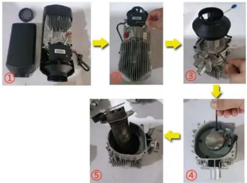
flowchart
graph TD
    A["① Fan Component"] --> B["⑦ Heat Fan"]
    B --> C["③ Cooling System"]
    C --> D["⑤ Motor"]
    D --> E["④ Motor"]
Schematic diagram of combustion chamber replacement
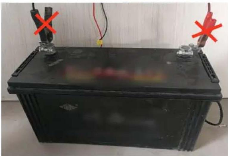
Cautions for Diesel Heater Power Supply:
※ Diesel heater power supply requirements: Voltage: 12V; Current: ≥ 20A Use either a power source or a battery. ( Avoid charging the battery v supplying power to the heater, as low current may lead to malfunctions. Ensure a secure battery connection without using clamps to prevent poor contact. Using the car's cigarette lighter as a power source is not recommended due to insufficient current.)
natural_image
Black rectangular battery with red X marks on top and side, placed on a white surface (no text or symbols visible)Fixing the battery clamp can easily cause poor contact

natural_image
Close-up of a car interior with a tool near the dashboard and a red X mark, no visible text or symbolsCigarette lighter current low does not work
INSTALLATION DIAGRAM
During installation, the oil tank should be properly placed above the main engine to facilitate the operation of the fuel pump.
CY-28/CY-29 (Horizontal type)
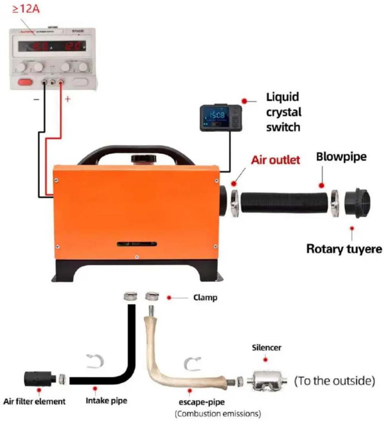
CY-30/CY-32 (Vertical type)
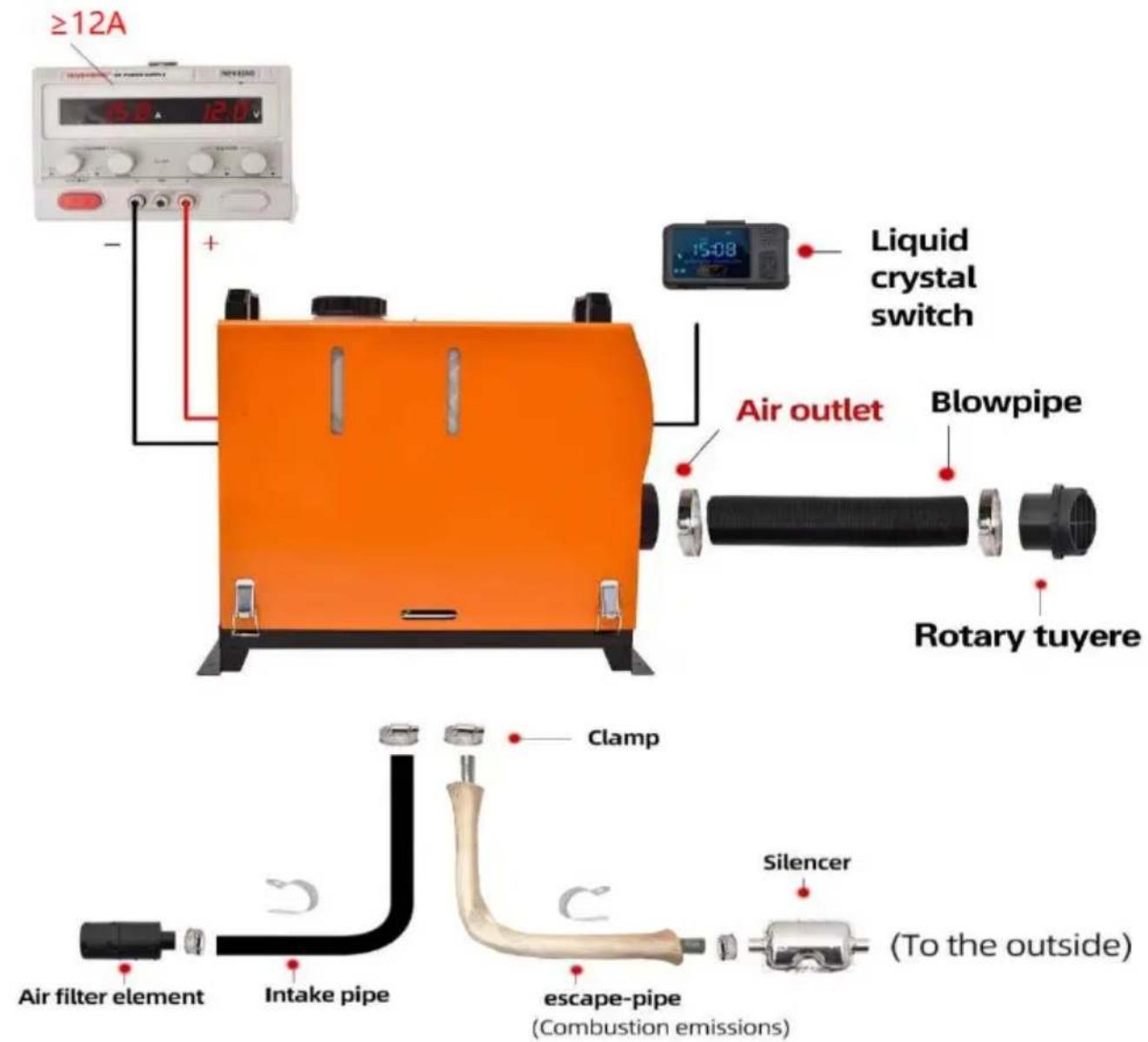

For specific installation, please scan the QR code to view the installation video

Warning:
- The air inlet shall not be blocked to keep it open and clear.
- Keep the exhaust pipe clear. The exhaust pipe outlet shall be kept away from anything flammable, and avoid heating and igniting the flammable goods and loading cargo on the ground.
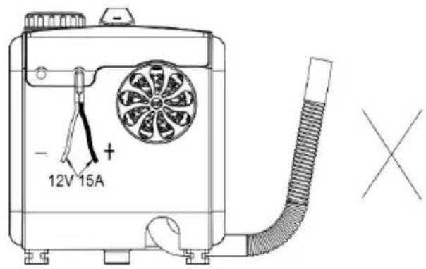
- To ensure optimal combustion, please remember that the smoke exhaust pipe cannot be placed upward, but must be placed horizontally or downward.
Panel operation instructions
Please refer to the instructions be for the LCD screen switch usage. To sync, scan the QR code on t right to watch the video.

- Three-button digital-LCD switch [voice type]
 | |||
| Function | Parameter | Operation method | Specific operational steps |
| Power on | / | Short press the power on/off button | In the shutdown state, press the p button briefly to turn on the device. When the screen displays temperat or H-number, it indicates that the device has been turned on for hea |
| Shutdown | / | Short press the power on/off button | In the power-on state, short press 'power on/off button' to display 'OF shut down. During the shutdown process, the button cannot be operated. Wait for the fan to stop working, and the language will announce that the heating will stop the machine will be completely shu down;Note: It is forbidden to forcefully c the power during the shutdown process. Otherwise, the internal hea will not be completely dissipated. A second startup will produce a large amount of smoke, and incomplete dissipation can easily damage the internal wind turbine of the machine this time, it is necessary to wait f internal to completely burn before returning to normal. |
| Display time | 24-hour clock system | Display in standby mode | After powering on, the screen displ Display Time 'in standby mode, an automatically switches to' Display Ti'in standby mode after shutdown.In the power-on state, long press for 2 seconds to enter the time of long press [Power button] for 2 seconds [Hour flashing], press [Left]&[Right] to adjust to the current time, long press [Power button] for seconds [Minute flashing], press [Left]&[Right] to adjust to the current time, long press [Left] for 2 seconds save and exit.S1 is to adjust the current time so S2 runtime setting; S3 timed power on/off settings; S4 timed on and o settings;Note: The display time will automatically reset to zero after a power failure, and there is no mer saving function. |
| run time | 9999min | Display during work process | Automatically timed after startup, allowing real-time observation of working time. |
| Gear mode | Levels 1-6 | Left and Right Click t Adjust Gear | Default gear mode upon startup, [le button]&[right button] adjust the gear size.The lowest gear is 1st gear, at the highest gear is 6th gear. |
| Gear/Temperature Switching | / | Long press the power button for 2 seconds | Default gear mode when turned on long press the [power on/off button 2 seconds to switch temperature m Short press the left and right button adjust the temperature. |
| Temperature - Celsius | 8~36°C | Long press the power button for 2 seconds | In the power-on state, long press [power on/off button] for 2 seconds display Celsius degrees. |
| Temperature - | 46~97°F | Long press | In the power-on state, long press |
| Fahrenheit | the power button for 2 seconds | [power on/off] button for 2 seconds display Celsius degrees, and long press the [right-click] button for 2 seconds to switch to Fahrenheit degrees. Short press the left and buttons to adjust the temperature. | |
| Manual oil pump | Maximum 300 second countdown | Long press the [left button] for 3 seconds | When powered on for the first time press and hold the [left button] for seconds to automatically pump oil 300 seconds. When the oil pump appears on the screen, it indicates the oil is being manually pumped. the end, it will automatically stop, you can short press the [power or button] to stop halfway. The disappearance of the oil pump icon indicates successful shutdown.Note: Observe the oil inlet at the bottom of the machine and stop pumping oil until it reaches the inlet position. Excessive pumping of oil cause excessive internal oil volume and failure to ignite. |
| Remote control matching | Effective distance ≤ 30m | Long press [right-click] for 2 seconds | In standby mode, long press the [click] button for 2 seconds to disp [rtE]. Press any key on the remote control to successfully match and e the matching process |
| Remote control function | Effective distance ≤ 30m | Factory default matching | [ON] - power button, [OFF] - power button, [+/-] - gear/temperature size |
| Timer setting | Maximum 10 hours | Minimum running time of 30 minutes | In the power-on state, press and h the [left button] for 2 seconds to the time setting, [S01] the current setting; [S02] Start time setting; [S0 Set the scheduled running time; [S Set the timer function switch, right- to select:1. [S01] Current Time Setting: [S01 Interface, long press the [Power On/Off] button for 2 seconds [hour flashing], press the [Left]&[Right] buttons to adjust to the current time long press the [Power On/Off] butto for 2 seconds [minute flashing], pre the [Left]&[Right] buttons to adjust the current time, long press the [L button for 2 seconds to save and 2. [S02]Start time setting: On the interface, long press the [power on button] for 2 seconds[hour flashing], press [left]&[right]to adjust to the current time, long press the[power on/off button]for 2 seconds[minute flashing], press [left]&[right] to adjust the current time, long press the [le button] for 2 seconds to save and 3. [S03] Set the scheduled running time; On the [S03] interface, long the [Power On/Off] button for 2 seconds [hour flashing], press the [Left]&[Right] buttons to adjust to the current time, long press the [Power On/Off] button for 2 seconds [minu flashing], press the [Left]&[Right] buttons to adjust to the current tim long press the [Left] button for 2 seconds to save and exit.4. [S04 ] Timer function switch set On the [S04] interface, long press [power on/off] button for 2 seconds off flashing], press the [left]&[right] buttons to turn on [t-on flashing], I press the [left] button for 2 second save and exit. When in standby m the alarm icon displayed on the sc indicates a successful setting.Note: Set the start time and run t sequence, for example: if the curre |
| time is 15:00, set it to start at 15 run it at 15:40 and close it | |||
| Voice Announcements | Voice broadcasting during startup, shutdown, and fault code situations | Factory default English | After turning on the device, long p the combination of the [left button] [power on/off button] for 2 seconds display the voice selection interface. Release it and it will automatically standby mode; [U-FU]-Russian, [U-EN]-English, [U-GE]-German, [U-OF]-Voice off |
| Basic information | / | Press the power button and right-click combination key for 2 seconds to enter basic information | In the power-on state, simultaneous press and hold the [Power On] an [Right] combination keys for 2 sec to enter the basic settings. Press t [Left] and [Right] keys to select, at the display area will show data dis items. Short press the [Power On] to exit;01: Shell temperature [XX °C];02: Power supply voltage [P-12V];03: Current gear [- X -];04:Environmental temperature [P-XX °C]; |
2. Three key digital LCD switch [standard version]
| Toll 12:00 13:00 | |||
| Function | Parameter | Operation method | Specific operational steps |
| Power on | / | Short press the power on/off button | In the shutdown state, pres the power button briefly to on the device. When the screen displays temperature or H-number, it indicates that the device has been turned for heating. |
| Shutdown | / | Short press the power on/off button | In the power on state, should press the 'power on/off but to display 'OFF' to shut do During the shutdown process the button cannot be operate Wait for the fan to stop working, and the language announce that the heating stop and the machine will completely shut down; Note: It is forbidden to forcefully cut off the power during the shutdown process Otherwise, the internal heat will not be completely dissipated. A second startup will produce a large amount smoke, and incomplete heat dissipation can easily damage the internal wind turbine of machine. At this time, it is necessary to wait for the internal to completely burn before returning to normal. |
| Display time | 24-hour clocksystem | Display in standbymode | After power on, the screen displays' Display Time 'in standby mode, andautomatically switches to' Display Time 'in standby mo after shutdown.In the power on state, long press [Left] for 2 seconds t enter the time option, long press [Power button] for 2 seconds [Hour flashing], pres [Left]&[Right] to adjust to the current time, long press [Power button] for 2 second [Minute flashing], press [Left]&[Right] to adjust to the current time, long press [Le for 2 seconds to save and e S1 is to adjust the current setting; S2 runtime setting; timed power on/off settings; S4 timed on and off settings; Note: The display time will automatically reset to zero after power failure, and there is no memory saving function. |
| run time | 9999min | Display during work process | Automatically timed after startup, allowing real-time observation of working time. |
| Gear mode | Levels 1-6 | Left and Right Click to Adjust Gear | Default gear mode upon startup, [left button]&[right button] adjust the gear size.The lowest gear is 1st gear, and the highest gear 6th gear. |
| Gear/Temperature Switching | / | Long press the power button for 2 seconds | Default gear mode when turned on, long press the [power on/off button] for 2 seconds to switch temperature mode. Short press the left right buttons to adjust the temperature. |
| Temperature - Celsius | 8~36°C | Long press the power button for 2 seconds | In the power on state, long press the [power on/off but for 2 seconds to display Celsius degrees. |
| Temperature - Fahrenheit | 46~97°F | Long press the power button for 2 seconds | In the power on state, long press the [power on/off] but for 2 seconds to display Celsius degrees, and long press the [right-click] button for 2 seconds to switch to Fahrenheit degrees. Short press the left and right but to adjust the temperature. |
| Manual oil pump | Maximum 300 second countdown | Long press the [left button] for 3 seconds | When powered on for the first time, press and hold the [left button] for 3 seconds to automatically pump oil for 30 seconds. When the oil pump icon appears on the screen, it indicates that the oil is being manually pumped. After the end, it will automatically stop or you can short press the [power on/off button] to stop halfway. The disappearance of the oil pump icon indicatessuccessful shutdown.Note: Observe the oil inlet the bottom of the machine stop pumping oil until it reaches the inlet position.Excessive pumping of oil ca cause excessive internal oil volume and failure to ignite. |
| Remote control matching | Effective distance ≤ 30m | Long press [right-click] for 2 seconds | In standby mode, long pres the [right-click] button for 2 seconds to display [rtE]. Press any key on the remote control to successfully match and exit the matching process |
| Remote control function | Effective distance ≤ 30m | Factory default matching | [ON] - power button, [OFF] - power button, [+/-] - gear/temperature size |
| Timer setting | Maximum 10 hours | Minimum running time of 30 minutes | In the power on state, press and hold the[left button] for seconds to enter the time setting, [S01] the current time setting; [S02] Start time setting; [S03] Set the scheduled running time; [S04] Set the timer function switch right-click to select:1. [S01] Current Time Setting: [S01]Interface, long press the [Power On/Off] button for 2 seconds [hour flashing], press the [Left]&[Right] buttons to adjust to the current time, press the [Power On/Off]button for 2 seconds [minute flashing], press the [Left]&[Right] buttons to adjust to the current time, long press the [Left] button for 2 sec to save and exit.2. [S02]Start time setting: O the [S02] interface, long press the [power on/off button] for second[hour flashing], press [left]& [right] to adjust to the current time, long press the[power on/off button]for 2 second[minute flashing], pres [left]&[right] to adjust to the current time, long press the [left button] for 2 seconds save and exit.3. [S03] Set the scheduled running time; On the [S03] interface, long press the [Power On/Off] button for 2 seconds [hour flashing], pres the [Left]&[Right] buttons to adjust to the current time, long press the [Power On/Off] button for 2 seconds [minut flashing], press the [Left]&[Right] buttons to adjust to the current time, long press the [Left] button for 2 sec to save and exit.4. [S04] Timer function switch setting; On the [S04] interfa long press the [power on/ofbutton for 2 seconds [t-off flashing], press the [left] & [right] buttons to turn on [t-flashing], long press the [left] button for 2 seconds to say and exit. When in standby mode, the alarm icon displayed on the screen indicates a successful settingNote: Set the start time at run time in sequence, for example: the current time is 15:00, set it to start at 15:run it at 15:40 and close i |
| Basic information | / | ress the power button and right-click combination key for 2 seconds to enter basic information | In the power on state, simultaneously press and ho the [Power On] and [Right] combination keys for 2 seconds to enter the basic settings. Press the [Left] and [Right] keys to select, and display area will show data display items. Short press t [Power On] key to exit;01: Shell temperature [XX °C]02: Power supply voltage [P-12V];03: Current gear [- X -];04: Environmental temperature [P-XX °C]; |
3.Blue Screen - LCD Switch [Standard Version]
![Vevor CY-29 - 3.Blue Screen - LCD Switch [Standard Version] - 1](/content/2026/04/734759/images/e4810b4e03956419da93d255f9bb9b475832a3cf78e68a7433ae2797e6cf7efa.jpg) ![Vevor CY-29 - 3.Blue Screen - LCD Switch [Standard Version] - 2](/content/2026/04/734759/images/a20a6df529833da67a7d7b6fe85cf78c27aacb4f216fd098027f2c0ac7f077be.jpg) | |||
| Function | Parameter | Operation method | Specific operational steps |
| Power on | / | Long press the [power on/off button] | In the shutdown state, press and hold the pow button for 2 seconds to turn on and start heating. When the screen display the H-number, it indicate that the device has been turned on and heated u |
| Shutdown | / | Long press the [power on/off button] | In the power on state, press and hold the [pow on/off button] for 2 seconds to display 'OFF' for shutdown. During the shutdown process, the button cannot be operate. Wait for the fan to stop working and the language will announce that the heating will stop, and the machine will be completely shut down; Note: It is forbidden to forcefully cut off the pow during the shutdown process. Otherwise, the internal heat will not becompletely dissipated. A second startup will produce a large amount smoke/incomplete heat dissipation, which can easily damage the intern wind turbine of the machine |
| Display time | 24-hour clock system | Display in standby mode | In the power on state, press and hold the [pow on/off button] for 2 seconds to display 'OFF' for shutdown. During the shutdown process, the button cannot be operate. Wait for the fan to stop working and the language will announce that the heating will stop, and th the machine will be completely shut down; Note: It is forbidden to forcefully cut off the pow during the shutdown process. Otherwise, the internal heat will not be completely dissipated. A second startup will produce a large amount smoke/incomplete heat dissipation, which can easily damage the intern wind turbine of the machine |
| run time | 99 hours and 59 minutes | Display during work process | Automatically timed after startup, allowing real-time observation of working time. |
| Gear mode | Levels 1-6 | Left or Right Click to Adjust Gear | Default gear mode upon startup, short press [left button]&[right button] to adjust the gear size. |
| Gear/Temperature Switching | / | Long press the [Settings]button for 2 seconds | Default gear mode when turned on, long press th【 Settings】button f seconds to switch temperature mode. Short press the left and right buttons to adjust the temperature |
| Temperature - Celsius | 0~40°C | Long press the [Settings]button for 2 seconds | In the power on state, press and hold the [Settings] button for 2 seconds to display Celsius degrees. Short press the left and right buttons to adjust the temperature |
| Temperature - Fahrenheit | 32~104°F | Long press the [Settings]button for 2 seconds | In the power on state, press the [Settings] button for 2 seconds to display Celsius degrees, and lon press the [Left]&[Power On] combination button 12 seconds to switch Fahrenheit degrees. Short press the left and right buttons to adjust thetemperature. |
| Manual oil pump | Long press the[Left]&[Right] buttons for 3 seconds | In standby mode, long press the [left button]&[right button] for seconds to automatically pump oil. When the oil pump icon appears on t screen, it indicates that oil is being manually pumped. Stop pumping after releasing the button and the disappearance of the oil pump icon indicate the end of manual pumping.Note: Observe the oil at the bottom of the machine and stop pumping oil until it react the inlet position.Excessive pumping of oil can cause excessive internal oil volume and failure to ignite. | |
| Remote control matching | Effective distance ≤ 30m | Long press the power button and left button combination key for 2 seconds | In standby mode, press and hold the [power on/ button]&[right button] combination key for 2 seconds to display [HFR Press any key on the remote control to successfully match and exit the matching proces |
| Remote control function | Effective distance ≤ 30m | Factory default matching | [ON] - power button, [O - power button, [+/-] - gear/temperature size |
| Timer setting | Maximum 23 hours and 59 minutes | Minimum running time of minutes | In standby mode:1. Current time setting: Long press the [OK] but for 2 seconds to enter time option, short press the [Power On/Off] butto to select hours and minutes, press the [Left]&[Right] buttons to adjust to the current tim short press the [OK] but to confirm, enter the [Week Options], press th [Left]&[Right] buttons to adjust the star period, short press the [OK] but to save and exit.2. Timer startup time setting: Long press the 【 Right】&【 OK】key combination for 2 secon to enter the time setting press the 【 Left】& 【 Right】key to set hour and minute, press 【 Power On】key t enter the hour and minu selection, and then short press the 【 OK】ke set the timer shutdown time; Press the left andright buttons to set the hour and minute settings Short press the power button to enter the hour and minute selection. After completion, press the OK button to confirm and save to exit. Confirm to save and exit. When the screen displays an alarm during standby, it means the setting is successful.3. Cancel the timing method; When the timer function is activated, pre and hold the【 right-click 】&【 OK 】key combination for 2 second to turn off the timer function. When the alarm icon on the screen disappears, it means it been successfully turned offNote: After setting the current time, sequentially set the startup time and shutdown time. For example, if the current time is 15:10, set it to at 15:12 and run and down at 15:17,Warning: Timer startup and timer shutdown need to be set simultaneouslyand cannot run independently. After setting the timer to start it will be repeated every day. When not in use, follow the cancel timer method to turn off the timer. |
| Basic information | / | ress the power button and right click combination key for 2 seconds enter basic information | In the power on state, press the [OK] key to e the basic settings and v information:01: Shell temperature [XXX °C]; 02: Power supply voltage [P-12V]; 0 Environmental temperature [PXX °C]; 04 Current gear [H-X]; |
Fault table
Fault alarm
Show the following figure, corresponding to the failure symbol flicker, and corresponding to the failure device icon flicker, display data as fault code, its meaning please refer to the fault table.
*Spark plug, oil pump, fan, sensor, power supply and other symbols, flicker indicates that the corresponding device is failing.
Fault table
| Scan the QR code to view the troubleshooting method |  |
| Fault code | Cause of failure | solutions |
| E-01/E-02 | Abnormal supply voltage and curren | 1. Check the power supply equipment to ensu the input voltage is 12V/24V and the input cu ≥ 15A, power: ≥ 150W, there may be losses differences in installation wire diameter and len 1 12V power supply: can be started under t conditions of minimum voltage ≥ 10V and min current 9.5A; 2 24V power supply: It can be under the conditions of minimum voltage ≥ 24 minimum current 4A Over voltage protection>32 reports E-01/E-02 fault.2. Power supply equipment selection: recommended for power supply, battery, adapte etc. Input voltage: 12V/24V, input current: ≥ 1 power: ≥ 150W.3. Charging the battery with a heater is prohi as low battery current can cause it to malfun 4. Prohibit the use of in-car cigarette lighters power supply, as low current cannot work; 5. It is forbidden to use fixtures to fix the co between the battery and the wires, as poor o can also cause malfunction. When extending tl wire harness, attention should be paid to wire a diameter of ≥ 2mm ^2 to avoid voltage drop by thin wire diameter, and low voltage or cur causing malfunction. If the wire harness does work after being extended, measure the voltag current at the power supply end and the hea harness end. |
| E-03 | Ignition plug malfunction | 1. Check if the ignition plug is securely connected2. Remove the ignition plug and inspect the appearance for any defects such as broken with harness, broken ignition plug head, oxidation, carbonization, etc.3. Replace with new ignition plug accessories. |
| E-04 | Oil pump malfunction | 1. Check if the oil pump plug is loose, unplureinstall it to confirm.2. Confirm if there is any pumping sound in pump. If there is no pumping sound, there might impurities inside after repeated tapping after disassembly.3. The oil pump has malfunctioned, please re- it. |
| E-05 | Over-Temperature Protection | The temperature sensor detects that if the sur temperature of the aluminum body is ≥ 280 ° provide over-temperature protection. Pay attention to checking whether the inlet, outlet, and exha pipes are bent or too long, which affects the and prevents heat from dissipating. |
| E-06 | Wind turbine motor malfunction | 1. Check if the motor rotor is stuck, if the p loose, if the connection is incorrect, etc. If it use two screwdrivers to move it parallel outwa and return to normal.2. Check if the distance between the Huo se and the rotor magnet is too far, and if it can sense the rotor speed, causing an E-06 fault to be reported;3. Check if the induction magnet of the wind is missing or has incorrect polarity, and adjust restore normal operation.4. The motor and motherboard have malfunction. Please replace the motor or motherboard. |
| E-07 | Communication Failure | 1. Check if the connection port of the rem control switch is loose2. Check if the connecting wire (blue) of remote control switch is open circuited |
| E-08 | Secondary ignition failure(Oil circuit malfunction) | The program will automatically detect whether is an oil pump entering the machine, performchecks, and each check takes 4 minutes;1. Newly purchased machines need to be fille diesel in the fuel tank and patiently wait for minutes before starting the heating process. If is no oil in the oil pipe of the new machine, start slowly.2. Check if the diesel in the fuel tank has b completely burned, and observe the fuel tank to confirm if the fuel is sufficient. If there is the tank, replenish it in a timely manner befo starting the machine and heating it up normal3. Refer to the troubleshooting method for E-1 code. |
| E-09 | sensor fault | 1. Check if the temperature sensor connection and connector are damaged or loose, and if no signal detected by the motherboard prograr to signal interruption.2. Replace sensor accessories. |
| E-10 | One ignition failure (Oil circuit malfunction) | 1. Check if there is enough oil in the fuel ta oil pipe, if the oil pipe is blocked, and if the is stuck.2. Check if the intake and exhaust pipes are unobstructed. Insufficient oxygen intake or poor exhaust can cause ignition failure.3. Does the altitude exceed the calibration parameters? Insufficient oxygen intake can caus ignition failure;4. Refer to the E-01/E-02 fault code check, t ignition failed due to insufficient heat from the point spark plug of the power supply voltage/current. |
| Installation Guide | The surface temperature of the exhaust pipe is around 752 °F, an attention should be paid to protection against flammable materials during installation | 1. Please note that there are no flammable substances around the exhaust pipe and muffle air outlet, and insulation materials should be u for protection. It is forbidden to drill holes and machines on wooden floors. The surface temperature of the exhaust pipe is around 7522. Prohibit the use of nonhigh temperature res adhesives to avoid odor poisoning, and be ca avoid causing fires by igniting flammable mate3. Installation position: 1 Reserve a 4-inch gthe air inlet for smooth air intake; 2 Keep t bottom exhaust pipe at a distance of 2 inch the ground, and prevent fires when the exhaust temperature is high Do not bend the exhaust excessively, as it may cause poor exhaust flow. The exhaust duct is not easily too long and bends can cause heat to be unable to be discharged, resulting in a high-temperature fault. When refueling the fuel tank, do not let it flow the outer shell, as it will flow along the inside machine to the exhaust pipe position, causing smoke. Fill the fuel tank to a level close to tank opening. Do not block the intake pipe as cause insufficient oxygen and the heater to malfunction. |
| Accessories modification | Prohibit the use of nonhigh temperature resistant materials and rubber seals that may cause odor and poisoning hazards | 1. Extension of exhaust duct modification: It is recommended to purchase pipes made of the material or high-temperature resistant material, a length controlled within 2 meters and no la angle bending to avoid overheating.2. Exhaust pipe modification and extension: It recommended to purchase pipes made of the material or high-temperature resistant stainless steel material, with a length controlled within 2 meters and no large angle bending. The pipes be discharged downwards to the outside and be bent upwards multiple times to affect exhaust heat dissipation (the working temperature of the exhaust pipe reaches around 752 °F, and the installation position is prohibited from drilling ho in the wooden floor. Nonhigh temperature resis rubber seals are also prohibited, which may c odor and poisoning hazards). |
| Emitting white smoke | Abnormal power outage/excessive manual pump oil volume | 1. Manually pump oil, if there is too much of the machine, it will not ignite and emit white. The correct way is to pump oil to the inlet p and stop. If the pump oil volume is too high, pipe should be unplugged and restarted 2-3 ti restore normal operation before inserting the o pipe; Or use a hair dryer to blow towards the pipe for a period of time until it works prope2. Abnormal power outage during operation: D normal operation, press the 'power on/off butto display 'OFF' for shutdown. During the shutdown process, the button cannot be operated. Wait fan to stop working before completely shutting down, and then disconnect the power supply. During the shutdown process, it is forbidden to forcefully cut off the power. Otherwise, the int heat will not be completely dissipated and a amount of smoke will be generated during the second startup. At this time, it is necessary to for the internal to completely burn before return to normal.3. Refer to E-01/E-02 fault code troubleshooting |
| Smoking | Insufficient oxygen intake or carbon deposition in the combustion chamber | 1. Does the altitude exceed the calibration parameters? Insufficient oxygen intake can cause ignition failure and black smoke emission.2. Check if there is any blockage in the int causing insufficient oxygen intake.3. The small space at the air inlet position le air intake obstruction.4. Refer to the E-01/E-02 fault code check, the point of the power supply voltage/current has insufficient heat from the ignition plug, resulting ignition failure and black smoke emission.5. Disassemble the internal combustion chamber the machine to check for carbon deposits and replace the combustion chamber in a timely manner. |
| Smoke blue | Poor oil quality | Only high-grade diesel can be used, and the mixed diesel, other types of oil, and non-branc oil products is prohibited. In winter, negative temperature diesel should be met; |
| Machine oil leakage | Oil tank/pipe damage, side installation (Side installation prohibited) | 1. Check the appearance of the fuel tank/oil and whether the fuel tank nozzle is damaged cracked, which may cause oil leakage.2. When filling the fuel tank with diesel, be not to pour it onto the machine casing. Other will flow into the interior and smoke due to h internal heat during operation.3. The heater cannot be installed on the sideoxygen hole oil on the ignition plug side will through the hole, and the correct installation is to have the intake/exhaust port facing downwards;4. Poor oil quality leads to blockage of the plug atomization network in the combustion chamber, causing ignition to flow out through exhaust pipe. The ignition plug atomization net and high-grade diesel should be replaced. |
| There is no oil or heat inside the machine | The oil pipe is be | Check if there are any bent positions in the that prevent air from supplying oil. |
| Oil flowing through the exhaust pipe | Excessive pump oil volume/blocked atomization network/abnormal voltage | 1. Manually pumping oil, if there is too much inside the machine, it will not ignite and emit smoke. If the combustion chamber is filled with excessive pumping oil, it will flow out from the exhaust pipe; The correct way to pump oil to inlet position and stop. If the pump oil volume high, the oil pipe should be unplugged and re 2-3 times to restore normal operation before inserting the oil pipe; Or use a hair dryer to towards the intake pipe for a period of time works properly.2. The ignition plug atomization net is blocked removing the ignition plug, take out the internal atomization net and check for any blockage. I should be cleaned or replaced immediately. |
| Oil flowing inside the intake pipe | Incorrect installation direction/excessive manual pump oil volume | 1. Manually pumping oil, if there is too much inside the machine, it will not ignite and emit smoke. If the combustion chamber is filled with excessive pumping oil, it will flow out from the pipe; The correct way to pump oil to the inlet position and stop. If the pump oil volume is the oil pipe should be unplugged and restarted times to restore normal operation before insert the oil pipe; Or use a hair dryer to blow to intake pipe for a period of time until it works properly.2. The heater cannot be installed on the side oxygen hole oil on the ignition plug side willthrough the hole, and the correct installation is to have the intake/exhaust port facing downwards. |
| The exhaust pipe temperature is too high and turns red | Combustion chamber malfunctions | Immediately shut down, dismantle the aluminum body to check if the internal combustion chamber sealed or replace the combustion chamber. |
| abnormal sound | Poor exhaust flow | Foreign matter blockage in the exhaust pipe at the exhaust. It should be immediately shut down and the exhaust pipe, muffler, and exhaust po should be checked for blockage. If there is a blockage, it should be cleaned and restored to normal operation. |
| Diesel odor | Oil leakage/fuel error | 1. Only high-grade diesel can be used, and to of mixed diesel, other types of oil, and non-b new oil products is prohibited. In winter, negative temperature diesel should be met, as other fuel may cause odors.2. Disassemble the machine casing to check oil leaks inside and replace the parts promptly |
| Plastic smell | Use external accessories | 1. Extension or modification requires the purchase of high-temperature resistant accessories. If the heater has high heat, it may produce unpleasant and pungent odors.2. Extend the pipe fittings without bending or too long, as this can cause heat to be unable to dissipate and result in high internal temperature plastic odor.3. The working temperature of the exhaust pipe reaches around 752 °F. It is prohibited to drill in the wooden floor or use non-high-temperature resistant rubber seals for installation, which may cause odor and poisoning hazards. |
| Maintenance | Smoking/insufficient heat | If black smoke or insufficient heat is found due to the operation of the heater for a period of time indicates that there is carbon deposition inside combustion chamber and it needs to be clean replaced in a timely manner. |
| Fuse burnt ou | Short circuit power off inspection | 1. Remove the fuse and check for damage. I damaged, replace the fuse.2. Measure whether the positive and negative are short circuited. If there is a short circuit, the motherboard if it is damaged. |
Manufacturer: Shanghaimuxinmuyeyouxiangongsi
Address: Shuangchenglu 803nong11hao1602A-1609shi, baoshanqu, shanghai 200000 CN.
Imported to AUS: SIHAO PTY LTD.
1 ROKEVA STREETEASTWOOD NSW 2122 Australia
Imported to USA: Sanven Technology Ltd.
Suite 250, 9166 Anaheim Place, Rancho Cucamonga, CA 91730
| UK | REP |
YH CONSULTING LIMITED.
C/O YH Consulting Limited Office 147,
Centurion House, London Road, Staines-upon-Thames, Surrey, TW18 4AX
| EC | REP |
E-CrossStu GmbH
Mainzer Landstr.69,
60329 Frankfurt am Main.
VEVOR®
TOUGH TOOLS, HALF PRICE
VEVOR®
TOUGH TOOLS, HALF PRICE
natural_image
Red VEVOR industrial gas stove with control panel and water tank (no visible text or symbols)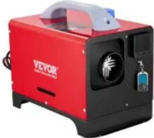
natural_image
Red and black Veyor industrial machine with visible branding and control panel (no readable text beyond branding)MODÈLE : CY-29 MODÈLE : CY-32

natural_image
Orange VEVOR portable dust collector device with black handle and control panel (no visible text or symbols)
natural_image
Orange VEVOR industrial machine with visible control panel and mechanical components (no text or symbols on device body)NEED HELP? CONTACT US!
Have product questions? Need technical support? Please feel fr contact us:
Technical Support and E-Warranty Certificate www.vevor.com/support
This is the original instruction, please read all manual instruction carefully before operating. VEVOR reserves a clear interpretation user manual. The appearance of the product shall be subject to product you received. Please forgive us that we won't inform you there are any technology or software updates on our product.
Installing insulation sleeves on exhaust pipes can effectively reduce surface temperature and prevent fire hazards caused by improper installation.

natural_image
Close-up of a mechanical component with a wooden handle and green cable, no visible text or symbols
natural_image
Solid orange right-pointing arrow on white background (no text or symbols)
natural_image
Close-up of a car's side profile showing a wooden floor and a red-lit vent (no text or symbols visible)- On the co-driver's legroom.
- On the back wall of the cab.
- Driver's seat backrest.
- Within the tool box.

- In front of the passenger seat.
- Between the driver seat and passenger seat
- 3 & 4 under the container.
- In the trunk.
The heater is mainly installed in the passer room or baggage room of the vehicle. If it be installed, fix the heater under the unders of the vehicle, but beware of splashing.

- Inside the driver's seat.
- On the back wall of the ca
- Inside the protection box.

natural_image
Orange Vevor industrial machine with a highlighted component (no visible text or symbols on the device itself)
natural_image
Industrial robotic device labeled 'VEVOR' in a workshop setting, with no visible text or symbols on the device itself.- Do not use the heater when charging the battery
- The current is low and it does not work
natural_image
Exterior view of a portable electronic device with attached battery and power supply unit (no visible text or symbols)Suggest using energy storage (batteries) or adapters for the power supply
natural_image
Close-up of a mechanical device with wiring and connectors, no visible text or symbolsnatural_image
Electrical wiring setup with battery, switch, and wall-mounted device (no visible text or symbols)natural_image
Electrical wiring setup with a battery, switch, and wall-mounted components (no visible text or symbols)
natural_image
Close-up of a mechanical device mounted on a wall, showing wiring and components (no visible text or symbols)
natural_image
Close-up of a handheld electronic device mounted on a wall, with wires and connectors visible (no text or symbols)Excessive pump oil produces white smoke
Blow the air gun towards the intake pip to assist combustion
Remove the oil pipe and insert it after it normal
Schéma d'inspection
flowchart
graph TD
    A["①: Temperature Control with fan, motor, and cooling unit"] --> B["②: Heat exchanger or cooler"]
    B --> C["③: Processed cooling unit with fan, motor, and cooling unit"]
    C --> D["④: Machine tool in cooling unit"]
natural_image
Black battery with two red X-shaped warning symbols on top, placed indoors (no text or labels visible)Fixing the battery clamp can easily cause poor contact

natural_image
Close-up of a car interior with a red X mark and a tool interacting with a glowing orange flame (no text or symbols visible)Cigarette lighter current low does not work
INSTALLATION DIAGRAM
CY-28/CY-29 ( Type horizontal )
CY-30/CY-32 (Type vertical)


For specific installation, please scan the QR code to view the installation video

Avertissement:
Panel operation instructions
1 ROKEVA STREET, EASTWOOD, NSW 2122, Australie
Suite 250, 9166 Anaheim Place, Rancho Cucamonga, CA 91730
| UK | REP |
YH CONSULTING LIMITED.
C/O YH Consulting Limited Office 147,
Centurion House, London Road, Staines-
upon-Thames, Surrey, TW18 4AX
| EC | REP |
E-CrossStu GmbH
Mainzer Landstr.69,
60329 Frankfurt am Main.
VEVOR®
TOUGH TOOLS, HALF PRICE
VEVOR®
TOUGH TOOLS, HALF PRICE
natural_image
Red VEVOR industrial machine with control panel and water tank (no visible text or symbols)
natural_image
Red and black VEVOR industrial machine with a white cover and control panel (no visible text or symbols on the device body)MODELL:CY-29 MODELL:CY-32

natural_image
Orange VEVOR portable air purifier with black handle and control panel (no visible text or symbols)
natural_image
Orange VEVOR industrial machine with visible control panel and fan (no text or symbols on device body)NEED HELP? CONTACT US!
Have product questions? Need technical support? Please feel fr contact us:
Technical Support and E-Warranty Certificate www.vevor.com/support
This is the original instruction, please read all manual instruction carefully before operating. VEVOR reserves a clear interpretation user manual. The appearance of the product shall be subject to product you received. Please forgive us that we won't inform you there are any technology or software updates on our product.
Installing insulation sleeves on exhaust pipes can effectively reduce surface temperature and prevent fire hazards caused by improper installation.
natural_image
Close-up of a mechanical component with a wooden handle and green internal structure (no visible text or symbols)
natural_image
Solid orange right-pointing arrow on white background (no text or symbols)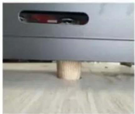
natural_image
Close-up of a car's side panel with a wooden bolt inserted, showing no visible text or symbols.54. WARNUNG: Giftiges Material

- On the co-driver's legroom.
- On the back wall of the cab.
- Driver's seat backrest.
- Within the tool box.

- In front of the passenger seat.
- Between the driver seat and passenger seat
- 3 & 4 under the container.
- In the trunk.
The heater is mainly installed in the passer room or baggage room of the vehicle. If it be installed, fix the heater under the unders of the vehicle, but beware of splashing.

- Inside the driver's seat.
- On the back wall of the ca
- Inside the protection box.

natural_image
Orange Vevor industrial machine with a close-up inset showing a mechanical component (no visible text or symbols)
natural_image
Industrial robotic device labeled 'VEYOR' in a workshop setting, with no visible text or symbols on the device itself.-
Do not use the heater when charging the battery
-
The current is low and it does not work

natural_image
Exterior view of a portable electronic device with battery, charging case, and power supply unit (no visible text or symbols)Suggest using energy storage (batteries) or adapters for the power supply
natural_image
Close-up of a mechanical device with wiring and connectors, no visible text or symbolsnatural_image
Electrical wiring setup with battery, switch, and motor assembly (no visible text or symbols)natural_image
Electrical wiring setup with a battery, switch, and wall-mounted components (no visible text or symbols)
natural_image
Close-up of a mechanical device mounted on a wall, with wiring and a highlighted green box (no visible text or symbols)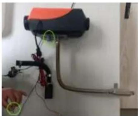
natural_image
Close-up of a handheld electronic device mounted on a wall, with visible wiring and components (no text or symbols)Excessive pump oil produces white smoke
Blow the air gun towards the intake pip to assist combustion
Remove the oil pipe and insert it after it normal
Inspektionsdiagramm
flowchart
graph TD
    A["①: Raw material with cooling unit"] --> B["②: Processed heat exchanger"]
    B --> C["③: Processed cooling unit with cooling fan"]
    C --> D["④: Tool applied to final product"]
natural_image
Black battery with two red X-shaped warning symbols on top, placed indoors (no text or labels visible)Fixing the battery clamp can easily cause poor contact

natural_image
Close-up of a car interior with a red X mark and a tool interacting with a glowing orange flame (no text or symbols visible)Cigarette lighter current low does not work
INSTALLATION DIAGRAM
CY-30/CY-32 (Vertikaler Typ)


For specific installation, please scan the QR code to view the installation video

Warnung:
Panel operation instructions
Suite 250, 9166 Anaheim Place, Rancho Cucamonga, CA 91730
| UK | REP |
YH CONSULTING LIMITED.
C/O YH Consulting Limited Office 147,
Centurion House, London Road, Staines-
upon-Thames, Surrey, TW18 4AX
| EC | REP |
E-CrossStu GmbH
Mainzer Landstr.69,
60329 Frankfurt am Main.
VEVOR®
TOUGH TOOLS, HALF PRICE
VEVOR®
TOUGH TOOLS, HALF PRICE
natural_image
Red VEVOR industrial machine with control panel and water tank (no visible text or symbols)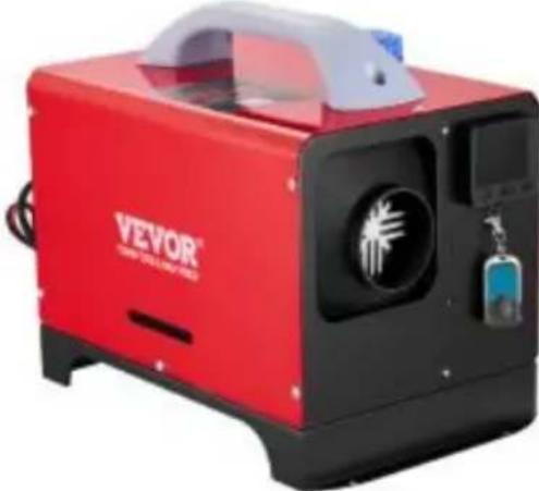
natural_image
Red and black Veyor industrial machine with a white cover and control panel (no visible text or symbols on the device body)MODELLO:CY-29 MODELLO:CY-32

natural_image
Orange and black VEVOR portable air purifier device (no visible text or symbols on body)
natural_image
Orange VEVOR industrial machine with visible control panel and fan (no text or symbols on device body)NEED HELP? CONTACT US!
Have product questions? Need technical support? Please feel fr contact us:
Technical Support and E-Warranty Certificate www.vevor.com/support
This is the original instruction, please read all manual instruction carefully before operating. VEVOR reserves a clear interpretation user manual. The appearance of the product shall be subject to product you received. Please forgive us that we won't inform you there are any technology or software updates on our product.
Installing insulation sleeves on exhaust pipes can effectively reduce surface temperature and prevent fire hazards caused by improper installation.

natural_image
Close-up of a mechanical component with a wooden handle and green internal structure (no visible text or symbols)
natural_image
Solid orange right-pointing arrow on white background (no text or symbols)
natural_image
Close-up of a car's side panel with a wooden bolt inserted, showing no visible text or symbols.- On the co-driver's legroom.
- On the back wall of the cab.
- Driver's seat backrest.
- Within the tool box.

- In front of the passenger seat.
- Between the driver seat and passenger seat
- 3 & 4 under the container.
- In the trunk.

The heater is mainly installed in the passer room or baggage room of the vehicle. If it be installed, fix the heater under the unders of the vehicle, but beware of splashing.

- Inside the driver's seat.
- On the back wall of the c
- Inside the protection box.

natural_image
Orange Vevor industrial machine with a highlighted component (no visible text or symbols)
natural_image
Industrial robotic device labeled 'VEYOR' in a workshop setting, no visible text or symbols on the device itself.-
Do not use the heater when charging the battery
-
The current is low and it does not work
natural_image
Exterior view of a portable electronic device with battery, charging case, and power supply unit (no visible text or symbols)Suggest using energy storage (batteries) or adapters for the power supply
natural_image
Close-up of a mechanical device with wiring and connectors, no visible text or symbolsnatural_image
Electrical wiring setup with battery, switch, and wall-mounted device (no visible text or symbols)natural_image
Three-panel photo sequence showing a device mounted on a wall, with wiring and a hand interacting near a device (no visible text or symbols)Excessive pump oil produces white smoke
Blow the air gun towards the intake pip to assist combustion
Remove the oil pipe and insert it after it normal
Schema di ispezione
flowchart
graph TD
    A["①: Display unit"] --> B["②: Heat dissipation device"]
    B --> C["③: Cooling fan with screw"]
    C --> D["④: Stabilization of cooling fan with plug"]
natural_image
Black battery with two red X-shaped warning symbols on top, placed indoors (no text or labels visible)Fixing the battery clamp can easily cause poor contact

natural_image
Close-up of a car interior with a red X mark and a tool interacting with a glowing orange flame (no text or symbols visible)Cigarette lighter current low does not work
INSTALLATION DIAGRAM
CY-30/CY-32 (Tipo vertical)

For specific installation, please scan the QR code to view the installation video

Avvertimento:
Panel operation instructions
Importato in AUS: SIHAO PTY LTD.
1 ROKEVA STREETEASTWOOD NSW 2122 Australia
Suite 250, 9166 Anaheim Place, Rancho Cucamonga, CA 91730
| UK | REP |
YH CONSULTING LIMITED.
C/O YH Consulting Limited Office 147,
Centurion House, London Road, Staines-
upon-Thames, Surrey, TW18 4AX
| EC | REP |
E-CrossStu GmbH
Mainzer Landstr.69,
60329 Frankfurt am Main.
VEVOR®
TOUGH TOOLS, HALF PRICE
VEVOR®
TOUGH TOOLS, HALF PRICE
Installing insulation sleeves on exhaust pipes can effectively reduce surface temperature and prevent fire hazards caused by improper installation.

natural_image
Close-up of a mechanical component with a wooden handle and green cable, no visible text or symbols
natural_image
Solid orange right-pointing arrow on white background (no text or symbols)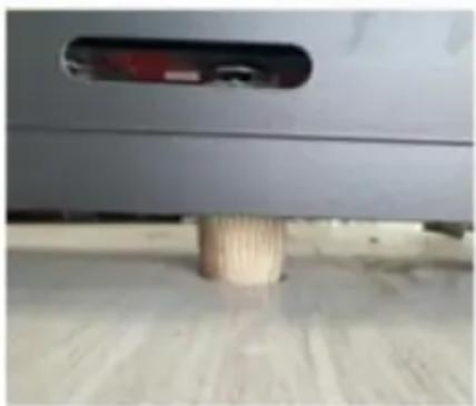
natural_image
Close-up of a car's side profile showing a wooden floor and a red-lit vent (no text or symbols visible)90. ADVERTENCIA: Material tóxico

- On the co-driver's legroom.
- On the back wall of the cab.
- Driver's seat backrest.
- Within the tool box.
- In front of the passenger seat.
- Between the driver seat and passenger seat
- 3 & 4 under the container.
- In the trunk.

The heater is mainly installed in the passer room or baggage room of the vehicle. If it be installed, fix the heater under the unders of the vehicle, but beware of splashing.

- Inside the driver's seat.
- On the back wall of the c
- Inside the protection box.

natural_image
Orange Vevor industrial machine with a close-up inset showing a mechanical component (no visible text or symbols)
natural_image
Industrial robotic device labeled 'VEVOR' in a workshop setting, with no visible text or symbols on the device itself.-
Do not use the heater when charging the battery
-
The current is low and it does not work

natural_image
Exterior view of a portable electronic device with battery, charging case, and power supply unit (no visible text or symbols)Suggest using energy storage (batteries) or adapters for the power supply
natural_image
Close-up of a mechanical device with wiring and connectors, no visible text or symbolsnatural_image
Electrical wiring setup with battery, switch, and wall-mounted device (no visible text or symbols)natural_image
Interior view of a room with a battery, wiring, and a wall-mounted device (no visible text or symbols)
natural_image
Close-up of a mechanical device mounted on a wall, showing wiring and components (no visible text or symbols)
natural_image
Close-up of a mechanical device mounted on a wall, with wires and a hand interacting near it (no visible text or symbols)Excessive pump oil produces white smoke
Blow the air gun towards the intake pip to assist combustion
Remove the oil pipe and insert it after it normal
flowchart
graph TD
    A["①: Internal components with battery, fan, and motor"] --> B["②: Assembly of motor and fan"]
    B --> C["③: Component assembly with motor and fan"]
    C --> D["④: Final assembly with motor and fan"]
natural_image
Black rectangular battery with two red X marks on top, placed on a white surface (no text or symbols visible)Fixing the battery clamp can easily cause poor contact
natural_image
Close-up of a car interior with a red X mark and orange flame, showing a tool interacting with a component (no visible text or symbols)Cigarette lighter current low does not work
INSTALLATION DIAGRAM
CY-28/CY-29 (Tipo horizontal)


For specific installation, please scan the QR code to view the installation video

Advertencia:
Panel operation instructions
1 ROKEVA STREET, EASTWOOD, NSW 2122, Australia
Suite 250, 9166 Anaheim Place, Rancho Cucamonga, CA 91730
| UK | REP |
YH CONSULTING LIMITED.
C/O YH Consulting Limited Office 147,
Centurion House, London Road, Staines-
upon-Thames, Surrey, TW18 4AX
| EC | REP |
E-CrossStu GmbH
Mainzer Landstr.69,
60329 Frankfurt am Main.
VEVOR®
TOUGH TOOLS, HALF PRICE
VEVOR®
TOUGH TOOLS, HALF PRICE
MODEL:CY-30 MODEL:CY-28
natural_image
Red VEVOR industrial gas stove with control panel and water tank (no visible text or symbols)
natural_image
Red and black VEVOR industrial machine with a white cover and control panel (no visible text or symbols on the device body)MODEL:CY-29 MODEL:CY-32

natural_image
Orange VEVOR portable air purifier with black handle and control panel (no visible text or symbols)
natural_image
Orange VEVOR industrial machine with visible control panel and fan (no text or symbols on device body)NEED HELP? CONTACT US!
Have product questions? Need technical support? Please feel fr contact us:
Technical Support and E-Warranty Certificate www.vevor.com/support
This is the original instruction, please read all manual instruction carefully before operating. VEVOR reserves a clear interpretation user manual. The appearance of the product shall be subject to product you received. Please forgive us that we won't inform you there are any technology or software updates on our product.
Installing insulation sleeves on exhaust pipes can effectively reduce surface temperature and prevent fire hazards caused by improper installation.
natural_image
Close-up of a mechanical component with a wooden handle and green cable, no visible text or symbols
natural_image
Solid orange right-pointing arrow on white background (no text or symbols)
natural_image
Close-up of a car's side profile showing a wooden floor and a red-lit vent (no text or symbols visible)- On the co-driver's legroom.
- On the back wall of the cab.
- Driver's seat backrest.
- Within the tool box.

- In front of the passenger seat.
- Between the driver seat and passenger seat
- 3 & 4 under the container.
- In the trunk.

The heater is mainly installed in the passer room or baggage room of the vehicle. If it be installed, fix the heater under the unders of the vehicle, but beware of splashing.

- Inside the driver's seat.
- On the back wall of the c
- Inside the protection box.

natural_image
Orange Vevor industrial machine with a highlighted component (no visible text or symbols)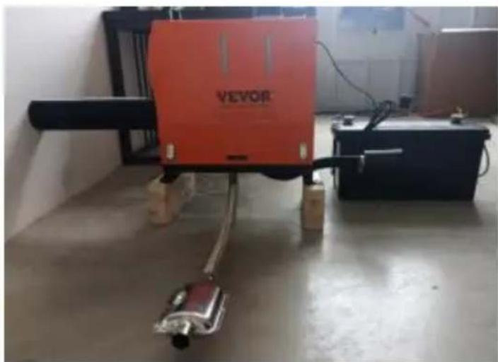
natural_image
Industrial robotic device labeled 'VEYOR' in a workshop setting, with no visible text or symbols on the device itself.- Do not use the heater when charging the battery
- The current is low and it does not work

natural_image
Exterior view of a portable electronic device with battery, charging case, and power supply unit (no visible text or symbols)Suggest using energy storage (batteries) or adapters for the power supply
natural_image
Close-up of a mechanical device with wiring and connectors, no visible text or symbolsnatural_image
Electrical wiring setup with battery, switch, and wall-mounted device (no visible text or symbols)natural_image
Electrical equipment setup with a battery, wiring, and a mounted rack (no visible text or symbols)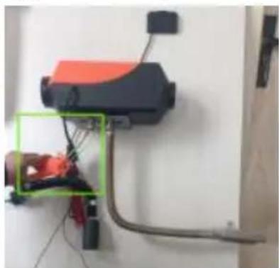
natural_image
Close-up of a mechanical device mounted on a wall, showing wiring and components (no visible text or symbols)
natural_image
Close-up of a handheld electronic device mounted on a wall, with wires and connectors visible (no text or symbols)Excessive pump oil produces white smoke
Blow the air gun towards the intake pip to assist combustion
Remove the oil pipe and insert it after it normal
Schemat inspekcji
flowchart
graph TD
    A["①: Turbocharger with cooling unit"] --> B["②: Heat exchanger"]
    B --> C["③: Top-down turbine with valve"]
    C --> D["④: Stabilized engine housing with screw"]
    D --> E["⑤: Internal combustion chamber"]
natural_image
Black battery with red X-shaped warning symbols on top and side, no visible text or labelsFixing the battery clamp can easily cause poor contact

natural_image
Close-up of a car interior with a red X mark and a tool interacting with a glowing orange flame (no text or symbols visible)Cigarette lighter current low does not work
INSTALLATION DIAGRAM

For specific installation, please scan the QR code to view the installation video

Ostrzeżenie:
Panel operation instructions
1 ROKEVA STREETEASTWOOD NSW 2122 Australia
Importowane do USA: Sanven Technology Ltd.
Apartament 250, 9166 Anaheim Place, Rancho Cucamonga, CA 91730
| UK | REP |
YH CONSULTING LIMITED.
C/O YH Consulting Limited Office 147,
Centurion House, London Road, Staines-
upon-Thames, Surrey, TW18 4AX
| EC | REP |
E-CrossStu GmbH
Mainzer Landstr.69,
60329 Frankfurt am Main.
VEVOR®
TOUGH TOOLS, HALF PRICE
VEVOR®
TOUGH TOOLS, HALF PRICE
Technische ondersteuning en e-garantiecertificaat www.vevor.com/support
DIESELVERWARMING
MODEL:CY-30 MODEL:CY-28

natural_image
Red VEVOR industrial gas stove with control panel and water tank (no visible text or symbols)
natural_image
Red and black VEVOR industrial machine with a white cover and control panel (no visible text or symbols on the device body)MODEL:CY-29 MODEL:CY-32

natural_image
Orange and black VEVOR portable air purifier device (no visible text or symbols on body)
natural_image
Orange VEVOR industrial machine with visible control panel and fan (no text or symbols on device body)NEED HELP? CONTACT US!
Have product questions? Need technical support? Please feel fr contact us:
Technical Support and E-Warranty Certificate www.vevor.com/support
This is the original instruction, please read all manual instruction carefully before operating. VEVOR reserves a clear interpretation user manual. The appearance of the product shall be subject to product you received. Please forgive us that we won't inform you there are any technology or software updates on our product.
Installing insulation sleeves on exhaust pipes can effectively reduce surface temperature and prevent fire hazards caused by improper installation.

natural_image
Close-up of a mechanical component with a wooden handle and green cable, no visible text or symbols
natural_image
Solid orange right-pointing arrow on white background (no text or symbols)
natural_image
Close-up of a car's side profile showing a wooden floor and a red-lit vent (no text or symbols visible)126. WAARSCHUWING: Giftig materiaal

- On the co-driver's legroom.
- On the back wall of the cab.
- Driver's seat backrest.
- Within the tool box.

- In front of the passenger seat.
- Between the driver seat and passenger seat
- 3 & 4 under the container.
- In the trunk.
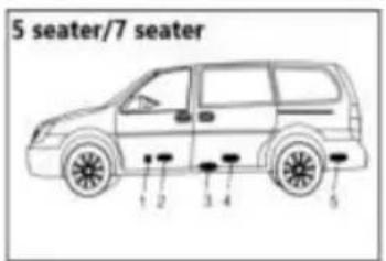
The heater is mainly installed in the passer room or baggage room of the vehicle. If it be installed, fix the heater under the unders of the vehicle, but beware of splashing.

- Inside the driver's seat.
- On the back wall of the c
- Inside the protection box.

natural_image
Orange VEVOR industrial machine with a close-up inset showing a mechanical component (no visible text or symbols)
natural_image
Industrial robotic device labeled 'VEVOR' in a lab setting, with no visible text or symbols on the device itself.- Do not use the heater when charging the battery
- The current is low and it does not work

natural_image
Exterior view of a portable electronic device with battery, charging case, and power supply unit (no visible text or symbols)Suggest using energy storage (batteries) or adapters for the power supply
natural_image
Close-up of two black and red electrical connectors against a white textured background (no text or symbols visible)natural_image
Close-up of a black and orange industrial device with wiring and connectors, no visible text or symbolsnatural_image
Electrical wiring setup with battery, switch, and wall-mounted device (no visible text or symbols)natural_image
Electrical wiring setup with a battery, switch, and wall-mounted components (no visible text or symbols)
natural_image
Close-up of a mechanical device mounted on a wall, showing wiring and components (no visible text or symbols)
natural_image
Close-up of a mounted device with wires and connectors, no visible text or symbolsExcessive pump oil produces white smoke
Blow the air gun towards the intake pip to assist combustion
Remove the oil pipe and insert it after it normal
Inspectiediagram
flowchart
graph TD
    A["①: Motor with cooling unit"] --> B["②: Heat dissipation device"]
    B --> C["③: Engine component with cooling fan"]
    C --> D["④: Stabilized motor assembly with plug"]
natural_image
Black rectangular battery with two red X-shaped connectors on top, placed on a surface (no visible text or symbols)Fixing the battery clamp can easily cause poor contact
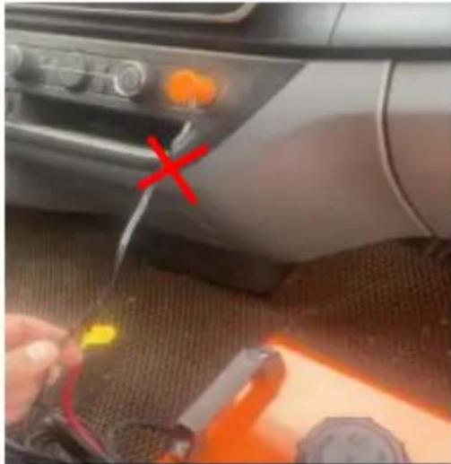
natural_image
Close-up of a car interior with a red X mark and a tool interacting with a glowing orange substance (no visible text or symbols)Cigarette lighter current low does not work
INSTALLATION DIAGRAM
CY-30/CY-32 (Verticaal type)


For specific installation, please scan the QR code to view the installation video

Waarschuwing:
Panel operation instructions
Suite 250, 9166 Anaheim Place, Rancho Cucamonga, CA 91730
| UK | REP |
YH CONSULTING LIMITED.
C/O YH Consulting Limited Office 147,
Centurion House, London Road, Staines-
upon-Thames, Surrey, TW18 4AX
| EC | REP |
E-CrossStu GmbH
Mainzer Landstr.69,
60329 Frankfurt am Main.
VEVOR®
TOUGH TOOLS, HALF PRICE
VEVOR®
TOUGH TOOLS, HALF PRICE
natural_image
Red VEVOR industrial machine with control panel and water tank (no visible text or symbols)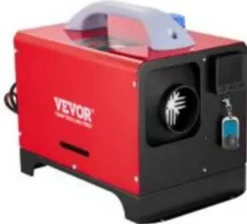
natural_image
Red and black VEVOR industrial machine with a white cover and control panel (no visible text or symbols on the device body)MODELL: CY-29 MODELL: CY-32
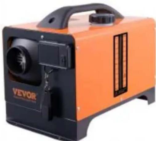
natural_image
Orange and black VEVOR portable air purifier device (no visible text or symbols on body)
natural_image
Orange VEVOR industrial machine with visible control panel and fan (no text or symbols on device body)NEED HELP? CONTACT US!
Have product questions? Need technical support? Please feel fr contact us:
Technical Support and E-Warranty Certificate www.vevor.com/support
This is the original instruction, please read all manual instruction carefully before operating. VEVOR reserves a clear interpretation user manual. The appearance of the product shall be subject to product you received. Please forgive us that we won't inform you there are any technology or software updates on our product.
Installing insulation sleeves on exhaust pipes can effectively reduce surface temperature and prevent fire hazards caused by improper installation.

natural_image
Close-up of a mechanical component with a wooden handle and green cable, no visible text or symbols
natural_image
Solid orange right-pointing arrow on white background (no text or symbols)
natural_image
Close-up of a car's side profile showing a wooden floor and a red-lit vent (no text or symbols visible)144. WARNING: Giftigt material

- On the co-driver's legroom.
- On the back wall of the cab.
- Driver's seat backrest.
- Within the tool box.

- In front of the passenger seat.
- Between the driver seat and passenger seat
- 3 & 4 under the container.
- In the trunk.

The heater is mainly installed in the passer room or baggage room of the vehicle. If it be installed, fix the heater under the unders of the vehicle, but beware of splashing.

- Inside the driver's seat.
- On the back wall of the c
- Inside the protection box.

natural_image
Orange VEVOR industrial machine with a close-up inset showing a mechanical component (no visible text or symbols)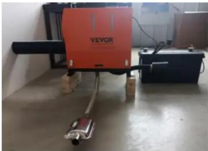
natural_image
Industrial robotic device labeled 'VEVOR' in a lab setting, with no visible text or symbols on the device itself.Inomhusinstallation Utomhusinstallationsschema
- Do not use the heater when charging the battery
- The current is low and it does not work

natural_image
Exterior view of a portable electronic device with battery, switch, and charging unit (no visible text or symbols)Suggest using energy storage (batteries) or adapters for the power supply
natural_image
Close-up of two black and red electrical wires against a light background (no text or symbols visible)natural_image
Close-up of a mechanical device with wiring and tubing, no visible text or symbolsnatural_image
Electrical wiring setup with battery, switch, and wall-mounted device (no visible text or symbols)natural_image
Interior view of a room with a battery, wiring, and wall-mounted equipment (no visible text or symbols)
natural_image
Interior view of a room with a mounted device and wiring, no visible text or symbols
natural_image
Close-up of a handheld electronic device mounted on a wall, with wires and a hand interacting near it (no visible text or symbols)Excessive pump oil produces white smoke
Blow the air gun towards the intake pip to assist combustion
Remove the oil pipe and insert it after it normal
Inspektionsdiagram
flowchart
graph TD
    A["①: Refrigerator with cooling unit"] --> B["②: Heat exchanger"]
    B --> C["③: Top-down view of turbine or fan"]
    C --> D["④: Stabilized motor with screw and shaft"]
natural_image
Black rectangular battery with two red X-shaped warning symbols on top, placed indoors (no text or labels visible)Fixing the battery clamp can easily cause poor contact
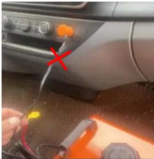
natural_image
Close-up of a car interior with a tool near the dashboard and a red X mark, no visible text or symbolsCigarette lighter current low does not work
INSTALLATION DIAGRAM
CY-30/CY-32 (Vertical typ)
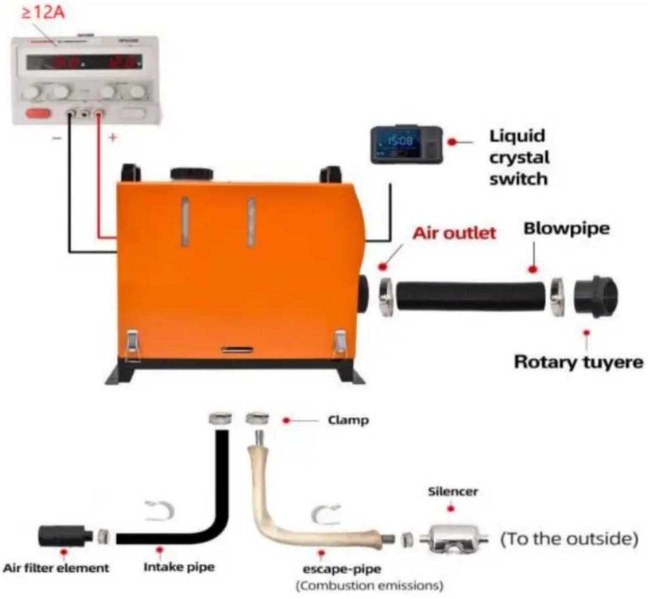

For specific installation, please scan the QR code to view the installation video

Varning:
Panel operation instructions
- Digital LCD-knapp med tre knappar [rösttyp]
C/O YH Consulting Limited Office 147, Centurion House, London Road, Staines-upon-Thames, Surrey, TW18 4AX
| EC | REP |
E-CrossStu GmbH
Mainzer Landstr.69,
60329 Frankfurt am Main.
VEVOR®
TOUGH TOOLS, HALF PRICE