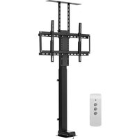
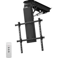
DT500-A - Flat screen mount Vevor - Free user manual and instructions
Find the device manual for free DT500-A Vevor in PDF.

| Product Type | Motorized Flat Screen Support |
| Brand | Vevor |
| Model | DT500-A |
| Maximum Load Capacity | 88 lb (40 kg) |
| Adapter Power Supply | 100-240 V~, 50/60 Hz |
| Adapter Output Voltage | 29 V DC |
| Recommended Input Current | 1.8 A |
| Motor Interface Max Output Voltage | 29 V DC |
| Motor Interface Max Output Current | 4 A |
| Operating Temperature | 0 to 40 °C |
| Operating Humidity | 20 to 90 % |
| Storage Temperature | -20 to 70 °C |
| Main Material | Steel and Plastic |
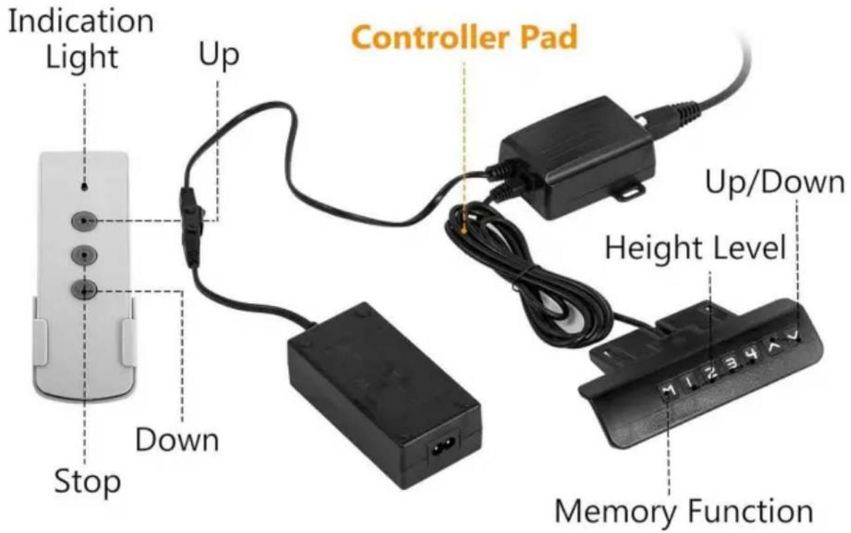
| Control Method | Wireless Remote Control and Manual Controller |
| Functions | Motorized Height Adjustment, Height Preset (4 positions), Obstacle Reversal, Reset |
| Error Display | Code Err1 for Motor Fault |
| Included Accessories | Main Body, Beams, Mounting Plates, Screws, Wall Anchors, Remote Control, Controller, Power Adapter, Power Cable |
| Mounting Specifications | Wall Mounting or Cabinet Mounting |
| Screen Compatibility | VESA Standard (holes on the back of the TV) |
| Warranty | Technical Support and Electronic Warranty Certificate (see Vevor website) |
Frequently Asked Questions - DT500-A Vevor
User questions about DT500-A Vevor
0 question about this device. Answer the ones you know or ask your own.
Ask a new question about this device
Download the instructions for your Flat screen mount in PDF format for free! Find your manual DT500-A - Vevor and take your electronic device back in hand. On this page are published all the documents necessary for the use of your device. DT500-A by Vevor.
USER MANUAL DT500-A Vevor
Technical Support and E-Warranty Certificate www. vevor. com/support
TV LIFT
USER MANUAL
MODEL: DT500-A
We continue to be committed to provide you tools with competitive price. "Save Half", "Half Price" or any other similar expressions used by us only represents an estimate of savings you might benefit from buying certain tools with us compared to the major top brands and does not necessarily mean to co all categories of tools offered by us. You are kindly reminded to verify carefully when you are placing an order with us if you are actually Saving Half in comparison with the top major brands.
MODEL: DT500-A
natural_image
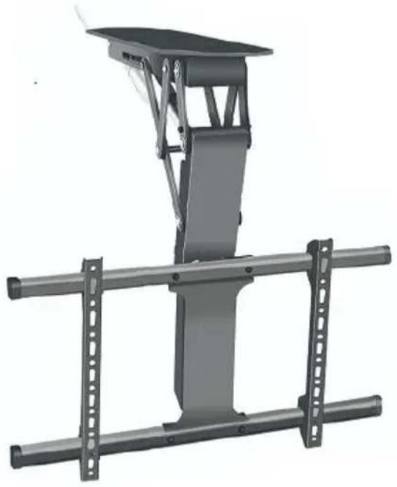
Mechanical assembly with a vertical support structure and two horizontal bars (no text or symbols visible)NEED HELP? CONTACT US!
Have product questions? Need technical support? Please feel free to contact us:
Technical Support and E-Warranty Certificate www.vevor.com/support
This is the original instruction, please read all manual instructions carefully before operating. VEVOR reserves a clear interpretation of o user manual. The appearance of the product shall be subject to the product you received. Please forgive us that we won't inform you ag there are any technology or software updates on our product.
 | Warning-To reduce the risk of injury, user must read instructions manual carefully. |
 | CORRECT DISPOSALThis product is subject to the provision of european D 2012/19/EU. The symbol showing a wheelie bin crosse through indicates that the product requires separate ret collection in the European Union. This applies to the and all accessories marked with this symbol. Products marked as such may not be discarded with normal d waste, but must be taken to acollection point for recy electrical and electronic devices. |
 | Compliance is a CE security certification. |
IMPORTANT SAFEGUARDS
Please read and understand this entire manual before attempting to assemble, operate or install the product. Fail
to follow all instructions listed below may result in electric shock, fire serious injury.
WARNING:
- The load added onto the actuator must be less than or equal to rated load of actuator.
- Please use the 29V DC power adapter.
- All actuators have duty cycle, they cannot work all the time without stopping.
- The actuator is not completely waterproof, please do not immerse water directly.
- Children shall not play with the appliance. Cleaning and user maintenance shall not be made by children without supervision.
SAVE THESE INSTRUCTIONS
ATTENTION
- Please ensure that the screws and nuts are tightened during install. For your safety, the product must be used in the specified size and limits.
- Ensure that the wall's quality and load-bearing capacity are sufficient installation. The manufacturer is not responsible for any consequences arising from improper installation.
- If installing in glass or glass curtain wall, foam brick, marble, fiber board, please consult a professional installer before installation. Otherwise the manufacturer is not responsible for any consequences caused by improper installation!
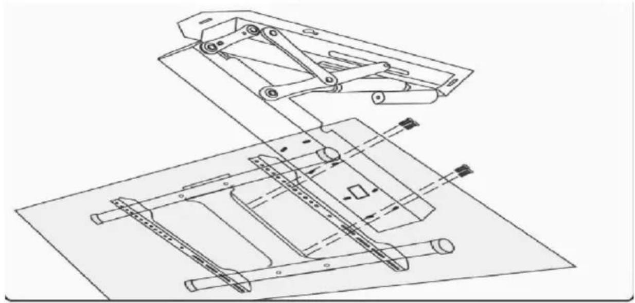
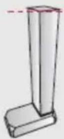
PARTS LIST
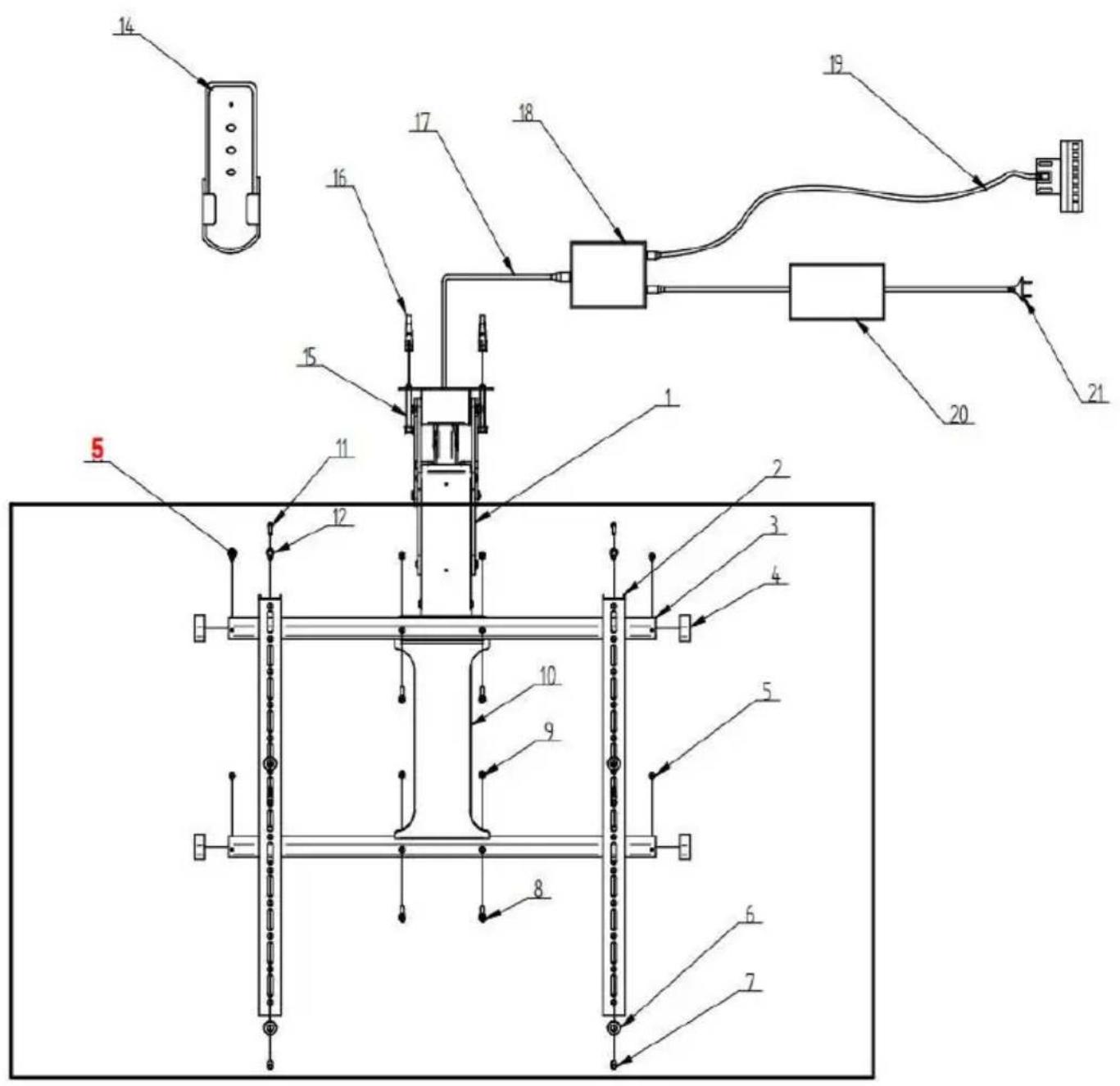
| NO. | Name | Qty | |
| 1 | Main Body Of The Support | 1 | |
| 2 | TV stand (vertical) | 2 | |
| 3 | TV stand (horizontal) | 2 | |
| 4 | Blocking Head | 4 |  |
| 5 | M5*10 | 4 | 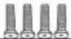 |
| 6 | 8* 16*1.7 | 4 |  |
| 7 | Cylindrical Covers | 4 | 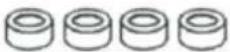 |
| 8 | M6*30 | 8 |  |
| 9 | M6 Nut | 4 |  |
| 10 | Tv Installation Panel | 1 | |
| 11 | M8*30 | 4 | 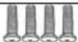 |
| 12 | M6*16 | 4 |  |
| 13 | M4*20mm | 4 |  |
| 14 | Remote Control | 1 | [yzcc] |
| 15 | M7*60 | 6 |  |
| 16 | 7 × 10 × 60mm | 6 | 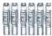 |
| 17 | Border Line | 1 | |
| 18 | Controller | 1 | 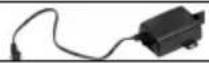 |
| 19 | Manual Control Wire | 1 | 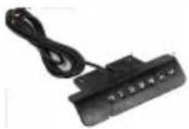 |
| 20 | Power Adapter | 1 | 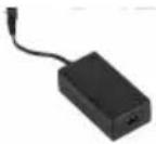 |
| 21 | Power Cord | 1 | 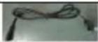 |
INSTRUCTIONS
STEP 1 Power on the main body of the support and adjust open. Use a screwdriver to remove the four inner fixing screw detach the front connecting plate. Keep the screws as spares
STEP 2
Position the support wall plate, mark the hole locations, and holes. Insert the expansion tubes into the holes, and insert the expansion screw through the wall plate to fix the main body support.
Installation tips:
Screw the expansion screws into the left and right gourd holes about halfway (1/2), then position the support body over the screws through the large hole in the gourd.
Temporarily suspend the support by aligning it with the empty hole post Next, insert the expansion screws the remaining four positions. Finally tighten all the expansion screws to complete the installation, making the process easier.

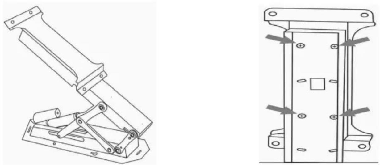
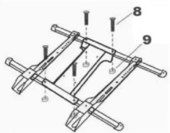
STEP 3
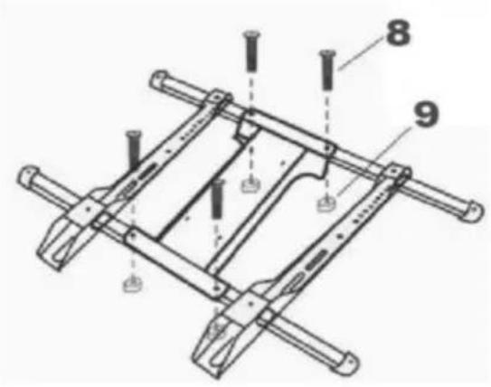
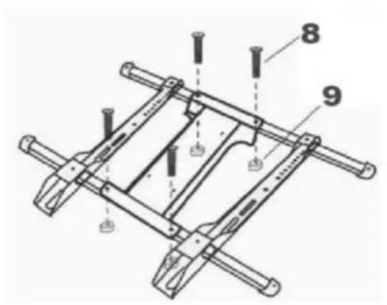
① Insert the two beams into the two holes on the upper and sides of the hook, and install and fix the plugs at both end beams by screws.
② Connect the upper and lower four holes of the mounting the four middle holes of the beam through bolts and nuts.

STEP 4
Connected TV
① Select the appropriate holes for the two vertical hooks of assembled tic-tac-stand, and connect the tic-tac-stand with the on the back of the TV.
② Install the safety screws above and below the two hooks respectively.
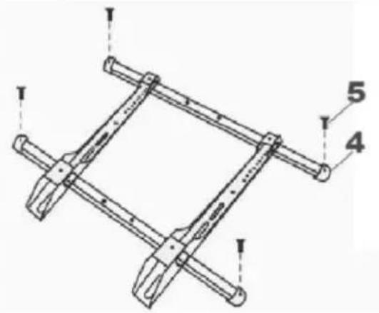
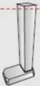
STEP 5
Install TV
As shown in the figure: Connect the 4 holes of the connect connected to the TV and the holes at the front end of the through the spare screws removed in step 1.
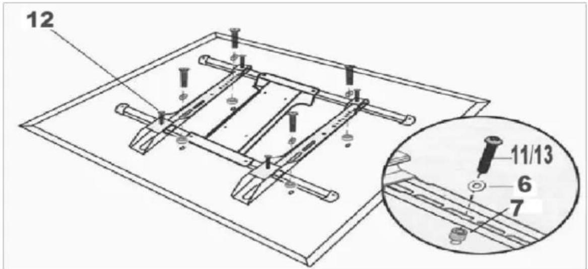
natural_image
Technical line drawing of a mechanical assembly with exploded and assembled views (no text or symbols)STEP 7
Connection adapter

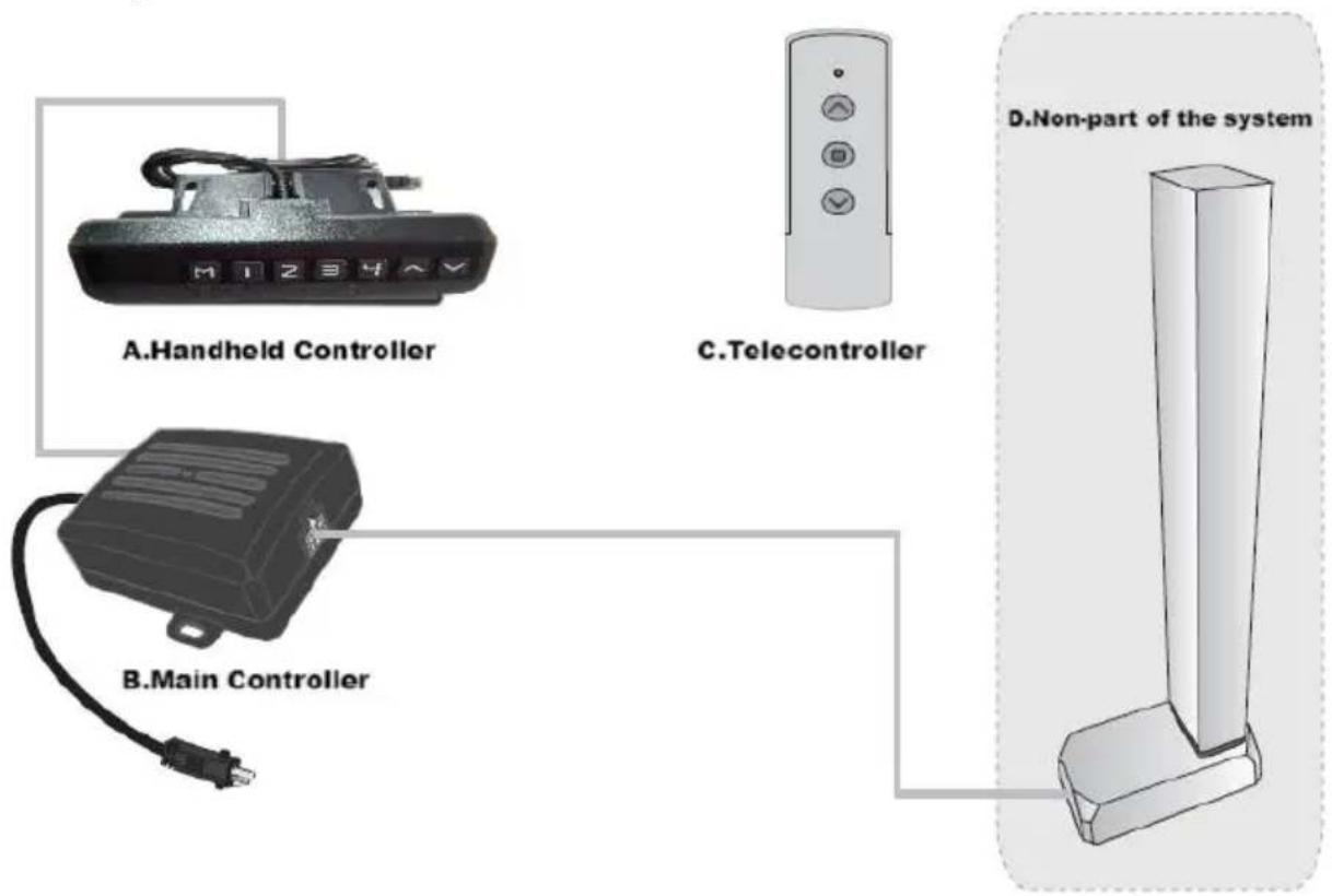
I. Function introduction
Intelligent single column controller has the following characteristics:
- It can control two motors' output to achieve synchronous operation
- Indicator light displays the fault, resetting;
- Controlled by up and down buttons;
- Wireless remote control(alternative).
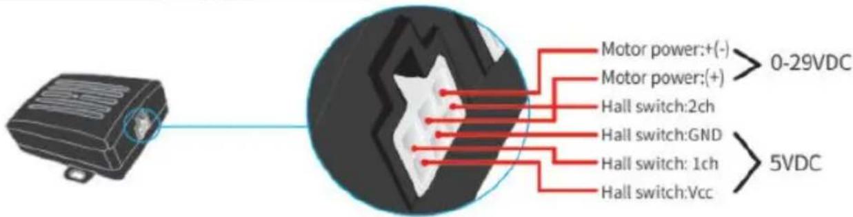
II. System parameters
1.Input voltage:DC29V;
2.Input current: recommending above 1.8A and according to the load;
3.Maximum output voltage of mo interface:DC29V;
4.Maximum output current of mot interface:4A;
5.Operating temperature:0\~40℃
6. Working humidity:20\~90%;
7. Storage temperature:20\~70°C.
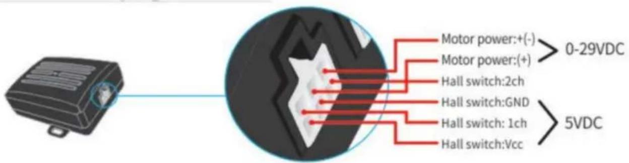
III. System connection
IV. Motor interfase plug definition:
V. Fault code and its treatment
| 1.Fault code Err1 | 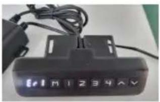 |
| When the manual controller shows Er1, it's a faErr1. It means there is something wrong withinterface channel (see the following picture). Fofexemple motors are not connected in a positiveHall signal board is not connected; Paper line, | 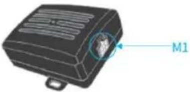 |
| After the issue is resolved, press the 'down' butmore than 3 seconds to clear the fault, andmachine will return to reset state. | 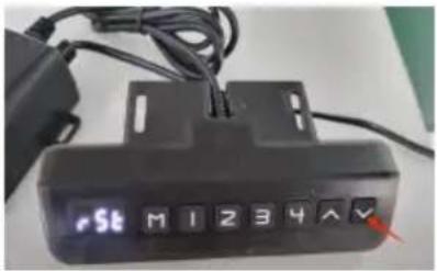 |
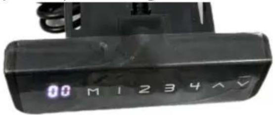
VI. System reset
| 1.Prompt resetWhen the manual controller indicator light always (see the following picture),it means the system resetting. The whole system needs to reset mau | 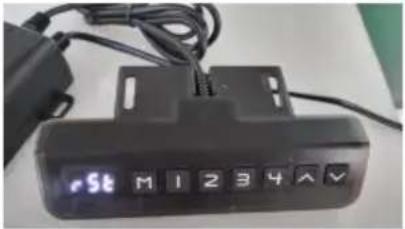 |
| 2.Line resetWhen the manual controller shows the minimum heigh ,pressing "down" button more than 5 sec and the indicator light is on. It means reseti | 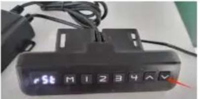 |
| 3.Releasing the hand and starting to reset system,after the manual controller indicator light i |  |
| 4.Reset methodWhen the manual controller indicator light alwa stays on (see the following figure), pressing the button and do not release it. | 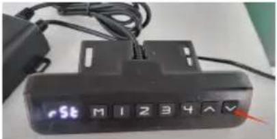 |
| The column may begin to shorten, and the speed could slow down. Of any other damage during operation; if there is any, stop immediately. | |
 | |
The column will rise 5\~10mm after a short time when it reach point.
After all arrive, rising a small distance.
When the manual controller indicator light is off(see the following picture), releasing the hand and end at resetting.
VII.Preset target height
| 1.Preset target height quantity:The system provides 4 groups of preset height storage | |
| 2.Preset target height data erasure:The erasing function is not configured separately. When a new pa is set, the system automatically erases the old parameter. | |
| 3.Preset target height operation method:At any height (reset state, cannot perform this operation in error current height parameter can be preset to keys 1-4. | |
| Example: 1Set the current height 56 to key No. | 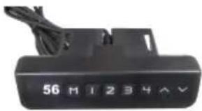 |
| 2Press the "M" key to display "SET" | 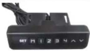 |
| 3Within 2 seconds, press "2" before "SET" disapp | 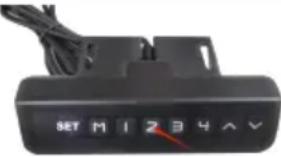 |
| 4The "S-2" preset is displayed. End, the previous display is restored. | 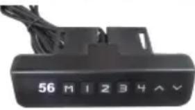 |
| 5. Use the method of preset target height:At any height (reset state, cannot perform this operation in the w state), you can use keys 1-4 to quickly reach the preset target current height is already near the preset target height, no action performed. | |
VIII. Telecontroller operation
| 1. Matching window periodMatching window period is repowering after 3 seconds.There will be buzzing sound when the period ends. |
| 2. Right codeIn matching window period, passing the "up button"longly and waiting long and 3 short intervals of buzzing sound, it means righting code |
IX. Backtracking when encountering obstacles
In addition to the reset state, when working, the mechanical structure encounter a sudden changes from loading, which will cause the operation to carry out a fallback operation to prevent external sound of injury.
PRODUCT PARAMETERS
| Model | Safe Loading Weight | Input | Adapter input voltage | Region | |
| 1 | DT500-A | 88lbs | DC29V 1.8A | 100-240V~50/60Hz | America |
| 2 | Europe |
VEVOR®
TOUGH TOOLS, HALF PRICE
Technical Support and E-Warranty Certificate www. vevor. com/support
VEVOR®
TOUGH TOOLS, HALF PRICE
natural_image
Mechanical support structure with metal frame and support beams (no text or symbols)BESOIN D'AIDE ? CONTACTEZ-NOUS !
www.vevor.com/support
natural_image
Technical line drawing of a mechanical lever assembly (no text or symbols)
natural_image
Technical line drawing of a mechanical assembly with mounting holes and directional arrows (no text or symbols)ÉTAPE 2

ÉTAPE 4
ÉTAPE 5
natural_image
Technical line drawing of a mechanical assembly with exploded and assembled views (no text or symbols)ÉTAPE 7
After all arrive, rising a small distance.

PARAMÈTRES DUPRODUIT
natural_image
Mechanical support structure with metal frame and support beams (no text or symbols)natural_image
Technical line drawing of a mechanical lever assembly (no text or symbols)
natural_image
Technical line drawing of a mechanical component with mounting holes and mounting brackets (no text or symbols)SCHRITT 2
SCHRITT 4
Connected TV
SCHRITT 5
natural_image
Technical line drawing of a mechanical assembly with exploded and assembled views (no text or symbols)SCHRITT 7
Anschlussadapter

Column began to shorten, when resetting.
After all arrive, rising a small distance.
natural_image
Mechanical support structure with metal frame and support beams (no text or symbols visible)natural_image
Technical line drawing of a mechanical lever assembly (no text or symbols)
natural_image
Technical line drawing of a mechanical bracket with mounting holes and mounting points (no text or symbols)PASSO 2

PASSO 4
TV connessa
PASSO 5
Installare la TV
natural_image
Technical line drawing of a mechanical assembly with no visible text or symbolsPASSO 7
After all arrive, rising a small distance.

natural_image
Mechanical support structure with metal frame and support beams (no text or symbols visible)natural_image
Technical line drawing of a mechanical lever assembly (no text or symbols)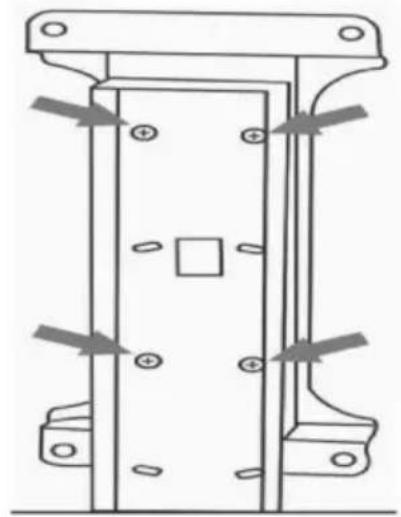
natural_image
Technical line drawing of a mechanical assembly with mounting holes and directional arrows (no text or symbols)PASO 2

PASO 4
PASO 5
Instalar TV
natural_image
Technical line drawing of a mechanical assembly with exploded and assembled views (no text or symbols)PASO 7
After all arrive, rising a small distance.

VII. Altura del objetivøpreestablecida
natural_image
Mechanical support structure with metal frame and support beams (no text or symbols)POTRZEBUJESZ POMOCY? SKONTAKTUJ SIĘ Z NAMI!
natural_image
Technical line drawing of a mechanical lever assembly (no text or symbols)
natural_image
Technical line drawing of a mechanical assembly with mounting holes and directional arrows (no text or symbols)KROK 2
KROK 5
Zainstaluj telewizor
natural_image
Technical line drawing of a mechanical assembly with exploded and assembled views (no text or symbols)KROK 7
After all arrive, rising a small distance.

natural_image
Mechanical support structure with metal frame and support beams (no text or symbols visible)HULP NODIG? NEEM CONTACT MET ONS OP!
| NEE. | Naam | Aantal | |
| 1 | Hoofdgedeelte van deondersteuning | 1 | |
| 2 TV-standaard (verticaal) | 2 | ||
| 3 TV-standaard (horizontaal)4 | 2 | ||
| Blokkerende kop | 4 |  | |
| 5 M5*10 | 4 |  | |
| 6 8^*16^*1,7 | 4 |  | |
| 7 | Cilindrische deksels | 4 |  |
| 8 M6*30 | 8 |  | |
| 9 M6 Moer | 4 |  | |
| 10 Tv-installatiepaneel | 1 | ||
| 11 M8*30 | 4 | 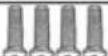 | |
| 12 M6*16 | 4 |  | |
| 13 M4*20mm | 4 |  | |
| 14 Afstandsbediening | 1 | [BAKT] | |
| 15 M7*60 | 6 |  | |
| 16 7 x 10 x 60 mm | 6 | 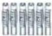 | |
| 17 Grenslijn | 1 | ||
| 18 Controller | 1 | 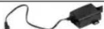 | |
| 19 Handmatige besturingsdraad | 1 | 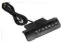 | |
| 20 Stroomadapter | 1 | 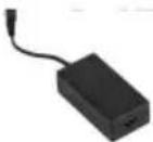 | |
| 21 Netsnoer | 1 | 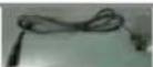 | |
INSTRUCTIES
natural_image
Technical line drawing of a mechanical lever assembly (no text or symbols)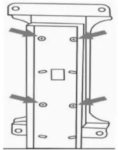
natural_image
Technical line drawing of a mechanical assembly with mounting holes and internal components (no text or symbols)STAP 2
STAP 4
Verbonden tv
STAP 5
TV installeren
natural_image
Technical line drawing of a mechanical assembly with exploded and assembled views (no text or symbols)STAP 7
Aansluitadapter
IV. Definitie varmotorinterfaceplug:
V. Foutcode en de behandeling ervan
Column began to shorten, when resetting.
After all arrive, rising a small distance.

natural_image
Mechanical support structure with metal frame and support beams (no text or symbols)BEHÖVER DU HJÄLP? KONTAKTA OSS!
natural_image
Technical line drawing of a mechanical lever assembly (no text or symbols)
natural_image
Technical line drawing of a mechanical assembly with mounting holes and structural elements (no text or symbols)STEG 2
STEG 4
Ansluten TV
STEG 5
Installera TV:n
natural_image
Technical line drawing of a mechanical assembly with exploded and assembled views (no text or symbols)STEG 7
Anslutningsadapter

After all arrive, rising a small distance.
www.vevor.com/support