RLLF5 - Flat screen mount Vevor - Free user manual and instructions
Find the device manual for free RLLF5 Vevor in PDF.

User questions about RLLF5 Vevor
0 question about this device. Answer the ones you know or ask your own.
Ask a new question about this device
Download the instructions for your Flat screen mount in PDF format for free! Find your manual RLLF5 - Vevor and take your electronic device back in hand. On this page are published all the documents necessary for the use of your device. RLLF5 by Vevor.
USER MANUAL RLLF5 Vevor
Technical Support and E-Warranty Certificate www.vevor.com/support
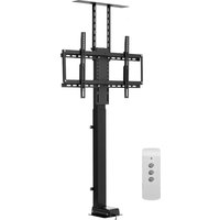
TV WALL MOUNTS
USER MANUAL
MODEL:RLLF5
We continue to be committed to provide you tools with competitive price. "Save Half, "Half Price" or any other similar expressions used by us only represents an estimate of savings you might benefit from buying certain tools with us compared to the major top brands and doses not necessarily mean to cover all categories of tools offered by us. You are kindly reminded to verify carefully when you are placing an order with us if you are actually saving half in comparison with the top major brands.
VEVOR®
TOUGH TOOLS, HALF PRICE
TV WALL MOUNTS
MODEL:RLLF5
natural_image
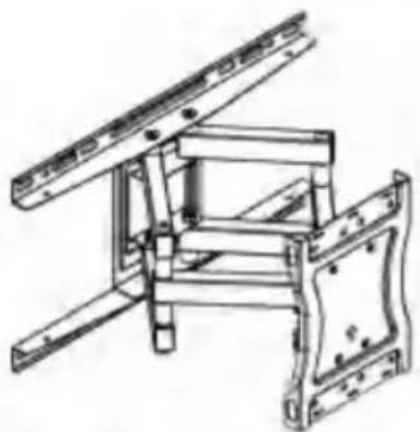
Technical line drawing of a mechanical assembly with mounting brackets and structural supports (no text or symbols)NEED HELP? CONTACT US!
Have product questions? Need technical support? Please feel free to contact us:
O CustomerService@vevor.com
This is the original instruction, please read all manual instructions carefully before operating. VEVOR reserves a clear interpretation of our user manual. The appearance of the product shall be subject to the product you received. Please forgive us that we won't inform you again if there are any technology or software updates on our product.
WARNING:
Read this material before using this product Failure to do so can result in serious injury.
Assembly precautions
- Assemble only according to these instructions. Improper assembly can create hazards. This product is designed for use in wood stud and solid concrete wall. -Do not mount on dry wall alone.
- Wear ANSI-approved safety goggles and heavy-duty work gloves during assembly.
- Keep the assembly area clean and well-lit.
- Keep bystanders out of the area during assembly.
- Do not assemble when tired or when under the influence of alcohol, drugs or medication.
- The product capabilities apply to properly and completely assembled products only.
- For additional information regarding the parts listed in the following pages, please refer to the Assembly Diagram of this manual. Unwrap and separate all parts in a clean work area.
Use precautions
- Weight Restrictions: Do not exceed the maximum weight capacity of this product.
- The wall must be capable of supporting five times the weight of the TV and mount combined.
- Do not use this product for any purpose not explicitly specified by manufacture. Manufacture is not responsible for damage or injury caused by incorrect assembly or use.
- Inspect before every use; do not use if parts are loose or damaged.
SAVE THIS MANUAL
TOOLS NEEDED
Stud Finder

(5.5 mm)
Wood Drill
Tape Measure
Hammer
Pencil
Screwdriver
Dnll
Socket Wrench
3/8 in.
(10 mm)
Concrete Drill
Level
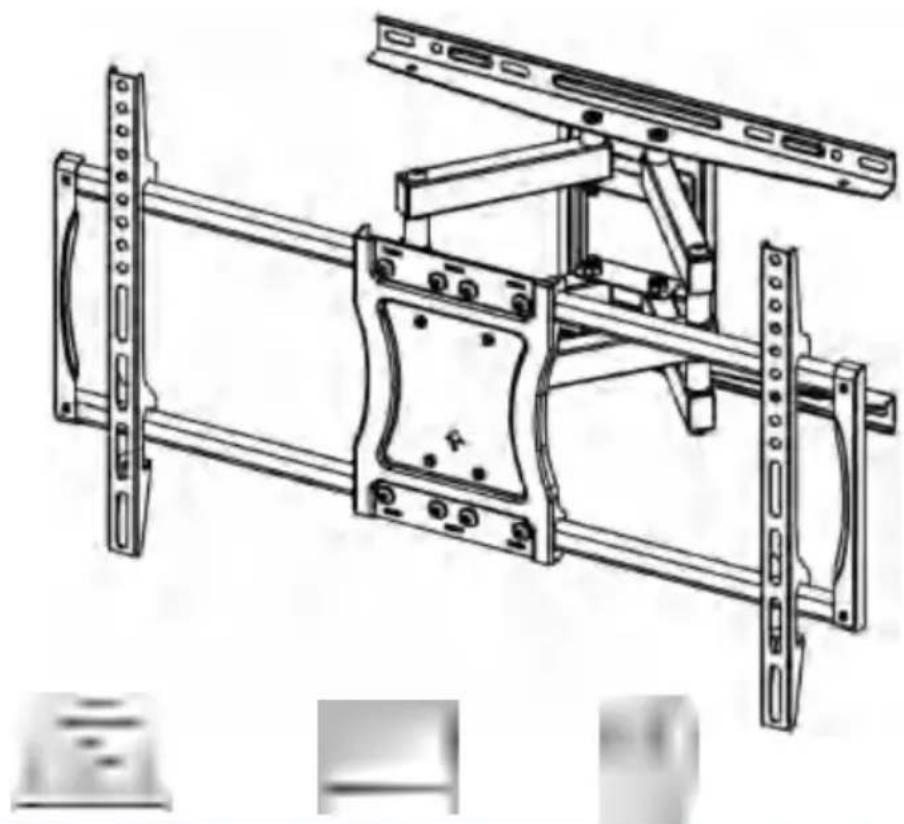
HARDWARE INCLUDED
natural_image
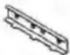
Technical line drawing of a mechanical frame assembly (no text or symbols)10^x1 Wall Hate
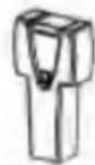
natural_image
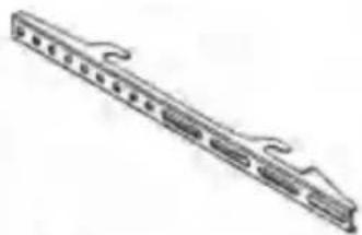
Technical line drawing of a mechanical component with multiple slots and curved extensions (no text or symbols)02 × 2 TV Brackets
(2^ x 2 Pressing Plate
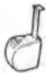
natural_image
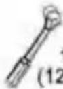
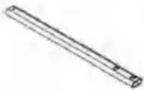
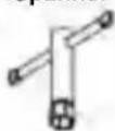
Simple line drawing of a cylindrical object with a protruding rod (no text or symbols)03 ×4 Extension Arms
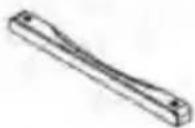
05 X 2 Supporting Bar
TV Screws / Washers
M4X12m<n
伊


④X4
6x4
M4-6-8
•M«X2H«n 1ST aX65mm|
③又4

命8mm

M6X30mm
MBX15mm
伊
MfIX45nwn 5mm
⑥x4 ⑤x4
Wall Anchor
⑥X4 ⑥x8
M4X8mm
6X8
仁WST

MBX20mm

Socket Spanner
10mm

Allan Key
0X4 10X4
0x8 <§>X1
⑥X1
STEP1 Attach Brackets to TV
STEP 1-1 Measure TV Hole Pattern
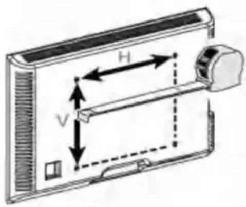
Note: VESA=Horizontal x Vertical (Max VESA:600x400mm)
100mm 4 in
200mm 7 7/8 in
300mm 11 3/4 in
400mm 153/4in
600mm 23 5/8 in
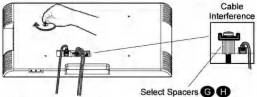
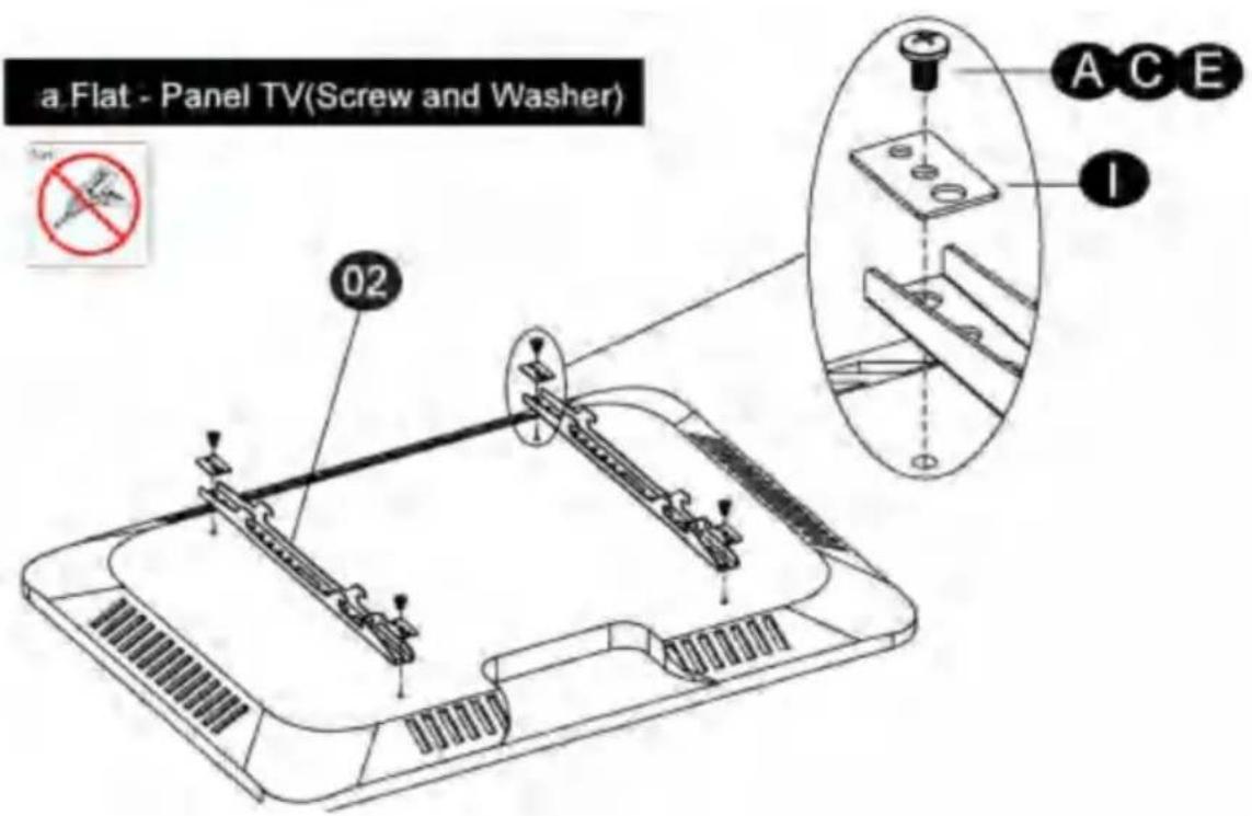
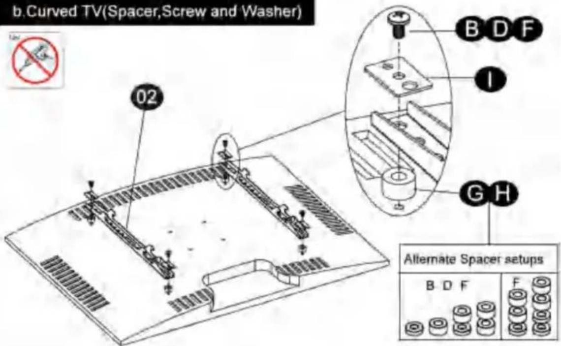
STEP 1-2 Select TV Screws
Preparation: Check VESA pattern of TV before installation. Only one screw size fits your TV.
STEP 1-3 Attach the TV Brackets
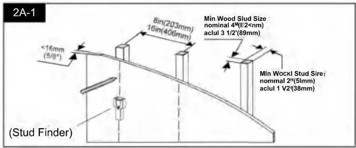
STEP 2 Attach Wall Plate to Wall
STEP 2A Wood Stud Installation
STEP 2B Solid □oncrete Wall Installation
 ☐aution: These anchors are for solid concrete and concrete block walls ☐NLY D☐ N☐T use them in drywall or wood studs.     STEP 3 Extension Arms Assembly   STEP 4 Hang and Secure TV to Wall Plate  STEP 5 TV Leveling Adjustments (±3。)  STEP 6 Tilting angle adjustments (+15°\~15°) PRODUCT PARAMETER
| Model | RLLF5 |
| Safe Loading Weight | 60 kg |
| Product Size 430*240*80 mm | |
| Net Weight 5.75 kg |
VEVOR®
TOUGH TOOLS, HALF PRICE Technical Support and E-Warranty Certificate www.vevor.com/supportETVRME
® TOUG H À RICO, HALF P Assistance technique et certificat de garantie électronique www.vevor.com/support SUPPORTS MURAUX POUR TÉLÉVISEUR MANUEL D'UTILISATION MODÈLE : RLLF5 Nous continuons à nous engager à vous fournir des outils à des prix compétitifs. « Économisez la moitié », « Moitié prix » ou toute autre expression similaire utilisée par nous ne représente qu'une estimation des économies que vous pourriez réaliser en achetant certains outils chez nous par rapport aux grandes marques et ne couvre pas nécessairement toutes les catégories d'outils que nous proposons. Nous vous rappelons de bien vouloir vérifier attentivement lorsque vous passez une commande chez nous si vous économisez réellement la moitié par rapport aux grandes marques.V R#t LE
 SUPPORTS MURAUX POUR TÉLÉVISEUR TOUG H TROP LS, HA LF PRI CE MODÈLE : RLLF5 natural_image
Technical line drawing of a mechanical assembly with mounting brackets and structural supports (no text or symbols)CONSIGNES DE SÉCURITÉ
AVERTISSEMENT:
Lisez ce document avant d'utiliser ce produit. Le non-respect de cette consigne peut entraîner des blessures graves.Précautions d'assemblage 1.
Assembler uniquement selon ces instructions. Un assemblage incorrect peut créer des dangers. Ce produit est conçu pour être utilisé dans des murs à ossature de bois et des murs en béton massif. - Ne pas monter sur une cloison sèche uniquement. 2. Portez des lunettes de sécurité approuvées par l'ANSI et des gants de travail robustes pendant assemblée. 3. Gardez la zone de montage propre et bien éclairée. 4. Gardez les spectateurs hors de la zone pendant le montage. 5. Ne vous réunissez pas lorsque vous êtes fatigué ou sous l'influence de l'alcool, de drogues ou des médicaments. 6. Les capacités du produit s'appliquent aux produits correctement et complètement assemblés. produits uniquement. 7. Pour plus d'informations sur les pièces répertoriées dans les pages suivantes, Veuillez vous référer au schéma d'assemblage de ce manuel. Déballez et séparez toutes les pièces dans une zone de travail propre.Précautions d'utilisation
1. Restrictions de poids : Ne pas dépasser la capacité de poids maximale de cet produit. 2. Le mur doit être capable de supporter cinq fois le poids du téléviseur et du support combinés. 3. N'utilisez pas ce produit à des fins non explicitement spécifiées par Fabrication. Le fabricant n'est pas responsable des dommages ou blessures causés par un assemblage ou une utilisation incorrects. 4. Inspectez avant chaque utilisation ; ne pas utiliser si des pièces sont desserrées ou endommagées.CONSERVER CE MANUEL
OUTILS NÉCESSAIRES
 Stud Finder  7/32 in. (5.5 mm) Wood Drill  Tape Measure  Hammer  Pencil  Screwdriver  Dnll  Socket Wrench  3/8 in. (10 mm) Concrete Drill  LevelMATÉRIEL INCLUS
natural_image
Technical line drawing of a mechanical frame assembly (no text or symbols)natural_image
Technical line drawing of a mechanical part with evenly spaced holes and mounting brackets (no text or symbols)natural_image
Simple line drawing of a cylindrical object with a flanged end (no text or symbols)Vis/Rondelles TV
M4X12mÉTAPE D'ASSEMBLAGE
STEP1 Attach Brackets to TV
STEP 1-1 Measure TV Hole Pattern
 Note: VESA=Horizontal x Vertical (Max VESA:600x400mm) 100mm 4 in 200mm 7 7/8 in 300mm 11 3/4 in 400mm 153/4in 600mm 23 5/8 inSTEP 1-2 Select TV Screws
Preparation: Check VESA pattern of TV before installation. Only one screw size fits your TV.      ÉTAPE 1-3 Fixez les supports du téléviseur   ÉTAPE 2 Fixez la plaque murale au mur
ÉTAPE 2A Installation de montants en bois   ÉTAPE 2B Installation d'un mur en béton massif  Attention : ces ancrages sont destinés aux murs en béton massif et en parpaings NE LES UTILISEZ PAS UNIQUEMENT dans des cloisons sèches ou des montants en bois.     ÉTAPE 3 Assemblage des bras d'extension   STEP 4 Hang and Secure TV to Wall Plate  ÉTAPE 5 Réglages de mise à niveau du téléviseur (±3 )  STEP 6 Tilting angle adjustments (+15°\~15°) PARAMÈTRE DU PRODUIT
| Modèle | RLLF5 |
| Poids de chargement sécuritaire | 60 kg |
| Taille du produit | 430*240*80 mm |
| Poids net | 5,75 kg |
VEVOR
OUTILS ROBUSTES, MOITIÉ PRIX Assistance technique et certificat de garantie électronique www.vevor.com/support ®UND VVDER R ^®
OLS, HALF PREISH ZUTOUG
Technischer Support und E-Garantie-Zertifikat www.vevor.com/supportTV-WANDHALTERUNGEN
BENUTZERHANDBUCH
MODELL:RLLF5 Wir sind weiterhin bestrebt, Ihnen Werkzeuge zu wettbewerbsfähigen Preisen anzubieten. „Sparen Sie die Hälfte“, „Halber Preis“ oder andere ähnliche Ausdrücke, die wir verwenden, stellen lediglich eine Schätzung der Ersparnis dar, die Sie beim Kauf bestimmter Werkzeuge bei uns im Vergleich zu den großen Topmarken erzielen können, und bedeuten nicht notwendigerweise, dass sie alle von uns angebotenen Werkzeugkategorien abdecken. Wir möchten Sie freundlich daran erinnern, bei Ihrer Bestellung bei uns sorgfältig zu prüfen, ob Sie im Vergleich zu den großen Topmarken tatsächlich die Hälfte sparen.VVUND DER R®
H AUCH DASTQUGF PRI TV-WANDHALTERUNGEN MODELL:RLLF5 natural_image
Technical line drawing of a mechanical assembly with mounting brackets and structural supports (no text or symbols)SICHERHEITSHINWEISE
WARNUNG:
Lesen Sie dieses Material, bevor Sie dieses Produkt verwenden. Andernfalls kann es zu schweren Verletzungen kommen.Vorsichtsmaßnahmen bei der
Montage 1. Montieren Sie das Produkt ausschließlich gemäß dieser Anleitung. Eine unsachgemäße Montage kann Gefahren verursachen. Dieses Produkt ist für die Verwendung in Holzpfosten und Massivbetonwänden konzipiert. - Nicht ausschließlich an Trockenbauwänden montieren. 2. Tragen Sie ANSI-zugelassene Schutzbrillen und schwere Arbeitshandschuhe während Montage. 3. Halten Sie den Versammlungsbereich sauber und gut beleuchtet. 4. Halten Sie während der Montage unbeteiligte Zuschauer vom Bereich fern. 5. Montieren Sie nicht, wenn Sie müde sind oder unter dem Einfluss von Alkohol, Drogen oder oder Medikamente. 6. Die Produkteigenschaften gelten für ordnungsgemäß und vollständig montierte Nur Produkte. 7. Weitere Informationen zu den auf den folgenden Seiten aufgeführten Teilen erhalten Sie Bitte beachten Sie das Montagediagramm in diesem Handbuch. Packen Sie alle Teile in einem sauberen Arbeitsbereich aus und trennen Sie sie.Vorsichtsmaßnahmen
1. Gewichtsbeschränkungen: Überschreiten Sie nicht die maximale Gewichtskapazität dieses Produkt. 2. Die Wand muss das Fünffache des Gesamtgewichts von Fernseher und Halterung tragen können. 3. Verwenden Sie dieses Produkt nicht für Zwecke, die nicht ausdrücklich von Der Hersteller ist nicht für Schäden oder Verletzungen verantwortlich, die durch falsche Montage oder Verwendung entstehen. 4. Vor jedem Gebrauch prüfen; nicht verwenden, wenn Teile lose oder beschädigt sind. BEWAHREN SIE DIESES HANDBUCH AUFBENÖTIGTE WERKZEUGE
 Stud Finder  7/32 in. (5.5 mm) Wood Drill  Tape Measure  Hammer  Pencil  Screwdriver  Dnll  Socket Wrench  3/8 in. (10 mm) Concrete Drill  LevelHARDWARE INKLUSIVE
natural_image
Technical line drawing of a mechanical frame assembly (no text or symbols)natural_image
Technical line drawing of a mechanical component with multiple slots and mounting holes (no text or symbols)natural_image
Simple line drawing of a cylindrical object with a flanged end (no text or symbols)TV Schrauben / Unterlegscheiben
M4X12mMONTAGESTRITT
STEP1 Attach Brackets to TV
STEP 1-1 Measure TV Hole Pattern  Note: VESA=Horizontal x Vertical (Max VESA:600x400mm) 100mm 4 in 200mm 7 7/8 in 300mm 11 3/4 in 400mm 153/4in 600mm 235/8 inSTEP 1-2 Select TV Screws
Preparation: Check VESA pattern of TV before installation. Only one screw size fits your TV.      SCHRITT 1-3 Befestigen Sie die TV-Halterungen   SCHRITT 2 Wandplatte an der Wand befestigen
SCHRITT 2A Installation der Holzpfosten
 SCHRITT 2B Installation einer Massivbetonwand
 Achtung: Diese Anker sind für Massivbeton- und Betonsteinwände Verwenden Sie sie NUR NICHT in Trockenbauwänden oder Holzpfosten.     SCHRITT 3 Montage der Verlängerungsarme   STEP 4 Hang and Secure TV to Wall Plate  SCHRITT 5: Nivellierung des Fernsehgeräts (±3 Zoll)  STEP 6 Tilting angle adjustments (+15°\~15°) PRODUKTPARAMETER
| Modell | RLLF5 |
| Sicheres Ladegewicht | 60 kg |
| Produktgröße | 430*240*80 mm |
| Nettogewicht | 5,75 kg |
VEVOR
ROBUSTE WERKZEUGE ZUM HALBEN PREIS Technischer Support und E-Garantie-Zertifikat www.vevor.com/support ®VEVILR®
OLS, HALF PRISOH ATOCCARE
Supporto tecnico e certificato di garanzia elettronica www.vevor.com/supportSUPPORTI TV DA PARETE
MANUALE D'USO
MODELLO:RLLF5 Continuiamo a impegnarci per fornirvi strumenti a prezzi competitivi. "Risparmia la metà", "Metà prezzo" o qualsiasi altra espressione simile da noi utilizzata rappresenta solo una stima del risparmio che potresti ottenere acquistando determinati strumenti con noi rispetto ai principali marchi principali e non significa necessariamente coprire tutte le categorie di strumenti da noi offerti. Ti ricordiamo gentilmente di verificare attentamente quando effettui un ordine con noi se stai effettivamente risparmiando la metà rispetto ai principali marchi principali.VEVILR®
TOCCAREAnche ioLS, HA LF PRI QUESTO SUPPORTI TV DA PARETEMODELLO:RLLF5
natural_image
Technical line drawing of a mechanical assembly with mounting brackets and structural supports (no text or symbols)HAI BISOGNO DI AIUTO? CONTATTACI!
Hai domande sul prodotto? Hai bisogno di supporto tecnico? Non esitare a contattarci contattaci:CustomerService@vevor.com
Questa è l'istruzione originale, si prega di leggere attentamente tutte le istruzioni del manuale prima di utilizzare. VEVOR si riserva una chiara interpretazione del nostro manuale utente. L'aspetto del prodotto sarà soggetto al prodotto ricevuto. Vi preghiamo di perdonarci se non vi informeremo di nuovo se ci sono aggiornamenti tecnologici o software sul nostro prodotto.ISTRUZIONI DI SICUREZZA
AVVERTIMENTO:
Leggere attentamente il presente materiale prima di utilizzare il prodotto. La mancata osservanza di questa precauzione può causare gravi lesioni.Precauzioni di montaggio 1.
Montare solo secondo queste istruzioni. Un montaggio non corretto può creare pericoli. Questo prodotto è progettato per l'uso in montanti in legno e pareti in cemento armato. -Non montare solo su pareti in cartongesso. 2. Indossare occhiali di sicurezza approvati ANSI e guanti da lavoro resistenti durante assemblaggio. 3. Mantenere l'area di assemblaggio pulita e ben illuminata. 4. Tenere gli astanti fuori dall'area durante l'assemblea. 5. Non riunirsi quando si è stanchi o sotto l'effetto di alcol, droghe o farmaci. 6. Le capacità del prodotto si applicano a prodotti correttamente e completamente assemblati solo prodotti. 7. Per ulteriori informazioni sulle parti elencate nelle pagine seguenti, fare riferimento allo schema di montaggio di questo manuale. Disimballare e separare tutte le parti in un'area di lavoro pulita.Precauzioni d'uso 1.
Limitazioni di peso: non superare la capacità di peso massima di questo prodotto. 2. La parete deve essere in grado di sostenere cinque volte il peso del televisore e del supporto messi insieme. 3. Non utilizzare questo prodotto per scopi non esplicitamente specificati da fabbricazione. La fabbricazione non è responsabile per danni o lesioni causati da un montaggio o un utilizzo non corretti. 4. Ispezionare prima di ogni utilizzo; non utilizzare se alcune parti sono allentate o danneggiate.SALVA QUESTO MANUALE
STRUMENTI NECESSARI
 Stud Finder  7/32 in. (5.5 mm) Wood Drill  Tape Measure  Hammer  Pencil  Screwdriver  Dnll  Socket Wrench  3/8 in. (10 mm) Concrete Drill  LevelHARDWARE INCLUSO
natural_image
Technical line drawing of a mechanical frame assembly (no text or symbols)natural_image
Technical line drawing of a mechanical component with multiple slots and mounting holes (no text or symbols)natural_image
Simple line drawing of a cylindrical object with a flanged end (no text or symbols)Viti/Rondelle TV
M4XI2mFASE DI MONTAGGIO
STEP1 Attach Brackets to TV
STEP 1-1 Measure TV Hole Pattern
 Note: VESA=Horizontal x Vertical (Max VESA:600x400mm) 100mm 4 in 200mm 7 7/8 in 300mm 11 3/4 in 400mm 153/4in 600mm 235/8 inSTEP 1-2 Select TV Screws
Preparation: Check VESA pattern of TV before installation. Only one screw size fits your TV.      FASE 1-3 Fissare le staffe TV   FASE 2 Fissare la piastra a muro al muro
FASE 2A Installazione del montante in legno   FASE 2B Installazione di un muro di cemento solido  Attenzione: questi ancoraggi sono adatti per muri in calcestruzzo e blocchi di calcestruzzo. NON utilizzarli su cartongesso o montanti in legno.     FASE 3 Assemblaggio dei bracci di estensione   STEP 4 Hang and Secure TV to Wall Plate  FASE 5 Regolazioni del livellamento della TV ÿ±3ÿÿ  STEP 6 Tilting angle adjustments (+15°\~15°) PARAMETRO PRODOTTO
| Modello | RLLF5 |
| Peso di carico sicuro | 60 chili |
| Dimensioni del prodotto | 430*240*80 millimetri |
| Peso netto | 5,75 kg |
VEVORE
UTENSILI RESISTENTI, A METÀ PREZZO Supporto tecnico e certificato di garanzia elettronica www.vevor.com/supportV Y V ELR ^®
H ATOLSO, HARLOZ P
Soporte técnico y certificado de garantía electrónica www.vevor.com/support SOPORTES DE PARED PARA TV MANUAL DEL USUARIO MODELO: RLLF5 Seguimos comprometidos a brindarle herramientas a precios competitivos. "Ahorre la mitad", "mitad de precio" o cualquier otra expresión similar que utilicemos solo representa una estimación del ahorro que podría obtener al comprar ciertas herramientas con nosotros en comparación con las principales marcas y no necesariamente significa que cubra todas las categorías de herramientas que ofrecemos. Le recordamos que, al realizar un pedido con nosotros, verifique cuidadosamente si realmente está ahorrando la mitad en comparación con las principales marcas.V YV ELR®
TOGO H TAMBIÉNLS, HA LF PRI ESTE SOPORTES DE PARED PARA TV MODELO: RLLF5 natural_image
Technical line drawing of a mechanical assembly with mounting brackets and structural supports (no text or symbols)INSTRUCCIONES DE SEGURIDAD
ADVERTENCIA:
Lea este material antes de utilizar este producto. No hacerlo puede provocar lesiones graves. Precauciones de montaje 1. Ensamble únicamente de acuerdo con estas instrucciones. Un montaje inadecuado puede generar riesgos. Este producto está diseñado para usarse en montantes de madera y paredes de hormigón macizo. -No lo monte solo sobre una pared de yeso. 2. Use gafas de seguridad aprobadas por ANSI y guantes de trabajo resistentes durante asamblea. 3. Mantenga el área de reunión limpia y bien iluminada. 4. Mantenga a los transeúntes fuera del área durante el montaje. 5. No se reúna cuando esté cansado o bajo la influencia del alcohol o drogas. o medicación. 6. Las capacidades del producto se aplican a productos ensamblados de manera correcta y completa. Sólo productos. Para obtener información adicional sobre las piezas enumeradas en las páginas siguientes, Consulte el diagrama de ensamblaje de este manual. Desembale y separe todas las piezas en un área de trabajo limpia. Precauciones de uso 1. Restricciones de peso: No exceda la capacidad máxima de peso de este producto. 2. La pared debe ser capaz de soportar cinco veces el peso del televisor y el soporte juntos. 3. No utilice este producto para ningún propósito no especificado explícitamente por Fabricación. El fabricante no es responsable de daños o lesiones causados por un montaje o uso incorrecto. 4. Inspeccione antes de cada uso; no utilice si las piezas están sueltas o dañadas. GUARDE ESTE MANUALHERRAMIENTAS NECESARIAS
 Stud Finder  7/32 in. (5.5 mm) Wood Drill  Tape Measure  Hammer  Pencil  Screwdriver  Dnll  Socket Wrench  3/8 in. (10 mm) Concrete Drill  LevelHARDWARE INCLUIDO
natural_image
Technical line drawing of a mechanical frame assembly (no text or symbols)natural_image
Technical line drawing of a mechanical component with multiple slots and mounting holes (no text or symbols)natural_image
Simple line drawing of a cylindrical object with a flanged end (no text or symbols)Tornillos/Arandelas para TV
M4X12mm M4X30mm M6X15mm yi  X4  4 M6 x 30 mm  x4 X4 M8X15mm  x4  X4 x8 X8 Enchufe Llave 10 mm M4-6-5 •M«X2H«n 1er aX65mm Vida 8mm  0x4  <>X4 0X4  Jen WST  0x8  <§>X1  X1PASO DE MONTAJE
STEP1 Attach Brackets to TV
STEP 1-1 Measure TV Hole Pattern
 Note: VESA=Horizontal x Vertical (Max VESA:600x400mm) 100mm 4 in 200mm 7 7/8 in 300mm 11 3/4 in 400mm 153/4in 600mm 23 5/8 inSTEP 1-2 Select TV Screws
Preparation: Check VESA pattern of TV before installation. Only one screw size fits your TV.      PASO 1-3 Coloque los soportes del televisor   PASO 2 Fije la placa de pared a la pared
PASO 2A Instalación de montantes de madera   PASO 2B Instalación de pared de hormigón macizo  Precaución: Estos anclajes son para paredes de hormigón macizo y bloques de hormigón. ÚNICAMENTE NO los use en paneles de yeso o montantes de madera.     PASO 3 Montaje de los brazos de extensión   STEP 4 Hang and Secure TV to Wall Plate  PASO 5 Ajustes de nivelación del televisor ±3  STEP 6 Tilting angle adjustments (+15°\~15°) PARÁMETRO DEL PRODUCTO
| Modelo | RLLF5 |
| Peso de carga segura | 60 kilos |
| Tamaño del producto | 430*240*80 milímetros |
| Peso neto | 5,75 kilos |
VEVOR
HERRAMIENTAS RESISTENTES A MITAD DE PRECIO Soporte técnico y certificado de garantía electrónica www.vevor.com/support V I V TO R ^
OLS, H ALF P RYZH DOTOUG Wsparcie techniczne i certyfikat gwarancji elektronicznej www.vevor.com/support UCHWYTY ŚCIENNE DO TELEWIZORÓW INSTRUKCJA OBSŁUGI MODEL:RLLF5 Nadal staramy się oferować Państwu narzędzia w konkurencyjnych cenach. „Oszczędź połowę”, „Połowa ceny” lub inne podobne wyrażenia używane przez nas stanowią jedynie szacunkowe oszczędności, jakie możesz uzyskać kupując u nas określone narzędzia w porównaniu z głównymi markami i niekoniecznie oznaczają one objęcie wszystkich kategorii narzędzi oferowanych przez nas. Uprzejmie przypominamy, aby dokładnie sprawdzić, czy składając u nas zamówienie faktycznie oszczędzasz połowę w porównaniu z najlepszymi markami.VIVTOR®
UCHWYTY ŚCIENNE DO TELEWIZORÓW TOUG H TOO LS, HA LF PRI TEN MODEL:RLLF5 natural_image
Technical line drawing of a mechanical assembly with mounting brackets and structural supports (no text or symbols)INSTRUKCJE BEZPIECZEŃSTWA
OSTRZEŻENIE:
Przed użyciem produktu należy zapoznać się z treścią niniejszego dokumentu. Nieprzestrzeganie tych zaleceń może spowodować poważne obrażenia. Środki ostrożności dotyczące montażu 1. Montaż należy wykonywać wyłącznie zgodnie z niniejszą instrukcją. Nieprawidłowy montaż może stwarzać zagrożenia. Produkt ten jest przeznaczony do stosowania w ścianach z drewnianymi słupkami i w ścianach z litego betonu. - Nie należy montować go samodzielnie na ścianie z płyt gipsowo-kartonowych. 2. Podczas pracy należy nosić okulary ochronne i wytrzymałe rękawice robocze zgodne z normą ANSI. montaż. 3. Utrzymuj miejsce zgromadzenia w czystości i zapewnij dobre oświetlenie. 4. Podczas montażu nie dopuszczaj osób postronnych na teren montażu. 5. Nie przychodzą na spotkania, gdy jesteś zmęczony lub pod wpływem alkoholu, narkotyków lub narkotyków. lub leków. 6. Możliwości produktu dotyczą prawidłowego i kompletnego montażu tylko produkty. 7. Aby uzyskać dodatkowe informacje dotyczące części wymienionych na kolejnych stronach, proszę zapoznać się ze schematem montażu w tej instrukcji. Rozpakuj i oddziel wszystkie części w czystym miejscu pracy. Stosuj środki ostrożności 1. Ograniczenia wagowe: Nie przekraczaj maksymalnego dopuszczalnego ciężaru tego urządzenia. produkt. 2. Ściana musi wytrzymać pięciokrotność łącznej wagi telewizora i uchwytu. 3. Nie należy używać tego produktu do celów, które nie zostały wyraźnie określone przez producenta. Producent. Producent nie ponosi odpowiedzialności za uszkodzenia lub obrażenia spowodowane nieprawidłowym montażem lub użytkowaniem. 4. Przed każdym użyciem sprawdź produkt; nie używaj go, jeśli jakieś części są luźne lub uszkodzone. ZAPISZ TE INSTRUKCJEPOTRZEBNE NARZĘDZIA
 Stud Finder  7/32 in. (5.5 mm) Wood Drill  Tape Measure  Hammer  Pencil  Screwdriver  Dnll  Socket Wrench  3/8 in. (10 mm) Concrete Drill  LevelSPRZĘT W ZESTAWIE
natural_image
Technical line drawing of a mechanical frame assembly (no text or symbols)natural_image
Technical line drawing of a mechanical component with multiple slots and mounting holes (no text or symbols)natural_image
Simple line drawing of a cylindrical object with a flanged end (no text or symbols)Śruby/podkładki TV
M4XI2mKROK MONTAŻU
STEP1 Attach Brackets to TV
STEP 1-1 Measure TV Hole Pattern
 Note: VESA=Horizontal x Vertical (Max VESA:600x400mm) 100mm 4 in 200mm 7 7/8 in 300mm 11 3/4 in 400mm 153/4in 600mm 23 5/8 inSTEP 1-2 Select TV Screws
Preparation: Check VESA pattern of TV before installation. Only one screw size fits your TV.      KROK 1-3 Zamontuj uchwyty telewizora   KROK 2 Przymocuj płytę ścienną do ściany
KROK 2A Montaż kołków drewnianych   KROK 2B Montaż ściany z litego betonu  Uwaga: Te kotwy są przeznaczone do ścian z litego betonu i bloczków betonowych TYLKO NIE STOSOWAĆ ich w płytach gipsowo-kartonowych lub drewnianych słupkach.     KROK 3 Montaż ramion przedłużających   STEP 4 Hang and Secure TV to Wall Plate  KROK 5 Regulacja poziomowania telewizora (±3 )  STEP 6 Tilting angle adjustments (+15°\~15°) PARAMETR PRODUKTU
| Model | RLLF5 |
| Bezpieczna waga załadunkowa | 60kg |
| Rozmiar produktu | Wymiary: 430*240*80 mm |
| Masa netto | 5,75 kg |
VEVOR
WYTRZYMAŁE NARZĘDZIA, POŁOWA CENY Wsparcie techniczne i certyfikat gwarancji elektronicznej www.vevor.com/support ENVVER®
H NAAR TOUGRALSTP Technische ondersteuning en e-garantiecertificaat www.vevor.com/supportTV-MUURBEVESTIGINGEN
GEBRUIKERSHANDLEIDING
MODEL:RLLF5 Wij streven er voortdurend naar om u gereedschappen tegen concurrerende prijzen te leveren. "Bespaar de helft", "halve prijs" of andere soortgelijke uitdrukkingen die wij gebruiken, geven slechts een schatting van de besparingen die u kunt behalen door bepaalde gereedschappen bij ons te kopen in vergelijking met de grote topmerken en doseringen betekenen niet noodzakelijkerwijs dat ze alle categorieën gereedschappen dekken die wij aanbieden. Wij herinneren u eraan om zorgvuldig te controleren of u daadwerkelijk de helft bespaart in vergelijking met de grote topmerken wanneer u een bestelling bij ons plaatst.ENVVER®
TOUG HOOK LS, HA LF PRI DIT TV-MUURBEVESTIGINGEN MODEL:RLLF5 natural_image
Technical line drawing of a mechanical assembly with mounting brackets and structural supports (no text or symbols)VEILIGHEIDSINSTRUCTIES
WAARSCHUWING:
Lees dit materiaal voordat u dit product gebruikt. Als u dit niet doet, kan dit leiden tot ernstig letsel.Voorzorgsmaatregelen bij
montage 1. Monteer alleen volgens deze instructies. Onjuiste montage kan gevaren opleveren. Dit product is ontworpen voor gebruik in houten stijlen en massieve betonnen muren. - Niet alleen op een gipsplaat monteren. 2. Draag tijdens het werk een door de ANSI goedgekeurde veiligheidsbril en stevige werkhandschoenen. montage. 3. Zorg ervoor dat de verzamelplaats schoon en goed verlicht is. 4. Houd omstanders uit de buurt tijdens de montage. 5. Kom niet bijeen als u moe bent of onder invloed van alcohol, drugs of andere middelen. of medicatie. 6. De producteigenschappen gelden voor correct en volledig gemonteerde producten. alleen producten. 7. Voor aanvullende informatie over de onderdelen die op de volgende pagina's worden vermeld, raadpleeg het montageschema van deze handleiding. Pak alle onderdelen uit en scheid ze in een schone werkruimte.Gebruik
voorzorgsmaatregelen 1. Gewichtsbeperkingen: Overschrijd het maximale draagvermogen van deze product. 2. De muur moet vijf keer het gewicht van de tv en de beugel samen kunnen dragen. 3. Gebruik dit product niet voor doeleinden die niet expliciet door de fabrikant zijn gespecificeerd. Fabrikant. Fabrikant is niet aansprakelijk voor schade of letsel veroorzaakt door onjuiste montage of gebruik. 4. Controleer het apparaat voor elk gebruik. Gebruik het apparaat niet als er onderdelen loszitten of beschadigd zijn.BEWAAR DEZE HANDLEIDING
BENODIGDE GEREEDSCHAPPEN
 Stud Finder  7/32 in. (5.5 mm) Wood Drill  Tape Measure  Hammer  Pencil  Screwdriver  Dnll  Socket Wrench  3/8 in. (10 mm) Concrete Drill  LevelINBEGREPEN HARDWARE
natural_image
Technical line drawing of a mechanical frame assembly (no text or symbols)natural_image
Technical line drawing of a mechanical part with multiple holes and mounting brackets (no text or symbols)natural_image
Simple line drawing of a cylindrical object with a flanged end (no text or symbols)TV-schroeven / ringen
M4X12mMONTAGESTAP
STEP1 Attach Brackets to TV
STEP 1-1 Measure TV Hole Pattern  Note: VESA=Horizontal x Vertical (Max VESA:600x400mm) 100mm 4 in 200mm 7 7/8 in 300mm 11 3/4 in 400mm 153/4in 600mm 23 5/8 inSTEP 1-2 Select TV Screws
Preparation: Check VESA pattern of TV before installation. Only one screw size fits your TV.      STAP 1-3 Bevestig de tv-beugels   STAP 2 Bevestig de wandplaat aan de muur
STAP 2A Installatie van houten stijlen  STAP 2B Installatie van een massieve betonnen muur
 Let op: Deze ankers zijn bedoeld voor muren van massief beton en betonblokken Gebruik ze NIET in gipsplaten of houten balken.     STAP 3 Montage van verlengarmen   STEP 4 Hang and Secure TV to Wall Plate  STAP 5 TV-nivelleringsaanpassingen (±3)  STEP 6 Tilting angle adjustments (+15°\~15°) PRODUCTPARAMETER
| Model | RLLF5 |
| Veilig laadgewicht | 60kg |
| Productgrootte | 430*240*80mm |
| Netto gewicht | 5,75kg |
VEVOR
ROBUUSTE GEREEDSCHAPPEN, HALVE PRIJS Technische ondersteuning en e-garantiecertificaat www.vevor.com/support ®OCHVVDER®
H TILIOLGTHALS P
Teknisk support och e-garanticertifikat www.vevor.com/supportTV VÄGGFÄSTE
ANVÄNDARMANUAL
MODELL:RLLF5 Vi fortsätter att vara engagerade i att ge dig verktyg till konkurrenskraftiga priser. "Spara hälften, "halva priset" eller andra liknande uttryck som används av oss representerar endast en uppskattning av besparingar du kan dra nytta av att köpa vissa verktyg hos oss jämfört med de stora toppmärkena och doser behöver inte nödvändigtvis täcka alla kategorier av verktyg som erbjuds av oss Du påminns om att noggrant kontrollera när du lägger en beställning hos oss om du faktiskt sparar hälften i jämförelse med de främsta varumärkena.och VVder®
TV VÄGGFÄSTE TUGT H OcksåLS, HA LF PRI DETTAMODELL:RLLF5
natural_image
Technical line drawing of a mechanical assembly with mounting brackets and structural supports (no text or symbols)BEHÖVER HJÄLP? KONTAKTA OSS!
Har du produktfrågor? Behöver du teknisk support? Du får gärna kontakta oss: CustomerService@vevor.com Detta är den ursprungliga instruktionen, läs alla instruktioner noggrant innan du använder den. VEVOR reserverar sig för en tydlig tolkning av vår användarmanual. Utseendet på produkten är beroende av den produkt du fått. Ursäkta oss att vi inte kommer att informera dig igen om det finns någon teknik eller mjukvaruuppdateringar på vår produkt.SÄKERHETSINSTRUKTIONER
WARNING:
Läs detta material innan du använder den här produkten. Underlåtenhet att göra det kan leda til allvarliga skador.Försiktighetsåtgärder vid
montering 1. Montera endast enligt dessa instruktioner. Felaktig montering kan skapa faror. Denna produkt är designad för användning i träregel och massiv betongvägg. - Montera inte enbart på torr vägg. 2. Bär ANSI-godkända skyddsglasögon och kraftiga arbetshandskar under montering. 3. Håll monteringsområdet rent och väl upplyst. 4. Håll åskådare borta från området under monteringen. 5. Sätt dig inte ihop när du är trött eller påverkad av alkohol, droger eller medicinering. 6. Produktens egenskaper gäller för korrekt och fullständigt monterade endast produkter. 7. För ytterligare information om delarna som listas på följande sidor, vänligen se monteringsdiagrammet i denna manual. Packa upp och separera alla delar på ett rent arbetsområde.Använd
försiktighetsåtgärder 1. Viktbegränsningar: Överskrid inte den maximala viktkapaciteten för denna produkt. 2. Väggen måste klara fem gånger vikten av TV:n och fästet tillsammans. 3. Använd inte denna produkt för något ändamål som inte uttryckligen anges av tillverkning. Tillverkning ansvarar inte för skada eller personskada orsakad av felaktig montering eller användning. 4. Inspektera före varje användning; Använd inte om delar är lösa eller skadade.SPARA DENNA MANUAL
VERKTYG BEHÖVS
 Stud Finder  7/32 in. (5.5 mm) Wood Drill  Tape Measure  Hammer  Pencil  Screwdriver  Dnll  Socket Wrench  3/8 in. (10 mm) Concrete Drill  LevelHÅRDVARA INGÅR
natural_image
Technical line drawing of a mechanical frame assembly (no text or symbols)natural_image
Technical line drawing of a mechanical part with multiple holes and mounting brackets (no text or symbols)natural_image
Simple line drawing of a cylindrical object with two parallel rods (no text or symbols)TV-skruvar/brickor
M4XI2mMONTERINGSTEG
STEP1 Attach Brackets to TV
STEP 1-1 Measure TV Hole Pattern  Note: VESA=Horizontal x Vertical (Max VESA:600x400mm) 100mm 4 in 200mm 7 7/8 in 300mm 11 3/4 in 400mm 153/4in 600mm 23 5/8 inSTEP 1-2 Select TV Screws
Preparation: Check VESA pattern of TV before installation. Only one screw size fits your TV.      STEG 1-3 Fäst TV-fästena   STEG 2 Fäst väggplattan på väggen
STEG 2A Installation av träregel  STEG 2B Montering av massiv betongvägg
 Varning: Dessa ankare är för solida betong- och betongblockväggar ANVÄND dem ENDAST i gipsskivor eller träreglar.     STEG 3 Montering av förlängningsarmar   STEP 4 Hang and Secure TV to Wall Plate  STEG 5 Justeringar av TV:n y±3yy  STEP 6 Tilting angle adjustments (+15°\~15°) PRODUKTPARAMETER
| Modell | RLLF5 |
| Säker lastvikt | 60 kg |
| Produktstorlek | 430*240*80 mm |
| Nettovikt | 5,75 kg |