Ox 7-2520 - Log splitter SCHEPPACH - Free user manual and instructions
Find the device manual for free Ox 7-2520 SCHEPPACH in PDF.


User questions about Ox 7-2520 SCHEPPACH
0 question about this device. Answer the ones you know or ask your own.
Ask a new question about this device
Download the instructions for your Log splitter in PDF format for free! Find your manual Ox 7-2520 - SCHEPPACH and take your electronic device back in hand. On this page are published all the documents necessary for the use of your device. Ox 7-2520 by SCHEPPACH.
USER MANUAL Ox 7-2520 SCHEPPACH
natural_image
Industrial machine with articulated arm and control panel, no visible text or symbols on the device itself
text_image
scheppach OX 7-10 2 0 scheppach OX 7-1320 scheppach OX 7-1620 scheppach OX 7-2020 scheppach OX 7-25201 Control lever
2 Wood retaining lever
3 Control valve
4 Backstop
5 Retaining arm
6 Splitting knife
7 E-motor with switch
8 Carrying wheel (without the three-point system)
9 Three-point hitch
10 Log lifter
FR
natural_image
Technical line drawing of a mechanical assembly with pipes and components (no text or symbols)Fig. 3.2
natural_image
Technical line drawing of a mechanical device with two arrows indicating directional movement (no text or symbols)Fig. 4.1
natural_image
Technical line drawing of a mechanical assembly with no visible text or symbolsFig. 3.1
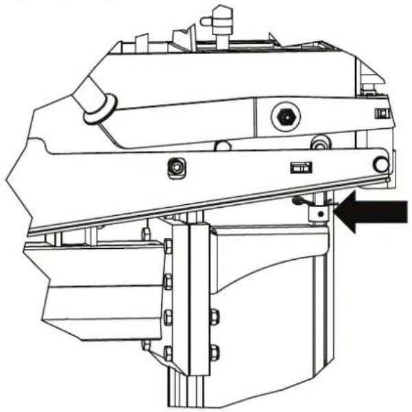
natural_image
Technical line drawing of a mechanical assembly with no visible text or symbolsFig. 4
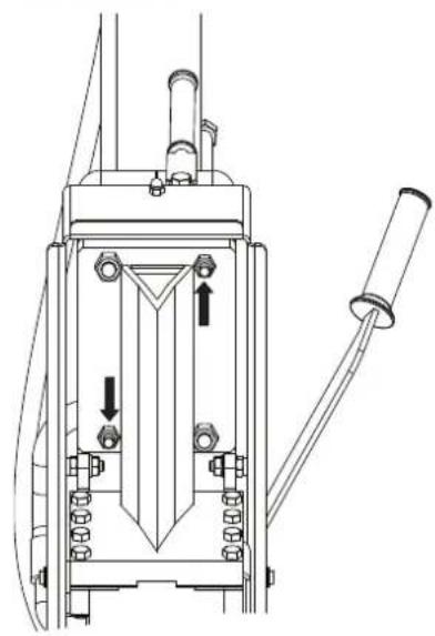
natural_image
Technical line drawing of a mechanical device with no visible text or symbolsFig. 5
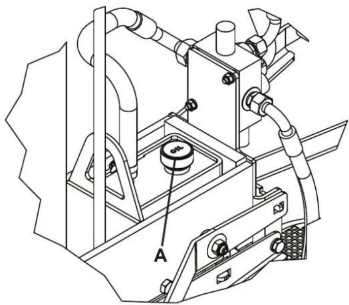
natural_image
Technical line drawing of a mechanical assembly with labeled component A (no text or symbols beyond label)Fig. 6
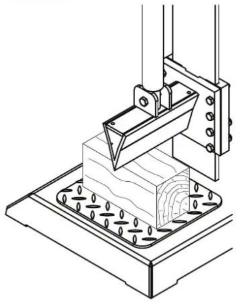
natural_image
Technical line drawing of a 3D printer or stamping machine with a wooden block and base plate (no text or symbols)Fig. 7
natural_image
Technical line drawing of a mechanical device with a bucket and pump, no text or symbols presentFig. 7.1
natural_image
Technical line drawing of a mechanical assembly with rollers, gears, and a tool (no text or symbols)Fig. 8
text_image
0 1 2 3 4 0 1 2 3Fig. 9
text_image
C A E B DFig. 10
natural_image
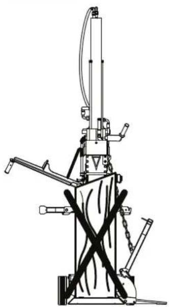
Technical line drawing of a mechanical device with intersecting rods and a vertical shaft (no text or symbols)
text_image
L1 16A 3N~ 50Hz/ 400/230V L2 L3 N PE ① ② OE IE 1 3 5 13 A1 2 4 6 14 A2 J<400V~ sw br ws rt gnge U V W Komponenten iste: 1: Gehäuse K900 2: KB-04 Jc:400V~ 3: Thermokonlakl 4: MotorKomponenten iste:
1: Gehäuse K900
2: KB-04 Jc:400V\~
3: Thermokontlakl
4: Motor
Technische Daten
| Institutes Datab. | X | Motor Zappy | E + 2w | Schipper hydansk | E-Motor zbywelle | e + 2w | Stiepperer hydansk E | Motor Zbywelle | e + 2w | Motor Zbywelle | e + 2w | Stiepperer hydansk E | Motor Zbywelle | e + 2w | Motor Zbywelle | e + 2w | Motor Zbywelle | e + 2w | Motor Zbywelle | e + 2w | Motor Zbywelle | e + 2w | Motor Zbywelle | e + 2w | Motor Zbywelle | e + 2w | Motor Zbywelle | e + 2w | Motor Zbywelle | e + 2w | Motor Zhydansk | ||
| X | 16070941 | 16070942 | 16070943 | 16070950 | 16070944 | 16070945 | 16070946 | 16070947 | 16070948 | 16070949 | 16070947 | 16070948 | 16070949 | 16070950 | 16070951 | 16070947 | 16070948 | 16070949 | 16070951 | 16070947 | 16070948 | 16070949 | 16070951 | 16070947 | 16070948 | 16070949 | 16070951 | 16070958 | 16070959 | 16070960 | 16070961 | ||
| Arl. Nr. | X | Motor Zappy | E + 2w | Schipper hydansk | E-Motor zbywelle | e + 2w | Stiepperer hydansk E | Motor Zbywelle | e + 2w | Motor Zbywelle | e + 2w | Motor Zhydansk E | Motor Zbywelle | e + 2w | Motor Zhydansk E | Motor Zbywelle | e + 2w | Motor Zhydansk E | Motor Zbywelle | e + 2w | Motor Zhydansk E | Motor Zbywelle | e + 2w | Motor Zhydansk E | Motor Zbywelle | e + 2w | Motor Zhydansk E | Motor ZbyWelle | e + 2w | Motor Zhydansk E | Motor ZbyWelle | e + 2w | Motor Zhydansk E |
| Indienstabe Datab. | X | Ox 7 1020 e | Ox 7 1020 e+2w | Ox 7 1020 e+2w | Ox 7 1020 e+2w | Ox 7 1020 e+2w | Ox 7 1020 e+2w | Ox 7 1020 e+2w | Ox 7 1020 e+2w | Ox 7 1020 e+2w | I-1320 e-ox 7 | I-1320 e-ox 7 | I-1320 e-ox 7 | I-1320 e-ox 7 | I-1320 e-ox 7 | I-1320 e-ox 7 | I-1320 e-ox 7 | I-1320 e-ox 7 | I-1320 e-ox 7 | I-2520 e+2w | I-2520 e+2w | I-2520 e+2w | I-2520 e+2w | I-2520 e+2w | I-2520 e+2w | I-2520 e+2w | I-2520 e+2w | I-2520 e+2w | I-2520 e+2w | ||||
| Sundizubderk: | |||||||||||||||||||||||||||||||||
| Deplung kkt. 1 / 2(106/0702) | X | Ja | Jia | Ja | Ja | Ja | Ja | Ja | Ja | Ja | Ja | Ja | Ja | Ja | Ja | Ja | Ja | Ja | Ja | Ja | Ja | Ja | Ja | Ja | Ja | Ja | Ja | Ja | Ja | Ja | Ja | ||
| Fartyromiting für (006/0101) | X | Ja | Ja | Ja | Ja | Ja | Ja | Ja | Ja | Ja | Ja | Ja | Ja | Ja | Ja | Ja | Ja | Ja | Ja | Ja | Ja | Ja | Ja | Ja | Ja | Ja | Ja | Ja | Ja | Ja | Ja | ||
| Geinkiewe w 100(006/0101) | X | Ja | Ja | Ja | Ja | Ja | Ja | Ja | Ja | Ja | Ja | Ja | Ja | Ja | Ja | Ja | Ja | Ja | Ja | Ja | Ja | Ja | Ja | Ja | Ja | Ja | Ja | Ja | Ja | Ja | Ja | ||
| Fartyromiting für Pum M Stütznd (2 Pum M Stütznd) | X | Ja | Ja | Ja | Ja | Ja | Ja | Ja | Ja | Ja | Ja | Ja | Ja | Ja | Ja | Ja | Ja | Ja | Ja | Ja | Ja | Ja | Ja | Ja | Ja | Ja | Ja | Ja | Ja | Ja | Ja | ||
| Fartyromiting für Pum M Stütznd (2 Pum M Stütznd) | X | Ja | Ja | Ja | Ja | Jia | Ja | Ja | Ja | Ja | Ja | Ja | Ja | Ja | Ja | Ja | Ja | Ja | Ja | Ja | Ja | Ja | Ja | Ja | Ja | Ja | Ja | Ja | Ja | Ja | Ja | ||
| Fartyromiting für Pum M Stütznd (2 Pum M Stütznd) | X | Ja | Ja | Ja | Ja | Ja | Ja | Ja | Ja | Ja | Ja | Ja | |||||||||||||||||||||
Geräuschkennwerte
Günzburger Straße 69
89335 Ichenhausen
| -Point cat. 1/2(16070702) | X | Yes | Standard equipment | Standard equipment | Standard equipment | Standard equipment | Standard equipment | Standard equipment | Standard equipment | Standard equipment | Standard equipment | Standard equipment | Standard equipment | Standard equipment | Standard equipment | Standard equipment | Standard equipment | Standard equipment | Standard equipment | Standard equipment | Standard equipment | Standard equipment | Standard equipment | Standard equipment | Standard equipment | Standard equipment | Standard equipment | Standard equipment | Standard equipment | Standard equipment | Standard equipment | Standard equipment | Standard equipment | Standard equipment | Standard equipment | Standard equipment |
| Driving device(16070704) | X | Standard equipment | X | X | Yes | X | X | X | X | X | X | X | X | X | X | X | X | X | X | X | X | X | X | X | X | X | X | X | X | X | X | X | X | X | X | X |
| Driving device(16070705) | X | Yes | Yes | Yes | Yes | Yes | Yes | Yes | Yes | Yes | Yes | Yes | Yes | Yes | Yes | Yes | Yes | Yes | Yes | Yes | Yes | Yes | Yes | Yes | Yes | Yes | Yes | Yes | Yes | Yes | Yes | Yes | Yes | Yes | Yes | |
| Joint start w 100(05018101) | X | X | Yes | Yes | X | X | Yes | Yes | X | X | Yes | X | X | Yes | Yes | X | X | Yes | Yes | X | X | Yes | Yes | X | X | Yes | Yes | X | X | Yes | Yes | Yes | X | X | Yes | |
| Forest which (16070707) | X | X | Yes | Yes | Yes | Yes | Yes | Yes | Yes | Yes | Yes | Yes | Yes | Yes | Yes | Yes | Yes | Yes | Yes | Yes | Yes | Yes | Yes | Yes | Yes | Yes | Yes | Yes | Yes | Yes | Yes | Yes | Yes | Yes |
Special accessories
| Standard accessories | X | Wood fixation device / run-up stop / Wood log filter | ||||||||||||||||||||
| X | Wood fixation device / run-up stop / Wood log filter | |||||||||||||||||||||
| X | Wood fixation device / run-up stop / Wood log filter | |||||||||||||||||||||
| X | Wood fixation device / run-up stop / Wood log filter | |||||||||||||||||||||
| X | Wood fixation device / run up stop / Wood log filter | |||||||||||||||||||||
| X | Wood fixation device / run up stop / Wood log filter | |||||||||||||||||||||
| X | Wood fixation device / run up stop / Wood log filter | |||||||||||||||||||||
| X | Wood fixation device / run up stop / Wood log filter | |||||||||||||||||||||
| X | Wood fixation device / run up stop / Wood log filter | |||||||||||||||||||||
| X | Wood fixation device / run up stop / Wood log filter | |||||||||||||||||||||
| PTO shaft | X | 300 | 300 | X | X | 300 | 300 | X | X | 300 | 300 | X | X | 300 | 300 | X | X | 300 | 300 | X | 350 | 350 |
| Revolution speed of min. | X | 30 | 30 | 25 | 30 | 30 | 30 | 25 | 30 | 30 | 30 | 25 | 30 | 30 | 25 | X | X | 25 | X | X | 25 | 25 |
| Tractor capacity | X | 30 | 30 | 25 | 30 | 30 | 30 | 25 | 30 | 30 | 30 | 25 | 30 | 30 | 25 | X | X | 25 | X | X | 25 | 25 |
| Weight | X | 286 | 284 | 311 | 258 | 308 | 295 | 325 | 267 | 373 | 328 | 342 | 285 | 373 | 362 | 387 | 347 | 375 | 364 | 389 | 349 | |
| Tractor hydraulic volume flow | L | X | X | X | min. 20 | X | X | X | min. 22 | X | X | X | min. 25 | X | X | X | min. 40 | X | X | X | min. 40 | |
| Oil flow rate | L | 15 | 15 | 15 | X | 17 | 17 | 17 | X | 20 | 20 | 20 | X | 28 | 28 | X | X | 28 | 28 | X | X | |
| Splitting knife, dimension L/W/H | mm | 240x75x120 | 240x75x120 | 240x75x120 | 240x75x120 | 240x75x120 | 240x75x120 | 240x75x120 | 240x75x120 | 240x75x120 | 240x75x120 | |||||||||||
| Working height two-hand mm | cm | 1130 | 1130 | 1130 | 1130 | 1130 | 1130 | 1130 | 1130 | 1130 | 1130 | 1130 | 1130 | 1130 | 1130 | 1130 | 1130 | 1130 | 1130 | 1130 | 1130 | |
| Working height max | cm | 1500 | 1500 | 1500 | 1500 | 1500 | 1500 | 1500 | 1500 | 1500 | 1500 | 1500 | 1500 | 1500 | 1500 | 1500 | 1500 | 1500 | 1500 | 1500 | 1500 | |
| Oil flow rate | L | 15 | 15 | 15 | X | 17 | 17 | 17 | X | 20 | 20 | 20 | X | 28 | 28 | X | X | 28 | 28 | X | X | |
| Tractor hydraulic volume flow | L | X | X | X | min. 20 | X | X | X | min. 22 | X | X | X | min. 25 | X | X | X | min. 40 | X | X | X | min. 40 | |
| Oil flow rate | L | 15 | 15 | 15 | X | 17 | 17 | 17 | 17 | X | 20 | 20 | X | 28 | 28 | X | X | 28 | 28 | X | X | |
| Technical data: X 0x 7 10-20 e | 0x 7 1020 pTO | 0x 7 1020 g+PTO OX | 7 1020 h OX 7 1320 e | 0x 7 1320 pTO | 0x 7 1320 g+pTO OX | 7 1320 h OX 7 1620 e | 0x 7 1620 pTO | 0x 7 1620 e+pTO OX | 7 1620 h | 0x 7 2020 e | 0x 7 2020 zw | 7 2020 h OX 7 | 2520 e OX 7 2520 zw | 0x 7 2520 e + zw OX | 7 2520 zw | 0x 7 2520 h | ||
| Act. No. | X | 16070941 | 16070942 | 16070943 | 16070950 | 16070950 | 16070944 | 16070945 | 16070945 | 16070945 | 16070945 | 16070954 | 16070955 | 16070956 | 16070957 | 16070958 | 16070959 | 16070960 |
| Propulsion | X | Electric motor | PTO | 0x 7 1020 | Electric motor + PTO | Factor hydraulic | Factor hydraulic | Tractor | Electric motor + PTO | Tractor | Electric motor + hydraulics | Electric motor PTO | Electric motor + PTO | Tractor motor | Electric motor | Electric motor + hydraulics | PTO | Electric motor + hydraulics |
| Output performance P2 | KW | 5.2 | X | 5.2 | X | 5.2 | X | 5.2 | X | 5.2 | X | 5.2 | X | 5.2 | X | 5.2 | X | 5.2 |
| Unit performance P1 | KW | 4.0 | X | 4.0 | X | 4.0 | X | 4.0 | X | 4.0 | X | 4.0 | X | 4.0 | X | 4.0 | X | 4.0 |
| Motor speed | T/min | 1380 | X | 1380 | X | 1380 | X | 1380 | X | 1380 | X | 1380 | X | 1380 | X | 1380 | X | 1380 |
| Operating mode | X | 56 40 % | X | 56 40 % | X | 56 40 % | X | 56 40 % | X | 56 40 % | X | 56 40 % | X | 56 40 % | X | 56 40 % | X | 56 40 % |
| Motor protection | X | yes | X | yes | X | yes | X | yes | X | yes | X | yes | X | yes | X | yes | X | yes |
| Zero voltage switch | X | yes | X | yes | X | yes | X | yes | X | yes | X | yes | X | yes | X | yes | X | yes |
| Phase inverter | X | yes | X | yes | X | yes | X | yes | X | yes | X | yes | X | yes | X | yes | X | yes |
Specific noise values
The according to the EN 23746 for the sound pressure level resp. EN 31202 (correction factor k3 after supplement A.2 from EN 31204 calculated) for the sound pressure level on the working site ascertained noise emission value amounts under the foundations of ISO 7904 supplement A performed working conditions to:

Sound pression level in dB Idle LWA / Processing LWA dB(A) 66 / 83
Sound pressure level on working site in dB Idle LpAeq / Processing LpAeq dB(A) 60 / 77
The specified values are emission values and therefore should not at the same time be reliable working site values. Although there is a corre-
lation between emission and immersion levels, it cannot unfailingly be derived if extra precautions need to be taken or not. Factors, which influence the actual availabe immersion value on working site, include the peculiarities of working area, other sources of noise, e.g. the number of machines and other adjoining processes. The allowed working values could vary from country to country. However, the information should qualify the user, to be able to make an estimation of the dangers and risk
General notes
We hope you have a lot of fun and success using your new machine.
Note:
Under current product liability regulations, the manufacturer of this equipment will not be liable for damages to the equipment or caused by it in the case of:
- improper handling,
- failure to observe the operating instructions,
• repairs by third parties, non-authorised technicians, - installation of and replacement by non-original spare parts,
- non-intended use,
- failures of the electrical system while not adhering to the electrical regulations and regulations of the VDE (German Association for Electrical, Electronic and Information Technologies) 0100, DIN 57113 / VDE0113.
Our recommendations:
Read the entire text of the operating instructions before installation and operation.
These operating instructions are to help you to get to know your machine and its intended fields of application.
The operating instructions contain important notes on how to work safely, properly, and efficiently with the machine and how to avoid hazards, save costs of repairs, keep downtimes short und improve reliability and product life of the machine.
In addition to the safety instructions in this manual, you must observe all regulations of your country applicable for the operation of the machine.
Keep the operating instructions close to the machine, protected by a plastic envelope against dirt and humidity. Any operator must read the operating instructions prior to work and follow them precisely. Only people trained to operate
the machine and who are aware of the associated dangers are permitted to work with the machine. The required minimum age must be observed.
• After unpacking, inspect all parts for possible transport damages. In the case of complaints you must inform the deliverer immediately. Subsequent complaints will not be accepted.
- Check the shipment to ensure that it is complete.
- Familiarise yourself with the equipment with the help of the operating instructions before putting the equipment into operation.
- Use only original parts as accessories and spare parts. You can buy spare parts from your specialist dealer.
- When you order, please state our order numbers as well as the equipment's type and year of manufacture.
General safety notes ⚠️
In this operating manual, points concerning your safety will be marked with this symbol:
△
WARNING: If you use electric tools, you should observe the general safety measures mentioned below in order to reduce the risk of fire, electric shock, and injury to people. Please read all instructions before working with these tools.
- Observe all safety instructions and warnings for the machine.
- Keep all safety instructions and warning labels on the machine complete and in legible condition.
- You must not remove the safety devices on the machine or make them inoperative.
- Check the power cords. Do not use faulty power cords.
-
Check that the two-hand control is functioning correctly before operation.
-
The operator must be at least 18 years of age. Trainees must be at least 16 years old, but may only work with the machine under supervision.
- Wear work gloves during work.
- Attention during work: injury hazard to fingers and hands.
- When splitting heavy or bulky materials, use appropriate appliance for support.
- Switch motor off for retooling, adjustment, and cleaning, as well as for maintenance and troubleshooting. Pull power plug!
• Installation, repairs and maintenance work on the electrical installation may only be carried out by qualified personnel. - All guards and safety mechanisms must be reinstalled immediately after completing the repairs or the maintenance work.
- The adjustments on the hydraulic valve and on the control levers must not be changed. Risk of accident and of destruction of the hydraulic components!
- Switch the motor off when leaving the working area. Pull power plug!
Additional Safety Instructions for Log Splitters
- The log splitter may only be operated by a single person.
- Wear protective gear (goggles/ visor, gloves, safety boots) to protect yourself from possible injuries.
- Never split logs with nails, wire or other objects in them.
- Logs already split and shavings pose a threat within the working area. There is the risk of tripping, slipping, or falling. Always keep the working area tidy.
- Never put your hands on moving parts while the machine is switched on.
- Only split logs with a maximal length of 1,130 mm.
- Only split logs with a minimal diameter of 60 mm and a maximum diameter of 600 mm
Intended use ⚠️
This machine complies with the current EC machinery directive.
- The hydraulic log splitter is designed for "stationary operation", logs may only be split standing upright and along the grain. The dimensions of the logs to be split:
•
logs cut to length 113 cm
- Never split logs lying horizontally or across the grain.
- The manufacture's safety, working, and maintenance instructions as well the di
mensions stated in the technical specifications must be observed.
- The applicable rules for accident prevention and other generally accepted rules concer
ning safety must be obeyed. -
The machine may only be operated, serviced, or repaired by persons familiar with it and aware of the risks. Arbitrary modifications of the machine exclude any liability of the manufacture for damages arising from this.
-
The machine may only be used with original accessories and original tools from the manufacturer.
- Every other use will be considered to be unintended use. The manufacturer assumes no liability for damages arising from this and it will be solely at the operator's own risk.
Accident prevention standards ⚠️
The machine may only be operated by qualified personnel who are well aware of the contents of this manual.
Before operating the machinery, you must check the integrity of the safety mechanisms and ensure that they are working properly.
Also before operation, you should familiarise yourself with the machine controls, following the operating instructions.
The specified capacity of the machine must not be exceeded. Under no circumstances the
machine must be used for anything else but its indented use.
All personnel must wear work clothes as stated in the regulations of the country in which the machine is operated. Wide, loose clothing, belts, rings, and necklaces should not be worn. Long hair should be tied back.
Try to keep the working area tidy at all times.
Tools, accessories, and spanners should be kept within reach.
During cleaning or maintenance work the machine must not be connected to the mains supply.
It is strictly prohibited to operate the machine without safety mechanisms or with safety mechanisms disengaged.
It is strictly prohibited to remove or modify safety mechanisms.
You should not carry out any maintenance or adjustments before having carefully read this manual.
The given maintenance schedule must be observed for safety reasons as well as to ensure that the machine performs properly.
The warning labels must be always clean and legible and must be observed in order to avoid accidents. If labels are damaged or missing or belong to parts that were replaced, then those labels must be replaced by original labels ordered from the manufacturer and be attached at the positions prescribed.
In case of fire, dry powder fire extinguishing agents must be used. A burning machine must not be extinguished with water because of the risk of a short circuit.
If the fire cannot be extinguished immediately, watch for liquids leaking.
During a longer fire the oil tank or the pressurised lines can explode: Therefore make sure that you are not getting into contact with the leaking liquids.
Dismantling and Disposal
The machine does not contain any materials that are hazardous to health or the environment, because it is manufactured from materials that
are either completely recyclable or can be disposed in a normal way.
For disposal, you should use specialist companies or qualified personnel, who know the possible risks and have read these operating instructions and follow them precisely.
If the machine falls into disuse, follow these steps under observance of all applicable accident prevention measures:
- Disconnect the energy supply (electrical or PTO),
- Remove all electrical wires and hand over to a specialised collecting point, while observing national regulations.
- Drain the oil tank and deliver the oil in a closed container to a collecting point, while observing national regulations.
- Deliver all other machine parts to a scrap collection point, while observing national regulations.
Make sure every part of the machine is disposed of in accordance with all applicable national regulations.
Residual risks ⚠
The machine was designed according to the state of the art and accepted safety standards. However, residual risks might occur during work.
- Risk of finger or hand injury by the cutting knife due to improper guidance or placement of the log.
- Injuries by the work piece being catapulted out of machine due to improper clamping or guidance.
- Electrical hazard due to use of improper power cords.
• Furthermore there might be non-obvious remaining risks despite all precautions.
- Residual risks can be reduced if safety instructions, intended use, as well as all operating instructions are observed.
Equipment Fig.1
- Control lever
- Wood retaining lever
- Control valve
- Backstop
- Retaining arm
- Splitting knife
- E-motor with switch
- Carrying wheel (without the three-point system)
- Three-point hitch
- Log lifter
Transport / Storage conditions
Transport with a fork lift truck:
For shipment, the machine is fixed to a pallet by steel bandings. It is protected by a plastic sheet cover.
At least two persons are required to lift it off the pallet.
Tilt it carefully to the side with the wheels and let it glide off the pallet.
Attention: The log splitter has a high centre of gravity - danger of tipping over!
Manual Transport
Transport by hand is permitted only with the driving device (see Accessories).
To transport the wood splitter
flip the froe until the machine rests on the wheel of the driving device and can thus be moved.
Caution, do not transport in the lying position!
Transport with a crane, fig. 2
Use the 2 holes A in the upper section of the machine for the transport on a crane-hook. Never lift the machine at the splitting knife!
Transport with Tractor
Power take-off must be turned off during transport.
The warning panel with rear light DIN 110030 must be mounted on the wood splitter and the rear light connected to the tractor.
Please ensure the following conditions:
• dry, sheltered storage location
• maximum humidity 80%
• temperature range from -20°C to +60°C
The machine should be operated under the following conditions:
| mini-mum | maxi-mum | recommended | |
| temperature 5 | C^ 40 C^ | 16 C^ | |
| humidity X | 95 % 70 % |
At ambient temperatures lower than 5^ C, the machine needs to run at idle speed for about five minutes for the hydraulic system to reach operating temperature.
Setting-up
Prepare the location, where the machine will stand. Clear enough space to ensure safe and trouble-free working.
The machine is designed for operation on level surfaces and must stand stably on a level, solid
Montage
Your log splitter is completely assembled
Function test
Before every use you should conduct a function test.
| Action Result | |
| Pressing both handles down. | The splitting knife moves down - as far as approx. 5 cm above the table. |
| Releasing either handle. | The splitting knife stays in its position. |
| Releasing both handles. | The splitting knife moves back into top position. |
Operating instructions
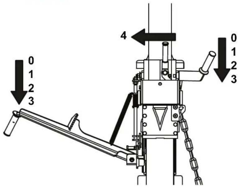
Lever positions on the control valve (Fig.8)
Position „0“
Splitting knife moves upwards and automatically to position "1"
Position "1"
Basic position, no movement at the splitting knife.
When the cylinder is extended and the return-stop is being activated the knife remains at position "1". The cylinder does not retract.
Position "2"
Splitting speed. The splitting knife moves at slow speed and with highest splitting force.
Position "3"
Fast speed. The splitting knife moves at highest speed and with reduced splitting force.
Setting during the raising of the cylinder
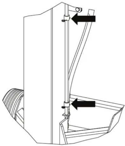
Adjust the nut to the lowest hole on the bar for 1 m wood (Fig. 3).
Always leave the upper nut with spring cotter in this position!
- Activate the return-stop. Position "4"
- If you are using a splitter with electric motor it is sufficient to press a shift knob.
- To turn on the device, press the green power switch.
- When using a PTO driven splitter please note the following:
- The connection to the cardan shaft must be performed after the coupling of the PTO lifting unit.
- The locking of the PTO lifting unit must be secured with appropriate safeguards.
- Now connect the drive shaft with the gear shaft and the PTO connector.
- Activate the return-stop. Position "4"
-
Switch on the PTO shaft.
-
Now operate both control levers carefully in order to move the cylinder SLOWLY upwards. It is most important that you pay attention to the hydraulic hoses!
- When the cylinder plate is at the boom, release one control lever and keep the other one still pressed.
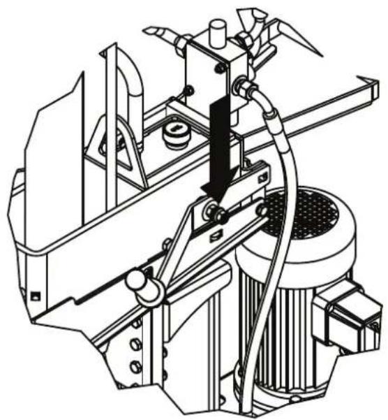
- Switch off the machine. Now you can secure the screws with the nuts in order to lock the cylinder (Fig. 4).
- The nuts and the washers are located on the control levers (Fig. 4.1)
- Never move upwards quickly, do not apply force!
- Errors in handling and operation are hereby explicitly excluded from the warranty.
- Now release the operating knobs, the splitting wedge is pulled upwards by the plunger. The wood splitter is now ready for use.
Only use cardan shafts with CE signs, declaration of conformity and operating instructions! Read these operating instructions carefully prior to operation!
Perform the above procedures only when the motor and the PTO connector are turned off and the ignition key is removed!
Adjustment during the lowering of the cylinder
- Adjust the nut to the lower hole on the bar. Lower the splitting knife onto a piece of wood of about 15cm height, switch off the machine. Fig. 6
- Unfasten the screw nuts on the cylinder, press an operation knob, and turn on the machine.
- Release the operation knob slowly. Lower the cylinder slowly, and switch off the machine.
Splitting
- At temperatures below 5^ leave the machine at idle speed for about five minutes so that the hydraulic system reaches operating temperature.
- Place the wood under the splitting knife in an upright position and press against the fixing bolt.
- Warning. The fixing bolt and the splitting knife are very sharp. Risk of injury!
- When you press down both operating levers simultaneously, the splitting knife moves down and splits the wood.
- Only split timber that has been cut straight.
- Split the wood vertically.
- Never split wood horizontally or diagonally!
- Wear appropriate gloves while splitting wood.
Length of wood
The hydraulic splitter is suitable for the splitting of short wood and wood by the metre. It is practical to adjust the upper stroke limitation to 3 to 5 cm.
Lifting limitation
- If you have logs of wood with a length of more than 100 cm place the nut in the upper hole of the bar (Fig. 3) and clamp with the locking pin.
- If you have logs of wood with a length of less than 65 cm place the nut in the middle hole and clamp with the locking pin.
Start-up
Make sure that the machine is completely and properly assembled. Before every use, check:
- the power cords for faults (cracks, cuts and such),
• the machine for possible damages,
• if all bolts are fastened tightly,
the hydraulic system for leaks, and the oil level.
Power on/off
Press the green button to power on.
Press the red button to power off.
Note: Check the function of the on/off-unit befo-
re every use by switching it on and off once.
Restart cut-out in case of power failures (zero voltage switch)
In case of a power failure, unintentionally pulling the power plug or a defect fuse the machine will automatically switch off. To restart the machine, press the green button on the switchbox again.
Operation with Tractor's Hydraulics
- Before putting the machine into service, make sure that the power cables are not
damaged.
- The tractor must have a flow connection and a load-free return connection.
- Ensure proper connection of the hoses.
- Hydraulic hoses shall be stored in the intended repository.
Operation with PTO
- Before connecting the machine to the three-point hitch of the tractor, make sure that the weight of machine is within the tractor's specifications. The weight of the machine can be found on the manufacturer type plate
- Make sure that the machine is connected correctly to the three-point hitch and that the safety bolts are always in place. The
[EMPTY]
upper link only in higher hole. The lower hole is for the driving devise.
- When working, be careful in order to prevent accidents or damages.
- Only connect the drive shaft only to the engine of the tractor when it is not running.
- Use only drive shafts that are approved and suitable for the use with the log splitter. Furthermore the drive shaft must be equipped with all safety mechanisms, which must be in good condition.
- Keep away from the drive shaft when it is in use.
- Make sure that the shaft speed of the tractor does not exceed the value specified on the type plate (max 300 rpm).
- It is recommended to wear earplugs or equivalent hearing protection.
- Do not operate the machine indoors. The
exhaust fumes are harmful to health. They can cause unconsciousness and therefore pose a threat to the operator. If it is necessary to work indoors or in covered surroundings, make sure that there is sufficient ventilation. Do not inhale the exhaust fumes!
Modifications of any kind to the machine are prohibited!
- For specific instructions regarding the drive shaft, refer to its user manual (delivered with the drive shaft).
- For maintenance work or if the splitting wedge is stuck, disconnect the machine from the tractor first, after stopping the tractor.
Never leave the machine unattended while it is still connected to the power source!
Using the log lifter
General information on the log lifter:
• The log lifter is ready for operation
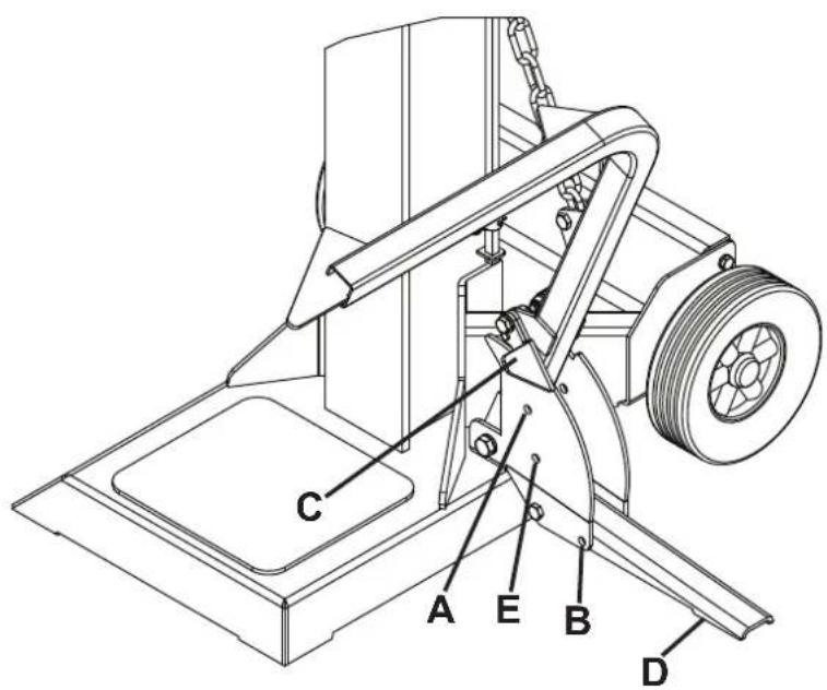
- If not used, the log lifter must be in the upper position. (Insert the hitch pins in the top hole; Fig.9 „A“) It can then be used as a second protection handle preventing lateral displacement of the log.
- For safety reasons, only the last link of the log lifter's chain will be attached to the suspension plate.
- Make sure that nobody is present in the working area of the log lifter
Using the Log Lifter:
- Pull the hitch pin from the lever fastener so that the lever tube can move freely
- The stand must be in the lowest position and must be secured with the hitch pin (hole „B“, Fig.9).
-
Guide the froe downwards until the lever tube of the log lifter completely rests on the ground. (Actuate the froe's backstop so that the froe remains in this position, see Working Instructions)
-
In this position, you can roll the log to be split on the lever's tube (The log must be placed between the two fastening points)
- Now unlock the froe's backstop (See: Working Instructions) and guide the splitting wedge upwards. (Caution! Do not stand in the working area of the log lifter! Risk of injury!)
- Now align the log and split it (See: Working Instructions)
• Take the log lifter back, or use it as a second protective arm
Notes on retracting the log lifter:
- Slightly guide the froe back (approx. 30 cm) and then actuate the backstop (See: Working Instructions)
- Now slightly lift the lever's tube of the log lifter with your hand (Fig.9, „A“), then lift the grid on the lever's tube so that the grid can rest on the edge of the lever's fastener. (Always guide the lever's tube manually)
- Now unlock the backstop (See: Working Instructions), then guide the froe completely downwards again. (Until the log lifter lies on the ground)
Transport Position of the Log Lifter:
- Guide the log lifter upwards with your hand until it clicks into place.
- Flap the stand (Fig.9, „D“) to the top, until it reaches a vertical position.
- Now insert the hitch pin in the hole (Fig.9, „E“) aligned with the hole of the stand, then secure the stand using the cotter pin (guide the chain with the cotter pin behind the lever's fastener)
Follow these instructions to ensure a fast and reliable work.
Electrical connection ⚠️
Inspect the power cords regularly for damage. Make sure that during this inspection the power cord is not connected to the mains supply.
The power cords must comply with the applicable VDE (German Association for Electrical, Electronic, and Information Technologies) and DIN (German Institute for Standardization) regulations. Use only power cords with the designation H 07 RN.
A type label on the power cord is prescribed.
Faulty power cords
Power cords often suffer insulation damages.
Causes are:
- Pinching, when power cords are routed through windows or door cracks.
- Bending due to improper attachment or routing of the power cords.
- Cuts due to driving over the power cords.
• Insulation damages caused by yanking it out of the power outlet. - Cracks in the insulation because of ageing. Such faulty power cords must not be used and are, due to the damaged insulation, a danger to life!
Three-phase motor 400 V/ 50 Hz Power supply 400 volts / 50 Hz.
Power cord and extension cord must have 5 conductors
= 3 P + N + PR. - (3/N/PE).
The extension wires must have a cross-section of at least 2.5 mm^2 and must not be longer than 20 m.
The power supply must be protected by a 16 A (or less) circuit breaker.
After connecting the power supply or after relocating, check the direction of rotation. Invert polarity if necessary.
Turn the polarity inverter inside the power plug.
Maintenance
Retooling, adjustment and cleaning activities are only to be carried out when the motor is switched off.
Unplug the mains plug.
Experienced craftsmen may perform minor repairs themselves.
Repair and maintenance activities on the
electric equipment may only be carried out by an electronics specialist.
All protection and safety appliances must be
fitted immediately after completion of repair and maintenance work.
We recommend:
- Clean the machine thoroughly after each
use!
- Splitting knife The splitting knife is a consumable which might need regrinding/re-sharpening or which has to be replaced with a new one.
- Two-hand operating facility The control and operating facility must remain smooth-running. Lubricate occasionally with a few drops of oil.
- Movable parts
- Keep the splitting knife guides clean. (dirt, splinters, bark, etc.)
- Lubricate slide bars with spray oil or grease
- Check oil level of hydraulics
Check hydraulic connections and screws for tightness and abrasive wear. If necessary retighten the screw connections.
When do I change the oil?
First oil change after 50 operating hours, then always after 250 operating hours.
Check the oil level.
Check the oil level frequently before each start-up. If the oil level is too low, the oil pump may be damaged.
Note: The oil level must be checked while the splitting knife is retracted. The oil dipstick is located on the splitting column in the filler plug A (Fig. 5) and is provided with 1 slot. If the oil level is at the lower end of the dipstick, this indicates that the minimum oil level has been reached. If this is the case, the oil must be refilled immediately. The slot indicates the maximum oil level.
The oil tank is situated in the splitting column and is filled with high-quality hydraulic oil by the manufacturer.
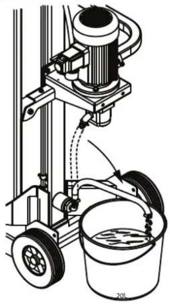
Change of the hydraulic oil and the oil filter. Place a container under the suction hose. Remove the hose clamp of the pump and pull off the suction hose. Caution: allow the oil to flow into the container! Fig. 7
Remove the suction hose completely and by slightly tilting, allow the remaining oil to drain into the container.
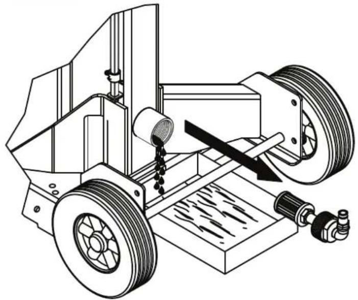
To change or clean the filter, remove the entire intake manifold by means of a flat spanner SW41 or pipe wrench! Fig. 7.1
Clean the filter and re-mount with new sealing tape, item no.: 1607 0333. Connect the suction hose again and secure with hose clamps.
Remove the filler plug and fill with new hydraulic oil.
Attention! Make sure that no dirt particles enter the oil tank.
Dispose of used oil accordingly by taking it to the local waste oil collection points. It is prohibited to drain used oil into the soil or to mix it with waste.
We recommend the following hydraulic oils: Q8 Haydn 46
Aral Vitam gf 22
BP Energol HLP-HM 22
Mobil DTE 11
Shell Tellus 22
or equivalent.
Do not use other oil grades! The use of other oil types affects the function of the hydraulic cylinder.
Only when operated by PTO: change the oil of the transmission gearing after the first 35 operating hours, then after 1,000 operating hours or at least once per year. Ensure that the connections of the hydraulic system do not leak.
Hydraulic system
The hydraulic system is a closed system with oil tank, oil pump and control valve.
The factory-made and completed system must not be modified or re-engineered.
Check the oil level frequently.
Too low an oil level may damage the oil pump. Check the hydraulic connections and screws for tightness frequently – retighten if necessary.
Prior to maintenance and checking procedures, clean the work space and have appropriate tools in good condition to hand.
The above-indicated time intervals refer to normal terms of use; if the machine is exposed to heavy load, those time intervals decrease accordingly.
Clean the machine casing, the panels and the control levers with a soft, dry cloth that you can moisten a little with a neutral cleaning agent. Do not use alcohol or benzene since they might damage the surfaces.
Keep oil and lubrication grease out of the reach of unauthorised personnel. Read the instructions on the containers carefully and observe them strictly. Avoid skin contact and rinse well after use.
Troubleshooting
In cases of errors not mentioned below, please contact the customer service of the company scheppach.
GB
| Error Possible causes Solution Degree of danger | |||
| The hydraulic pump does not run | No voltage Check whether the conductors have power supply | Danger of an electric shockThis work process must be performed by a maintenance electrician. | |
| The thermo-switch of the motor has turned itself off. | The thermo switch turns on again when the motor has cooled down.The motor can be re-started. | - | |
| The column does not move downwards | Low oil level Check the oil level and refill | Danger of contamination! | This work process can be carried out by the machine operator. |
| 2-manual shift not correct | Check the fixing of the levers | Risk of being cut! | |
| Dirt in the column guide Clean the column | |||
| Motor starts but the column does not move downwards | Incorrect rotating direction of the motor during three-phase current | Check rotating direction of the motor and shift to correct direction | Incorrect rotating direction can damage the pump |
Maintenance and repairs
All maintenance procedures must be performed by qualified personnel under strict observation of the available operating manual.
Prior to each maintenance, all possible precautions must be taken; turn off the motor and disconnect the power supply (if necessary, unplug the power plug). Place a sign on the machine which explains the outage of the device "Machine out of service due to maintenance:
unauthorized persons are not allowed to start up the machine or to remain in close proxim.
EU Confirmity declaration
We, scheppach Fabrikation von Holzbearbeitungsmaschinen GmbH, hereby declare that the machine described below, because of its design and construction, meets the relevant and basic safety and health requirements of the EC Machinery
Directive 2006/42/EC
Furthermore, the machine meets the Low Voltage Directive 2006/95/EEC,
The EMC Directive 2004/108/EEC
Outdoor-Directive 2000/14/EC
Designation: Hydraulik-Brennholzspalter
Type: Ox 7-1020e; Ox 7-1020zw; Ox 7-1020e/zw; Ox 7-1020h
Ox 7-1320e; Ox 7-1320zw; Ox 7-1320e/zw; Ox 7-1320h
Ox 7-1620e; Ox 7-1620zw; Ox 7-1620e/zw; Ox 7-1620h
Ox 7-2020e; Ox 7-2020zw; Ox 7-2020e/zw; Ox 7-2020h
Ox 7-2520e; Ox 7-2520zw; Ox 7-2520e/zw; Ox 7-2520h
Serial no.: From 1001
To implement the safety and health requirements specified in the EC directives, the following standards were used: EN-60204-1, EN 609-1
Internal measures have been taken to ensure that serial devices always meet the requirements of applicable EC directives and relevant standards
The following body
has carried out the EC-type examination specified in Annex IX of the 2006/42/CEE Directive
The product is identical to the type-approved model for which an B-GS-2008/031 EC type-examination certificate has been issued
Below the name and adress of the person responsible for compiling the technical documentation
Reinhold Bauer
Günzburger Straße 69
89335 Ichenhausen
Construction Manager
Nos recommendations:
Conditions de stockage:
| mini-mum | maximum recommendation |
Outdoor-Directive 2000/14/EC
Günzburger Straße 69
89335 Ichenhausen
Günzburger Straße 69
89335 Ichenhausen
| Grundausstaltung | |||||||||||||||||||||||||||||||||||||||||||||||||||||||||||||||||||||||||||||||||||||||||||||||||||||||||||||||||||||||||||||||||||||||||||||||||||||||||||||||||||||||||||||||||||||||||
| X | and | (16070702) | X | Gundausst. | X | X | ja | X | X | ja | X | X | X | ja | X | X | X | X | X | X | X | X | X | X | X | X | X | X | X | X | X | X | X | X | X | X | X | X | X | X | X | X | X | X | X | X | X | X | X | X | X | X | X | X | X | X | X | X | X | X | X | X | X | X | x | and | (16070702) | X | and | (16070702) | (16070702) | X | and | (16070702) | (16070702) | (16070702) | (16070702) | (16070702) | (16070702) | (16070702) | (16070702) | (16070702) | (16070702) | ||||||||||||||||||||||||||||||||||||||||||||||||||||||||||||||||||||||||||||||||||||||||||||||||||||||
Sonderzubehor:
| Standard prisuienstri | X | ||||||||||||||||||
| Devo nukolet / return stop / log zvedzaku | |||||||||||||||||||
| X | X | X | X | X | 350 | 350 | X | X | X | X | 350 | X | X | X | 350 | 350 | |||
| Ostaky vydovotno thirdele | Umin. | X | 300 | 300 | X | X | 300 | 300 | X | X | 300 | X | 300 | 300 | X | X | 300 | 300 | |
| Kapacila Itakonu | Ps | X | 25 | 25 | 25 | X | 25 | 25 | X | 25 | 25 | 25 | 25 | 25 | X | X | 25 | 25 | 25 |
| Himontost | kg | 286 | 284 | 311 | 258 | 308 | 295 | 325 | 267 | 328 | 315 | 342 | 285 | 373 | 362 | 387 | 347 | 375 | 364 |
| Prutok olele hydralidsko systemi terkdonu | L | X | X | X | min. 20 | X | X | X | min. 22 | X | X | X | min. 25 | X | X | min. 40 | X | X | X |
| Prutok ojele hydralidsko systemi terkdonu | L | 16 | 16 | 16 | X | 18 | 18 | 18 | X | 21 | 21 | 21 | X | 26 | 28 | 28 | X | 28 | 28 |
| Zakada, pouzitne rozmny D x S | nm | 345x410 | 355x460 | 345x410 | 355x460 | 345x410 | 355x460 | 345x410 | 345x410 | |
| Pracovi vyska pro obdunost obshnu | nm | 1500 | ||||||||
| Maximini delka dleventho spalku | cm | 1130 | ||||||||
| Siprad klin, rozmny D/S/V | nm | 240x75x120 | ||||||||
| Výška sputnictvoHYDRAJUKKAKVALE | 1980 | |||||||||||||||
| Síla špitni | to | 10 | 10 | 10 | 13 | 13 | 13 | 13 | 16 | 16 | 16 | 16 | 20 | 20 | 20 | 25 |
| Zdavih hydrajukkéhovalce | cm | 985 (1000) | ||||||||||||||
| Dobžováčačky 1(tychý posuv) | cm/s | 19,5 | 32 | 19,5 / 32 | X | 19,5 | 24 | 19,5/24 | X | 13,8 | 20 | 13,8/20 | X | 11,2 | 20 | 11,2/20 |
| Dobžováčačky 2 | cm/s | 8,8 | 16 | 8,8/16 | X | 7 | 12 | 7/12 | X | 6,5 | 9,8 | 6,5/9,8 | X | 7,2 | 8 | 7,2/8 |
| Spouščet očeky | cm/s | 19,5 | 28 | 19,5/28 | X | 12,2 | 21 | 12,2/21 | X | 9,7 | 16,5 | 9,7/16,5 | X | 8,4 | 10,5 | 8,4/10,5 |
| Výška zsztady | mm | 55 | ||||||||||||||
| Technische uhalen | X | 10670941 | 18070942 | 18070943 | 18070950 | 18070944 | 18070945 | 18070946 | 18070947 | 18070948 | 18070949 | 18070952 | 18070953 | 18070954 | 18070955 | 18070956 | 18070957 | 18070958 | 18070959 | 18070960 |
| X | 18070941 | 18070942 | 18070943 | 18070950 | 18070944 | 18070945 | 18070946 | 18070947 | 18070948 | 18070949 | 18070952 | 180670953 | 18070954 | 18070955 | 18070956 | 18070957 | 18070958 | 18070959 | 18070960 | |
| Altenb | X | 1020 h OX 7 | 1320 e OX 7 | 1320 zW | 1320 zW | 1320 e +ZW OX 7 | 1320 h OX 7 | 1620 e OX 7 | 1620 zW | 1620 h OX 7 | 2020 e OX 7 | 2020 zW | 7 2020 e +ZW OX 7 | 2520 e OX 7 | 2520 zW | 7 2520 e +ZW OX 7 | 2520 e OX 7 | 2520 zW | 7 2520 e +ZW OX 7 | 2520 zW |
| Pfilon P1 | X | 1020 h OX 7 | 1320 zW | 1320 zW | 1320 zW | 1320 e +ZW OX 7 | 1320 h OX 7 | 1620 e OX 7 | 1620 zW | 1620 h OX 7 | 2020 e OX 7 | 2020 zW | 7 2020 e +ZW OX 7 | 2520e OX 7 | 2520 zW | 7 2520 e +ZW OX 7 | 2520 zW | 7 2520 e +ZW OX 7 | 2520 zW | 7 2520 e +ZW OX 7 |
| Wikon P2 | X | 10670941 | 18070942 | 18070943 | 18070944 | 18070945 | 18070946 | 18070947 | 18070948 | 18070949 | 18070950 | 18070951 | 18070947 | 18070948 | 18070949 | 18070950 | 18070951 | 18070952 | 18070953 | 18070954 |
| Olecky molor | X | 18070941 | 18070942 | 18070943 | 18070944 | 18070945 | 18070946 | 18070947 | 18070948 | 18070949 | 18070950 | 18070951 | 180670947 | 18070948 | 18070949 | 18070950 | 18070951 | 18070952 | 18070953 | 18070954 |
| Pfuvzni režim | X | 18070941 | 18070942 | 18070943 | 18070944 | 18070945 | 18070946 | 18070947 | 18070948 | 18070949 | 18070950 | 18070947 | 180670948 | 18070949 | 18070950 | 18070951 | 18070952 | 18070953 | 18070954 | 18070955 |
| Ochana molor | X | 18070941 | 18070942 | 18070943 | 18070944 | 18070945 | 18070946 | 18070947 | 18070948 | 18070949 | 18070950 | 180710951 | 180670952 | 180670953 | 180670954 | 180670955 | 180670956 | 180670957 | 180670958 | 180670959 |
| Ostrac multevno napeši | X | 18070941 | 18070942 | 18070943 | 18070944 | 18070945 | 18070946 | 18070947 | 18070948 | 18070949 | 18070950 | 180670951 | 180670952 | 180670953 | 180670954 | 180670955 | 180670956 | 180670957 | 180670958 | 180670959 |
| Fazovy minič | X | 18070941 | 18070942 | 18070943 | 18070944 | 18070945 | 18070946 | 18070947 | 18070948 | 18070949 | 18070950 | 180670x955 | 180670x956 | 180670x957 | 180670x958 | 180670x959 | 180670x960 | 180670x961 | 180670x962 | 180670x963 |
| Rozmery DiSry | mm |
Günzburger Straße 69
89335 Ichenhausen
text_image
Exploded view diagram of a mechanical device with detailed assembly labels and part numbersox 7 - 1020 / 1607 0941
ox 7 - 1320 / 1607 0944
ox 7 - 1620 / 1607 0947
ox 7 - 2020 / 1607 0953
ox 7 - 2520 / 1607 0957
ox 7 - 1020 / Sonderzubehör - 1607 0702
ox 7 - 1320 / 1607 0944
ox 7 - 1620 / 1607 0947
ox 7 - 2020 / 1607 0953
ox 7 - 2520 / 1607 0957
1607 0702
text_image
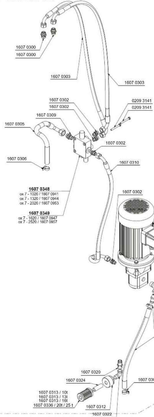
1607 0300 1607 0300 1607 0303 1607 0302 1607 0302 1607 0309 1607 0305 1607 0306 1607 0302 1607 0310 1607 0348 ox 7 - 1020 / 1607 0941 ox 7 - 1320 / 1607 0944 ox 7 - 2020 / 1607 0953 1607 0349 ox 7 - 1620 / 1607 0947 ox 7 - 2520 / 1607 0957 1607 0320 1607 0324 1607 0313 / 10t 1607 0313 / 13t 1607 0313 / 16t 1607 0336 / 20t / 25 t 1607 0312 1607 0322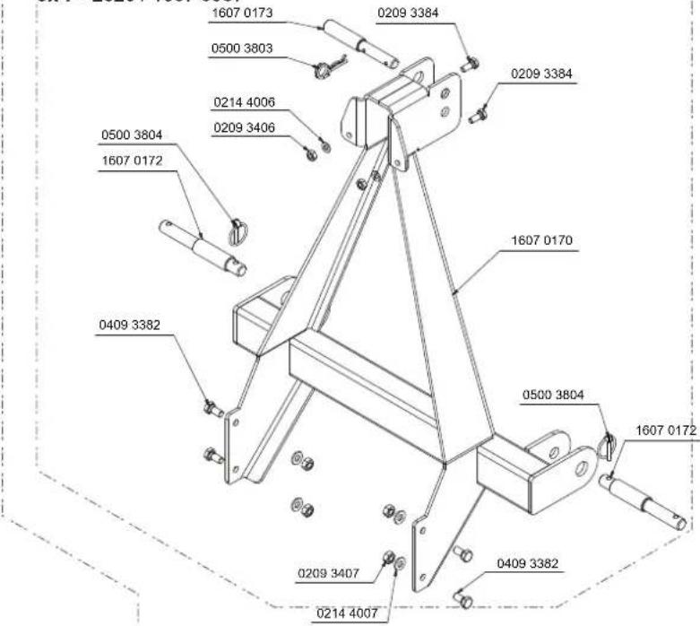
text_image
1607 0173 0209 3384 0500 3803 0214 4006 0209 3406 0500 3804 1607 0172 0409 3382 1607 0170 0500 3804 1607 0172 0209 3407 0214 4007 0409 3382ox 7 - 1020 / 1607 0941 ; 1607 0943
ox 7 - 1320 / 1607 0944 ; 1607 0946
ox 7 - 1620 / 1607 0947 ; 1607 0949
ox 7 - 2020 / 1607 0953 ; 1607 0955
ox 7 - 2520 / 1607 0957 ; 1607 0959
text_image
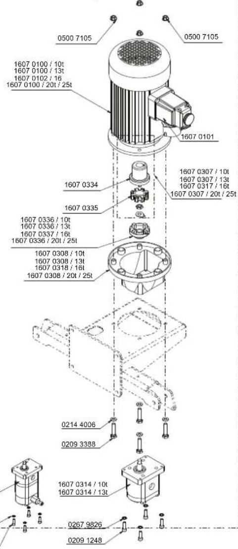
0500 7105 0500 7105 1607 0100 / 10t 1607 0100 / 13t 1607 0102 / 16 1607 0100 / 20t / 25t 1607 0101 1607 0334 1607 0335 1607 0336 / 10t 1607 0336 / 13t 1607 0337 / 16t 1607 0336 / 20t / 25t 1607 0308 / 10t 1607 0308 / 13t 1607 0318 / 16t 1607 0308 / 20t / 25t 0214 4006 0209 3388 1607 0314 / 10t 1607 0314 / 13t 0267 9826 0209 1248
text_image
ox 7 - 1000 / 1607 0901 1607 0704 0214 4006 0209 3382 0214 4006 0209 3382 1607 0150 0503 1121 1607 0156
text_image
ox 7 - 1020 / 1607 0943 ox 7 - 1320 / 1607 0946 ox 7 - 2520 / 1607 0959 ox 7 - 2520 / 1607 0943 ox 7 - 1020 / 1607 0942 ox 7 - 1320 / 1607 0945 ox 7 - 2520 / 1607 0948 ox 7 - 1620 / 1607 0948 ox 7 - 2020 / 1607 0954 ox 7 - 2520 / 1607 0958 ox 7 - 2520 / 1607 0959 1607 0316 1607 0340 1607 0388 1607 0439 1607 0480 1607 0530 1607 0598 1607 0639 1607 0686 1607 0738 1607 0798 1607 0848 1607 0898 1607 0948 1607 1018 1607 1078 1607 1128 1607 1172 1607 1238 1607 1284 1607 1338 1607 1384 1607 1438 1607 1488 1607 1548 1607 1598 1607 1648 1607 1698 1607 1748 1607 1798 1607 1848 1607 1898 1607 1948 1607 2008 1607 2058 1607 2108 1607 2158 1607 2208 1607 2258 1607 2308 1607 2358 1607 2408 1607 2458 1607 2508 1607 2558 1607 2608 1607 2658 1607 2708 1607 2758 1607 2808 1607 2858 1607 2908 1607 2958 1607 3008 1607 3058 1607 3108 1607 3158 1607 3208 1607 3258 1607 3308 1607 3358 1607 3408 1607 3458 1607 3508 1607 3558 1607 3608 1607 3658 1607 3708 1607 3758 1607 3808 1607 3858 1607 3908 1607 3958 1607 4008 1607 4058 1607 4108 1607 4158 1607 4208 1607 4258 1607 4308 1607 4358 1607 4408 1607 4458 1607 4508 1607 4558 1607 4608 1607 4658 1607 4708 1607 4758 1607 4808 1607 4858 1607 4908 1607 4958 1607 5008 1607 5058 1607 5108 1607 5158 1607 5208 1607 5258 1607 5308 1607 5358 1607 5408 1607 5458 16OCTO OZOZ x-252O / (x-252O) / (x-252O) / (x-252O) / (x-252O) / (x-252O) / (x-252O) / (x-252O) / (x-252O) / (x-252O) / (x-252O) / (x-252O) / (x-252O) = (x-252O) / (x-252O) / (x-252O) / (x-252O) / (x-252O) / (x-252O) = (x-252O) / (x-252O) / (x-252O) = (x-252O) / (x-252O) = (x-252O) / (x-252O) = (x-252O) = (x-252O) = (x-252O) = (x-252O) = (x-252O) = (x-252O) = (x-252O) = (x-252O) = (x-252O) = (x-252O) = (x-252O) =
text_image
05013108 02098507 16070466 02093158 02144007 02098507 16070415 04093387
text_image
02091279 16070412 04093382 16070435 16070468 16070410 02091279 02144009 02144007 02093407 02093399DE

Nur für EU-Länder.
Only for EU countries.
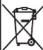
Do not dispose of electric tools together with household waste material! In observance of European directive 2012/19/EU on wasted electrical and electronic equipment and its implementation in accordance with national law, electric tools that have reached the end of their life must be collected separately and returned to an environmentally compatible recycling facility.
FR
Apparent defects must be notified within 8 days from the receipt of the goods. Otherwise, the buyer's rights of claim due to such defects are invalidated. We guarantee for our machines in case of proper treatment for the time of the statutory warranty period from delivery in such a way that we replace any machine part free of charge which provably becomes unusable due to faulty material or defects of fabrica-
tion within such period of time. With respect to parts not manufactured by us we only warrant insofar as we are entitled to warranty claims against the upstream suppliers. The costs for the installation of the new parts shall be borne by the buyer. The cancellation of sale or the reduction of purchase price as well as any other claims for damages shall be excluded.