BASA 7.0 - Saw SCHEPPACH - Free user manual and instructions
Find the device manual for free BASA 7.0 SCHEPPACH in PDF.


| Product Type | Band Saw |
| Brand | Scheppach |
| Model | BASA 7.0 |
| Dimensions (L x W x H) | 2060 x 1050 x 1150 mm |
| Table Dimensions | 840 x 640 mm |
| Work Height | 900 mm |
| Weight | 250 kg |
| Power Supply | 230 V / 50 Hz (2.80 kW) or 400 V / 50 Hz (3.80 kW) |
| Rated Input Power P1 | 2.80 kW (230 V) / 3.80 kW (400 V) |
| Output Power P2 | 2.00 kW (230 V) / 2.90 kW (400 V) |
| Cutting Speed (2 speeds) | 460 m/min (hardwood) and 775 m/min (softwood) |
| Cutting Height at 90° | 400 mm |
| Admissible Width | 590 mm |
| Parallel Cutting Width | 300 mm |
| Table Tilt Range | -15° to +47° |
| Band Wheel Diameter | 600 mm |
| Blade (standard) | 20 x 0.45 x 4425 mm |
| Longitudinal Stop Length | 650 mm |
| Sound Pressure Level (idle) | 85 dB(A) |
| Sound Pressure Level (machining) | 95 dB(A) |
| Machinable Materials | Wood, similar materials, non-ferrous metals, steel (with special blade) |
| Maintenance and Cleaning | Regularly clean blade and table, lubricate guides, check blade condition |
| Spare Parts and Repairability | Use only original Scheppach parts; electrical repairs by a professional |
| Safety | Protective covers, automatic stop when cover is opened, emergency stop via disconnection |
Frequently Asked Questions - BASA 7.0 SCHEPPACH
User questions about BASA 7.0 SCHEPPACH
0 question about this device. Answer the ones you know or ask your own.
Ask a new question about this device
Download the instructions for your Saw in PDF format for free! Find your manual BASA 7.0 - SCHEPPACH and take your electronic device back in hand. On this page are published all the documents necessary for the use of your device. BASA 7.0 by SCHEPPACH.
USER MANUAL BASA 7.0 SCHEPPACH
natural_image
Exterior view of a Schpeppach Basa 7.0 industrial machine (no signage or text on the device itself)| D | Bandsäge 7 | |
| GB | Band Saw 14 | |
| FR | Scie à Ruban 21 | |
| I | Tafelcirkelzaag 29 | |
| NL | Bandzaag 36 | |
| ES | Sierra de cinta 43 |
| P | Serra sem-fim 50 | |
| SE | Bandsåg 57 | |
| FIN | Vannesaha 64 | |
| NO | Bandsåg 71 | |
| DK | Båndsav | 78 |
1
natural_image
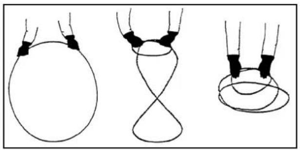
Three line drawings of hands holding black clips, illustrating a geometric or mechanical concept (no text or symbols)2
natural_image
Close-up of a mechanical component with black structural elements and white surfaces, no visible text or symbols.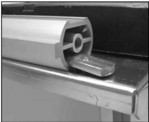
natural_image
Close-up of a metallic mechanical component with a circular opening and a handle, mounted on a metal bracket (no visible text or symbols)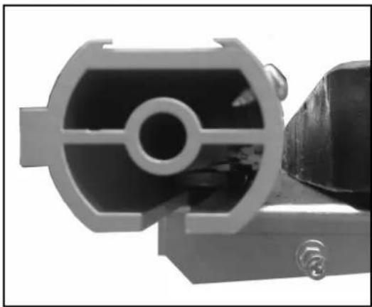
natural_image
Close-up of a mechanical component with internal cavities and a black housing (no visible text or symbols)3
natural_image
Technical line drawing of mechanical assembly components (no text or symbols)4
natural_image
Close-up of a mechanical assembly with metal components and a circular component (no visible text or symbols)5
natural_image
Technical drawing of a mechanical assembly with cross-sectional and top views (no text or symbols)4
text_image
Schnittgeschwindigkeit 460 m/min 1 <--> 3 1200 m/min 2 <--> 4 0501 2529 2 17

natural_image
Close-up of a mechanical device with a gear and central component (no visible text or symbols)8
natural_image
Close-up of a mechanical component with a cylindrical tool inserted, showing internal components and directional arrows (no text or symbols)9
natural_image
Close-up of a mechanical knob with a plus sign and curved arrow, no readable text or symbols present.10
natural_image
Close-up of a mechanical gear assembly with visible teeth and central hub (no text or symbols)11
natural_image
Close-up of a mechanical assembly with metallic components and a central shaft (no visible text or symbols)12
natural_image
Close-up of a black mechanical lever handle with directional arrows and plus/minus signs (no text or symbols on the lever itself)13
text_image
Technical diagram of a mechanical gear assembly with numbered components labeled '1'14
natural_image
Close-up of a mechanical assembly with metal components and a cutting tool (no visible text or symbols)15
natural_image
Person using a lathe machine to cut wood on a workbench (no visible text or symbols)16
natural_image
Person using a sawto machine to cut wooden panel, no visible text or symbols17
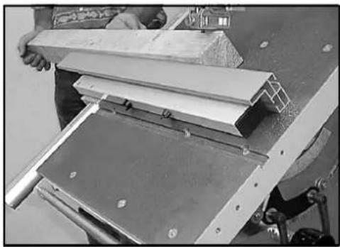
natural_image
Close-up of a hand operating a machine with metal components and a wooden plank (no visible text or symbols)18
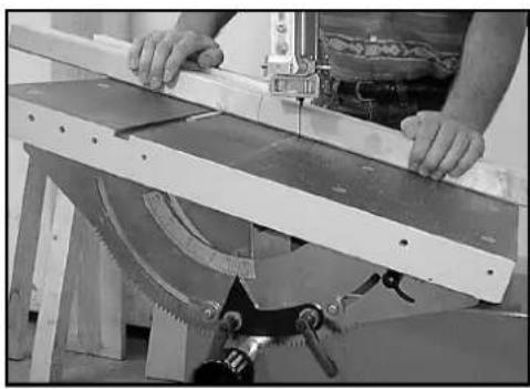
natural_image
Person operating a machine tool with a cutting board and saw (no visible text or symbols)19
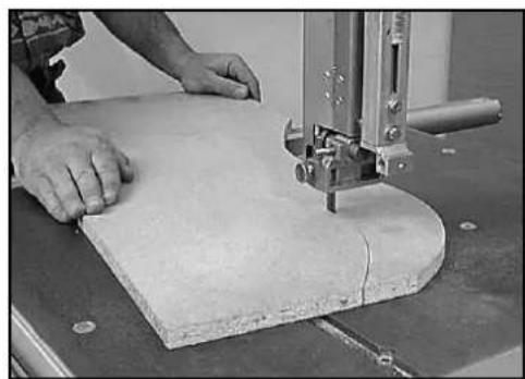
natural_image
Person using a 3D saw machine to cut a rectangular block on a workbench (no visible text or symbols)20
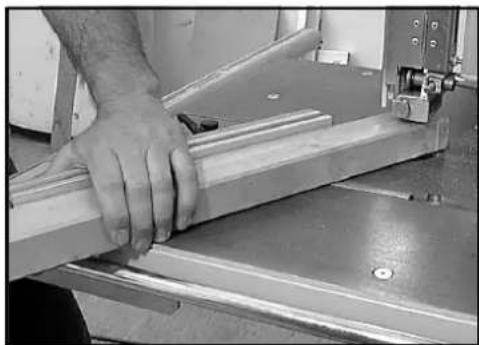
natural_image
Close-up of a hand operating a metal workbench with a mechanical clamp (no visible text or symbols)21
natural_image
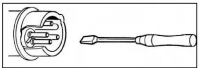
Technical line drawing of a screwdriver and its internal component (no text or symbols)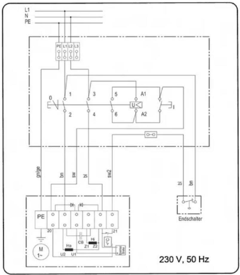
text_image
L1 N PE PE L1 L2 L3 0 1 2 3 4 5 6 A1 U A2 I gn/ge bn sw bi sw2 PE M 1~ 20 Ha CB Hi U2 U1 Z1 Z2 C Endschalter 230 V, 50 Hz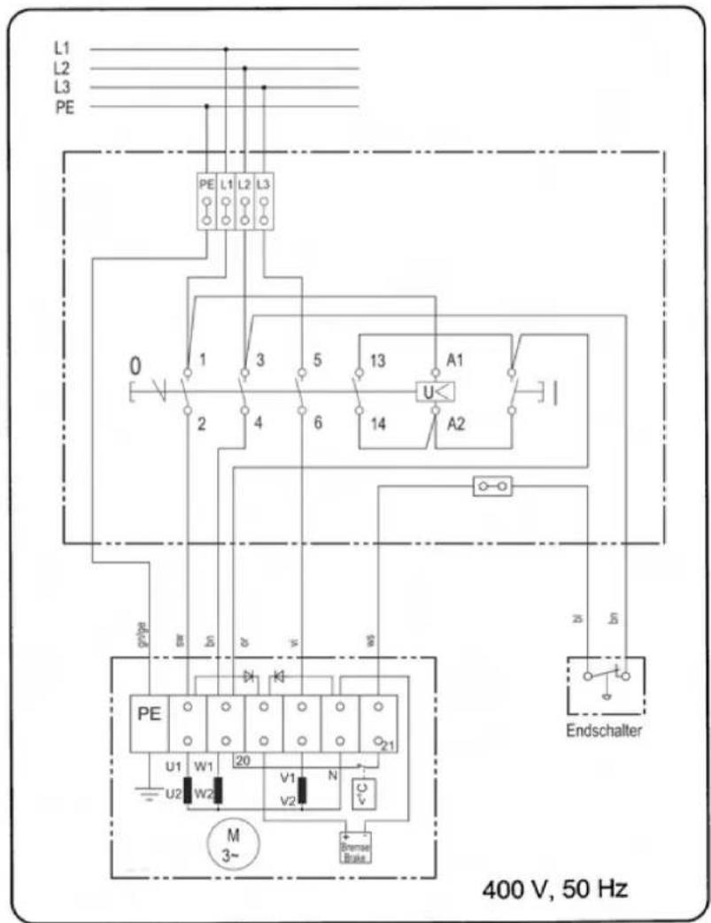
text_image
L1 L2 L3 PE PE L1 L2 L3 0 1 3 5 13 A1 2 4 6 14 A2 gs/pe gr sl sl ws PE U1 W1 20 V1 N U2 W2 V2 V M 3~ Bremse Blade Endschalter 400 V, 50 HzLieferumfang
Bandsäge Basa 7.0
Sägeband 20 mm
Längsanschlag
Schiebestock
Günzburger Straße 69
89335 Ichenhausen
Deutschland
Suction connectio piece, 100 mm diam
Push stick
Assembly Accesores
Operating instructions
Technical data
Length/width/height mm 2060x1050x1150
Bench size mm 840x640
Working height mm....900
Sawband mm 20x0,45x4425
Band wheel diameter mm....600
Cutting height at 90° mm....400
Clearance width mm 590
Parallel cutting width mm 300
Parallel stop length mm 650
Bench swing range mm.....degrees -15°/+47°
Cutting speed with 2 switching levels m/min 1200
Weight kg 250
| Motor 230 V / 50 Hz 400 V / 50 Hz | |
| Consumption P1 (kW) 2,80 3,80 | |
| Output P2 (kW) 2,00 2,90 |
Noise parameters
The noise emission values determined according to EN 23746 for the sound level and according to EN 31202 (coefficient of correction k3 calculated according to Appendix A.2 of EN 31204) for the sound level at the workplace are as follows, based on the working conditions listed in ISO 7904 Appendix A:
Sound level at the workplace in dB
Idle running LpAeq =85 dB(A)
Operation LpAeq = 95 dB(A)
A measurement uncertainty allowance K = 4 dB applies to the mentioned emission values.
Machine description
Due to its perfected design, the machine offers a versatile application for processing wood and plastics in the workshop.
The upper and lower bandwheel is protected by a fixed guard and an articulated cover. Upon opening the cover, the machine is switched off. Switching on again is only possible with the cover closed. The non-cutting part of the sawbelt above the table top is covered by a guard fixed
to the sawbelt guide, the latter being protected against inadvertent opening by the fixed guard of the upper band wheel. The non-cutting part of the sawbelt under the table top is protected by a fixed cover.
The swivelling range of the table from -15^ to +47^
allows versatile cutting possibilities (e.g)
- Longitudinal cuts
- Crosscuts
- Diagonal cuts
• Curved and irregular cuts
• Cuts for dovetails and tenons - On-edge cuts of squared beams
Please consult also the working hints in the operating instructions
General notes
- After unpacking, check all parts for any transport damage. Inform the supplier immediately of any faults.
- Later complaints cannot be considered.
- Make sure the delivery is complete.
- Before putting into operation, familiarize yourself with the machine by carefully reading these instructions.
- Use only original scheppach accessories, wearing or replacement parts. You can find replacement parts at your scheppach dealer.
- When ordering, include our item number and the type and year of construction of the machine.
NOTE:
In accordance with valid product liability laws, the manufacturer of this device shall not be responsible for damage to and from this device which results from:
- Improper care.
- Noncompliance with the Operating Instruc
tions.
- Repairs made by unauthorized persons.
- The installation and use of any parts which are not original scheppach replacement parts.
- Improper use and application.
- Failure the electrical system as a result of non compliance with the legal and applicable electrical directives and VDE regulations 0100, DIN 57113 / VDE 0113.
⚠️ We recommend that you read through the entire operating instructions before putting into operation.
These operating instructions are to assist you in getting to know your machine and utilize its proper applications.
The operating instructions contain important notes on how you work with the machine safely, expertly, and economically, and how you can avoid hazards, save repair costs, reduce downtime and increase the reliability and service life
of the machine.
In addition to the safety requirements contained in these operating instructions, you must be careful to observe your country's applicable regulations.
The operating instructions must always be near the machine. Put them in a plastic folder to protect them from dirt and humidity. They must be read by every operator before beginning work and observed conscientiously. Only persons who have been trained in the use of the machine and have been informed of the various dangers may work with the machine. The required minimum age must be observed.
In addition to the safety requirements contained in these operating instructions and your country's applicable regulations, you should observe the generally recognized technical rules concerning the operation of woodworking machines.
Safety notes
△ In these operating instructions we have marked the places that have to do with your safety with this sign.
- Please pass on safety notes and instructions to all those who work on this machine.
- Personnel entrusted with work on the machine must have read the operating instructions and in particular the chapter on safety before beginning work. Reading the instructions after work has begun, is too late. This applies especially to persons working only occasionally on the rmachine, e.g. during setting up or rnaintenance.
- Observe all safety instructions and warnings attached to the machine.
- See to it that all safety instructions and warnings attached to the machine are complete and perfectly legible.
- Check all power supply lines. Do not use defective lines.
- Make sure that the machine stands stable on firm ground.
- Insure sufficient lighting in the work area and the area around the machine.
- Caution when working: There is a danger to fingers and hands from the rotating tool.
- When working on the machine, all safety mechanisms and covers must be mounted.
-
Keep children away from the machine when it is connected to the power supply.
-
Operating personal must be at least 18 years of age. Trainees must be at least 16 years of age, but may only operate the machine under adult supervision.
- Persons working on the machine may be not diverted from their work.
- The working space on the machine must be free of chips and wood scrap.
- Wear only close-fitting clothes. Remove rings, bracelets and other jewelry.
• Always wear safety goggles when working. - Wear a cap or hair net to protect long hair.
- Wear suitable gloves to change the sawband.
- Do not wear work gloves when working on the saw.
- Observe the correct rotational speed setting on the machine.
- The safety mechanism on the machine may not be removed or rendered unusable.
- Cleaning, changing, calibrating, and setting of the machine may only be carried out when the motor is switched off. Pull the power supply plug and wait for the rotating tool to completely stop.
- Connection and repair work on the electrical installation may be carried out by a qualified electrician only.
-
All protection and safety devices must be replaced after completing repair and maintenance procedures.
-
Switch the machine off and pull power supply plug when rectifying any malfunctions.
- Use a suction unit to suck up wood shavings and sawdust. The current speed at the suction connection piece should be 20 m/s.
- Check the saw band guide and the saw band tension before starting up.
- Do not use nicked saw bands or those that have an altered form.
- Replace table inserts that have worn saw slots.
- When sawing round wood, make sure that the work piece does not turn.
- For sawing heavy or cumbersome pieces, use the appropriate working aids for bracing. (Special accessory roller stands).
- Place the upper saw band guide as closely as possible to the work piece.
- On slanted table plates, attach the longitudinal stop on the lower table plate half.
- Do not brake the saw band with side pressure after switching off.
- Remove work pieces that have become stuck only with the motor switched off and with the saw band at a standstill.
- Cut off the external power supply of the machine even if only minor changes of place are envisaged. Properly reconnect the machine to the supply mains before recommissioning.
- When leaving the work place, switch the motor off. Pull the power supply plug.
Use only as authorized
⚠️ CE tested machines meet all valid EC machine guidelines as well as all relevant guidelines for each machine.
- All protective and safety device must be mounted on the machine before beginning work.
- The machine is designed to be operated by one person. The operator is responsible for all other persons in the working area.
- Observe all safety instructions and warnings attached to the machine.
- See to it that safety instructions and warnings attached to the machine are always complete and perfectly legible.
- The bandsaw with the supplied tools and accessories is designed exclusively for sawing wood, material similar to wood, and non-ferrous metals and steel.
- The maximum dimensions for workpieces to be processed is may not exceed the bench size in the standard version. Clearance width: 440 mm, Clearance height: 300 mm
- For larger workpiece dimensions which require tipping of the table top, the table extension or the dolly (special accessories) must be used.
- The band saw can also be used for sawing metal when it is equipped with a special saw band dolly (special accessory) and a operated at an adapted cutting speed. Metal allows with more than 80 % magnesium may not be processed due to the danger of fires.
- When used in enclosed rooms, the machine must be connected to a vacuum exhaust unit. Use the dust extractor to remove matchwood or saw dust. The vacuum support flow rate must be 20 m/s. Subatmospheric pressure 860 Pa.
- The automatic switching unit is available as a special accessory.
Type ALV 2 Art. No. 7910 4010 230 V/50 Hz Type ALV 10 Art. No. 7910 4020 400 V/230 V/50 Hz
- The vacuum exhaust unit automatically switches on after a 2-3 second delay after the machine tool is turned on. This avoids overloa
ding the circuit fuse.
- After turning off the machine tool, the vacuum exhaust unit remains on for an additional 2-3 seconds and is then automatically switched off. Remaining dust is thereby removed by vacuum exhaust, as required by German regulations governing hazardous materials. This results in savings in electricity consumption and reduces noise levels, as the vacuum exhaust unit is on only during machine tool operation.
- A suction device which conforms with commercial regulations must be used for suction in commercial areas.
- Do not switch off or remove suction units or dust extractors while the work machine is in operation.
- The machine must only be used in technically perfect condition in accordance with its designated use and the instructions set out in the operating manual, and only by safety-conscious persons who are fully aware of the risks involved in operating the machine. Any functional disorders, especially those affecting the safety of the machine, should therefore be rectified immediately.
- The safety, work and maintenance instructions of the manufacturer as well as the technical data given in the calibrations and dimensions must be adhered to.
- Relevant accident prevention regulations and other, generally recognized safety-technical rules must also be adhered to.
- The machine may only be used, maintained, and operated by persons familiar with it and instructed in its operation and procedures. Arbitrary alterations to the machine release the manufacturer from all responsibility for any resulting damages.
- The machine may only be used with original acces sories and original tools made by the manufacturer.
- Any other use exceeds authorization. The manufacturer is not responsible for any damages
resulting from unauthorized use; risk is the sole responsibility of the operator.
Symbols

Read the manual

Use hearing protection and protective goggles
Only for EU countries
Do not dispose of electric tools with household waste material! In observance of european directive 2002/96/EC o wasted electrical and electronic equipment and its implementation in accordance with national law, electric tools that have reached the end of their life must be collected separately ad returned to an environmentally compatible recycling facility
Other Notes:
In these operating instructions we have marked the places that have to do with your safety with this sign: △
Remaining hazards
- The machine has been built using modem technology in accordance with recognized safety rules. Some remaining hazards, however, may still exist.
- The moving saw belt can cause injuries to fingers and hands when the work piece is not correctly fed.
- Thrown work pieces can lead to injury if the work piece is not properly secured orfed, such as working without a limit stop.
• Wood chips and sawdust can be health
hazards.
Be sure to wear personal protective gear such as safety goggles. Use a vacuum exhaust system.
- Defective saw blades can cause injuries. Regularly inspect the structural integrity of sawblades.
- Danger of injury to fingers and hands when changing the saw band. Wear suitable work gloves.
- The use of incorrect or damaged mains cables can lead to injuries caused byelectricity.
• Danger of injury when switching the machine
on due to start-up of saw band.
- Long hair and loose clothing can be hazardous when the belt saw is in motion. Wear personal protective gear such as a hair net and tight fitting work clothes.
- Even when all safety measures are taken, some remaining hazards which are not yet evident may still be present.
- Remaining hazards can be minimized by following the instructions in „Safety Precautions“, „Proper Use“ and in the entire operating manual.
Transport
The machine may only be transported with suitable
lifting devices (crane or fork lift). The connection point for the rope (crane) is on the upper band wheel cabinet.
Never lift trom the saw bench.
If the machine is to be moved frequently within the work area, use of the wheel assembly special accessory is recommended.
Montage
The machine is not completely assembled for reasons of transport.
Assembly tools:
13 mm fork wrench
5 mm hexagonal socket wrench
(not included in delivery)
Guide pipe
Fig."2"
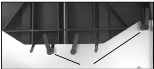
The fence plate underneath the sawblade has been fitted in the works.
Before attaching the guide tube, check the fence plate for tight fit.
If necessary, tighten the clamping levers (1).
Fit the steel holding devices for the guide tube at the lett and right-hand side of the fence plate.
2 cheese head screws M8 x 16
2 washers
2 steel holding devices
Push the guide lube mto the holding devices from the side. Before tightening the hexagon bolts, check the parallelity of the guide tube with the table (dimension „x“).
Dimension „x“ must be identical at the front and at the rear of the table.
Fence
Fig. „3“
- The fence can be used to the left or the right of the saw band depending on wone requirements.
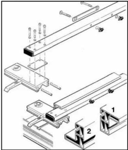
Screw together the feace pipe, intermediate plate, and guide slide (handscrewed). To da this, insert both threaded screws into the guide slots.
4 washer
4 cheese head screws
6
M6x20
- The divider plate to carry the fence is screwed onto the fence pipe on the right or the left depending on the work requirements.
Do not tighten the wing nuts!
2 saucer-head screws
2 washers
2 wing nuts
Place fence rail onto the divider plate.
M 6 x 75
6
M6
Position 1: for work with a higher contact surface
Position 2: for work with a lower contact surface
Place the cam lever on the guide slide horizontally. Place the guide slide onto the guide pipe and push the cam lever down - clamp.
On the guide pipe, the upper scale applies to position 1; the lower scale to position 2.
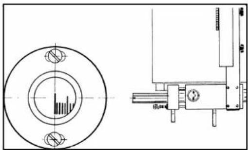
Fence adjustment
Fig."4"
Place the fence on the guide rail.
Place a straight strip on the sawband running upwards and downwards.
Place an angle on the strip and on the fence.
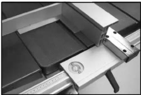
Adjusting the reading glass Fig."5"
The guide tube must project over the sawblade to such an extent that the scale on the guide tube is positioned directly under the zero mark of the magnifying glass.
Release the two belts of the magnifying glass and set the graduation mark precisely above the zero mark of the scale.
Retighten the bolts of the magnifying glass.
Setting before initial operation
The electrical current supply is interrupted by a limit switch when the housing lid is opened!
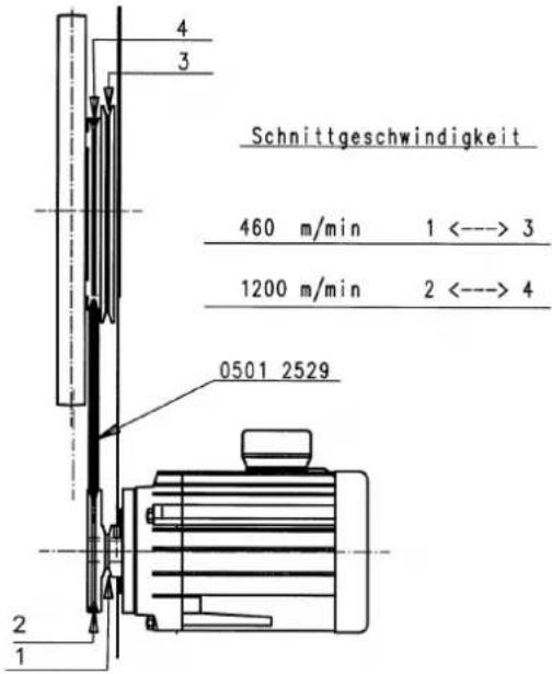
Cutting speeds Fig. „6“
Band saw are quipped with 2 cutting speed.
IMPORTANT!
The cutting speed may only be set while the machine is at a full stop. Pull the mains plug!
Two levels
460 m/min. for wood and hardwood
775 m/min. for soft wood
V-belt 10 x 1072 mm
Cutting speed - levels I - II
463 m/min. 1 to 3
775 m/min. 2 to 4
The machine is delivered with apre-set cutting speed of 775 m/min for wood and hardwood
Sawband
Selecting the correct sawband is decisive for cutting performance. Observethe table of the Operating Instructions.
Narrow sawbands can cut smaller radii than broad saw bands.
The smallest radius for blade widths
6/10/15/25mm
25/40/75/185 mm
Use only sharpened, flawless sawbands. Faulty sawbands increase the risk of accidents and reduce cutting performance.
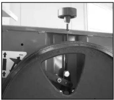
Changing sawbands
Fig."8"
The machine is delivered with a new, standard sawband (15 mm).
The sawband may only be changed when the mains plug is pulled!
Always wear suitable gloves when handling sawbands!
The sawband is loosened for removal by turning the upper handle counterclockwise. The new sawband is tensioned by turning the upper handle clockwise.
IMPORTANT when installing a sawband:
- Reset the counterpressure bearings and guide rollers.
- Check sawband for flaws (cracks, broken teeth) before installation.
- Check the running direction of the sawband before placing onto the band wheels. Teeth should point downwards towards the saw bench.
- The sawband must be placed between the upper and lower guide rollers.
- Tighten the placed sawband lightly.
- Tum the band wheel clockwise by hand and carry out the final tightening while the band is running evenly.
- Broad sawbands must be tensioned more firmly than narrow ones.
- Overtensioning of the sawband can lead to premature breakage.
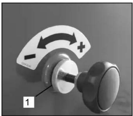
Sawband path side correction Fig."9"
Side correction may only be carried out with the machine at a tull stop and with the mains plug pulled!
The sawband must run on the center of the band wheels. Loosen the knurled nuts (1) on the underside of the of the handle.
Turn the upper band wheel by hand in the cutting direction while simultaneously turning the handle to the right (+).
The saw band then runs more toward the rear. When the sawband runs evenly, re-tighten the knurled nuts on the handle.
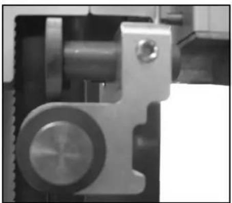
Counterpressure bearing Fig. „10“
Insure that the sawband runs evenly before setting the counterpressure bearing.
The setting must be carried out while the machine is at a full stop!
The counterpressure bearings take the feed pressure of the workpiece.
Set the counterpressure bearings above and below saw bench so that they contact the saw-band lightly. Tum the band wheel by hand in the sawing direction at the same time.
The counterpressure bearings must run with the sawband during operation.
Reset the counterpressure bearings every time the sawband is changed!
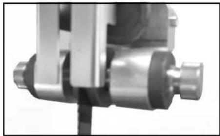
Guide rollers
Fig."11"
Insure that the sawband runs evenly before setting the guide rollers.
The setting must be carried out while the machine is at a full stop!
The guide rollers take the side pressure of the workpiece.
Reset the guide rollers above and below saw bench to the suitable sawband width. They may reach up to the base of the teeth of the saw-band.
Set the guide rollers so that they contact the sawband lightly. Tum the band wheel by hand in the sawing direction at the same time.
The guide rollers must run with the sawband during operation.
The sawband must not jam!
Reset guide rollers every time the sawband is changed!
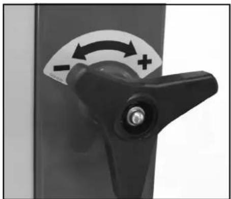
Cutting height adjustment Fig."12"
The setting must be carried out while the machine is at a full stop!
The cutting height is adjustable from 0 - 400 mm over the beneh.
Height adjustment is carried out continually using the large hand wheel and remains in any
position due to the automatic clamping function. For your own safety, always set the sawband guide as close to the workpiece as possible.
Sawbench Fig."13"
The saw bench is set at the factory.
The continuous saw bench swing range reaches trom + 47° to - 15°.
The greatest swing range allows 45^ mitered cuts.
The setting must be carried out while the machine is at a tull stop!
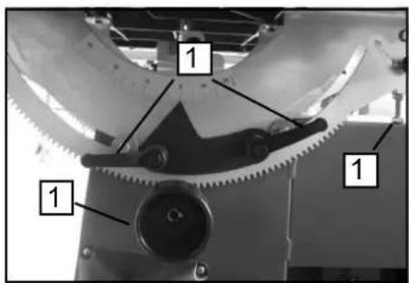
One can readjust the bench at a 90^ angle to the sawband using the setting screw (1) under the bench. (Use a square as an aid)!
Table adjustment to +47°
- Loosen both lock levers (2).
• Tum the handle (3) clockwise.
- Re-tighten the lock handles (2) in the desired position according to the scale.
Table adjustment to - 15°
- Loosen both lock levers (2).
- Tum the handle (3) one quarter revolution to the right and swing the adjustment screw (1) on the ball handle to the lett.
• Tum the handle (3) counterclockwise.
- Re-tighten the lock handles (2) in the desired position according to the scale.
Test the exact angle setting of the table with a sample piece before beginning work.
Parallel alignment of the sawband to the saw bench
Fig. „14“
Exact parallel alignment is especially important for work with the traverse cutting gauge special accessory.
Check parallel alignment with the fence rail and a low angle.
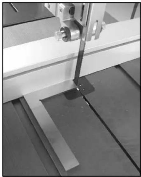
Place the fence rail on the saw band running upwards and downwards. Place the low angle on the fence rail as well as along the longitudinal groove.
If there are deviations, loosen the 8 hexagonal nuts of the table attachment swinging segment and readjust the saw bench appropriately.
Re-tighten the hexagonal nuts firmly!
Set-Up
Prepare the workplace where the machine is to be placed. Insure sufficient room to allow safe work without malfunctions. The machine is designed to operate in closed rooms and must be placed stably on firm level ground. Stability
is insured by attachment to the ground with 4 screws.
At least 2 persons are required to lower the machine from the pallet. Starting in the working position, tip the machine to the left and pull out the pallet to the right
Working Information
The following recommendations are examples of the safe use of band saws.
The following safe working methods should be seen as an aid to safety. They cannot be applied suitably completely or comprehensively to every use. They cannot treat every possible dangerous condition and must be interpreted carefully.
- Connect the machine to a suction unit when working in closed rooms. A suction device which conforms with commercial regulations must be used for suction in commercial areas.
- Loosen the sawband when the machine is not in operation (e.g. after finishing work). Attach a notice on the tension of the saw band to the machine for the next user.
- Collect unused sawbands and store them safely in a dry place. Check for faults (teeth, cracks) before use. Do not use faulty sawbands!
-
Wear suitable gloves when handling saw-bands.
-
All protective and safety devices must be securely mounted on the machine before beginning work.
- Never clean the sawband or the sawband guide with a hand-held brush or scraper while the sawband is running. Resin-covered sawbands impair working safety and must be cleaned regularly.
- For your own protection, wear protective glasses and hearing protection. Wear a hairnet if you have long hair. Roll up loose sleeves over the elbows.
- Always position the sawband guide as near the workpiece as possible when working.
- Insure sufficient lighting in the work area and around the machine.
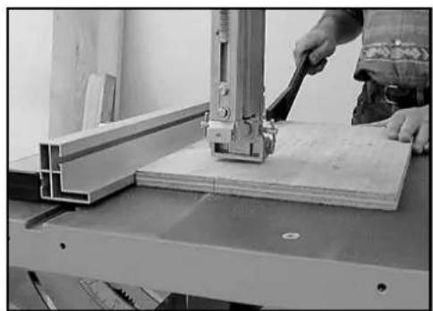
• Always use the fence for straight cuts to keep the workpiece from tipping or slipping away. - When working on narrow workpieces with manual feed, use the push stick.
- For diagonal cuts, place the saw bench in the appropriate position and guide the workpiece
on the fence.
- To cut dove-tails and dove-tailed tenons or wedges swing the saw bench to the plus or minus position. Insure safe workpiece guidance.
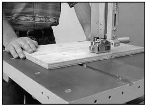
- For arced and irregular cuts, push the workpiece evenly using both hands with the fingers together. Hold the workpiece with your hands on a safe area.
- Use a pattern for repeated arced or irregular cuts.
- Insure that the workpiece does not roll when cutting round pieces.
- Use the traverse cutting gauge special accessory for safety when making traverse cuts.
- To safely cut round plates, use the circular cutting unit special accessory.
Electrical connection
The installed electric motor is connected and is ready to work.
The connection complies with the relevant VDE and DIN regulations.
The customer-side mains supply and the used extension line must meet these regulations. Installations, repair, and maintenance work relating to the electric installation may only be performed by specialists.
Important Notes
The electric motor has been designed for the S 1 operating mode.
In case of an overload of the motor, it turns off automatically. After a cooling period (duration varies), you can turn on the motor again.
Defective Electric Connection Lines
Often, insulation damages occur on electrical connection lines.
Causes are:
-
Drag marks if connection lines are led through window or door clearances.
-
Kinks due to improper attachment or routing of the connection line.
- Cuts caused by running over the connection line.
- Insulation damages caused by pulling the connection line out of the wall socket.
- Fissures caused by the ageing of the insulation.
Such defective electric connection lines must not be used and are hazardous due to the insulation damages.
Regularly check the electrical connection lines for damages. Please make sure that the connection lines are disconnected from the mains supply during the check.
Electrical connection lines must comply with the relevant VDE and DIN regulations. Only use connection lines labelled with H 07 RN. The labelling of the connection cable with the type specification is required.
AC motor
- The supply voltage must be 230 V / 50 Hz.
- Extension lines up to a length of 25 m must have a cross section of 1.5 square millime-
tres. Extension lines with a length of more than 25 m must have a minimum cross section of 2.5 square millimetres.
3. The mains connection is protected with a delay-action fuse of 16 A.
Rotary current motor
- The supply voltage must be 400 V / 50 Hz.
- Mains supply and extension line must be five-wire = 3 P + N + SL.
- Extension lines must have a minimum cross section of 1.5 square millimetres.
- The mains connection is protected with a maximum of 16 A.
- In case of mains supply or change of location, the direction of rotation must be checked. If required, the polarity must be reversed.
If you have further questions, please specify the following:
- Motor manufacturer
- Kind of current of the motor
- Data from the machine type plate
- Data from the switch type plate If you return the motor, always return the complete drive unit with the switch.
Maintenance
Carry out refitting, setting measurement and cleaning work only when the motor is switched off. Pull the plug and wait for the sawband to come to a full stop.
An experience worker can carry out minor-repairs on the machine himself.
Repair and maintenance work on the electrical
system may only be carried out by a qualified
electrician.
All protective and safety devices must be re-attached immediately after completed repair and maintenance work.
We recommend:
- The swinging segments of the bench, the saw-band tensioning unit and the guide of the cutting height adjustment unit must always move easily.
Treat these parts with a lubricant spray when necessary to maintain these functions.
- Clean the sawband regularly. Wood leaves resin remnants which stick to the sawband and impair working safety and performance.
- Keep the bench surface free of resin.
- Do not use cleaning agents or thinners which are easily flammable or which emit harmful vapors to clean the sawband and bench.
Use the concentrated resin remover special
accessory.
- Check sawbands regularly for faults. Replace faulty sawbands immediately.
- Check saw bench insert.
Replace wom saw bench insert.
- Rubber lining of the band wheels
The rubber lining of the band wheels becomes ripped and worn by the metal sawband over time.
Exact sawband alignment is then no longer possible. Working safety and performance are impaired.
Replace the band wheels!
Replacement wheels can be ordered from your scheppach dealer as with allother replace-
ment parts.
- Check the setting of the sawband guide regularly and readjust it if necessary.
Remove the sawband guide for readjustment.
Troubleshooting
| Failure Possible cause Solution | ||
| Motor does not start a) No current in the socket a) Check mains fuse | ||
| b) Switch or capacitor defective b) Have checked by electrician | ||
| c) Electrical extension line defective c) Pull mains plug, check, replace | ||
| d) Incorrect connection line 3-400 V d) 5-line connection, at 1.5 mm^2 diameter | ||
| e) Housing lid open (limit switch) e) Close housing lid exactly | ||
| Incorrect motor rotation direction | Incorrect connection | Reverse polarity of wall socket by electrician |
| Sawband slips or jumps down a) Upper band | wheel a) Carry out side correction according to Fig."9" | |
| b) Saw band guide | b) Set according to Fig. „10" and „11" | |
| c) Incorrect saw band | c) Select according to table | |
| d) Fence not parallel to sawband | d) Set fence according to Fig. „4" | |
| Burn marks on wood | a) Sawband dull | a) Replace sawband |
| b) Incorrect sawband b) Select according to table | ||
| c) Incorrect cutting speed | c) Set cutting speed according to figure „6" | |
| d) Fence not parallel to sawband | d) Set fence according to Fig. „4" | |
| Sawband jams | a) Sawband dull | a) Replace sawband |
| b) Sawband sticky with resin | b) Clean sawband | |
| c) Saw band guide | c) Set according to Fig. „10" and „11" | |
Günzburger Straße 69
89335 Ichenhausen
Deutschland
Authorized: Reinhold Bauer
complies wit the relevant provisions of the following EG-Directives 2014/35/EU
More Directives: EC EMC Directive 2014/30/EU
EC-type examination certificate
GS-Certificate
Applied harmonized European Standards:
Authorized subject to the technical:
Reinhold Bauer

Günzburger Straße 69
89335 Ichenhausen
Deutschland
Autorisé: Reinhold Bauer
Günzburger Straße 69
89335 Ichenhausen
Deutschland
meeton zeker heidsfactor K = 4 dB
NL
Machinebeschrijving
Günzburger Straße 69
89335 Ichenhausen
Deutschland
Günzburger Straße 69
89335 Ichenhausen
Deutschland
Günzburger Straße 69
89335 Ichenhausen
Deutschland
Günzburger Straße 69
89335 Ichenhausen
Deutschland
Representerad av: Reinhold Bauer
Günzburger Straße 69
89335 Ichenhausen
Deutschland
Asiamiehet:: Reinhold Bauer
Günzburger Straße 69
89335 Ichenhausen
Deutschland
Representert ved: Reinhold Bauer
Günzburger Straße 69
89335 Ichenhausen
Deutschland
Wear suitable work gloves when handling saw bands!
- Saw band should be handled carefully to protect them from damage.
- Collect untensioned sawbands which are not in use and secure them with a band. Fig.1
- Store sawbands in a dry place away from children in the original packages.
- Check for faults like faulty teeth
FR
text_image
Technical diagram of a mechanical assembly with labeled components and part numbers, including wheel, gears, and motors.Basa 7.0
scheppach
text_image
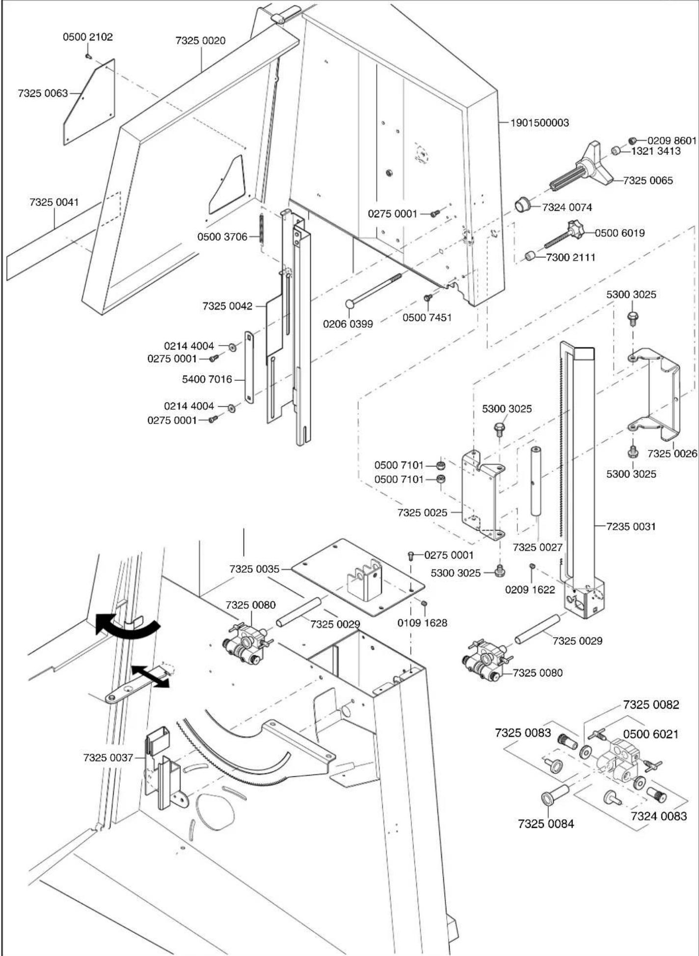
0500 2102 7325 0063 7325 0041 0500 3706 7325 0042 0214 4004 0275 0001 5400 7016 0214 4004 0275 0001 1901500003 0209 8601 1321 3413 7325 0065 7324 0074 0500 6019 7300 2111 0275 0001 0206 0399 0500 7451 5300 3025 5300 3025 7325 0026 5300 3025 7235 0031 5300 3025 7325 0025 7325 0027 7325 0029 7325 0080 7325 0083 7325 0084 7325 0083 7325 0084 7325 0083 7325 0082 7325 0081 7325 0084
text_image
Technical diagram of a mechanical assembly with labeled components and part numbers, likely from an electronics or industrial machine.Garantie D
Apparent defects must be notified within 8 days from the receipt of the goods. Otherwise, the buyer's rights of claim due to such defects are invalidated. We guarantee for our machines in case of proper treatment for the time of the statutory warranty period from delivery in such a way that we replace any machine part free of charge which provably becomes unusable due to faulty material or defects of fabrica-
tion within such period of time. With respect to parts not manufactured by us we only warrant insofar as we are entitled to warranty claims against the upstream suppliers. The costs for the installation of the new parts shall be borne by the buyer. The cancellation of sale or the reduction of purchase price as well as any other claims for damages shall be excluded.