ROWELD P110 - Welding ROTHENBERGER - Free user manual and instructions
Find the device manual for free ROWELD P110 ROTHENBERGER in PDF.

| Product type | Heated element butt welding machine for PE, PP and PVDF pipes |
| Brand | Rothenberger |
| Model | ROWELD P110 |
| Category | Welding |
| Welding range (diameter) | 20 - 110 mm |
| Maximum displacement | 165 mm |
| Electrical connection | 230 V a.c. / 115 V a.c., 50/60 Hz |
| Heating element power | 800 W |
| Heating plate | 180 x 130 mm |
| Weight (machine only) | 2.6 kg |
| Weight (complete machine) | 11.3 kg |
| Weight (with transport case) | 43.0 kg |
| Dimensions (transport case) | 540 x 345 x 355 mm (LxWxH) |
| Adjustable welding temperature | 160°C to 285°C (320°F to 545°F) |
| Main functions | Butt welding, milling, making bent segments |
| Supplied accessories | Base machine, milling device, electronic heating element, table mounting device, clamping elements ∅110 mm for pipe and fitting, reduction rings, transport case |
| Safety instructions | Read warnings, wear PPE, avoid explosive atmospheres, use an RCD outdoors |
| Maintenance and cleaning | Clean the guide rods, replace milling blades if worn, clean the heating element with ethanol (>99.8%) when cold |
| Repairability and spare parts | Repairs by a ROTHENBERGER approved workshop, parts available from customer service |
| Standards and directives | Complies with DVS 2207, DVS 2212 part 1 |
| General information | Use reserved for qualified specialists, do not use in explosive atmosphere |
Frequently Asked Questions - ROWELD P110 ROTHENBERGER
User questions about ROWELD P110 ROTHENBERGER
0 question about this device. Answer the ones you know or ask your own.
Ask a new question about this device
Download the instructions for your Welding in PDF format for free! Find your manual ROWELD P110 - ROTHENBERGER and take your electronic device back in hand. On this page are published all the documents necessary for the use of your device. ROWELD P110 by ROTHENBERGER.
USER MANUAL ROWELD P110 ROTHENBERGER
natural_image
Mechanical device with cylindrical and linear components mounted on a base (no visible text or symbols)EN Instructions for use
rothenberger.com
Intro
EU-DECLARATION OF CONFORMITY
We declare on our sole accountability that this product conforms to the standards and guidelines stated.
DECLARATION EU DE CONFORMITÉ
ROWELD P110 Heating element:
2014/30/EU, 2014/35/EU, 2011/65/EU,
EN 60204-1, EN 61000-3-2, EN 61000-3-3,
EN 55014-1, EN 55014-2, ISO 12100
Manufacturer/ authorized representative signature
ppa. Thorsten Bühl
i. V. Maximilian Gottschalk
Director Corporate Head of Innovation
Technology Management
Kelkheim, 20.01.2022
Technische Unterlagen bei/ Technical file at:
D-65779 Kelkheim/Germany
no. 55844 ROWELD P110, 40-110mm, 230V
no. 055844Z ROWELD P110, 40-110mm, 230V Swiss
no. 55924 ROWELD P110, 40-110mm, 115V
Intro
| DEUTSCH - Originalbetriebsanleitung!Bedienungsanleitung bitte lesen und aufbewahren! Nicht wegwerfen! Bei Schäden durch Bedienungsfehler erlischt die Garantie! Technische Änderungen vorbehalten! | Seite 2 |
| ENGLISHPlease read and retain these directions for use. Do not throw them away! The warranty does not cover damage caused by incorrect use of the equipment! Subject to technical modifications! | Page 9 |
| FRANÇAISLire attentivement le mode d'emploi et le ranger à un endroit sûr! Ne pas le jeter! La garantie est annulée lors de dommages dûs à une manipulation erronée! Sous réserve de modifications techniques! | Page 16 |
| ESPAÑOL¡Por favor, lea y conserve el manual de instrucciones! ¡No lo tire! ¡En caso de daños por errores de manejo, la garantía queda sin validez! Modificaciones técnicas reservadas! | Página 23 |
| ITALIANOPer favore leggere e conservare le istruzioni per l'uso! Non gettarle via! In caso di danni dovuti ad errori nell'uso, la garanzia si estingue! Ci si riservano modifiche tecniche! | Pagina 30 |
| NEDERLANDSLees de handleiding zorgvuldig door en bewaar haar goed! Niet weggooien! Bij schade door bedieningsfouten komt de garantieverlening te vervallen! Technische wijzigingen voorbehouden! | Bladzijde 37 |
| PORTUGUESQueiram ler e guardar o manual de instruções! Não deitar fora! Em caso de avarias por utilização incorrecta, extingue-se a garantia! Reservado o direito de alterações técnicas! | Pagina 44 |
| DANSKLæs betjeningsvejledningen, og gem den til senere brug! Smid den ikke ud! Skader, som måtte opstå som følge af betjeningsfejl, medfører, at garantien mister sin gyldighed! Ret til tekniske ændringer forbeholdes! | Side 51 |
| POLSKIInstrukcję obsługi proszę przeczytać i zachować! Nie wyrzucać! Przy uszkodzeniach wynikajacych z blędów obsługi wygasa gwarancja! Zmiany techniczne zastrze żone! | Strony 58 |
| CESKYNavod k obsluze si prosim přečtěte a uschovejte jej! Nevyhazujte jej! V pripade poškozeni zpusobenem chybnou obsluhou zanika zaruka! Technicke změny jsou vyhrazeny! | Stránky 66 |
| MAGYARKérjük, olvassa el és őrizze meg a kezelési utasítást! Ne dobja el! A helytelen kezelésből származó károsodások esetén megszůnik a jótállás! Můszaki változtatások fenntartva! | Oldaltól 73 |
| PYCCKÍЙПрочтите инструкцию по эксплуатации и сохраняйте её для дальнейшего использования! В случае поломки инструмента из-за несоблюдения инструкции клиент теряет право на обслуживание по гарантии! Возможны технические изменения! | Страница 80 |
Inhalt Seite
service@rothenberger.com - www.rothenberger.com
7 Entsorgung
1.1 Intended use....10
1.2 General Power Tool Safety Warnings 10
2 Technical Data ....11
3 Function of the Unit....12
3.1 Description 12
3.2 Operating instructions....12
3.2.1 Putting into operation....12
3.2.2 Measures for preparing welding....13
3.2.3 Welding 13
3.2.4 Welding of Segmended Bends 14
3.2.5 Putting out of operation....14
3.3 General requirements....14
3.4 Important information on welding parameters 14
4 Care and Maintenance....14
5 Accessories....15
6 Customer service....15
7 Disposal....15
Markings in this document:

Markings in this document!
This sign warns against the danger of personal injuries.

Caution!
This sign warns against the danger of property damage and damage to the environment.

Call for action
1.1 Intended use
ROWELD P 110 must be used only for producing welded joints on PE - PP and PVDF tubes according to the technical data. The user bears sole responsibility for any damage caused by improper use.
1.2 General Power Tool Safety Warnings

WARNING! Read all safety warnings, instructions, illustrations and specifications provided with this power tool.
Failure to follow all instructions listed below may result in electric shock, fire and/or serious injury.
Save all warnings and instructions for future reference.
The term “power tool” in the warnings refers to your electrically-operated (corded) power tool or battery-operated (cordless) power tool.
1) Work area safety
a) Keep work area clean and well lit. Cluttered and dark areas invite accidents.
b) Do not operate power tools in explosive atmospheres, such as in the presence of flammable liquids, gases or dust. Power tools create sparks which may ignite the dust or fumes.
c) Keep children and bystanders away while operating a power tool. Distractions can cause you to lose control.
2) Electrical safety
a) Power tool plugs must match the outlet. Never modify the plug in any way. Do not use any adapter plugs with earthed (grounded) power tools. Unmodified plugs and matching outlets will reduce risk of electric shock.
b) Avoid body contact with earthed or grounded surfaces, such as pipes, radiators, ranges and refrigerators. There is an increased risk of electric shock if your body is earthed or grounded.
c) Do not expose power tools to rain or wet conditions. Water entering a power tool will increase the risk of electric shock.
d) Do not abuse the cord. Never use the cord for carrying, pulling or unplugging the power tool. Keep cord away from heat, oil, sharp edges and moving parts. Damaged or entangled cords increase the risk of electric shock.
e) When operating a power tool outdoors only, use an extension cords suitable for outdoor use. Use of a cord suitable for outdoor use reduces the risk of electric shock.
f) If operating a power tool in a damp location is unavoidable, use a residual current device (RCD) protected supply. Use of an RCD reduces the risk of electric shock.
3) Personal safety
a) Stay alert, watch what you are doing and use common sense when operating a power tool. Do not use a power tool while you are tired or under the influence of drugs, alcohol or medication. A momentary lack of attention while operating power tools may result in serious personal injury.
b) Use personal protective equipment. Always wear eye protection. Protective equipment such as dust mask, non-skid safety shoes, hard hat, or hearing protection used for appropriate conditions will reduce personal injuries.
c) Prevent unintentional starting. Ensure the switch is in the off-position before connecting to power source and/or battery pack, picking up or carrying the tool. Carrying power tools with your finger on the switch or energising power tools that have the switch on invites accidents.
d) Remove any adjusting key or wrench before turning the power tool on. A wrench or a key left attached to a rotating part of the power tool may result in personal injury.
e) Do not overreach. Keep proper footing and balance at all times. This enables better control of the power tool in unexpected situations.
f) Dress properly. Do not wear loose clothing or jewellery. Keep your hair, clothing and gloves away from moving parts. Loose clothes, jewellery or long hair can be caught in moving parts.
g) If devices are provided for the connection of dust extraction and collection facilities, ensure these are connected and properly used. Use of dust collection can reduce dust-related hazards.
h) Do not let familiarity gained from frequent use of tools allow you to become complacent and ignore tool safety principles. A careless action can cause severe injury within a fraction of a second.
4) Power tool use and care
a) Do not force the power tool. Use the correct power tool for your application. The correct power tool will do the job better and safer at the rate for which it was designed.
b) Do not use the power tool if the switch does not turn it on and off. Any power tool that cannot be controlled with the switch is dangerous and must be repaired.
c) Disconnect the plug from the power source and/or remove the battery pack, if detachable, from the power tool before making any adjustments, changing accessories, or storing power tools. Such preventive safety measures reduce the risk of starting the power tool accidentally.
d) Store idle power tools out of the reach of children and do not allow persons unfamiliar with the power tool or these instructions to operate the power tool. Power tools are dangerous in the hands of untrained users.
e) Maintain power tools and accessories. Check for misalignment or binding of moving parts, breakage of parts and any other condition that may affect the power tool's operation. If damaged, have the power tool repaired before use. Many accidents are caused by poorly maintained power tools.
f) Keep cutting tools sharp and clean. Properly maintained cutting tools with sharp cutting edges are less likely to bind and are easier to control.
g) Use the power tool, accessories and tool bits etc., in accordance with these instructions, taking into account the working conditions and the work to be performed. Use of the power tool for operations different from those intended could result in a hazardous situation.
h) Keep handles and grasping surfaces dry, clean and free from oil and grease. Slippery handles and grasping surfaces do not allow for safe handling and control of the tool in unexpected situations.
5) Service
a) Have your power tool serviced by a qualified repair person using only identical replacement parts. This will ensure that the safety of the power tool is maintained.
2 Technical Data
Welding range ∅ (mm) 20 - 110
Pressure range ....SDR series see welding parameter book
Max. traverse path (mm) 165
Heating element:
Power supply ....230 V a.c.....115 V a.c.
50/60 Hz ....50/60 Hz
800 W ....800 W
Heating plate dimension (mm) 180 x 130
Weight (kg) 2,6
Weights:
Complete machine (kg) 11,3
Complete machine with transport box (kg) .....43,0
Dimensions:
Machine in transport box (mm). 540 x 345 x 355 (LxWxH)
3 Function of the Unit
3.1 Description
ROWELD P 110 is a compact, easy to handle and easy to transport heating plate butt fusion plastic pipe welding machine. Welding joints on pipes made of PE-, PVDF- and PP with outer Diameter of 20 to 110 mm can be produced with the machine safely.
The machine basically consists of:
Basic unit with bench mounting fixture, hand operated trimmer, electronically controlled heating plate, main clamp set for pipe-to-pipe (110 mm) and left side fittings clamp (110 mm) for pipe to fitting weldings, reduction clamping inserts, tools, table clamp and steel carrying case.
For precise welding of flanges and pre-fabrication a flange adaptor is available as an option.
3.2 Operating instructions

In accordance with national or EU ordinances and guidelines, e. g. EVS 2212, Section I, only duly qualified and authorized personnel are allowed to operate the ROWELD welding machines!

Only trained and authorized welders are allowed to operate the machine!
3.2.1 Putting into operation

Please read through the operating instructions and safety instructions attentively before you put the butt fusion welding machine into operation!

Do not use the heating element in explosive environments or bring it into contact with easily flammable materials!
→ Either fasten the basic unit on a workbench by using the included screws or fasten it by using an existing vice.
→ Fasten the table clamp on the workbench and put the heating element in it.
→ Connect power plug to the power supply stated on the type plate.
The red “Stand by” diode on the heating element lights up, which means: voltage is being applied. Switch on the heating element on the hand grip using the large press-button (lights up green) and set the desired temperature using the “+” or “-” button (160°C to 285°C / 320°F to 545°F).
Heating is displayed on the hand grip by the yellow diode. Horizontal bars also appear on the temperature indicator. The yellow diode goes out shortly before reaching the set nominal temperature (tolerance +/-3°C / 5.4°F) and the green one lights up. The heating element is usable after a further 10 minutes. Note: upon first reaching the nominal temperature the set value can be exceeded for short time.
Check the temperature using an external temperature measuring instrument. If there are deviations it means that the heating element must be re-calibrated: press the “+” and “-” button simultaneously and then set the difference using the “+” or “-” button.
If “Er1” appears this means the electronics are defective. For “Er2” the resistance thermometer is either defective or not connected. Send the device to an authorised ROTHENBERGER specialist workshop.

Very hot—Do not touch! The heating element can reach a temperature of approx.
290°C / 554°F!
3.2.2 Measures for preparing welding
For Pipe-to-Pipe welding the two wide main clamps are remaining in the machine.
For Pip-to-Fitting welding the left hand side wide main clamp has to be changed against small Fitting main clamp.
For Fitting-to-Fitting welding both wide main clamps have to be changed against small fitting main clamps.
The right hand side small fitting main clamp is available as an option (art. No. 55809).
→ Loosen winged handle at main clamp set and swivel away to the front. Then move upper main clamps up and backwards.
→ For pipes which are smaller than the maximum diameter of 110 mm insert reduction clamping inserts and fix them by using the knurled screw.
→ Insert the plastic pipes or fittings to be welded into the clamps. Close upper clamps swivel in winged handle, align pipe or fitting and screw up the winged handle tightly.
→ Check whether the workpieces are tight in the clamping tool by moving the workpieces together.
→ Also check whether the heating element has reached operating temperature. Heating is ended when the yellow diode goes off and the green diode lights.
To guarantee even distribution of heat over the entire surface of the heating plate, it is required to wait a period of approx. 10 minutes after the green diode lights up (according to DVS). You must check the temperature with an appropriate temperature measurement device!
→ Place the trimmer between the pipe sections to be welded and fix it by the swivel.
→ With the hand wheel move the pipe ends carefully against the trimmer blades of the trimmer discs and turn the trimmer around by moving the handle up and down.
Pipes and fittings can be machined on one side only by turning the block screws on the front bottom side of the machine towards the side, which is not to be machined.

Risk of injury! Do not grasp into the running knife while the trimmer is put into operation!
→ After the front sides are trimmed flat, which can be recognized by an uniform and unbroken chip, slowly move the pipe ends apart. Unlock the trimmer by the swivel and remove it.
→ Move workpieces together and check whether the welded surfaces are flat. If this is not the case, trimming must be repeated.
The axial offset between the workpieces must not be more than 10% of the wall thicknesses and the gap between the flat pipe surfaces must be more than 0,5 mm (according DVS). Otherwise adjust with help of the clamping screws and repeat trimming.

The trimmed surfaces prepared for welding must not be touched with the hands and must be kept free of dirt!
3.2.3 Welding

Risk of crushing! Always maintain a safe distance from the machine when moving clamping tools and pipes together! Never reach into the working area!
→ Put heating element between the workpieces.
→ Move pipe ends together and apply required adjusting force.
→ As soon as the required bead height is reached evenly over the entire circumference at the pipe ends, reduce the force to the corresponding preheating force (near 0). It must be ensured that the workpiece ends abut evenly to the heating plate.
→ After finishing the preheating time, move pipe ends apart, remove heating plate and move pipe ends together again within the max. change over time. Increase force as lineary as possible to the corresponding joining force within the build up pressure time. The joining force must be maintained with a tolerance of ±6,66% during the entire cooling period.
→ At the end of the cooling period release the spring via handwheel. Unclamp and take out the welded tube sections.
All welding parameters can be found in the enclosed welding tables.
3.2.4 Welding of Segmended Bends
→ Loose the screws in the base of the main clamps. Turn main clamps until the wished angel on the scale is shown. Tighten screws again.
→ Cut pipe ends in the required angel and clamp them in the main clamps.
→ During trimming take care that the pipe ends are in the center of the trimmer disc.
→ This can be adjusted by loosen the screws at the bottom of the trimmer support pushing or pulling the trimmer in the center of the pipe ends and tighten the screws again.
→ Use the depending Welding table.
→ The angel shown on the welding table means the total angel of the welding.
→ Example: 30^ = 2 × pipe end with 15^ each.
Follow the instruction of welding.
3.2.5 Putting out of operation
→ Switch off the heating element.
→ Unplug the heating element.
→ Store basic machine and tools into transport case.

Let the heating element cool or stow it in such a way that no adjacent materials can be ignited!
3.3 General requirements
As weather and ambient conditions can seriously effect welding procedures and joints, it is essential to duly observe national welding guidelines and ordinances, e. g. DVS Guideline 2207, Sections 1, 11 and 15.
Welding requires continuous and due supervision and monitoring!
3.4 Important information on welding parameters
For welding parameters such as temperature, pressure and time, consult your national welding guidelines and ordinances, e. g. DVS Guideline 2207, Sections 1, 11 and 15.
Ordering: DVS Media GmbH, Aachener Str. 172, 40223 Düsseldorf
Postfach 10 19 65, 40010 Düsseldorf, Tel.: +49 (0) 211 / 15 91 – 0
Email: media@dvs-hg.de internet: www.dvs-media.info
In the event of doubt, consult the pipe manufacturer for material-specific welding parameters.
The welding parameters specified in the welding tables are strictly reference values. ROTHEN-BERGER cannot assume any liability for their accuracy or completeness!
4 Care and Maintenance
To ensure that the welding machine functions properly, observe the following maintenance recommendations:
- The guide rails must be kept free of dirt. When their surface is damaged, the guide rails must be exchanged.
- The heating element must be operated only with the voltage stated on the type plate.
- To achieve perfect welding results, it is essential to keep the heating plate clean. If the surface is damaged or shows signs of erosion, the surface must be recoated or replaced. Material residues on the heating plate surface reduces the non-sticking properties of the coating. Remove all residues with non-linting paper and detergent with one Ethanol content >99.8% (according to DVS 2207) (heating plate must be cool!).
- The trimmer is equipped with two double-sided ground knives. When cutting capacity starts decreasing, the knives can be turned over or replaced by new ones.
- It must always be ensured that the pipe or workpiece ends to be machined, especially the face surfaces, are free of soiling because otherwise the service life of the knives will be shortened.

It is recommendable to have repairs done only by a service workshop or by the manufacturer!
5 Accessories
You can find suitable accessories in the main catalog or at www.rothenberger.com
6 Customer service
The ROTHENBERGER service locations are available to help you (see listing in catalog or online) and replacement parts and service are also available through these same service locations. Order your accessories and spare parts from your specialist retailer or using RO SERVICE+ online: 📞 + 49 (0) 61 95/ 800 8200 📄 + 49 (0) 61 95/ 800 7491 ✉ service@rothenberger.com - www.rothenberger.com
7 Disposal
Components of the unit are recyclable material and should be put to recycling. For this purpose registered and certified recycling companies are available. For an environmental friendly disposal of the non-recyclable parts (e.g. electronic waste) please contact your local waste disposal authority.
For EU countries only:
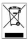
Do not dispose electric tools with domestic waste. In accordance with the European Directive 2012/19/EU the disposal of electrical and electronic equipment and its implementation as national law, electric tools that are no longer serviceable must be collected separately and utilised for environmentally compatible recycling.
service@rothenberger.com - www.rothenberger.com
service@rothenberger.com - www.rothenberger.com
7 Eliminación
Med transportkasse (kg)....43,0
Dimensioner:
Maskine i transportkasse (mm) ....540 x 345 x 355 (LxBxH)
3 Enhedens funktion
service@rothenberger.com - www.rothenberger.com
7 Ártalmatlanítás
natural_image
Blank grid paper with uniform gray squares on white background (no text or symbols)NOTES
D-65779 Kelkheim / Germany
Telefon +49 6195 / 800 - 0
Telefax +49 6195 / 800 - 3500
info@rothenberger.com