NVR10051 - Surveillance Camera ABUS - Free user manual and instructions
Find the device manual for free NVR10051 ABUS in PDF.

User questions about NVR10051 ABUS
0 question about this device. Answer the ones you know or ask your own.
Ask a new question about this device
Download the instructions for your Surveillance Camera in PDF format for free! Find your manual NVR10051 - ABUS and take your electronic device back in hand. On this page are published all the documents necessary for the use of your device. NVR10051 by ABUS.
USER MANUAL NVR10051 ABUS
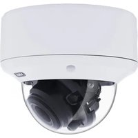
natural_image
Exterior view of a black electronic device with a circular logo on top (no visible text or symbols)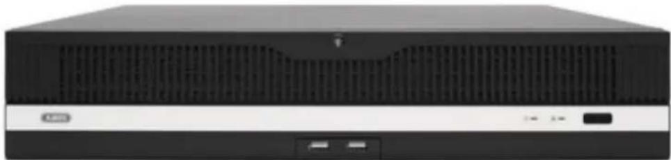
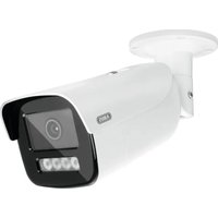
natural_image
Front view of a black desktop computer tower with ventilation grilles and drive slots (no visible text or labels)
All-in-One Stream....62
Urlaub 62
natural_image
Close-up of a textured surface with no visible text, numbers, or symbols on the surface.text_image
2019-12-18 14:08:01natural_image
Exterior view of a black rectangular electronic device with a logo on the front panel (no readable text or symbols beyond branding)
natural_image
Front view of a black desktop computer tower with ventilation grille and drive buttons (no visible text or labels)UK Instructions for local user interface
Original operating instructions in German. Keep for future use.
1) Declaration of Conformity 80
2) First steps / Setup wizard 81
3) Live view....84
Main menu 85
Camera menu 86
Camera command 86
Display menu 86
4) Playback....87
Camera selection 87
Calendar 88
Camera command 88
Playback control....89
Preview images 89
Time representation Timeline 89
Filter timeline 90
Timeline control 90
5) File Management....91
Saved search 92
Event search: 92
Video / Image search....92
Export search results....93
6) Smart Analysis 93
Smart search: 94
Facial image library / face database: 94
Smart event settings: 95
Detection setting: 97
Intelligent report: 97
7) Camera settings 98
Camera 99
Network overview 99
Connect camera via PoE.... 101
Display 104
Privacy Mask.... 105
Video Parameters 105
Event.... 106
Normal event....107
8) Storage settings 109
Schedule 109
Recording video (recording schedule).... 109
Extended 110
Recording image (capture).... 110
Storage medium.... 112
Add network drive.... 113
SSD management.... 113
Storage mode 115
Mode: Contingent 115
Mode: Group 116
Automatic backup (to USB/eSATA) 117
Advanced settings.... 118
9) System settings.... 120
General 120
Users.... 122
Add user....123
Change / edit user 123
Delete user 124
Live View parameters.... 124
Reporting per user.... 124
Network.... 126
TCP/IP 126
DDNS 127
PPPoE....128
NTP 128
NAT 128
Advanced settings - SNMP.... 129
Advanced settings - E-mail.... 130
Advanced settings - ABUS Link Station.... 131
Advanced settings- Additional settings.... 132
Live view 133
General.... 133
Layout / Adverts 134
Decoding performance & network bandwidth 134
All-in-One Stream.... 135
Holidays 135
10) Maintenance 136
System info 136
Logbook 136
Import / Export 137
Update 137
Reset.... 138
Network....138
Hard disc function 139
System maintenance.... 140
Advanced settings.... 140
1) Declaration of Conformity
ABUS Security Center hereby declares that the enclosed product fulfils the following guidelines that apply to the product:
EMC Directive 2014/30/EU
Low Voltage Directive 2014/35/EU
RoHS Directive 2011/65/EU
The complete EU Declaration of Conformity can be obtained from the following address:
ABUS Security Centre GmbH & Co KG
Linker Kreuthweg 5
86444 Affing
GERMANY
www.abus.com/product/Artikelnummer
("Article number" in the link is identical to the article number of the enclosed product)
2) First steps / Setup wizard
After starting the NVR for the first time, a secure password must be assigned for use. Activation can be carried out locally on the device via HDMI/VGA or via the web interface or ABUS CMS software. After successful activation, the assigned password is valid for the administrator access "admin".
The "Export GUID" function is used to specify whether the GUID file should also be exported and created. This file can be used to reset the password (e.g., forgotten password) later. However, there are other ways to reset the password. => See the next step
In the "Create default password for the channel" field, you can enter a password that the NVR will automatically use for adding / activating the network cameras.
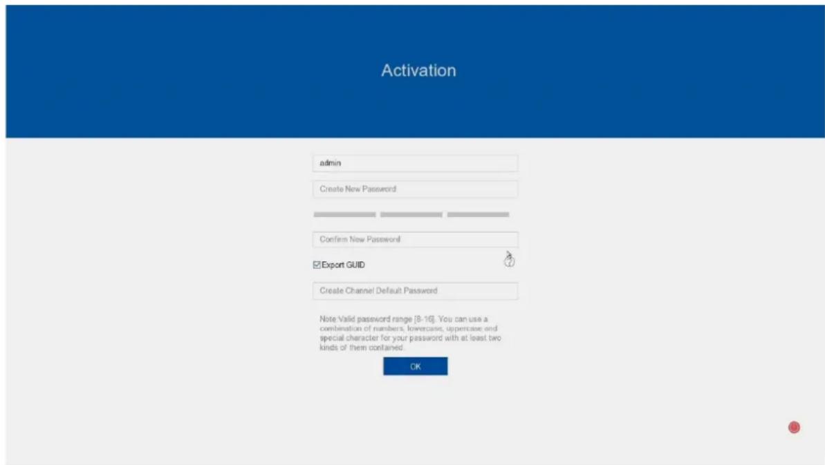
text_image
Activation admin Create New Password Confirm New Password ✓ Export GUID Create Channel Default Password Note Valid password range [8-16]. You can use a combination of numbers, lowercases, uppercase and special character for your password with at least two kinds of them contained. OKReset password
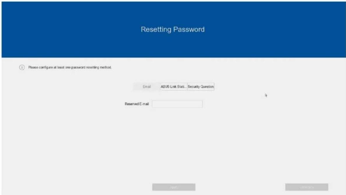
At least one method for resetting the password must be selected.
1) Reserved e-mail: Please enter an e-mail address which will be contacted for recovery in the event of a forgotten password.
2) ABUS Link Station App: Please install the ABUS Link Station Lite App on your smartphone first. Then follow the instructions on the NVR screen and assign a verification code. This will be requested when the app is added. You can view the live images and recordings of the NVR via the app. The "Reset password" function is also available.
You can activate/deactivate the connection with the app at any time, even retrospectively. The app is not absolutely necessary for use and setup.
3) Security questions: Set 3 personal security questions with which it can be reset at a later date
If you are unable to reset the password despite these methods, please contact our technical support.
text_image
Resetting Password ① Please configure at least one password resetting method. Email ABUS Link Status... Security Question Reserved E-mail Next CancelButton
text_image
Wizard 1 Date and Time Setup 2 Network Setup 3 Hand Dial 4 Camera Setup Time Zone (GMT+01:00) Amsterdam, B Date Format DD-MM-YYYY System Date 26-09-2024 System Time 09:38:02 Enable Wizard Next ExitThe setup wizard will then guide you through the necessary basic system settings. The recorder is then basically set up for recording and monitoring.
3) Live view
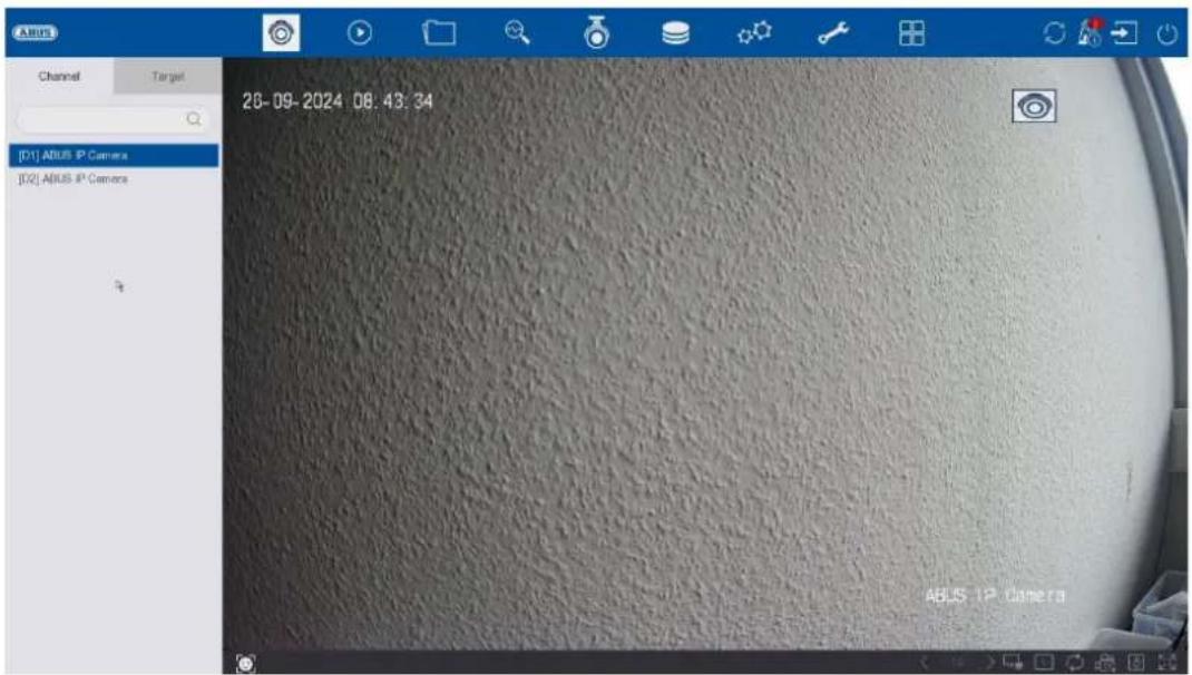
text_image
ABUS Channel Target [D1] ABUS IP Camera [D2] ABUS IP Camera 26-09-2024 08:43:34 ABUS IP CameraThe live view starts automatically when the device is switched on.
This view offers the option of displaying or executing live images and camera commands from all connected cameras on the recorder.
- By double-clicking the left mouse button, you can display the respective camera image as a full screen or switch back to the original view.
- By clicking the right mouse button, you can hide and show the menu structure to display only the respective camera layout as a full screen.
The live view is divided into the following functional areas:
| Main menu Selection of the configuration and operating menus | |
| Camera menu Selection and search for cameras or display of various analysis functions | |
| Camera command | Selection of camera commands and actions for the selected camera |
| Display menu Controlling the view on the local monitor | |
| Recording status | The current recording status is always displayed in the live image (top right) in the form of a coloured R ("Record"). Each video channel can have one of the following three statuses: |
| No symbol No recording programmed, no hard disc available, no event | |
 Event alarm (on movement, alarm input or VCA) Event alarm (on movement, alarm input or VCA) | |
 Recording started Recording started | |
Main menu
 | Switches to the live view |
 | Switches to the playback view |
 | Switches to the file search |
 | Switches to intelligent analysis |
 | Switches to the menu for camera settings |
 | Switches to the menu for memory settings |
 | Switches to the menu for system settings |
 | Switches to the menu for maintenance settings |
 | Switches to the menu for special application modes (depending on the camera/door intercom system used) |
 | Opens the logbookAll interactions and events are recorded in the logbook. Entries can be filtered and displayed here according to specific criteria. |
 | Backup. All active export downloads are displayed here. |
 | Here you can log out of the NVR or restart or shut down the system. |
Camera menu
Camera command
 | Creates an instant image | ||
 | Starts playback of the last 5 minutes | ||
 | Opens the PTZ control | ||
 | Opens the digital zoom | ||
 | Switches audio on / off | ||
 | Opens the display priority | ||
 | Displays information about the video stream | ||
 | Starts / stops recording, ATTENTION: This function overwrites the existing recording schedules. | ||
 | Opens a menu for changing views when using fisheye cameras | ||
 | Shows or hides the detection frames/lines of the VCA detections in the live image. | ||
 | Switches between stream 1 (M = Main) and stream 2 (S = Sub) | ||
 | Switches 3D positioning on / off |
Display menu
 | Switches between view pages |
 | Switches to the second monitor |
 | Opens the selection of camera layouts |
 | Starts / ends the sequence display |
 | Starts / stops the recording of all cameras |
 | Shows or hides the detection frames/lines of the VCA detections in the live image. |
 | Opens and closes the full-screen view |
4) Playback
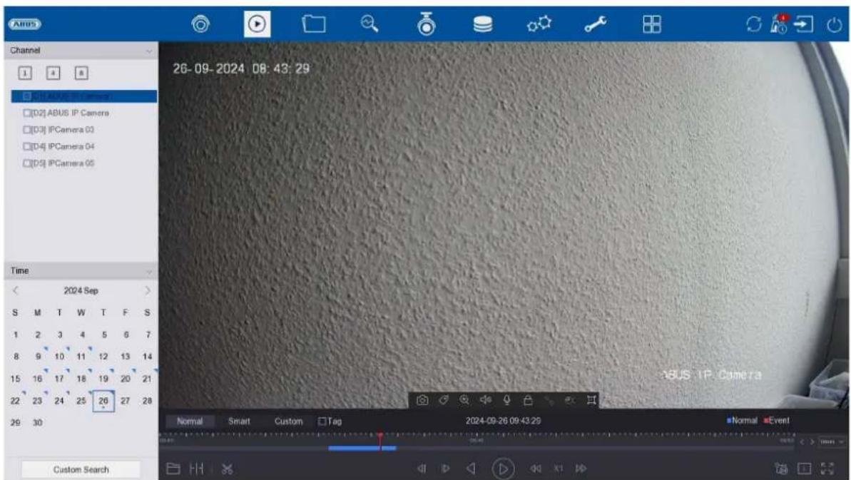
text_image
Channel 1 4 8 □(D1) ABUS IP Camera □(D2) ABUS IP Camera □(D3) IPCamera 03 □(D4) IPCamera 04 □(D5) IPCamera 05 Time < 2024 Sep > S M T W T F S 1 2 3 4 5 6 7 8 9 10 11 12 13 14 15 16 17 18 19 20 21 22 23 24 25 26 27 28 29 30 Custom Search 26-09-2024 08:43:29 Normal Smart Custom Tag 2024-09-26 09:43:29 Normal EventPlayback enables the recorded video data from cameras to be played back on the recorder.
The playback view is divided into the following functional areas:
| Camera selection | Selection of the cameras to be played back. |
| Calendar Selection of the date of the recorded data. | |
| Camera command | Selection of camera commands and actions for the selected camera. |
| Playback control | Control and interaction during playback. |
Camera selection
The camera list is used to select the recorded camera archives on the recorder. Several cameras can be played back simultaneously by clicking on the selection fields in the list.
In the search field above the camera list, you can search for a specific camera name (case-sensitive). You also have the option of clicking on "Select all cameras" or "Select individual cameras".
Calendar
In the calendar, you can directly select the day for the recording to be searched.
Click on "Customised search" to open a new window with criteria and filters to help you narrow down your search.
| Time | Selection of a predefined or self-defined time period |
| File type Select | whether to search for videos or images |
| Marking | If markers have been created, you can search for the name of the marker here |
| File status | Selection of whether the file is "locked" or "unlocked" |
| Event type | Select whether to search for a specific event type. E.G: Motion detection |
| Identification no. & region/country | If a compatible licence plate camera is used, you can search for a specific licence plate here |
The search settings can be saved by entering a name and clicking on the "Save" button. These can be called up and executed in the menu on the left-hand side.
Camera command
 | Creates an instant image |
 | Creates a marker for the current playback position. Markers can be called up and played back directly via the "Marker" playback type. |
 | Opens the digital zoom |
 | Switches audio on / off |
 | The recording file of the current playback position is locked. A locked file is not overwritten by the ring buffer. |
 | Opens the smart search. The respective event type must be activated in order to use the smart search. (motion detection, tripwire, intrusion detection) |
 | Opens a menu for changing views when using fisheye cameras. |
 | Shows or hides the detection frames/lines of the VCA detections in the live image. |
Playback control
Then click on the timeline to start / resume playback at the desired time. Recordings are indicated by coloured bars in the timeline. The colour coding is as follows:
| Continuous recording | |
| Event recording (motion, alarm input, VCA) | |
| Smart search (depending on the filter) |
Preview images
This function allows you to get a quick overview. Position the mouse pointer on the timeline to display nine preview images for the selected time.
Time representation Timeline
The default setting for the display range of the timeline is 20 minutes. This means that the last 10 minutes before and the next 10 minutes after the current playback time are displayed on the timeline. The scaling of the timeline can be set in the following steps:
5 minutes, 10 minutes, 20 minutes, 1 hour, 2 hours, 4 hours, 8 hours, 12 hours, 16 hours, 20 hours, 1 day.
Filter timeline
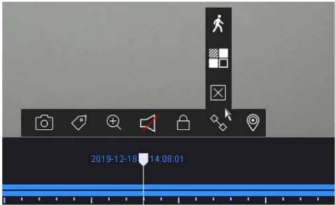
text_image
2019-12-18 14:08:01Four different filters are available to simplify the search for specific recordings. The display of the timeline is also always adapted.
| Duration Displays all permanent recordings | |
| Smart | Displays all recordings that were triggered by a VCA function, e.g. TripwireExisting recordings can be searched for using a VCA function. To do this, click on the icon in the camera command bar.The following three VCA functions are available: TripwireIntrusion detectionMotion detection TripwireIntrusion detectionMotion detection |
| Customised Use the "Customised search" beforehand | |
| Marking Displays added markers in the timeline | |
Timeline control
The following functions are available below the timeline:
 | Opens the menu for playing back recordings from external data carriers |
 | The recordings from the selected camera are shown in the Quad view at different times. This should allow events to be localised more quickly. |
 | Allows you to export video clips quickly and easily. The calendar search option is available. The time of the video clip can also be determined by moving the red brackets on the time bar. |
 | Jumps backwards for 30 seconds |
 | Jumps forwards for 30 seconds |
 | Play and pause the recording backwards |
 | Play and pause the recording forwards |
 | Reduces the playback speed |
| X1 Playback speed | |
 | Increases the playback speed |
 | Switches between stream 1 and stream 2 |
 | Opens the selection of camera layouts |
 | Opens and closes the full-screen view |
5) File Management
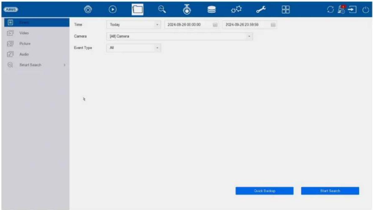
text_image
Agus Event Video Picture Audio Smart Search Time Today 2024-09-26 00:00:00 2024-09-26 23:59:56 Camera [All] Camera Event Type All Quick Backup Start SearchHere you have the following option to search for recordings:
- Event search
• Video (continuous recording)
• Image (snapshot storage) - Audio
• Intelligent search (human/vehicle search)
Saved search
Saved search queries are displayed here and can be called up quickly at a later time.
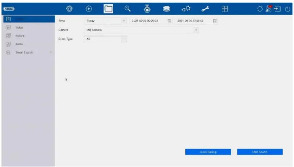
Event search:
| Time | Selection of a predefined or user-defined time period. |
| Camera Select which camera archives are to be searched | |
| File type Select whether to search for videos or images | |
| Event type | Select whether to search for a specific event type, e.g. motion detection. |
Video / Image search
| Time | Selection of a predefined or user-defined time period. |
| Camera Select which camera archives are to be searched | |
| File type/status | Select whether to search for locked or free files. |
All search results can be exported quickly and easily via USB port.
Export search results
Search results can be exported quickly and easily. To do this, select the video or image to be exported (multiple selections are possible) and click on the "Export" button.
When exporting, you have the option of exporting the log file and a video player in addition to the recordings.
Audio: As of today (2024/09), ABUS does not offer any hardware to use this function. Audio recordings can be searched for when using compatible hardware.
Intelligent search:
Man/vehicle:
Here you can explicitly filter by person / vehicle (without verifying which person or which licence plate number) if a camera with this functionality has been integrated into the NVR and a "person" or "vehicle" detection has been configured for the recording.
Face:
This function "Search by Picture" is currently not available.
6) Smart Analysis
text_image
入站 Time Video Picture Audio Smart Search Time Today 2024-09-26 00:00:03 2024-09-26 23:50:59 Camera [AI] Camera Event Type All Quick Backup Start SearchSmart search:
(Note: The identical menu can also be found under "File search")
Here you can explicitly filter for people (no explicit face) / vehicles (no explicit licence plate) if a camera with this functionality has been integrated into the NVR and a "human" or "vehicle" detection has been configured for the recording.
Searching via "Image" is not available at the moment.
Facial image library / face database:
This functions is currently not available.
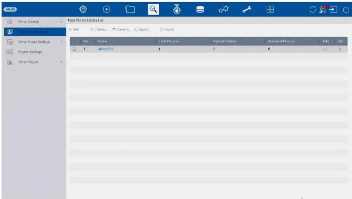
text_image
Face Picture Library List No Name Total Pictures Normal Pictures Aversarial Pictures Edit Det 1 abus1924 1 1 0Smart event settings:
Face recognition:
"Face recognition" and "Face detection" is not available at the moment.

text_image
Smart Search Face Picture Library Smart Event Settings Facial Recognistic Perimeter Protection Vehicles Detection Video Structuralization Other Events Engine Settings Smart Report Camera [D1] ABUS IP Camera Face Capture Face Picture C Enable Face Capture Sensitivity 1 5 3 Arming Schedule Linkage Action Continuous None Edit 0 2 4 6 8 10 12 14 16 18 20 22 24 Mon Tue Wed Thu Fri Sat Sun 1 2 3 4 5 6 7 ApplyFacial image comparison:
This function is not available at the moment.
text_image
Smart Search Face Picture Library Smart Event Settings Model Properties Parameter Protection Vehicle Detection Video Structuralization Other Events Engine Settings Smart Report Camera: 10115624-8000000000000000000000000000000000000000000000000000000000000000000000000000000 Face Capture: 1.1.1.1.1.1.1.1.1.1.1.1.1.1.1.1.1.1.1.1.1.1.1.1.1.1.1.1.1.1.1.1.1.1.1.1.1.1.1.1.1.1.1.1.1.1.1.1.1.1.1 Mode: Face Picture Comparison - Enable Face Picture Comparison Alarm Parameters: Aiming Schedule Linkage Succeeded Linkage Failed Comparison Fee: Compare failed Comparison Set: Welcome Library Name Edit Similarly about1924 Enable Alarm Output Pulse ApplyVCA functions (perimeter protection)
The VCA perimeter detections are also configured and defined for all cameras in the "Smart event settings" menu. Depending on the camera model used, the VCA functions "Trip-wire", "Intrusion detection" and other special functions (licence plate recognition via ANPR camera, thermal camera functions) are available here.
Note: Different VCA functions are available depending on the camera used. For detailed instructions on how to use the function, please read the camera manual. The functions listed here are the most commonly available VCA functions:
text_image
ABUS Smart Search Face Picture Library Smart Event Settings Facial Recognition Perpendicular Detection Vehicle Detection Video Structuralization Other Events Engine Settings Smart Report Camera [D:\ABUS IP Camera Enable AI by NVR System Delay: Intrusion Region Entrance Region Exiting Enable Trignire Detection Detection Area Settings Aiming Schedule Linkage Action Aiming Area 1 Direction A<=B Sensitivity 1 100 50 Detect: Human Vehicle Detection Ar Draw Area Clear All Size Filter Max. Size Min. Size| Tripwire Detection | The Tripwire function triggers an event when an object moves over a virtual line in one or both directions. |
| Intrusion Detection | The Intrusion Detection function triggers an event if an object remains in the area to be monitored for longer than the set time. |
| Scene Change Detection | This function triggers an event if the image content changes significantly. Rotation of the camera can therefore be recognised. |
Detection setting:
Detection mode:
This menu is used to select which detection type the NVR should use.
- Face recognition (Not available at the moment)
• Perimeter protection (Not available at the moment) - Motion detection 2.0 (motion detection with human/vehicle detection)
Note: This function is not normally used in conjunction with ABUS network cameras, as the current ABUS network cameras already support the various detection types themselves and therefore do not need to be analysed by the NVR itself.
The following table provides an overview of the maximum number of channels for which the NVR can perform detection itself, depending on the recorder model and desired detection type:
| ABUS model | Motion detection |
| NVR10011 | 8 |
| NVR10021 | 8 |
| NVR10021P | 8 |
| NVR10031 | 16 |
| NVR10031P | 16 |
| NVR10041 | 32 |
| NVR10051 | 32 |
Face categorisation:
This function is not used at the moment.
Intelligent report:
Attention: Only in conjunction with cameras (e.g. ABUS Fisheye) that support people counting / heat map (heat map). The respective function must be activated in the camera itself and saved on the camera's microSD card.
People counting
Select the camera with the people counting function. Use the calendar to select the desired period and select the desired report type. (Daily, weekly, monthly, annual report). The incoming and outgoing persons are now displayed in the statistics. This can be exported to an external storage medium using the export function.
Heat map
Select the camera with heat map function. Use the calendar to select the desired date and select the desired report type. (Daily, weekly, monthly, annual report). Click on "Counting" to display the heat map image. This can be exported to an external storage medium using the export function.
7) Camera settings
text_image
ABUS Camera Show password + Custom Add × Delete Import/Export More Settings Enter a keyword No Delete Sta Security IP Address Edit Upgrade Camera Name Protocol Device Management Set D1 × Weak Pa... 192.168.0.42 ↑ ABUS IP Cam... ABUS PCB385... 8000 IPC D2 × Weak Pa... 192.168.0.23 ↑ ABUS IP Cam... ABUS PCB445... 8000 IPC (Number of Unaddle... + Add Refresh Activate Enter a keyword No Status Security IP Address Edit Device Modi Protocol Management Serial No Fmmw 1 Active 192.168.0.31 Off IPCB78521 ABUS 10074 IPCB785212021... V5.7.1 2 Active 192.168.0.244 Off IPCB64510B ABUS 45003 IPCB64510B201... V5.5.5 3 Active 192.168.0.13 Off IPCB64521 ABUS 10043 IPCB645212021... V5.7.3 4 Active 192.168.0.11 Off IPCB74521 ABUS 12023 IPCB745212021... V5.7.1 5 Active 192.168.0.44 Off IPCB44561A ABUS 8000 IPCB44561A202... V5.7.2Camera management takes place in this menu. Furthermore, basic camera settings can be made.
Camera
| ☐ | Show password: Displays the passwords of the cameras in plain text |
 | Add camera manually |
 | Delete camera |
 | Import / export camera list |
 | Further settings:ProtocolHere you can create a user-specific RTSP profile. This profile can then be selected when adding a camera.Protocol: Select the profile to be definedName: Freely selectable nameStream:○ All values below "Stream 1" are used for stream 1 (live+recording).○ All values below "Stream 2" are used for stream 2 (multiple live display).Stream 2: Activates stream 2Type: RTSPTransfer protocol: Use the Auto setting if there are no special requirements.Port: Enter the RTSP portPath: Specification of the RTSP streaming path on the network cameraTypical structure of an RTSP streaming path:rtsp://192.168.0.1:554/video.h264Camera default password managementHere you can change the default password (assigned during the initial setup in the setup wizard). This is used for the QUICK-ADD function in the camera menu. In addition, "Inactive" cameras can be activated with this password. |
Network overview
Click on the " " button at the bottom of the menu to display an overview of all cameras in the network. This display is fixed by clicking on the "Lock" icon.
Select the desired cameras to "Activate" them or "Add" them to the NVR.
text_image
Add IP Camera (Custom) No | Sta... | Security | IP Address | Device Model 1 - ✓ Active 192.168.0.244 IPCB64510B 2 ✓ Active 192.168.0.31 IPCB78521 3 ✓ Active 192.168.0.13 IPCB64521 IP Camera Address 192.168.0.244 Protocol ABUS Management Port 45003 Transfer Protocol Auto User Name installer Password Use Channel Default... Enable IP Camera T... Use Default Port ✓ Verify Certificate Search Continue to Add AddHere you can manually add network cameras by entering the IP address, protocol, port and user ID or edit the settings of cameras that have already been added. Network cameras from other manufacturers, ONVIF-compatible cameras and RTSP profiles can also be added via this menu.
Select a camera from the list and add/change the corresponding parameters if necessary.
Alternatively, you can add cameras by clicking on the buttons at the top of the menu.
| IP address IP address of the camera | |
| Protocol | Manufacturer Communication protocol. For cameras from ABUS, please select ABUS as the protocol. |
| Port Communication port of the camera (usually 8000 for ABUS network cameras) | |
| Transmission protocol | Auto (recommended), UDP, TCP |
| User name User name of the camera's admin account | |
| password Password of the camera admin account | |
| Use the default password for the camera | Use default password (was assigned during the initial setup in the setup wizard) |
| Use standard port | Use standard port (8000) (was assigned during the initial setup in the setup wizard) |
| Check certificate | The certificate is a form of identification for the camera that allows more secure camera authentication. When using this function, the IP camera certificate must first be imported into the NVR (see Network settings). |
Connect camera via PoE
The PoE NVR10021P and NVR10031P have integrated PoE ports via which ABUS network cameras can be connected directly. (See compatibility list).
Please connect the individual cameras to the PoE ports step by step and wait until the respective camera has the "ONLINE" status and an image can be seen.
Attention:
The automatic addition via PoE port only works properly if the camera is set to factory settings inactive. The NVR automatically activates the camera with the standard IP camera password. If the camera has already been activated, the correct password must be entered in the NVR afterwards.
The cameras are automatically assigned a fixed IP address by the NVR.
The web interfaces of the cameras connected to the PoE port can also be opened via the NVR's web interface. (Configuration / System / Camera management).
The configuration options for the integrated PoE ports can be found locally on the device under "Camera" / "PoE settings".
A) Configure PoE power supply
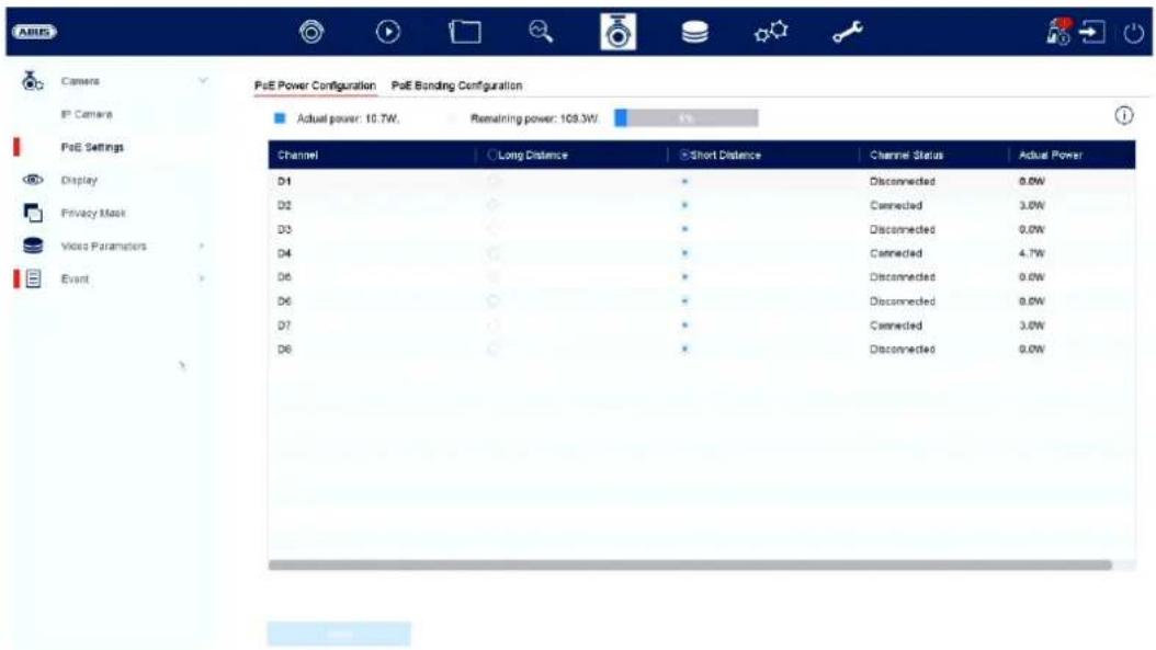
text_image
Pse Power Configuration Pse Bonding Configuration Actual power: 10.7W. Remaining power: 109.3W. Channel Long Distance Short Distance Channel Status Actual Power D1 * Disconnected 0.0W D2 * Connected 3.0W D3 * Disconnected 0.0W D4 * Connected 4.7W D5 * Disconnected 0.0W D6 * Disconnected 0.0W D7 * Connected 3.0W D8 * Disconnected 0.0WChannel: The number of available slots is displayed here
Long-distance transmission: You can activate long-distance transmission here
Short-distance transmission: You can activate short-distance transmission here
Channel status This shows which cameras are connected.
Info display:
Current power The power consumption of all connected cameras is added together here
Power still available The unused power is displayed here
B) Configuring the PoE connection
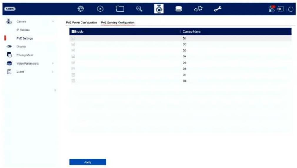
text_image
P&E Power Configuration P&E Sending Configuration Enable Camera Name D1 D2 D3 D4 D5 D6 D7 D8 ApplyHere you will find a list in which you can activate/deactivate the PoE channels.
If you deactivate the "PoE ports", you can add network cameras in the "IP camera" menu in the normal way.
Display
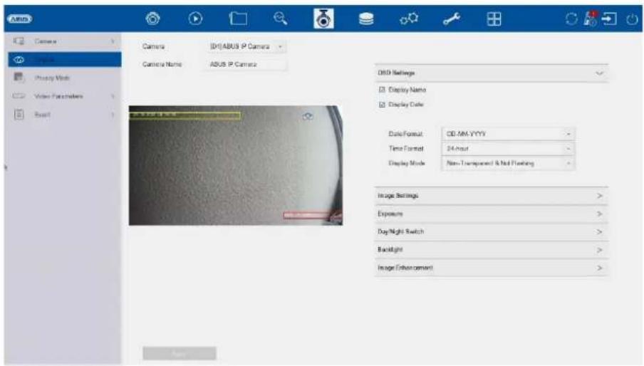
text_image
AUSU Camera Camera Name [0]ABUS IP Camera ABUS IP Camera OBD Settings Display Name Display Color Date/Format: CD:MM-YYYY Time Format: 24 Hour Display Mode: Non-Transparent & Not Floating Image Settings: Exposure: Day/Night Switch: Backlight: Image Enhancement:Here you have the option of making individual settings for the camera display for each camera. The camera name and date & time can be positioned directly in the displayed live image.
Please note: The selection of setting options may vary depending on the camera model used.
For more information on the settings, please refer to the camera operating instructions.
| Camera Select the camera to be set | |
| Camera name | You can chan ge the name of the camera here |
| OSD settings | Here you can select what is to be displayed in the camera image and in which format:Name, date, day of the week |
| Image settings | Here you can adjust the brightness, contrast and saturation of the image.Depending on the installation of the camera, it may be necessary to make the following settings:Corridor mode: Rotates the image by 90°Mirror mode: Tilts or mirrors the image. |
| Exposure You can ad just the camera's exposure time here | |
| Day/night switching | Here you can adjust the behaviour of the day/night switchover and activate/deactivate SMART-IR. |
| Backlight You can ad just the WDR behaviour of the camera here | |
| Image enhancement | You can adjust the camera's digital noise reduction (DNR) here |
Privacy Mask
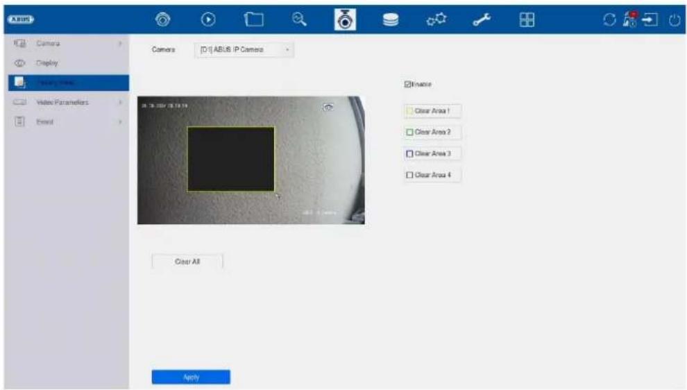
text_image
A BUS Camera Display Drawing Camera Video Parameters Email Camera [D:\] ABUS IP Camera Kinase Clear Area 1 Clear Area 2 Clear Area 3 Clear Area 4 Clear All ApplyHere you can create up to 4 privacy zones per camera. By clicking on the "Activate" checkbox, you can create and delete the privacy zone directly in the displayed live image.
Video Parameters
text_image
XABUS Camera Display Privacy Mask Video Parameters Main Stream Sub-Stream Event Camera [D:\JABUS IP Camera Encoding Parameters Stream Type Video Resolution 3840*2160(MPa) Bitrate Type Variable Video Quality Medium Frame Rate Full Frame Max. Bitrate Mode Custom(32-163K) Max. Bitrate(Kbps) 12258 Max. Bitrate Range Room 15246-163K4(Kbps) Video Encoding H.264 I Frame Interval 50 Enable H.264+ Note Different frame rate of continuous and event recording may cause problems in the exported AVI video. Main Stream(Event) Video 3840*2160(MPa) Variable Medium Full Frame Custom(32-163K) 12258 15246-163K4(Kbps) H.264 39Here you can adjust the video parameters for stream 1 (main stream) and 2 (substream).
Note: For more information on the settings, please refer to the camera operating instructions.
Important note: As soon as the camera has been taught into the NVR and connected, the NVR takes over the configuration (deep integration). Changes to video/audio stream adjustments and all detection settings (motion detection, VCA etc.) should only be programmed via the NVR.
Event
text_image
ANSYS Camera Display Privacy Mask Video Parameters Event Motion Detection Video Tampering Video Loss Alarm Input Alarm Output Exception Camera USB ARSLS IP Camera Enable AI by NVR Enable Area Among Schedule Linkage Action Sensitivity 0 100 60 Detects Human Vehicle Draw Area Clear ApplyIn the "Event" menu, you specify which reactions are to be triggered in the event of an incident (e.g. motion detection).
For some events, it is necessary to define an area, sensitivity and schedule (when this event should be monitored). You can also select the following "Link action" as a reaction to the event.
| Full screen monitoring | Displays the triggered camera as a full screen on the local monitor. (Configuration of the full screen output under "System" / "Live view") |
| Audio warning Starts | a warnin g tone on the recorder |
| CMS / Link Station Push | Sends a push message to the ABUS CMS or ABUS Link Station app |
| Send e-mail Sends an e-mail | (the recipients + SMTP must be set up first) |
| Local->1 Triggers the | local alarm output. |
| Note: The number of alarm outputs varies depending on the NVR model and connected cameras. If an ABUS network camera has its own alarm output, this can also be triggered and integrated via the NVR. |
The "Trigger channel" defines which cameras are triggered and recorded in the event.
Normal event
The following events can be set up in the "Normal event" menu:
text_image
ABUS Motion Detection Video Tampering Video Loss Alarm Input Alarm Output Exception Camera TOP ABUS IP Camera Enable AI by NVR Enable Area Arming Schedule Linkage Action Sensitivity 0 100 60 Detecti... Human Vehicle Draw Area Clear Apply| Motion detection The | recorder only processes motion detection within the camera. |
| If a live image from the camera is displayed in this dialogue, you can configure the camera's motion masks directly. | |
| If neither "Human" nor "Vehicle" is activated, the motion detection function detects every event, including moving trees, shadows, etc. | |
| Note: The displayed settings for motion detection are basic settings. Detailed settings may be offered in the camera's web interface. | |
| Sabotage monitoring | The tamper monitoring function monitors the brightness value of the selected camera. If the lens is covered, the trigger is activated. |
| Video loss The video | loss function monitors the selected camera for image loss. If the camera can no longer be reached via the network, the trigger is activated. |
| Alarm input The alarm | input function monitors the behaviour of the physical and virtual alarm inputs. Alarm inputs from connected ABUS network cameras can also be analysed here. |
| Alarm output The alarm output function defines the behaviour of the physical and virtual alarm outputs. Alarm outputs from connected ABUS network cameras can also be analysed here. |
| Exception The Exception function defines the behaviour of the recorder for warning messages and system events, e.g. channel errors, hard disk errors. |
8) Storage settings
Schedule
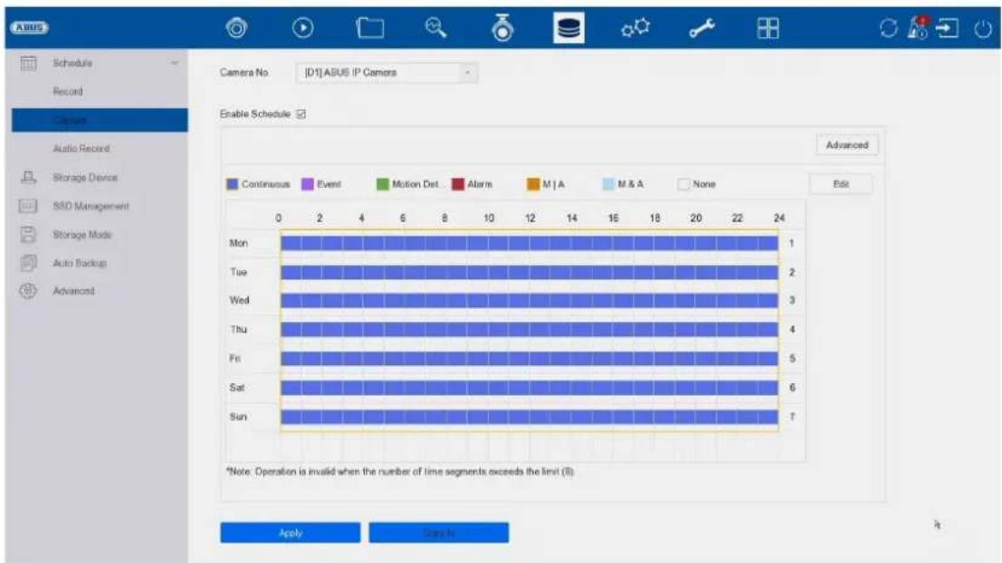
text_image
Schedule Capture Audio Record Storage Device SSU Management Storage Mode Auto Batchup Advanced Camera No: [D:\ADUS P Camera Double Schedule Advanced Continuous Event Motion Det Alarm M/A M.S.A None Edit 0 2 4 6 8 10 12 14 16 18 20 22 24 Non Tue Wed Thu Fri Sat Sun 1 2 3 4 5 6 7 Name CancelIn this menu, you define the schedule and the triggers for recording videos or images.
| Recording | Programme the recording of videos here |
| Capture | Programme the recording of images here |
Recording video (recording schedule)
First activate the schedule, click on a trigger and then hold down the left mouse button and drag in the weekly calendar to define the desired times.
| Duration | Continuous continuous recording |
| Event | The following is recorded for each type of event (VCA events) |
| Movement | It is only recorded when motion is detected |
| Alarm | Recording only takes place for alarm input (local/remote) |
| B | A | It is recorded when motion is detected or when an alarm is received (local/remote) |
| B & A | It is only recorded when motion is detected and an alarm is triggered at the same time |
| None | No recording takes place |
| Edit | Here you can edit the settings in list form |
The following settings can be made by clicking on the "Advanced" button.
Extended
| Record audio | Activates audio recording (if the camera provides an audio signal and the stream is set to "Video & Audio") |
| Pre-alarm | Activate the pre-alarm recording hereNote: Depending on the system configuration and number of cameras, a storage time of up to 10 seconds can be achieved. |
| Post-alarm | Select the duration for the post-alarm storage for event recordings |
| Stream type | Select the stream source for the recording. With "Stream1&2", both streams are recorded |
| Expiry time (days) | Specify how many days the recordings should be kept before they are overwritten |
| Redundant (video/image) | Activates storage for the "Redundant" HDD group (only available if HDD group mode is activated) |
Recording image (capture)
text_image
Schedule Record Camera Audio Record Storage Device SSD Management Storage Mode Auto Backup Advanced Camera No: [D1] ASUS IP Cameras Enable Schedule Advanced Continuous Event Motion Det Alarm M | A M & A None Edit Mon 1 Tue 2 Wed 3 Thu 4 Fri 5 Sat 6 Sun 7 0 2 4 6 8 10 12 14 16 18 20 22 24 *Note: Operation is invalid when the number of time segments exceeds the limit (8): Apply CreateFirst activate the schedule, click on a trigger and then hold down the left mouse button and drag in the weekly calendar to define the desired times.
| Duration | Permanent storage of snapshots |
| Event | A snapshot is saved for each type of event (VCA events). |
| Movement | An image is only saved when motion is detected |
| Alarm | An image is only saved for alarm input (local/remote) |
| B | A | An image is saved when motion is detected or when an alarm is received (local/remote) |
| B & A | An image is only saved if motion is detected and an alarm is triggered at the same time |
| None | No recording takes place |
| Edit | Here you can edit the settings in list form |
The following settings can be made by clicking on the "Advanced" button.
You will find the following setting options under "Advanced":
| Parameter type | Displays the setting for permanent and event snapshots |
| Resolution | Select the image resolution. If "AUTO" is selected, the original resolution of the camera is used, i.e. also higher resolutions such as 4MPx or 8Mpx. |
| Picture quality | Select the image quality |
| Interval | Select the interval to be triggered |
| Detection delay | Adjustable from 0 to 5 minutes |
Storage medium
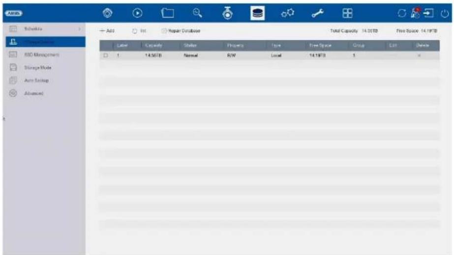
text_image
AABB Schedule Add Edit Repair Database Total Capacity 14.00TB Free Space 14.19TB Balance Capacity Status Properties Type Free Space Group Edit Delete ISO Management Storage Mode Auto Backup Advanced 1 14.56TB Normal R/W Local 14.19TB 1Here you can configure local or network-based storage media and view their status.
| Add | Add network drive |
| Initialise | Initialise (format) memory |
| Repair database | Rebuilds all databases, the files are not deleted. |
| Total capacity | Displays the total memory space |
| Available memory | Displays the total free memory space |
Attention: Before you can make recordings with the device, the built-in hard drive must be "initialised". All hard disk data will be deleted during initialisation!
| No. Number of | built-in hard drives / added NAS drives |
| Capacity | Displays the storage space in GB |
| Status Shows the current status of the hard drives: | |
| Not initialisedNormalFaultySleeping (=standby) | |
| Properties | Displays the access status of the hard drive:Read only: Write protectionReading/writing: Reading and writing |
| Type Displays the connection type of the hard drive: | |
| Local: Device hard driveNAS: Network hard drive (NFS)IP SAN: iSCSI Volume | |
| Memory | Displays the free memory space |
| Group | Shows which group the hard disc is assigned to |
| Processing | You can change the group assignment and access status hereHDD no.: Internal numbering of the hard disksR/W: In this mode, video data is written to the hard discs and can also be read (default setting)Read only: In this mode, no video data is written to the data carrier. This setting is useful if you want to prevent the data from being overwritten after an event.Redundant: In this mode, video data is saved redundantly on all data carriers with the "Redundant" setting. To do this, the "Redundant" button must be set in the "Recording→ Parameters→ Further settings" menu.Group: Assignment of the hard disk to an HDD group |
| Delete | Deactivate / activate hard drive |
Attention: If only one hard disc is installed and this has the status "Read only", the device cannot make any recordings!
Add network drive
Click on "Add" to add a network drive.
Attention: A separate volume/partition must be used on the NAS for each NVR, as multiple use of a partition/folder/volume could lead to problems.
Note: During initialisation / formatting of the NAS storage, the NVR reserves the entire available storage space with "placeholder files".
| Network drive Choose between 8 network drives. | |
| Type | • NAS: Your network storage must support the NFS file system for this setting.• IP SAN: Your network storage must support the iSCSI protocol for this setting. |
| IP address Enter the IP address of the network stora ge device here. | |
| Directory Click on "Search" to select the path or enter it directly. | |
SSD management
The recorder has an integrated small memory.
The faces created under "Face data library/face database" are saved here. The face database can be completely formatted and restarted here.
This function is not available at the moment.
ATTENTION: All saved images of created faces will be deleted.
No video/audio data is recorded on this integrated memory!
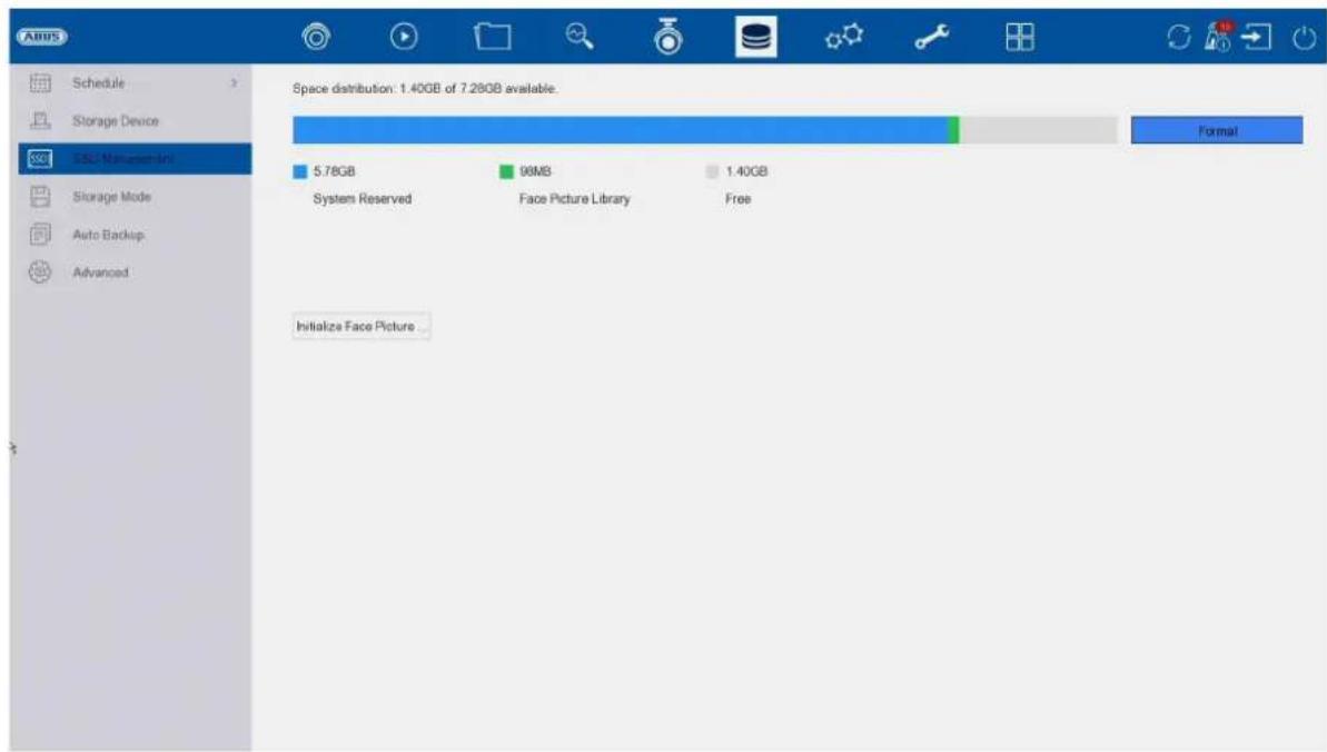
text_image
Adobe Schedule Storage Device SSL: Microsoft Storage Mode Auto Backup Advanced Space distribution: 1.40GB of 7.28GB available. 5.78GB 98MB 1.40GB System Reserved Face Picture Library Free Initialize Face Picture...Storage mode

text_image
ABS Schedule Storage Device S3D Management Save To Work Auto Backup Advanced Mode Quote Group Device Type IPC Video Camera (D1)ABUS IP Camera Used Record Capacity 212.00GB Max. Record Capacity (GB) 0 Picture Used Picture Capacity 1254.00GB Max. Picture Capacity (GB) 0 Free Quote Space/Total Disk Space: 14902GB/14902GBIn this menu, you set the storage mode of the recorder. Two different storage modes are available to either distribute video data to all hard drives or to enable specific write operations to individual data carriers.
Mode: Contingent
In this mode, the video data is written distributed over the total number of all connected data carriers.
| Camera Select the camera | |
| Video memory used | Currently used video memory on the data carrier network |
| Used image memory | Currently used image memory on the data carrier network |
| HDD capacity (GB) | Shows the total storage space in GB |
| Reserved memory "Video" | Set the maximum recording size for video on the data carrier network per camera |
| Reserved memory "Pictures" | Set the maximum recording size for images on the data carrier network per camera |
Mode: Group
In this mode, the video data can be written specifically (also redundantly) to selected data carriers. The data carriers are organised in "groups" for this purpose. A group must contain at least one HDD.
| Record to HDD group | Select the HDD group |
| Camera | Select which cameras should record on the currently selected group |
Note: To make settings for the HDD group, click on "Edit" in the "Storage\Storage device" menu for the respective hard drive.
Automatic backup (to USB/eSATA)
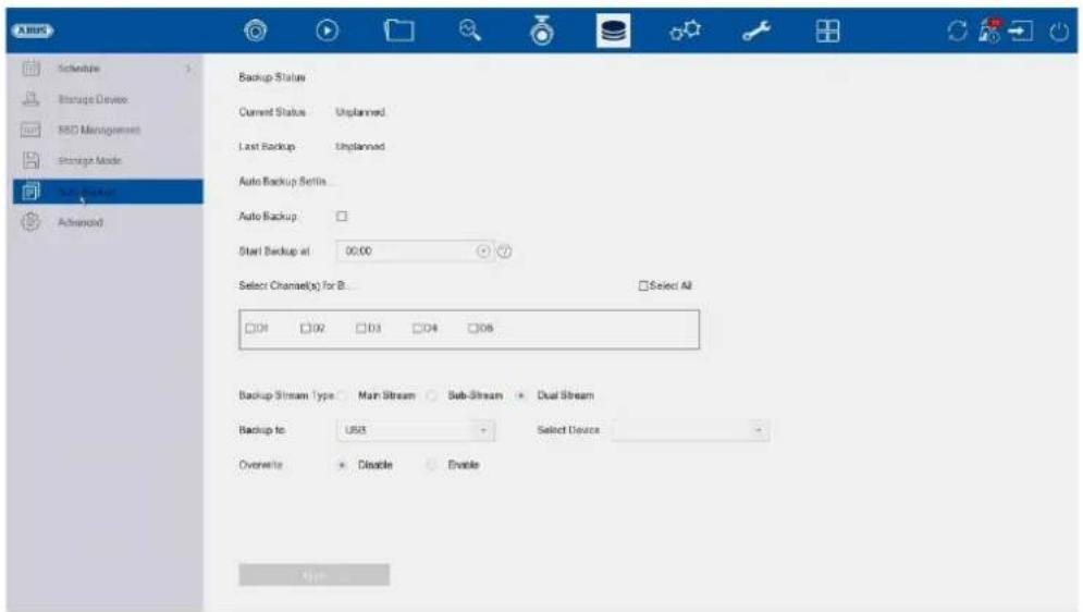
text_image
A BUS Schedule Storage Device MSD Management Storage Mode Auto Backup Advanced Backup Status Current Status Unplanned Last Backup Unplanned Auto Backup Setis... Auto Backup : Start Backup at 00:00 Select Channel(s) for B... □ Select All □04 □02 □03 □04 □05 Backup Stream Type Main Stream Sub-Stream Dual Stream Backup to US$ Select Device Overwrite Disable Enable HelpYou can set up the automatic backup here. The last 24 hours are automatically exported to a USB / eSATA device.
| Backup status The progress of the backup is displayed here | |
| Current status Displa ys the current status. | |
| Last backup This shows whether the last backup was successful | |
| Auto Backup This can be used to set the backup to be performed automatically every day | |
| Start time Here you enter when the backup should start | |
| Channels for the fuse Here you can select the camera channel for which the backup is to be made | |
| Backup Stream Type Here you can select the stream for which the backup is to be made | |
| Goal The device type to be used for the backup is selected here | |
| Select device Select the connected device here. USB or eSATA(if available) | |
| Overwrite This option sets whether the existing data of the connected device may be overwritten |
Advanced settings
Here you can make general settings for all installed hard drives.
| Overwrite | Specify whether older recordings should be overwritten when the hard disc is full. |
| eSATA | Only 1x eSATA output is available. |
| Utilisation | Specifies the use of the sSATA port. Either as a normal storage hard drive or for exporting data. |
| HDD sleep function | When this function is activated, hard disks that are idle go into standby mode. |
| RAID | Activate the integrated RAID controller here (NVR10041/NVR10051 only). After activation, the system is restarted. Only then is the RAID menu available for configuring the RAID array. |
| Save VCA data | When this function is activated, the VCA data is also recorded. Caution: This results in higher data consumption per camera. This function is deactivated by default. |
RAID:
In this menu, you can create a RAID array to record the video data on the recorder.
Attention:
RAID is a software RAID function. This means that the RAID data is managed by the integrated CPU of the recorder. If the function is activated, the INPUT bit rate of the NVR is reduced by approx. 40%.
Physical data carrier:
This view shows a list of all data carriers connected to the NVR. The following options are available for further configuration:
| Quick configuration | Automatically creates a RAID array of all free data carriers. |
| Create | Manual creation of a RAID array. The following RAID types can be used: RAID0, RAID1, RAID5, RAID10. |
| Hotspare | Free data carriers that are not assigned to a RAID array can be defined as "Hotspare". These data carriers are not initially used by the system. If a data carrier error occurs in a RAID array, the hot spare data carrier is immediately activated for use. |
Hint
If you would like more information on the use of RAID, please refer to the relevant specialist literature.
Array:
This view shows the current status of the RAID array. The following actions can be performed:
| Re-Build Carry out a manual rebuild of the array. This rebuilds the data structure of the RAID array. | |
| Delete Delete the RAID array. This makes the data carriers "free" again and they can be reused for RAID configurations. |
9) System settings
All basic device settings are managed in the "System" menu.
Attention: Make sure that the date and time have been set correctly.
Subsequent changes can lead to data loss! Make sure you back up your data in good time.
General
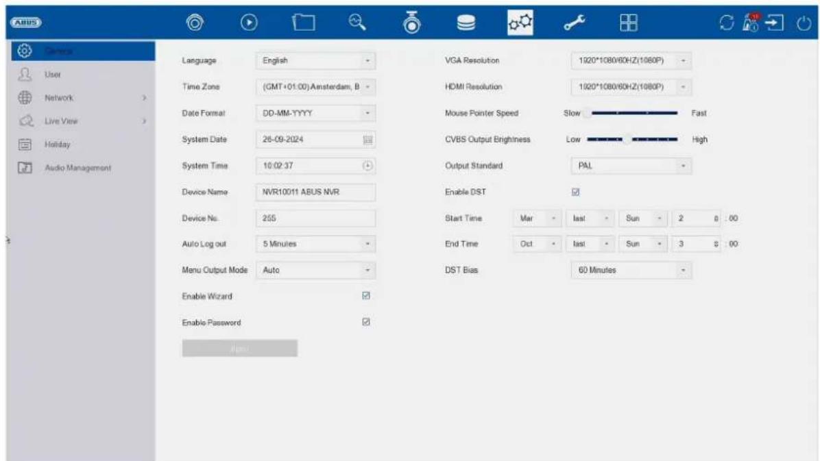
text_image
AUS Language English Time Zone (GMT+01.00) Amsterdam, B Date Format DD-MM-TYYY System Date 26-09-2024 System Time 10:02:37 Device Name NVR10011 ABUS NVR Device No. 255 Auto Log out 5 Minutes Menu Output Mode Auto Enable Wizard Enable Password VGA Resolution 1920*1080/60HZ(1080P) HDMI Resolution 1920*1080/60HZ(1080P) Mouse Pointer Speed Slow Fast CVBS Output Brightness.Low High Output Standard PAL Enable DST Start Time Mar Last Sun 2 8 00 End Time Oct Last Sun 3 8 00 DST Bias 60 Minutes User Network Live View Holiday Audio Management| Language Select the menu language to be displayed | |
| Time zone Select the time zone in which you are located | |
| Date Format Select how the date should be displayed:MM-DD-YYYY, DD-MM-YYYY, YYYY-MM-DD | |
| date Set the current date | |
| Time Set the current time | |
| Device name You can assign a name/description for the recorder here | |
| No. Used to uniquely identify the recorder when using a control panel | |
| Speed of the mouse pointer | Sliding bar, low speed on the left, high speed on the right |
| Car. Deregistration Select the duration after which the menu is automatically closed: Never / 1 ... 30 minutes | |
| Menu display Select the monitor output for displaying the menu. If Auto is selected, the output is determined by the recorder. | |
| Activate assistant Select whether the wizard should appear at system startup | |
| Activate password Select whether a password prompt should appear during local operation. Attention: However, the password must be entered when accessing via the network. | |
| VGA resolution Select the monitor resolution of the VGA output | |
| HDMI resolution Select the monitor resolution of the HDMI output | |
| Speed of the mouse pointer | Select the desired speed of the mouse pointer |
| Activate summer time | Select whether the recorder should switch between summer and winter time. Auto: Recorder changes automatically Manual: Recorder changes based on the set start/end date |
Users
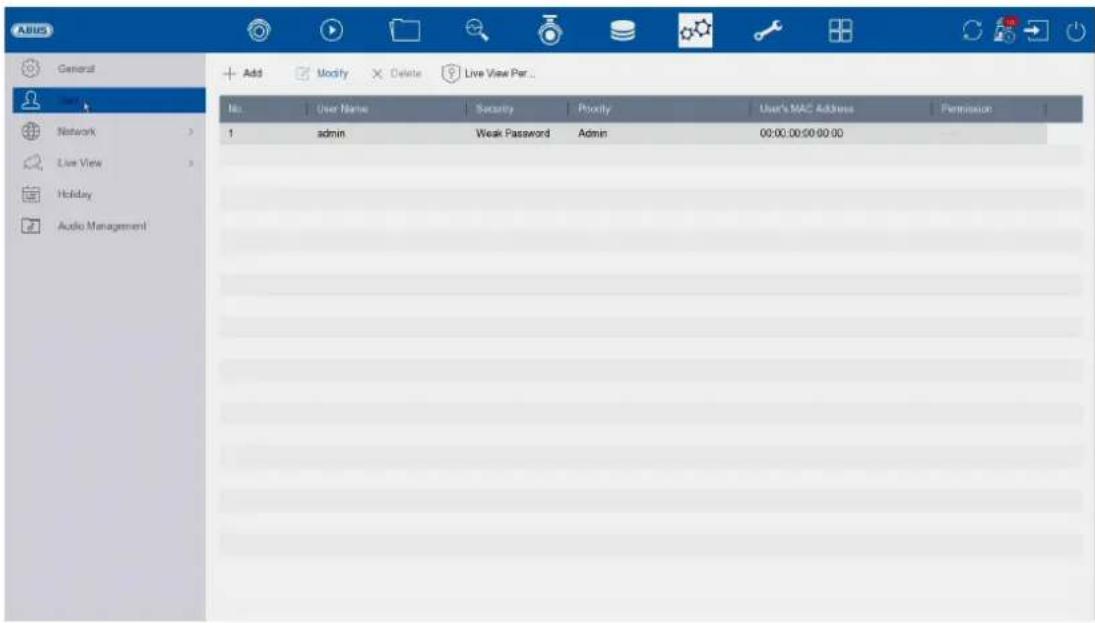
text_image
ABUS General Network Live View Holiday Audio Management Add Modify Delete Live View Per... No User Name Security Priority User's MAC Address Permission 1 admin Weak Password Admin 00:00:00:00:00 adminUser administration takes place in the "User" menu.
 | Add user | |
 | Change user | |
 | Delete user | |
 | Defines which cameras can be seen locally on the "Lock screen" without being logged into the NVR. |
Add user
To add a user, click on the "+" symbol and then enter the administrator password.
| User name Choose a unique name | |
| password Choose a password | |
| Note: change passwords regularly, use combinations of letters, numbers etc., write down passwords in a safe place. | |
| Confirm Confirm the password | |
| User authorisation Select the authorisation level of the user. | |
| IMPORTANT:More rights can be set for theOperatorlevel than for theGuestlevel. | |
| User MAC Here you | can enter the MAC address of the network adapter of the PC used by the respective user. Access for the user is then only possible with this MAC address. |
Change / edit user
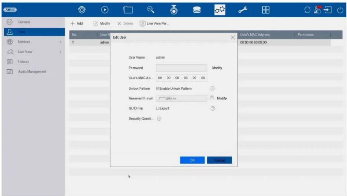
text_image
Anus General User Network Live View Holiday Audio Management No. 1 admin Add Modify Delete Live View Per... Edit User User Name admin Password Modify User's MAC Ad... 00 00 00 00 00 00 Unlock Pattern Enable Unlock Pattern Reserved F-mail 1****@lot.in Modify GUID File Export Security Quest... OK Cancel User's MAC Address Femission 00:00:00 00:00:00To change the settings for a user, first select a user and then click on the "Change" icon.
The following changes can be made:
- User name (not for the "admin" administrator)
- password
- Activate / change release pattern
• MAC address of the user
• Reserved e-mail for password reset
• GUID file for password reset
• Security questions for resetting the password
Reset GUID file for password:
The GUID file can be used to reset the password independently (in addition to other methods).
Attention:
A new GUID file must be created after all changes to user accounts, otherwise the password reset cannot be carried out using this method.
Delete user
To delete a user, first select a user and then click on the "Delete" icon.
Live View parameters
Here you can specify which cameras may or may not be displayed on the HDMI/VGA screen when no user is logged in.
To do this, enter the admin password and then select which cameras are to be displayed in the not logged in status.
Reporting per user
For each user, you can define which rights the user has for local and remote access via the network.
To do this, select the user, click on in the "Authorisations" column and enter the admin password.
| Local configuration | The authorisations in the "Local configuration" tab relate exclusively to configuration settings that are accessible via the local user interface (access via local monitor) |
| Remote configuration | The authorisations in the "Remote configuration" tab relate exclusively to configuration settings that can be accessed via remote applications (browser, app, CMS software) |
| Camera configuration | The authorisations in the "Camera configuration" tab relate exclusively to cameras. Access and operation of cameras (live/playback/export) via remote and local are controlled here |
Network

text_image
AIDS General User Networks Active Advanced Live View History Audio Management TCR/IP DDNS PPPoE NTP NAT Working Mode: 100 MHz (100 MHz) Select NIC: 8.0000 NIC Type: 10V/100V/100N Self-Adaptive IPv4 IPv5 Enable DHCP 61 IPv4 Address: 132 158 8 28 IPv4 Subnet Mask: 255 256 255 . 0 IPv4 Default Gateway: 132 . 158 . 6 . 1 Enable Obtain DNS Se 62 Preferred DNS Server: 192 198.0.1 Alternate DNS Server: 6.6.8.9 MAC Address: No 11 ch Of 9x42 MTU(Bytes) 1500 Main NIC LAN1The complete network configuration of the recorder is carried out in the "Network" menu. The recorder must at least be physically connected to the network using a network cable. To ensure smooth network operation, we recommend continuous Gbit cabling between the recorder, camera and switch.
Note
The correct network settings are essential for integrating network cameras and accessing the recorder using remote software (browser, CMS, app).
TCP/IP
Settings for the local network and selection of the network mode are defined here.
| NIC type Set the transmission speed of the built-in network card here. Select "Self-adaptive" so that the recorder automatically determines the best possible speed. | |
| Activate DHCP Activate the checkbox if you assign the IP addresses in the network dynamically via DHCP. DHCP active: The following input fields are disabled as the parameters are obtained from DHCP. Note: If you assign the IP addresses manually, make sure that DHCP is not active (no tick in the checkbox') | |
| IPv4 address Enter the IP address of the network device in the network for manual assignment here | |
| IPv4 subnet mask | Enter the subnet mask of the network device in the network for manual assignment here |
| IPv4 standard gateway | Enter the IP address of the gateway in the network for manual assignment here, normally the IP address of the router |
| MAC address Hardware address of the built-in network card | |
| MTU (bytes) Describes the maximum packet size of a protocol. | |
| Preferred DNS server | IP address of the domain name server, normally the IP address of the router |
| Alternative DNS server | Alternative IP address of the DNS server |
| Obtain DNS server address automatically | Obtains the correct DNS server address automatically from the DHCP server |
DDNS
The DDNS function is used to update host names or DNS entries
| Activate | Activate DDNS synchronisation here |
| DDNS type Select the DDNS service provider here | |
| Server address | Enter the IP address or host name of the DDNS provider here |
| Device domain name | If necessary, enter the sub-domain of the device here |
| Status | Display of the DDNS status |
| User name Enter the user name of your DDNS account here | |
| password Enter the password for your DDNS account here | |
If you want to use ABUS-Server for remote access, proceed as follows:
1) To be able to use the ABUS DDNS function, you must first set up a free account at http://www.abus-server.com. Please refer to the FAQs on the website.
2) Before activating the ABUS server DDNS function, please set up your ABUS devices correctly in the ABUS server with the respective MAC address.
3) Activate the DDNS function
4) Enter the user name and password of your ABUS server account
5) Click on "Save."
The NVR will now connect to the ABUS server account. This process can take up to 2 minutes. The ports are now automatically transmitted and updated in the ABUS server at regular intervals.
For external access to be possible and the port scan of the ABUS server to determine the "green" status, the respective ports must be enabled/forwarded in the router/firewall.
PPPoE
Here you can activate / deactivate PPPoE.
NTP
The Network Time Protocol (NTP) is used for automatic time synchronisation via the network or Internet.
| Activate Activate the | NTP function on the recorder here |
| Interval (min.) Select | the interval for synchronisation here |
| NTP Server Enter the IP address of the NTP server here | |
| NPT port Enter the port of the NTP server here | |
NAT
Network Address Translation (NAT) is used to separate internal and external networks.
ATTENTION: It is recommended to leave the AutoUPnP function set to "Manual". (assignment type).
| Activate UPnP Activate the checkbox to enable visibility in an IP network. If this function is activated, port forwarding is automatically entered in the router for all network ports (if UPnP is active in the router).If UPnP is activated, the network ports configured by UPnP (if ABUS DDNS is active) are transmitted to the ABUS server. |
| Assignment type With the "Manual" setting, the network ports can be set manually using the "Edit" button.With the "Auto" setting, the recorder checks for free network ports on the router and sets the port numbers according to a random pattern. |
Advanced settings - SNMP
The Simple Network Management Protocol (SNMP) is used to monitor and control network elements from a central station. The protocol regulates the communication between the monitored devices and the monitoring station.
| Activate Activate checkbox to establish a connection with an SNMP software | |
| SNMP version Version of the SNMP system | |
| SNMP port Enter the SNMP port here, normal y 161 | |
| Writing community Enter the "Key" here according to the settings of your SNMP software | |
| Reading community Enter the "Key" here according to the settings of your SNMP software | |
| Trap address Enter the IP address of the SNMP manager here | |
| Trap Port Enter the trap port here, normal y 162 |
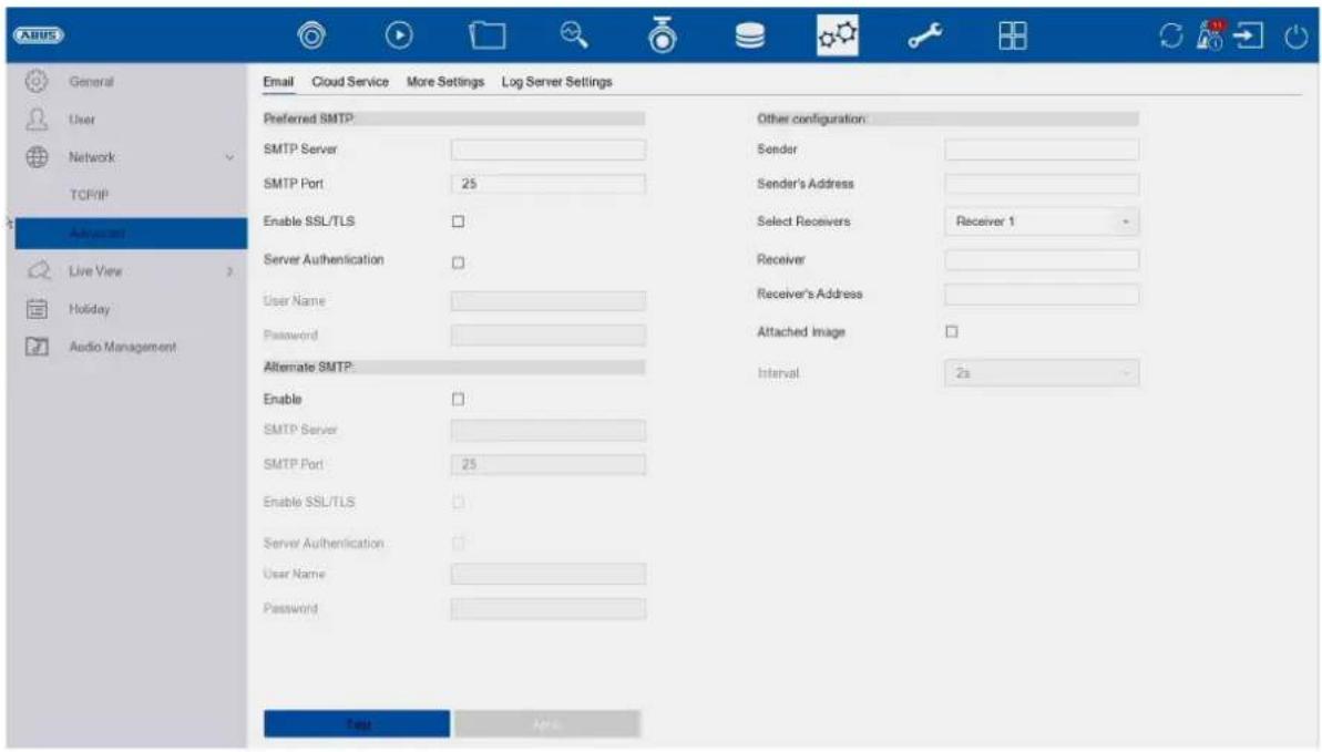
text_image
ABUS General User Network: TCP/IP Advanced Live View > Holiday Audio Management Email Cloud Service More Settings Log Server Settings Preferred SMTP SMTP Server SMTP Port 25 Enable SSL/TLS Server Authentication User Name Password Alternate SMTP: Enable SMTP Server SMTP Port 25 Enable SSL/TLS Server Authentication User Name Password Other configuration: Sender Sender's Address Select Receivers Receiver 1 Receiver Receiver's Address Attached Image Interval 2s Last NextIn the event of an alarm, the device can send a message by e-mail. Enter the e-mail configuration here.
| Server authentication | Activate checkbox if authentication on the server is required/necessary |
| User name Enter the password Enter the sender's name here | user name of your e-mail account here |
| password from your e-mail account here | |
| Sender Enter the sender's name here | |
| Sender address Enter the e-mail address associated with the e-mail account here | |
| Select recipient Here | you can select up to 3 different recipients and then enter their e-mail addresses |
| Receiver Enter the name of the recipient here | |
| Recipient address Enter the e-mail address of the recipient here | |
| Attach picture Activate the checkbox if camera images are to be sent as photo files in addition to the e-mail | |
| Interval Select a trigger time between 2 and 5 seconds here. The images are only sent when motion has been detected over the defined period. | |
| SMTP server Enter the SMTP server address of the e-mail provider here | |
| SMTP Port Enter the SMTP port of the e-mail provider here | |
| Activate SSL/TLS | Activate 'Checkbox' to enable email encryption |
Advanced settings - ABUS Link Station
text_image
ABUS General User Network TCP/IP Advanced Live View Holiday Audio Management Email Cloud Service More Settings Log Server Settings Access Type AUS Link Strates Enable Stream Encryption Verification Code/Encryptio... Registration Status Offline Account Status Unlinked UnbindThe ABUS Link Station service allows simple and uncomplicated remote access, e.g. via a mobile device (without port forwarding).
Note: An internet connection is mandatory to use this service.
| Activate Activate the | checkbox to be able to use the service. |
| After activation, a menu appears to enter the "Verification code" for the first time and agree to the terms of use of the service. | |
| Stream encryption You can activate the encr yption of data transmission here. | |
| Verification code You | can define the verification code here. This is requested by Remote when the connection is established to prevent access by unauthorised third parties. (If stream encryption is activated) |
| Status Shows whether the recorder is connected to the ABUS Link Station service | |
| ABUS Link Station account status | Shows whether the recorder is connected to an ABUS Link Station user account |
In the "ABUS Link Station" app, you can easily add devices by scanning the QR code of the device. You will find this QR code in the scope of delivery or you can use the QR code displayed here in the menu.
Advanced settings- Additional settings

text_image
ABUS General User Network TCP/IP Advanced Live View Holiday Audio Management Email Cloud Service More Settings Log Server Settings Alarm Host IP Alarm Host Port 0 Server Port 8000 HTTP Port 80 Multicast IP RTSP Port 554 IoT Monitoring Port 30999 Enhanced SDK Ser... 8443 Alerts| Alarm Host IP | Network address of the CMS station |
| Alarm Host Port Port of your CMS station (default: 7200) | |
| Server Port Port for data communication to ABUS CMS and iDVR App /ABUS LINK STATION APP (normal connection via IP)(default: 8000) | |
| HTTP port Port of the web server (default: 80) | |
| Multicast IP | You can also enter the multicast IP here to minimise traffic.The IP address must match the one in the video surveillance software. |
| RTSP port Specify the RTSP port(default: 554) | |
| Extended SDKservice connection | (Standard:8443) |
Live view
In the Live view menu, you define the behaviour of the local image output on the recorder.
text_image
ARIS General User Networks Live View General View All-in-and-Stream Holiday Audio Management Video Output Interface 100% Live View Mode 1 * 1 Dwell Time No Switch Enable Audio Output Volume 1 5 3 Event Output HDMI Full Screen Monitoring Dwell Time 10s ApplyGeneral
| Video output Here you can select the connection on which the settings are to be changed | |
| Layout live view mode | You can select the camera layout here:1x1, 2x2, 1+5, 1+7, 3x3, etc. |
| Dwell time Here you can select the switching time between the individual cameras for sequence display | |
| Deactivate audio Activates the audio output for the live view. | |
| VGA: if this option is selected, the audio is output via the cinch sockets on the rear of the recorder | |
| HDMI: if this option is selected, the audio is output via the HDMI interface | |
| Volume You can ad | just the volume here |
| Show event Here | you can define the monitor for the output of events |
| Full screen monitoring Dwell time | Here you can define how many seconds the event should be displayed on the assigned monitor |
Important note: Please do not assign any camera channels to unused monitor outputs, as this will utilise resources from the device without displaying them.
Layout / Adverts
text_image
ARUS General User Network Live View General View All-USB Wireless History Audio Managers Video Output Interface HDM Camera No Camera Name 01 ARUS IP Camera 02 ARUS IP Camera 01 Apply More SettingsHere you can define the camera layout for the selected monitor.
Note: Be aware of possible limitations in the live view with regard to the local decoder performance of the recorder.
Important note: Please do not assign any camera channels to unused monitor outputs, as this uses resources unnecessarily.
Decoding performance & network bandwidth
In the following table you can see the maximum local decoding performance in megapixels for the HDMI/VGA connections and the input/output bandwidth in Mbit/s of the NVR series.
| Decoding performance (MPx)HDMI/VGA port on the device with activated AI | Decoding performance (MPx)HDMI/VGA port on the device with disabled AI | Max. incoming bandwidth in Mbit/s | Max. outgoing bandwidth in Mbit/s | Number of remote connections via LAN IP access | |
| NVR10011 | 40 MPx 64 MPx | 80 Mbps 256 | Mbps 128 | ||
| NVR10021 | 40 MPx 64 MPx | 80 Mbps 256 | Mbps 128 | ||
| NVR10021P | 40 MPx 64 MPx | 80 Mbps 256 | Mbps 128 | ||
| NVR10031 | 40 MPx 64 MPx | 160 Mbps 256 | Mbps 128 | ||
| NVR10031P | 40 MPx 64 MPx | 160 Mbps 256 | Mbps 128 | ||
| NVR10041 | 40 MPx 64 MPx | 320 Mbps 256 | Mbps 128 | ||
| NVR10051 | 40 MPx 64 MPx | 384 Mbps 256 | Mbps 128 |
All-in-One Stream
text_image
A BUS General User Network Live View General View All in one stream Holiday Audio Management Enable All-in-one-Stream Encod Frame Rate Full Frame Max. Bitrate Mode General Max. Bitrate(Kbps) 1792 ApplyYou can activate the "All-in-One" stream here. The recorder then provides an additional stream. The current image of the VGA monitor is transmitted as a combined "image/stream" (camera selection in the stream is no longer possible). This option is helpful if an overview of all cameras is required but only a small bandwidth is available for transmission.
Attention:
As soon as the menu is opened on the VGA monitor, only a black image is transmitted.
Holidays
text_image
ABS General View Network Live View Audio Management No.Holiday Name Status Sat# Date End Date End 1 Holiday1 Disabled 1.Jan 1.Jan 02 2 Holiday2 Disabled 1.Jan 1.Jan 03 3 Holiday3 Disabled 1.Jan 1.Jan 04 4 Holiday4 Disabled 1.Jan 1.Jan 05 5 Holiday5 Disabled 1.Jan 1.Jan 06 6 Holiday6 Disabled 1.Jan 1.Jan 07 7 Holiday7 Disabled 1.Jan 1.Jan 08 8 Holiday8 Disabled 1.Jan 1.Jan 09 9 Holiday9 Disabled 1.Jan 1.Jan 00 10 Holiday10 Disabled 1.Jan 1.Jan 01 11 Holiday11 Disabled 1.Jan 1.Jan 02 12 Holiday12 Disabled 1.Jan 1.Jan 03 13 Holiday13 Disabled 1.Jan 1.Jan 04 14 Holiday14 Disabled 1.Jan 1.Jan 05 15 Holiday15 Disabled 1.Jan 1.Jan 06 16 Holiday16 Disabled 1.Jan 1.Jan 07 17 Holiday17 Disabled 1.Jan 1.Jan 08 18 Holiday18 Disabled 1.Jan 1.Jan 09 19 Holiday19 Disabled 1.Jan 1.Jan 00 20 Holiday20 Disabled 1.Jan 1.Jan 01 21 Holiday21 Disabled 1.Jan 1.Jan 02The holiday schedule has a higher priority than the normal recording schedule and overrides it when activated.
10) Maintenance
In this menu, you can export and import important status information and configuration data and reset the recorder to factory settings, among other things.
System info
text_image
Systemers Kamera Aufstrukturung Abame Nettoorw Fortepläte Explorations Import / Export Update Standard Nettoorw Forgpflüchenkursatz Systemerung CardioName:NVS13001.ABUS.NVR Model:NVS13001 Sahannmethode:057248001CCRHP15887709W.CVU Finanzanmersion:V1.02 325_Buadi 242319 FR Version:V5.2.0 PCI- Version:V1.1.0 FD Version:V5.2.0 Hardware Version:C.R.K2061_KC291.00 MS2.0 Version:V1.1.0This menu displays various information about the system, cameras, recording, alarm, network and storage media.
Logbook
text_image
System Info Import/Export Upgrade Default Network KDD Operation System Service Time 2024-06-26 00:00:00 2024-09-26 23:59:59 Search Major Type All Minor Type Select All ✓ Alarm Input ✓ Alarm Output ✓ Motion Detection Started ✓ Motion Detection Stopped ✓ Video Tampering Detection Started ✓ Video Tampering Detection Stopped ✓ Square Detection Detection Alarm Started ✓ Square Detection Detection Alarm Stopped ✓ Detusion Detection Alarm Started ✓ Detusion Detection Alarm Stopped ✓ Audio Input Exception Alarm Started ✓ Audio Input Exception Alarm Stopped ✓ Sublinear Change of Sound Intensity Alarm Started ✓ Sudan Change of Sound Intensity Alarm Stopped ✓ Face Capture Alarm Started ✓ Face Capture Alarm Stopped ✓ Defocus Detection Alarm Started ✓ Defocus Detection Alarm StoppedAll interactions and events are recorded in the logbook. Entries can be filtered and displayed here according to specific criteria.
Import / Export

text_image
Device Name: USB Flash Disk 1 File Format: *.iso Refresh New Folder Import Export Total Free Capacity 87.42MB Name Size Type Modify Data Delete Play System Volume Index Folder 05-02-2024 07:41:44 TVV621XXX Folder 09-09-2024 01:08:00 App Folder 12-05-2024 08:55:32Here you can import and export the configuration data from the recorder.
Update
text_image
System Info Log info Import/Export Upgrade Default Networks HCD Operation System Reverse Device Name: USB Flash Disk 1 File Format: *.doc - .mmy2.exe Upgrade File Name File Size Filer Type Cable Date Date Flag System Volume Info.Folder 06-02-2024 07:41:44 TVHK52100X Folder 99-58-2024 11:38:50 App Folder 12-09-2024 08:55:32Here you can update the recorder with the latest firmware.
Reset
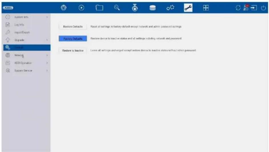
text_image
System Info Log Info Import/Export Upgrade Home IP Networks HCD Operation System Service Restore Defaults Reset all settings to factory default except network and admin password settings Factory Defaults Restore device to inactive status and all settings including network and password Restore to inactive Loise all settings unchanged except restore device to inactive status without admin passwordHere you can reset the settings of the recorder, completely reset the recorder to factory settings or set the recorder back to "inactive".
Network
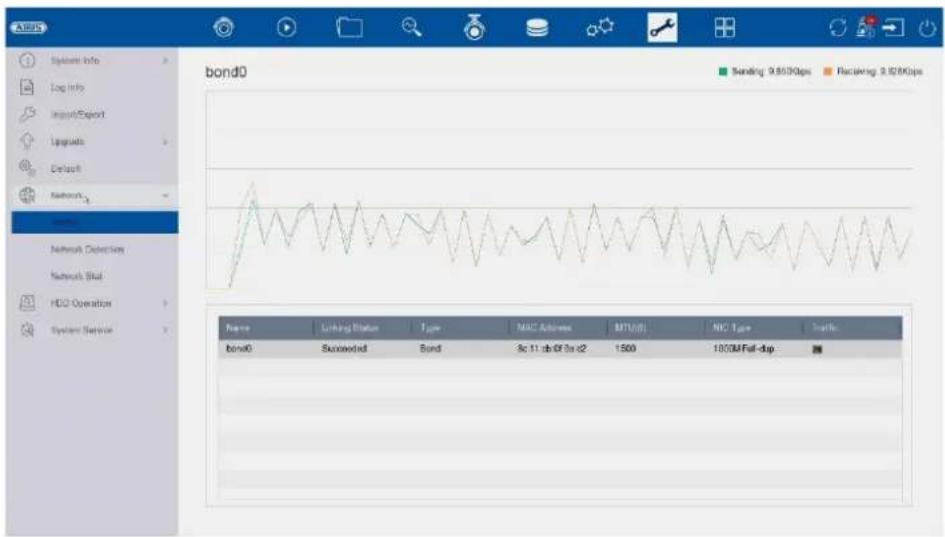
text_image
AERUS System Info Log info Import/Export Updates Default Networks Switch Networks Detection Networks Skal HDD Operation System Service bond0 Sending 9.800Kbps Receiving 9.100Kbps Name Linking Status Type MAC Address MTU(D) NIC Type Traffic bond0 Succeeded Bond 3c 11,ab/0f 3a c2 1500 1000M Full-dapThis menu contains various information on the network interface, network traffic and network status.
Hard disc function
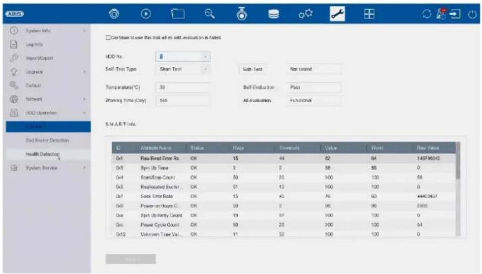
text_image
ADRUS System Info Log Info Input/Object Upgrade Default Network HDD Uptition System Info End Anchor Detection Health Detection System Service Continue to use this disk when self-evaluation is failed HDD No. Self-Test Type Short Test Soft-Test Net Insted Temperature(℃) 38 Self-Evaluation Pass Working Time (Gray) 165 AI-Evaluation Functional S.M.A.R.T Info ID Attribute Name Status Flags Download Value Start Save Value 0x1 Raw Reset Error Ro. OK 15 44 82 64 14976040 0x2 Spin Up Time OK 3 0 88 88 0 0x4 Reset/Step Count OK 50 20 100 100 58 0x5 Reallocated Sector OK 51 10 100 100 0 0x7 Seek Error Rate OK 15 45 76 60 44403457 0x8 Power-on Hours C. OK 50 9 96 96 3988 0x9 Spin Up Entry Count OK 19 97 100 100 0 0x10 Power Cycle Count OK 50 22 100 100 54 0x12 Unknown Tree Val... OK 11 50 100 100 0In this menu you will find various information about the installed hard drive. You can also have the hard drive checked for "Bad Sectors".
System maintenance
Advanced settings
In this menu, you can activate/deactivate various protocol types and switch authentication types (digest/basic).
These settings are already optimised for operation in the factory settings. If the settings are incorrect, operation and access to the NVR may be disrupted.
The "Enable USB Redirect" function is only used for support purposes.
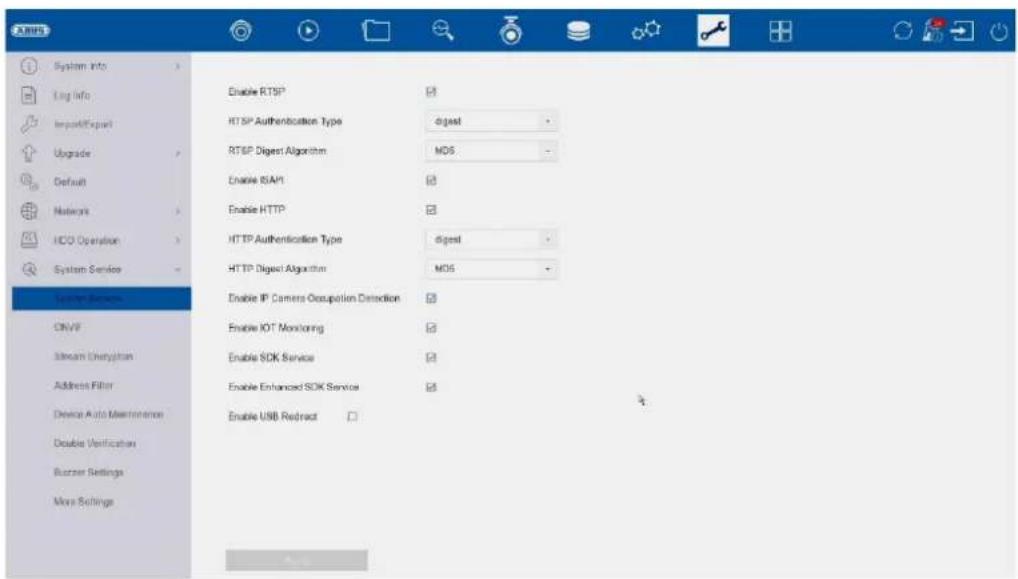
text_image
System Info Log info Impact/Export Upgrade Default Networks HCO Operation System Service System Services ONVP Stream Authentication Address Filter Device Auto Maintenance Double Verification Runner Settings Moss Settings Enable RTSP RTSP Authentication Type digest RTSP Digest Algorithm MD6 Enable ISAM Enable HTTP HTTP Authentication Type digest HTTP Digest Algorithm MD6 Enable IP Camera Occupation Detection Enable IOT Monitoring Enable SDK Service Enable Enhanced SDK Service Enable USB ReductONVIF:
text_image
Oracle OYMF Authentication Type: Upgrade No User Name Security Level Edit Delete User Name Security Level Edit Delete Show Exchange Address Filter Device Auto Maintenance Disable Audio Settings Bumper Settings Move Settings AddHere you can activate the ONVIF function and create users who are authorised to access the NVR via the ONVIF protocol.
Stream encryption:
text_image
Enable EBITAM Encryption Encryption Password The stream encryption key is synchronized with the ASUS Link Station service verification code. After enabling the encryption code, the ASUS Link Station stream will be forcedy encrypted. More sure the ASUS Link Station service supports stream decryption.Here you can activate/deactivate stream encryption for access via the ABUS LINK STATION app and change your verification code. This is required to access the live images in the app and remotely via the web interface and ABUS CMS software.
Address filter:
text_image
Enable Refriction Mode + IP Address - MAC Address Refriction Type Allow - Parfe Refriction List Add Edit Delete No IP Address Device Auto Maintenance Double Verification Stutter Settings Move SettingsAn authorisation filter can be created in this menu. This can "authorise" or "prohibit" IP or MAC addresses. Select the desired type (IP or MAC) and the authorisation type (Allow / Deny) and then click on "Add".
Attention: The filter becomes active immediately when you click "Apply". Make absolutely sure that the correct filter rule is created and that you do not block yourself.
Automatic restart of the recorder
text_image
ABUS System Info Log Info Import/Export Upgrade Default Network HDD Operation System Service System Service ONVIF Stream Encryption Address Filter Drive Active Maintenance Double Verification Buzzer Settings More Settings Enable Schedule Reboot ApplyAn automatic time-controlled restart of the recorder can be configured here.
4-eyes principle:
text_image
ARMOS □Enable Double Verification System Info Log Info Import/Export Upgrade Default Network HOLD Operation System Service System Service CMVIF Stream Engine/ Address Filter Device Auto Maintenance HOLD Operation Suzzer Settings Vbox SettingsThe 4-eyes principle (double check/verification) enables double verification of a "guest" or "operator" user for the following actions:
- Local playback
- Remote playback
- Local video export
One of these actions can then only be carried out if the "4-eyes" user enters his password and thus represents a double verification.
You can create up to 8 different "4-eyes" users.
Setting up the dual control principle using the example of a newly created user with the "Operator" authorisation level:
1) Create a new "Operator" under "System" / "User" and enter the required authorisations (regardless of dual control access)
2) Activate the function under "Maintenance" / "System maintenance" / "Dual control principle" and create a new user who is intended for double verification.
3) In the "4-eyes principle" menu, specify the desired cameras, which can only be accessed via double verification.
Info: The "4-eyes" authorisations can also be edited under "System / User" for the respective user under "Authorisation".
4) Now the "operator" queries the "4-eye" user for the desired cameras during the action.
This procedure is identical for a "guest" user.
Buzzer settings:
The NVR's integrated piezo beep can be completely activated/deactivated here.
Further settings:
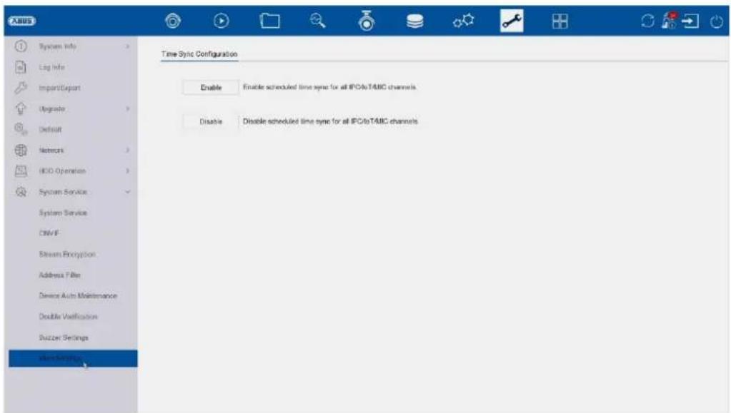
Activate/deactivate time sync:
Determines whether the NVR may also pass on the time to devices such as cameras, door intercom systems, etc.
ABUS NVR100x1(P)
natural_image
Exterior view of a black electronic device labeled 'ARIS' with a circular logo on top (no readable text beyond branding)
natural_image
Front view of a black server rack with ventilation grilles and indicator lights (no visible text or labels)Importation / Exportation 212
Mise à jour 213
Remise à zéro 213
Réseau....214
Directive RoHS 2011/65/EU
text_image
Activation admin Create New Password Conform New Password Export GUID Create Channel Default Password Note Valid password range [8-16]. You can use a combination of numbers, lowercase, uppercase and special character for your password with at least two kinds of them contained. OKtext_image
Resetting Password ① Please configure at least one password resetting method. Email ABUS Link Stati... Security Question Reserved E-mail Apply Closing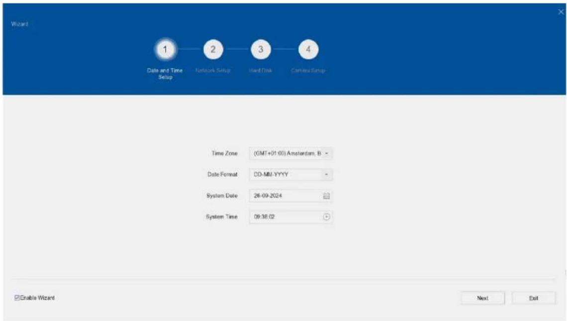
text_image
Wizard 1 Date and Time Setup 2 Network Setup 3 Hand Disk 4 Camera Setup Time Zone (GMT+01:00) Amsterdam, B - Date Format DD-MU-YYYY - System Date 26-09-2024 System Time 09:36:02 Enable Wizard Next Exittext_image
ABUS Channel Target [D1] ABUS IP Camera [D2] ABUS IP Camera 26-09-2024 08:43:34 ABUS IP Cameratext_image
2019-12-18 14:08:01text_image
Face Picture Library List Add Delete Clear in... Import Export No Name Total Pictures Normal Pictures Abnormal Pictures Edit Del 1 about1924 1 1 0text_image
Smart Search Face Picture Library Smart Event Settings Face Capture Face Picture C... Enable Face Capture Sensitivity 1 5 3 Aming Schedule Linkage Action Continuous None Edit Mon 1 Tue 2 Wed 3 Thu 4 Fri 5 Sat 6 Sun 7 0 2 4 6 8 10 12 14 16 18 20 22 24 Apply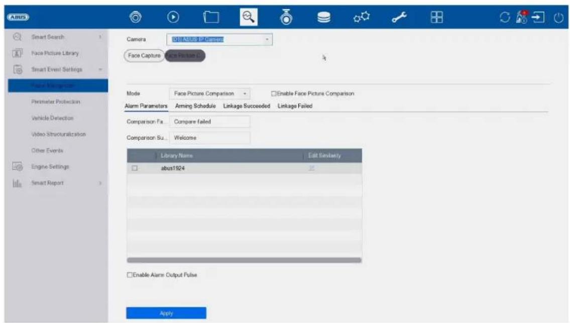
text_image
ABUS Smart Search Face Picture Library Smart Event Settings Face Navigation Primerizer Protection Vehicle Detection Video Structuralization Other Events Engine Settings Smart Report Camera BST ABUS IN Camera Face Capture Voice Picture C Mode Face Picture Comparison Enable Face Picture Comparison Alarm Parameters Arming Schedule Linkage Succeeded Linkage Failed Comparison Fa... Compare failed Comparison Su... Welcome Library Name Edit Instanty abus1924 Enable Alarm: Output Pulse Applytext_image
ANUS Smart Search Face Picture Library Smart Event Settings Facial Recognition Appearance (Standard) Vehicle Detection Video Structuralization Other Events Engine Settings Smart Report Camera D:\1\ABUS IP Camera Enable AI by NVR Camera Drive Infusion Region Entrance Region Exiting Enable Tripwire Detection Detection Area Settings Arming Schedule Linkage Action Arming Area 1 Direction A<>B Sensitivity 1 100 50 Detect: Human Vehicle Detection Ar Draw Area Clear All Size Filter Max. Size Min. Size OKtext_image
Add IP Camera (Custom) No | Sta... | Security | IP Address | Device Model 1 - ✓ Active 192.168.0.244 IPCB64510B 2 ✓ Active 192.168.0.31 IPCB78521 3 ✓ Active 192.168.0.13 IPCB64521 IP Camera Address 192.168.0.244 Protocol ABUS Management Port 45003 Transfer Protocol Auto User Name installer Password Use Channel Default... Enable IP Camera T... Use Default Port ✓ Verify Certificate Search Continue to Add Addtext_image
Pse Power Configuration Pse Bonding Configuration Actual power: 10.7W. Remaining power: 109.3W. Channel Long Distance Short Distance Channel Status Actual Power D1 * Disconnected 0.0W D2 * Connected 3.0W D3 * Disconnected 0.0W D4 * Connected 4.7W D5 * Disconnected 0.0W D6 * Disconnected 0.0W D7 * Connected 3.0W D8 * Disconnected 0.0Wtext_image
UBUS Camera ID:ABUS IP Camera Camera Name: ABUS IP Camera IDB Settings Display Name Display Date Date Format: CD-MM-YYYY Time Format: 24 Hour Display Mode: Non-Transparent & Not Floating Image Settings > Exposure > Day/Night Switch > Backlight > Image Enhancement >text_image
A BUS Camera Display Primary Name Video Parameters Export Camera D:\ A BUS IP Camera Kinase Clear Area 1 Clear Area 2 Clear Area 3 Clear Area 4 Clear All Applytext_image
ABUS Camera Display Privacy Mesh Video Parameters Main Stream SubStream Event Camera [D:\JABUB IP Camera Encoding Parameters Main Stream(Continuous) Main Stream(Event) Stream Type Video Video Resolution 3840*2160(BMP) 3840*2160(BMP) Bitrate Type Variable Variable Video Quality Medium Medium Frame Rate Full Frame Full Frame Max. Bitrate Mode Custom(32-16384) Custom(32-16384) Max. Bitrate(Kbps) 12258 12258 Max. Bitrate Range Recom... 15246-16384(Kbps) 15246-16384(Kbps) Video Encoding N 264 N 264 iFrame Interval 60 S2 Enable N 264+ Note: Different frame rate of continuous and event recording may cause problems in the exported AVI video. Add Deletetext_image
Camera Display Privacy Mask Video Parameters Event Monitor Base Motion Detection Video Tampering Video Loss Alarm Input Alarm Output Exception Camera 10:15 TABLE @ Camera Enable AI by N/R Enable Area Aiming Schedule Linkage Action Sensitivity 0 100 60 Detects Human Vehicle Draw Area Clear Applytext_image
Airbus Camera Display Privacy Mask Video Parameters Event Normal Event Motion Detection Video Tampering Video Loss Alarm Input Alarm Output Exception Camera D:\TAEUS IF Camera Enable AI by NVR Enable Area Arming Schedule Linkage Action Sensitivity 0 100 60 Detecti... Human Vehicle Draw Area Clear Applytext_image
A8US Schedule Capture Audio Record Storage Device SSU Management Storage Mode Auto Backup Advanced Camera No: [O1] A8US P Cameras Enable Schedule Advanced Continuous Event Motion Det Alarm M/A M&A None Edit 0 2 4 6 8 10 12 14 16 18 20 22 24 Non Tue Wed Thu Fri Sat Sun 1 2 3 4 5 6 7 Top... Playboxtext_image
ASUS Schedule Record Camera No: [D:\] ASUS. IP Camera Enable Schedule Advanced Continuous Event Motion Dist... Alarm M | A M & A None Edit Mon 1 Tue 2 Wed 3 Thu 4 Fri 5 Sat 6 Sun 7 *Note: Operation is invalid when the number of time segments exceeds the limit (5): Apply Createtext_image
AABB Schedule Add Edit Repair Database Total Capacity 14.06TB Free Space 14.19TB Label Cancelty Status Property Time Free Space Group Edit Delete 1 14.50TB National R/W Local 14.19TB 1 -text_image
Abi95 Schedule Storage Device ISO Management Storage Mode Auto Backup Advanced Space distribution: 1.40GB of 7.25GB available. Formal 5.78GB 98MB 1.40GB System Reserved Face Picture Library Free Initialize Face Picture ...Mode de stockage
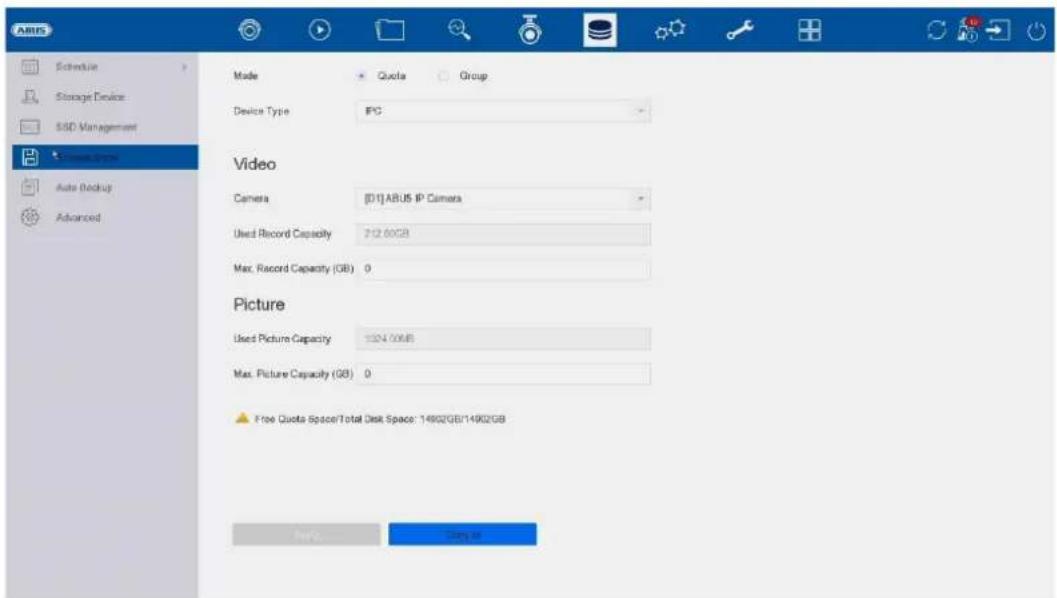
text_image
ARIS Schedule Storage Device SSD Management Video Type Auto Backup Advanced Mode Quote Group Device Type IPC Video Camera [01]ABUS IP Camera Used Record Capacity 742.00GB Max. Record Capacity (GB) 0 Picture Used Picture Capacity 1324.00GB Max. Picture Capacity (GB) 0 Free Quota Space/Total Disk Space: 14902GB/14902GB Play... Canceltext_image
A BUS Schedule Storage Device SSC Management Upgrade Mode Auto Backup Advanced Backup Status Current Status Unplanned Last Backup Unplanned Auto Backup Settings... Auto Backup Start Backup at 00:00 Select Channel(s) for B... Select All □08 □02 □03 □04 □06 Backup Stream Type Main Stream Sub-Stream Dual Stream Backup to USB Select Device Overwrite Enable Logtext_image
Language English Time Zone (GMT+01:00) Amsterdam, B Date Format DD-MM-YYYY System Date 26-09-2024 System Time 10:02:37 Device Name NVR10011 ABUS NVR Device No. 255 Auto Log out 5 Minutes Menu Output Mode Auto Enable Wizard Enable Password VGA Resolution 1920*1080/60HZ(1080P) HDMI Resolution 1920*1080/60HZ(1080P) Mouse Pointer Speed Slow Fast CVBS Output Brightness Low High Output Standard PAL Enable DST Start Time Mar Last Sun 2 8 00 End Time Oct Last Sun 3 8 00 DST Bias 60 Minutes Nonetext_image
ABUS General Network Live View Holiday Audio Management Add Modify Delete Live View Per... No User Name Security Priority User's MAC Address Permission 1 admin Weak Password Admin 00:00:00:00:00 admintext_image
Edit User User Name admin Password Modify User's MAC Ad... 00 00 00 00 00 00 Unlock Pattern Enable Unlock Pattern Reserved F-mail 1****@lotte Modify GUD File Export Security Quest... OK Cancel User's MAC Address Permission 1 admin 00:00:00:00:00:00text_image
ABUS General User Network: TCP/IP Alternate Live View Holiday Audio Management Email Cloud Service More Settings Log Server Settings Preferred SMTP SMTP Server SMTP Port 25 Enable SSL/TLS Server Authentication User Name Password Alternate SMTP: Enable SMTP Server SMTP Port 25 Enable SSL/TLS Server Authentication User Name Password Test Add Other configuration: Sender Sender's Address Select Receivers Receiver 1 Receiver Receiver's Address Attached Image Interval 2stext_image
IBM General User Network TCP/IP Access Live View Holiday Audio Management Email Cloud Service More Settings Log Server Settings Access Type ASUS Link Status Enable Stream Encryption Verification Code/Encryption... Registration Status Offline Account Status Unlinked Unbindtext_image
ARUG General User Networks Live View General View All-in-one-Stream Holiday Audio Management Video Output Interface HDMI Event Output HDMI Live View Mode 1 * 1 Full Screen Monitoring Dwell Time 10s Dwell Time No Switch Enable Audio Output Volume 1 5 3 ApplyGénéral
text_image
ADUS General User Network Live View General View All-in-one-Stream Holiday Audio Management Video Output Interface HDM Camera No Camera Name D1 ABUS IP Camera D2 ADUS IP Camera D1 Apply More Settingstext_image
ABUS General User Network Live View General View All in-one-Stream Encod Holiday Audio Management Enable All-in-one-Stream Encod Frame Rate Full Frame Max. Bitrate Mode General Max. Bitrate(Kbps) 1792 Applytext_image
Alaris System Info Type 2024-08-29 00:00:00 2024-08-29 23:59:59 Search Major Type All Minor Type Select All ✓ Alarm Input ✓ Alarm Output ✓ Motor Detection Started ✓ Motion Detection Stopped ✓ VideoTampering Detection Started ✓ VideoTampering Detection Stopped ✓ Temporary Detection Detection Alarm Started ✓ Temporary Detection Detection Alarm Stopped ✓ Deflection Detection Alarm Started ✓ Inflection Detection Alarm Stopped ✓ Audio Input Exception Alarm Started ✓ Audio Input Exception Alarm Stopped ✓ Sublinear Change of Sound Intensity Alarm Started ✓ Sustained Change of Sound Intensity Alarm Stopped ✓ Face Capture Alarm Started ✓ Face Capture Alarm Stopped ✓ Defocus Detection Alarm Started ✓ Defocus Detection Alarm StoppedImportation / Exportation
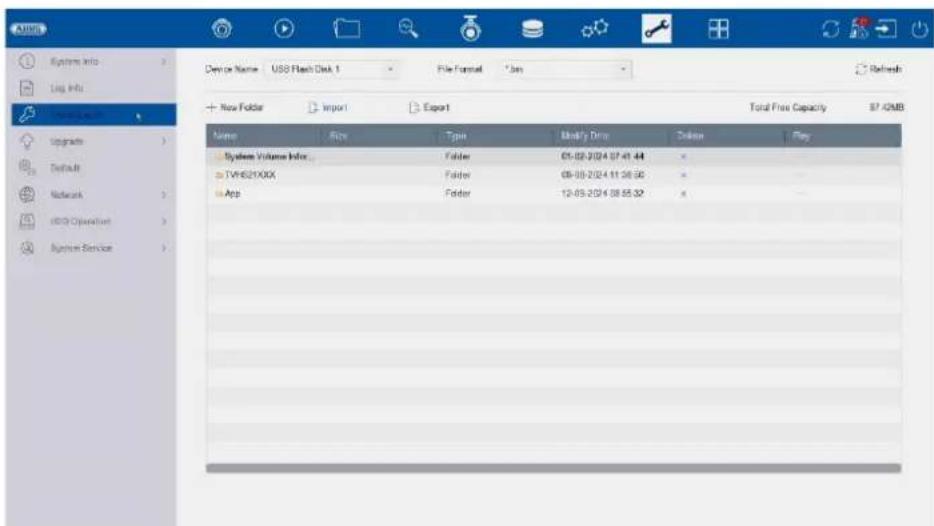
text_image
System Info Log Info Device Name: USB Flash Disk 1 File Format: *.box Refresh + New Folder Import Export Total Free Capacity $7.42MB Name Size Type Modify Drop Delete Play System Volume Index Folder 05-08-2024 07:41:44 TVHS21XXX Folder 08-08-2024 11:36:58 App Folder 12-05-2024 08:55:52text_image
System info Log info Import/Export Upgrade System Networks HCD Operation System Service Bottom Defaults Place all settings to factory default except network and admin password and settings Factory Defaults Place the device to inactive status and all settings including network and password Place to inactive I have all settings unchanged except restore device to inactive status without admin passwordtext_image
Bond0 Sending: 9.852Kops Receiving: 9.828Kops Name Linking Status Type MAC Address MTU10 NPC Type Traffic bond0 Suspended Bond 6c 11 db OR 6c 2 1500 1000M Full-uptext_image
System Info Log MMs Import/Export Upgrade Default Network HOD Operation End Sector Detection Health Detection System Service Continue to use this disk when self-evaluation is failed. HOD No. Self-Test Type Short Test Self-Test Not Insted Temperature(℃) 39 Self-Evaluation Pass Working Time (Day) 165 All-Evaluation Functional S.M.A.R.T info ID Attribute Name Status Pages Download Value Values Raw Value 0x1 Raw Read Error Rs. OK 15 44 82 64 14976040 0x3 Spin Up Time OK 3 0 88 88 0 0x4 StartStop Count OK 50 20 100 100 58 0x5 Reallocated Sector OK 51 12 100 100 0 0x7 Seek Error Rate OK 15 45 76 60 44409437 0x9 Power-on Hours C OK 50 0 90 96 3966 0x6 Spin Up Retire Count OK 19 97 100 100 0 0x9 Power Cycle Count OK 50 20 100 100 54 0x12 Unknown Type Val OK 11 55 100 100 0text_image
A BUS System Info Log info Import/Export Upgrade Default Network HDD Operation System Service ONVP Stream Encryption Address Filter Device Auto Maintenance Disable Verification Buzzer Settings More Settings Enable RTSP RTSP Authentication Type digest RTSP Digest Algorithm MD6 Enable ISAPI Enable HTTP HTTP Authentication Type digest HTTP Digest Algorithm MD6 Enable IP Camera Occupation Detection Enable IOT Monitoring Enable SDK Service Enable Enhanced SDK Service Enable USB Redirect AddONVIF :

text_image
CREATE Systems Info Log Info Import/Export Update Default Network HDD Operation Systems Service Systems Service Delete SimSun Designation Address Floor Device Auto Maintenance Disable Verification Button Settings Move Settings Delete OTVIF Authentication Type: Signal No Access Name Security Load Edit Deletetext_image
Athens Encrypted Stream Encryption Encryption Password The stream encryption key is synchronized with the AUSI Link Station service verification code. After enabling the encryption code, the AUSI Link Station stream will be forcedly encrypted. Make sure the AUSI Link Station service supports stream decryption. Address https Device Auto Maintenance Disable Verification Buzzer Settings Menu Settings Applytext_image
System Info Log Info Import Export Upgrade Default Network HDD Operation System Vendor System Service DRHP Browse Encryption User(s) Device Auto Maintenance Double Verification Buffer Settings More Settings Enable Restriction Mode IP Address MAC Address Restriction Type Allow Failed Restriction List +Add Edit Online No IP Address OK Canceltext_image
ABUS System Info Log Info Import/Export Upgrade Default Network HDD Operation System Service System Service ONVIF Stream Encryption Address Filter Device Auto Maintenance Double Verification Buzzer Settings More Settings Enable Schedule Reboottext_image
ARMOS □Enable Double Verification □System Info Log Info Import/Export Upgrade Default Network HOLD Operation System Service System Service ONVIF Stressen Encryption Address Filter Device Auto Maintenance Double Version Soccer Settings More Settingstext_image
System Info Log Info Import/Export Upgrade Default Network HDD Operation System Service System Service ONVP Stream Encryption Address File Device Auto Maintenance Double Verification Target Building More Settings Enable Buttontext_image
ANSYS System Info Log Info ImportExport Upgrade Default Network HDD Operation System Service System Service ONVIF Stream Encryption Address Filter Device Auto Maintenance Double Verification Buzzer Settings Main Settings Time Sync Configuration Enable Enable scheduled time sync for all IPC/loTAMC channels Disable Disable scheduled time sync for all IPC/loTAMC channelsnatural_image
Exterior view of a black electronic device labeled 'AETIS' with no visible text or symbols on its body.
natural_image
Front view of a black desktop computer tower with ventilation grille and drive buttons (no visible text or labels)text_image
Activation admin Create New Password Confirm New Password Export GUID Create Channel Default Password Note Valid password range [0-16]. You can use a combination of numbers, licenses, up Exercise and special character for your password with at least two kinds of them contained. OKtext_image
Resetting Password ① Please configure at least one password resetting method. Email ABUS Link Stati... Security Question Reserved E-mail Apply Construct
text_image
Wizard 1 Date and Time Setup 2 Network Setup 3 Hand Disk 4 Camera Setup Time Zone (GMT+01:00) Amsterdam, B - Date Format DD-MU-YYYY - System Date 26-09-2024 System Time 09:36:02 Enable Wizard Next Exittext_image
Abus Channel Target [D1] ABUS IP Camera [D2] ABUS IP Camera 26-09-2024 08:43:34 Abus IP Cameratext_image
2019-12-16 14:08:01text_image
Smart Search Face Picture Library Smart Event Settings Face Capture Face Picture C Enable Face Capture Sensitivity 1 5 3 Arming Schedule Linkage Action Continuous None Edit Mon 1 Tue 2 Wed 3 Thu 4 Fri 5 Sat 6 Sun 7 0 2 4 6 8 10 12 14 16 18 20 22 Apply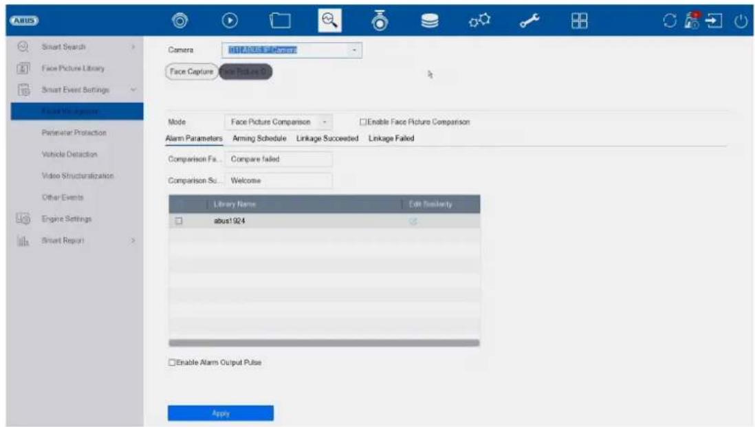
text_image
ABUS Smart Search Face Picture Library Smart Event Settings Voice Management Perimeter Protection Vehicle Detection Video Structuralization Other Events Engine Settings Smart Report Camera Face Capture Face Picture Comparison Mode Face Picture Comparison Enable Face Picture Comparison Alarm Parameters Arming Schedule Linkage Succeeded Linkage Failed Comparison Fa... Compare failed Comparison Su... Welcome Library Name Edit Similarity abus1924 Enable Alarm Output Pulse Applytext_image
ABUS Smart Search Face Picture Library Smart Event Settings Facial Recognition Sensor/Pharmdata Vehicle Detection Video Structuralization Other Events Engine Settings Smart Report Camers [D:\I\ABUS IP Camera] Enable AI by NVR Intrusion Region Entrance Region Exiting Enable Triceps Detection Detection Area Settings Arming Schedule Linkage Action Arming Area 1 Direction A<>S Sensitivity 1 100 50 Detect... Human Vehicle Detection Ar. Draw Area Clear All Size Filter Max. Size Min. Size Rtext_image
Add IP Camera (Custom) No | Sta... | Security | IP Address | Device Model 1 - ✓ Active 192.168.0.244 IPCB64510B 2 ✓ Active 192.168.0.31 IPCB78521 3 ✓ Active 192.168.0.13 IPCB64521 IP Camera Address 192.168.0.244 Protocol ABUS Management Port 45003 Transfer Protocol Auto User Name installer Password Use Channel Default... Enable IP Camera T... Use Default Port ✓ Verify Certificate Search Continue to Add Addtext_image
PdE Power Configuration PdE Bonding Configuration Actual power: 10.7W. Remaining power: 109.3W Channel Long Distance Short Distance Channel Status Actual Power D1 ○ ● Disconnected 0.0W D2 ○ ● Disconnected 3.0W D3 ○ ● Disconnected 0.0W D4 ○ ● Disconnected 4.7W D5 ○ ● Disconnected 0.0W D6 ○ ● Disconnected 0.0W D7 ○ ● Disconnected 3.0W D8 ○ ● Disconnected 0.0Wtext_image
ANSYS Camera D:\LABUS\IP Camera Encoding Parameters Stream Type Resolution Bitrate Type Video Quality Frame Rate Max. Bitrate Mode Max. Bitrate(Kbps) Max. Bitrate Range Recom... Video Encoding I Frame Interval Enable H 264+ Main Stream(Continuous) Video 3840*2100(BMP) Variable Medium Full Frame Custom(32-16384) 12258 15246-16384(Kbps) H 264 50 Main Stream(Event) Video 2940*2100(BMP) Variable Medium Full Frame Custom(32-16384) 12258 15246-16384(Kbps) H 264 50 Note: Different frame rate of continuous and event recording may cause problems in the exported AVI video. MIP CPIPtext_image
ANSYS Camera Display Privacy Mask Video Parameters Event Motion Detection Video Tampering Video Loss Alarm Input Alarm Output Exception Camera USB ARSLS IP Camera Enable AI by NVR Enable Area Among Schedule Linkage Action Sensitivity 0 100 60 Detects Human Vehicle Draw Area Clear Applytext_image
ABUS Camera Display Privacy Mask Video Parameters Event Motion Detection Video Tampering Video Loss Alarm Input Alarm Output Exception Camera DO ABCSTI Camera Enable AI by NVR Enable Area Arming Schedule Linkage Action Sensitivity 0 100 60 Detecti... Human Vehicle Draw Area Clear Applytext_image
ASUS Schedule Capture Audio Record Storage Device SSU Management Storage Mode Auto Backup Advanced Camera No. [D:\]ASUS IP Camera Double Schedule Advanced Continuous Event Motion Det Alarm M/A M&A None Edit Non 1 Tue 2 Wed 3 Thu 4 Fri 5 Sat 6 Sun 7 0 2 4 6 8 10 12 14 16 18 20 22 24 Menu Canceltext_image
Schedule Record Camera Audio Record Storage Device BSD Management Storage Mode Auto Backup Advanced Camera No. [D1] ABUS IP Camera Enable Schedule Advanced Continuous Event Motion Det Alarm M | A M & A None Edit Mon 1 Tue 2 Wed 3 Thu 4 Fri 5 Sat 6 Sun 7 0 2 4 6 8 10 12 14 16 18 20 22 24 *Note: Operation is invalid when the number of time segments exceeds the limit (S). Apply Createtext_image
AABB Schedule Add Edit Repair Database Total Capacity 14.30TB Free Space 14.19TB Label Capacity Status Properties Type Free Space Group Edit Delete SMD Management Storage Mode Auto Dockup Advanced 14.56TB Normal R292 Local 14.19TB 1 -text_image
Abi95 Schedule Storage Device ISO Management Storage Mode Auto Backup Advanced Space distribution: 1.40GB of 7.25GB available. Formal 5.78GB 98MB 1.40GB System Reserved Face Picture Library Free Initialize Face Picture ...Opslagmodus

text_image
Schedule Storage Device SSD Management * Storage System Auto Backup Advanced Mode Quota Group Device Type IPC Video Camera [01]ABUS IP Camera Used Record Capacity P12.60GB Max. Record Capacity (GB) 0 Picture Used Picture Capacity 1324.00MB Max. Picture Capacity (GB) 0 Free Quote Space/Total Disk Space: 14902GB/14902GB Apply Canceltext_image
A BUS Schedule Storage Device R&D Management Storage Mode Auto Backup Advanced Backup Status Current Status Unplanned Last Backup Unplanned Auto Backup Settings... Auto Backup Start Backup at 00:00 Select Channel(s) for B... □ Select All □01 □02 □03 □04 □05 Backup Stream Type Main Stream Sub-Stream Dual Stream Backup to USB Select Device Overwrite Enable Enabletext_image
ABUS General Network Live View Holiday Audio Management Add Modify Delete Live View Per... No User Name Security Priority User's MAC Address Permission 1 admin Weak Password Admin 00:00:00:00:00 admintext_image
Edit User User Name admin Password Modify User's MAC Ad... 00 : 00 00 : 00 : 00 : 00 Unlock Pattern Enable Unlock Pattern Reserved E-mail t****@lot.ie Modify GUID File Export ? Security Questi... OK Cancel User's MAC Address Permission 1 admin 00:00:00:00:00:00text_image
ABUS General User Network: TCP/IP Access Live View Holiday Audio Management Email Cloud Service More Settings Log Server Settings Preferred SMTP SMTP Server SMTP Port 25 Enable SSL/TLS □ Server Authentication □ User Name Password Alternate SMTP: Enable □ SMTP Server SMTP Port 25 Enable SSL/TLS □ Server Authentication □ User Name Password Other configuration: Sender Sender's Address Select Receivers Receiver 1 Receiver Receiver's Address Attached Image □ Interval 2s Capt. Applytext_image
ABUS General User Network: TCP/IP Access Type AUS Link Status Enable Stream Encryption Verification Code/Encryption... Registration Status Offline Account Status Unlinked Unbind Live View Holiday Audio Managementtext_image
ARIS General User Networks Live View General View All-in-and-Stream Holiday Audio Management Video Output Interface 100% Live View Mode 1 * 1 Dwell Time No Switch Enable Audio Output Volume 1 5 3 Event Output HDMI Full Screen Monitoring Dwell Time 10s ApplyAlgemeen
Lay-out / Advertenties
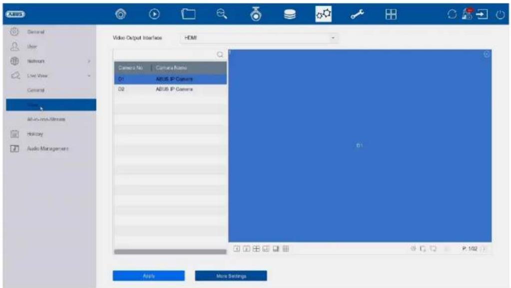
text_image
ARUS General User Network Live View General Video Output Interface HDMI Camera No Camera Name 01 ARUS IP Camera 02 ARUS IP Camera All-USB/Internet History Audio Management Apply More Settingstext_image
ABUS General User Network Live View General View All-in-one-Stream Holiday Audio Management Enable All-in-one-Stream Encod... Frame Rate Full Frame Max Bitrate Mode General Max Bitrate(Kbps) 1792 Applytext_image
System info Type: 2024-08-26 00:00:00 2024-08-26 23:39:58 Major Type All Minor Type Select All Alarm Input Alarm Output Motor Detection Started Motor Detection Stopped Video Tampering Detection Started Video Tampering Detection Stopped Tigrain Detection Detection Alarm Started Tigrain Detection Detection Alarm Stopped Detusion Detection Alarm Started Detusion Detection Alarm Stopped Audio Input Exception Alarm Started Audio Input Exception Alarm Stopped Sound Change of Sound Intensity Alarm Started Sound Change of Sound Intensity Alarm Stopped Face Capture Alarm Started Face Capture Alarm Stopped Defocus Detection Alarm Started Defocus Detection Alarm StoppedImporteren/exporteren
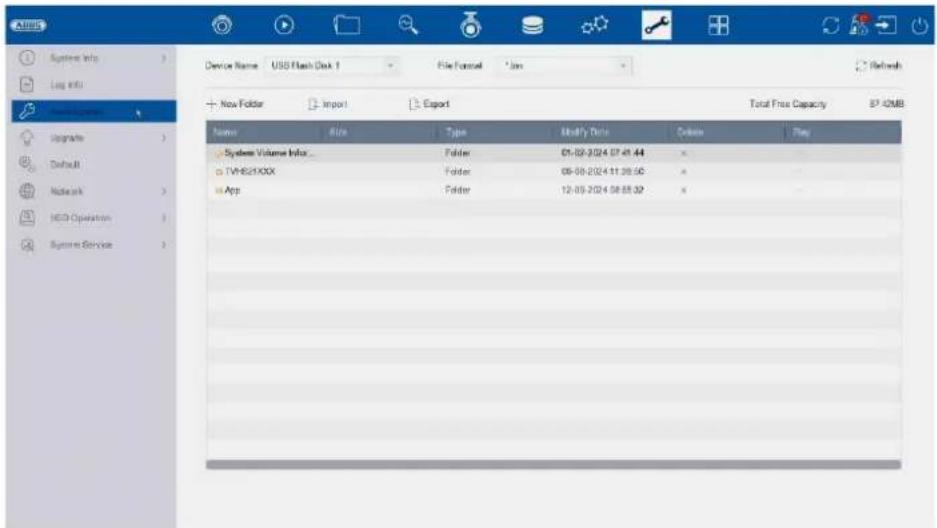
text_image
System Help Log info Device Name: USS Flash Disk 1 File Format: *.jns + New Folder Import Export Total Free Capacity SP 42MB Name Size Type Modify Date Delete Play System Volume Info... Folder 01-02-2024 07-01-44 x TVH821XXX Folder 08-08-2024 11:39:56 x App Folder 12-03-2024 08:55:32 xtext_image
System info Log Info Import/Export Upgrade Network Networks HCD Operation System Service Restore Defaults Reset all settings to factory default except network and admin password settings Factory Defaults Restore device to inactive status and of settings including network and password Restore to inactive Lease all settings unchanged except restore device to inactive status without admin passwordtext_image
Bond0 Sending: 9.852Kops Receiving: 9.828Kops Name Linking Status Type MAC Address MTU10 NPC Type Traffic bond0 Suspended Bond 6c 11 db OR 6c 2 1500 1000M Full-uptext_image
System Info Log MMs Import/Export Upgrade Default Network HOD Operation End Sector Detection Health Detection System Service Continue to use this disk when self-evaluation is failed. HOD No. Self-Test Type Short Test Self-Test Not Insted Temperature(°C) 39 Self-Evaluation Pass Working Time (Day) 165 All-Evaluation Functional S.M.A.R.T info ID Attribute Name Status Pages Download Value Values Raw Value 0x1 Raw Read Error Rs. OK 15 44 82 64 14976040 0x3 Spin Up Time OK 3 0 88 88 0 0x4 StartStop Count OK 50 20 100 100 58 0x5 Reallocated Sector OK 51 12 100 100 0 0x7 Seek Error Rate OK 15 45 76 60 44409437 0x9 Power-on Hours C OK 50 0 90 96 3966 0x6 Spin Up Retire Count OK 19 97 100 100 0 0x9 Power Cycle Count OK 50 20 100 100 54 0x12 Unknown Type Val OK 11 55 100 100 0text_image
ANSYS System info Log info Import/Export Upgrade Default Network HED Operation System Services System Services ONVF Stream Encryption Address Filter Device Auto Maintenance Disable Verification Register Settings Move Settings Enable RTSP RTSP Authentication Type digest RTSP Digest Algorithm MOS Enable ISAP Enable HTTP HTTP Authentication Type digest HTTP Digest Algorithm MOS Enable IP Camera Occupation Detection Enable IOT Monitoring Enable SDK Service Enable Enhanced SDK Service Enable USB Redirect ApplyONVIF:
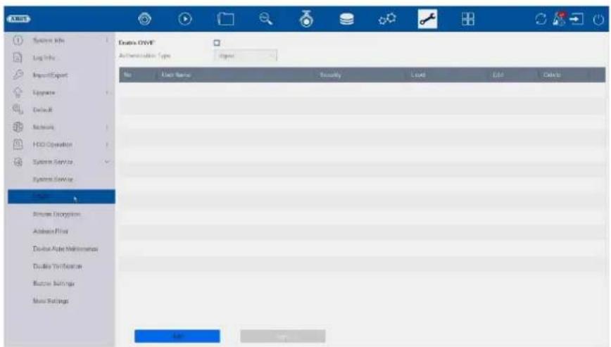
text_image
Double OUTF Authentication Type: Integer No User Name Security Load Edit Delete Double OUTF Double OUTF Double OUTF Double OUTF Double OUTF Double OUTF Double OUTF Double OUTF Double OUTF Double OUTF Double OUTF Double OUTF Double OUTF Double OUTF Double OUTF Double OUTF Double OUTF Double OUTF Double OUTF Double OUTF Double OUTF Double OUTF Double OUTF Double OUTF Double OUTF Double OUIF Double OUIF Double OUIF Double OUIF Double OUIF Double OUIF Double OUIF Double OUIF Double OUIF Double OUIF Double OUIF Double OUIF Double OUIF Double OUIF Double OUIF Double OUIF Double OUIF Double OUIF Double OUIF Double OUIF Double OUIIF Double OUIIF Double OUIIF Double OUIIF Double OUIIF Double OUIIF Double OUIIF Double OUIIF Double OUIIF Double OUIIF Double OUIIF Double OUIIF Double OUIIF Double OUIIF Double OUIIF Double OUIIF Double OUIIF Double OUIIF Double OUIIF Double OUIIF Double OUIIIF Double OUIIIF Double OUIIIF Double OUIIIF Double OUIIIF Double OUIIIF Double OUIIIF Double OUIIIF Double OUIIIF Double OUIIIF Double OUIIIF Double OUIIIF Double OUIIIF Double OUIIIF Double OUIIIF Double OUIIIF Double OUIIIF DoubleOUIIIF DoubleOUIIIF DoubleOUIIIF DoubleOUIIIF DoubleOUIIIF DoubleOUIIIF DoubleOUIIIF DoubleOUIIIF DoubleOUIIIF DoubleOUIIIF DoubleOUIIIF DoubleOUIIIF DoubleOUIIIF DoubleOUIIIF DoubleOUIIIF DoubleOUIIIF DoubleOUIIIFtext_image
Enable Stream Encryption Encryption Password The stream encryption key is synchronized with the ASUS Link Station service verification code. After enabling the encryption code, the ASUS Link Station stream will be forcedly accepted. Make sure the ASUS Link Station service supports stream decryption.text_image
AABB System Info Log Info Import Export Upgrade Default Network HDD Operation System Service System Services Driver Browse Energy/Share Options Device Auto Maintenance Double Verification Buffer Settings More Settings Enable Restriction Mode IP Address MAC Address Restriction Type Allow Failed Restriction List Add Edit Delete In IP Addresstext_image
ABUS System Info Log Info Import/Export Upgrade Default Network HDD Operation System Service System Service ONVIF Stream Encryption Address Filter Device Auto Maintenance Double Verification Buzzer Settings More Settings Enable Schedule Reboot Applytext_image
ARMOS □Enable Double Verification □System Info Log Info Import/Export Upgrade Default Network HOLD Operation System Service System Service ONVIF Stressen Encryption Address Filter Device Auto Maintenance Double Version Soccer Settings More Settingstext_image
System Info Log Info Import/Export Upgrade Default Network HDD Operation System Service System Service ON/IE Stream Encryption Address Filter Device Auto Maintenance Double Verification Buffer Settings More Settings Enable Buzzertext_image
ARMUS System Info Log Info Import/Export Upgrade Default Network HDD Operation System Service System Service ONV/F Blueser Encryption Address Filter Device Auto Maintenance Double Verification Blueser Settings administration Time Sync Configuration Enable Enable scheduled time sync for all IPCs/TAMC channels. Disable Disable scheduled time sync for all IPCs/TAMC channels.natural_image
Exterior view of a black electronic device labeled 'AETIS' with no visible text or symbols on its body.
natural_image
Front view of a black desktop computer tower with ventilation grille and drive buttons (no visible text or labels)text_image
Activation admin Create New Password Confirm New Password ✓Export GUID Create Channel Default Password Note Valid password range [8-16]. You can use a combination of numbers, lowercases, uppercase and special character for your password with at least two kinds of them contained. OKNulstil adgangskode
text_image
Resetting Password ① Please configure at least one password resetting method. Email ABUS Link Status... Security Question Reserved E-mail Next CancelButton
text_image
Wizard 1 Date and Time Setup 2 Network Setup 3 Hand Disk 4 Camera Setup Time Zone (GMT+01:00) Amsterdam, B - Date Format DD-MM-YYYY - System Date 26-09-2024 System Time 09:38:02 Enable Wizard Next Exittext_image
ABUS Channel Target [D1] ABUS IP Camera [D2] ABUS IP Camera 26-09-2024 08:43:34 ABUS IP Camera5 minutter, 10 minutter, 20 minutter, 1 time, 2 timer, 4 timer, 8 timer,
12 timer, 16 timer, 20 timer, 1 dag.
Filtrer tidslinje
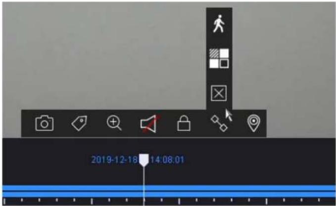
text_image
2019-12-18 14:08:01text_image
Face Picture Library List Smart Search > Face Picture Users Smart Event Settings > Engine Settings Smart Report > No. Name Total Pictures Normal Pictures Abnormal Pictures Edit Dot 1 about524 1 1 0 abust524Smarte begivenhedsindstillinger:
text_image
Smart Search Face Picture Library Smart Event Settings Face Capture Face Picture C... Camera [D1] ABUS IP Camera Enable Face Capture Sensitivity 1 5 3 Arming Schedule Linkage Action Continuous None Edit Mon 1 Tue 2 Wed 3 Thu 4 Fri 5 Sat 6 Sun 7 0 2 4 6 8 10 12 14 16 18 20 22 24 Applytext_image
ABUS Smart Search Face Picture Library Smart Event Settings Facial Recognition Camera D11 ABUS IP Camera Enable AI by NVR Engine Defect Intrusion Region Entrance Region Exiting Enable Tripwire Detection Defecton Area Settings Arming Schedule Linkage Action Arming Area 1 Direction: Ax>B Sensitivity 1 100 50 Defects: Human Vehicle Detection Ar Draw Area Clear All Size Filter Max. Size Min. Sizetext_image
Add IP Camera (Custom) No | Sta... | Security | IP Address | Device Model 1 - ✓ Active 192.168.0.244 IPCB64510B 2 ✓ Active 192.168.0.31 IPCB78521 3 ✓ Active 192.168.0.13 IPCB64521 IP Camera Address 192.168.0.244 Protocol ABUS Management Port 45003 Transfer Protocol Auto User Name installer Password Use Channel Default... Enable IP Camera T... Use Default Port ✓ Verify Certificate Search Continue to Add Addtext_image
Pse Power Configuration Pse Bonding Configuration Actual power: 10.7W. Remaining power: 109.3W. Channel Long Distance Short Distance Channel Status Actual Power D1 * Disconnected 0.0W D2 * Connected 3.0W D3 * Disconnected 0.0W D4 * Connected 4.7W D6 * Disconnected 0.0W D6 * Disconnected 0.0W D7 * Connected 3.0W D8 * Disconnected 0.0Wtext_image
A BUS Camera Display Drawing Camera Video Parameters Email Camera [D:\] ABUS IP Camera Enactive Clear Area 1 Clear Area 2 Clear Area 3 Clear Area 4 Clear All Applytext_image
I264 Camera Display Privacy Mask Video Parameters Main Stream Sub-Stream Event Camera [D:\I264\IP Camera Encoding Parameters Steam Type Resolution Bitrate Type Video Quality Frame Rate Max. Bitrate Mode Max. Bitrate(Kbps) Max. Bitrate Range Recom Video Encoding IFrame Interval Enable K 264+ Main Stream(Continuous) Video 3840*2100(MW) Variable Medium Full Frame Custom(32-16394) 12258 15246-16394(Kbps) K 264 50 Main Stream(Event) Video 3840*2100(MW) Variable Medium Full Frame Custom(32-16394) 12258 15246-16394(Kbps) K 264 50 Note: Different frame rate of continuous and event recording may cause problems in the exported AVI video.Her kan du justere videoparametrene for stream 1 (hovedstream) og 2 (substream).
text_image
ANSYS Camera Display Privacy Mask Video Parameters Event Motion Detection Video Tampering Video Loss Alarm Input Alarm Output Exception Camera USB ARSLS IP Camera Enable AI by NVR Enable Area Among Schedule Linkage Action Sensitivity 0 100 60 Detects Human Vehicle Draw Area Clear Applytext_image
ABUS Motion Detection Video Tampering Video Loss Alarm Input Alarm Output Exception Camera TOP ARUS IP Camera Enable AI by NVR Enable Area Arming Schedule Linkage Action Sensitivity 0 100 60 Detecti... Human Vehicle Draw Area Clear Applytext_image
A BUS Schedule Capture Audio Record Storage Device SSU Management Storage Mode Auto Backup Advanced Camera No. [D:\] A BUS P Camera Enable Schedule Advanced Continuous Event Motion Det Alarm M/A M.S.A None Edit Non 1 Tue 2 Wed 3 Thu 4 Fri 5 Sat 6 Sun 7 0 2 4 6 8 10 12 14 16 18 20 22 24 Back Canceltext_image
ABUS Schedule Record Capture Audio Record Storage Device SSO Management Storage Mode Auto Backup Advanced Camera No. |D1|ABUS IP Camera Enable Schedule Advanced Continuous Event Motion Det Alarm M | A M & A None Edit Mon 1 Tue 2 Wed 3 Thu 4 Fri 5 Sat 6 Sun 7 0 2 4 6 8 10 12 14 16 18 20 22 24 *Note: Operation is invalid when the number of lime segments exceeds the limit (B) Apply Createtext_image
ABUS Schedule Storage Device FXO Management Storage Mode Auto Backup Advanced Space distribution: 1.40GB of 7.28GB available. 5.78GB 98MB 1.40GB System Reserved Face Picture Library Free Initialize Face Picture...Opbevaringstilstand
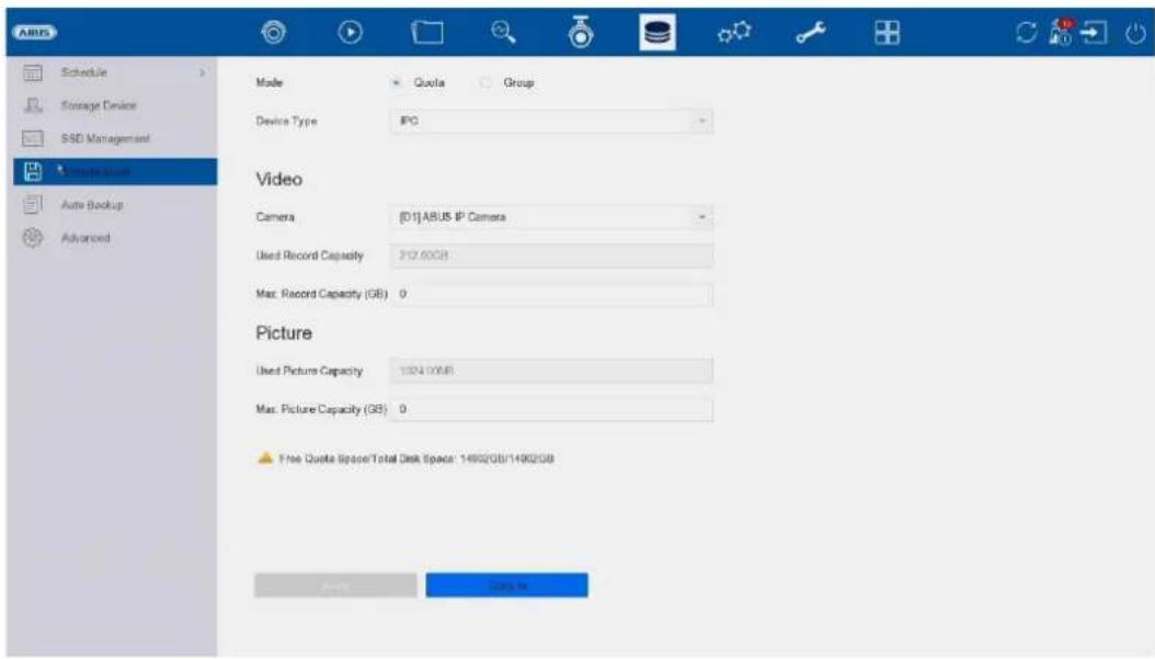
text_image
Schedule Storage Device SSD Management * Storage System Auto Backup Advanced Mode Quota Group Device Type IPC Video Camera [01]ABUS IP Camera Used Record Capacity P12.60GB Max. Record Capacity (GB) 0 Picture Used Picture Capacity 1324.00MB Max. Picture Capacity (GB) 0 Free Quote Space/Total Disk Space: 14902GB/14902GB Apply Canceltext_image
A BUS Schedule Storage Device R&D Management Storage Mode Auto Backup Advanced Backup Status Current Status Unplanned Last Backup Unplanned Auto Backup Settings... Auto Backup Start Backup at 00:00 Select Channel(s) for B... □ Select All □01 □02 □03 □04 □05 Backup Stream Type Main Stream Sub-Stream Dual Stream Backup to USB Select Device Overwrite Enable Enabletext_image
ABUS General Network Live View Holiday Audio Management Add Modify Delete Live View Per... No User Name Security Priority User's MAC Address Permission 1 admin Weak Password Admin 00:00:00:00:00 adminBrugeradministration finder sted i menuen "Bruger".
text_image
A#US General Add Modify Delete Live View Per... No. User N 1 admin Edit User User Name admin Password Modify User's MAC Ad... 00 00 00 00 00 00 Unlock Pattern Enable Unlock Pattern Reserved E-mail t****@lot.ie Modify GUID File Export Security Quest... OK Cancel User's MAC Address Permission 00:00:00:00:00:00text_image
ABUS General User Network TCP/IP Alternative Live View > Holiday Audio Management Email Cloud Service More Settings Log Server Settings Preferred SMTP SMTP Server SMTP Port 25 Enable SSL/TLS Server Authentication User Name Password Alternate SMTP: Enable SMTP Server SMTP Port 25 Enable SSL/TLS Server Authentication User Name Password Other configuration: Sender Sender's Address Select Receivers Receiver 1 Receiver Receiver's Address Attached Image Interval 2s Capt Applytext_image
ABUS General User Network: TCP/IP Maintenance Live View Holiday Audio Management Email Cloud Service More Settings Log Server Settings Access Type AUS Link Status Enable Stream Encryption Verification Code/Encryption... Registration Status Offline Account Status Unlinked Unbindtext_image
ARIS General User Networks Live View General View All-in-and-Stream Holiday Audio Management Video Output Interface 100% Live View Mode 1 * 1 Dwell Time No Switch Enable Audio Output Volume 1 5 3 Event Output HDMI Full Screen Monitoring Dwell Time 10s ApplyGenerelt
text_image
A BUS General User Network Live View General View All in one stream Holiday Audio Management Enable All-in-one-Stream Encod Fprime Rate Full Frame Max. Bitrate Mode General Max. Bitrate(Kbps) 1792 Applytext_image
System Info Import/Export Upgrade Default Network HDD Operation System Service Time 2024-06-26 00:00:00 2024-09-28 23:59:59 Major Type All Minor Type Select All ✓ Alarm Input ✓ Alarm Output ✓ Motion Detection Started ✓ Motion Detection Stopped ✓ Video Tampering Detection Started ✓ Video Tampering Detection Stopped ✓ Image Detection Detection Alarm Started ✓ Image Detection Detection Alarm Stopped ✓ Detrainer Detection Alarm Started ✓ Detrainer Detection Alarm Stopped ✓ Auto Input Exception Alarm Started ✓ Auto Input Exception Alarm Stopped ✓ Subtion Change of Sound Intensity Alarm Started ✓ Subtion Change of Sound Intensity Alarm Stopped ✓ Face Capture Alarm Started ✓ Face Capture Alarm Stopped ✓ Detrout Detection Alarm Started ✓ Detrout Detection Alarm Stoppedtext_image
System Info Log Info Import/Except Upgrade Home B Networks HCD Operation System Service Recover Defaults Reset all settings to factory default except network and admin password settings Factory Defaults Reset device to inactive status and all settings including network and password: Restore to inactive Loose all settings unchanged except restore device to inactive status without admin passwordtext_image
AIDS System Info Log Info Import/Export Upgrade Default Network Switch Network Detection Network Shell HDD Operation System Service bond0 Sending 9.863Kbps Receiving 9.126Kbps Name Linking Status Type MAC Address MTU(0) NIC Type Traffic bond0 Suaded Bond Sc 11:ab Of Sc d2 1500 1000M Full-diptext_image
ADRUS System Info Log Info Input/Object Upgrade Default Network HDD Uptition System Info End Anchor Detection Health Detection System Service Continue to use this disk when self-evaluation is failed. HDD No. Self-Test Type Short Test Soft-Test Net Insted Temperature(℃) 38 Self-Evaluation Pass Working Time (Gray) 165 AI-Evaluation Functional S.M.A.R.T Info ID Attribute Name Status Flags Download Value Start Save Value 0x1 Raw Reset Error Ro. OK 15 44 82 64 14976040 0x2 Spin Up Time OK 3 0 88 88 0 0x4 Reset/Step Count OK 50 20 100 100 58 0x5 Reallocated Sector OK 51 10 100 100 0 0x7 Seek Error Rate OK 15 45 76 60 44403457 0x8 Power-on Hours C. OK 50 0 96 96 3988 0x9 Spin Up Entry Count OK 19 97 100 100 0 0x10 Power Cycle Count OK 50 22 100 100 54 0x12 Unknown Tree Val... OK 11 50 100 100 0text_image
System Info Log info Impact/Export Upgrade Default Networks HCO Operation System Service System Services ONVP Stream Authentication Address Filter Device Auto Maintenance Double Verification Runner Settings Move Settings Enable RTSP RTSP Authentication Type digest RTSP Digest Algorithm MD6 Enable BAP1 Enable HTTP HTTP Authentication Type digest HTTP Digest Algorithm MD6 Enable IP Camera Occupation Detection Enable IOT Monitoring Enable SDK Service Enable Enhanced SDK Service Enable USB ReductONVIF:

text_image
Oracle OYMF Authentication Type: Upgrade No User Name Security Level Edit Delete User Name Security Level Edit Delete Show Exchange Address Filter Device Auto Maintenance Disable Audio Settings Bumper Settings Move Settings Addtext_image
Enable EBITAM Encryption Encryption Password The stream encryption key is synchronized with the ASUS Link Station service verification code. After enabling the encryption code, the ASUS Link Station stream will be forcedy encrypted. More sure the ASUS Link Station service supports stream decryption.text_image
System Info Log Info Import/Export Upgrade Default Network HDD Operation System Services System Services ONPF Simulera Energyplus Options Device Auto Maintenance Double Verification Stutter Settings Note Settings Enable Restriction Mode + IP Address + MAC Address Restriction Type Allow + Fixed Restriction List + Add + Edit + Delete No IP Address Savetext_image
ABUS System Info Log Info Import/Export Upgrade Default Network HDD Operation System Service System Service ONVIF Stream Encryption Address Filter Drive Active Maintenance Double Verification Buzzer Settings More Settings Enable Schedule Reboot Applytext_image
ARMOS □Enable Double Verification System Info Log Info Import/Export Upgrade Default Network HOLD Operation System Operator System Service CMVIF Stream Encryption Address Filter Device Auto Maintenance SQL Server Suzzer Settings Move Settingstext_image
System Info Log Info Import/Export Upgrade Default Network HDD Operation System Service System Service ONVF Stream Encryption Address Filter Device Auto Maintenance Disable Verification Burst Services More Settings Enable BuzzerNVR'ens integrerede piezo-bip kan aktiveres/deaktiveres helt her.
Flere indstillinger:
Aktiver/deaktiver tidssynkronisering: