
TVVR36302 - VCR ABUS - Free user manual and instructions
Find the device manual for free TVVR36302 ABUS in PDF.

| Product type | Network Video Recorder (NVR) for IP cameras |
| Brand | ABUS |
| Model | TVVR36302 |
| Number of channels | 4 IP channels (according to manual) |
| Maximum recording resolution | 8 MP (2560 x 1440) |
| Video compression | H.264, H.265, H.264+ |
| Local storage | Built-in hard drive (not included), up to supported capacity |
| Network storage | NAS (NFS), IP SAN (iSCSI) |
| Video outputs | VGA, HDMI |
| Output resolution | 1920x1080 (1080p) |
| Network functions | TCP/IP, DHCP, DDNS, PPPoE, NAT, NTP, UPnP |
| Remote access | ABUS Link Station (cloud), CMS, Web browser |
| Supported protocols | RTSP, HTTP, ONVIF (compatible with ABUS and other brands) |
| Audio | Audio input/output (RCA), built-in speaker |
| Motion detection | Yes, adjustable per camera |
| Intelligent video analysis | Line crossing detection, intrusion, facial recognition |
| User management | Multi-user with differentiated rights (Administrator, Operator, Guest) |
| Alarms | Alarm output, email notification, CMS push, local sounder |
| Maintenance | Clean with a dry, lint-free cloth; do not use chemicals |
| Security | Password protection, stream encryption, privacy functions (masks) |
Frequently Asked Questions - TVVR36302 ABUS
User questions about TVVR36302 ABUS
0 question about this device. Answer the ones you know or ask your own.
Ask a new question about this device
Download the instructions for your VCR in PDF format for free! Find your manual TVVR36302 - ABUS and take your electronic device back in hand. On this page are published all the documents necessary for the use of your device. TVVR36302 by ABUS.
USER MANUAL TVVR36302 ABUS
TVVR36302 / TVVR36402
TVVR36702 / TVVR36802
natural_image
Exterior view of a black and white ASUS audio device (no visible text or symbols on body)UK Local user interface instructions
natural_image
Exterior view of a black and silver ASUS audio workstation (no visible text or symbols on body)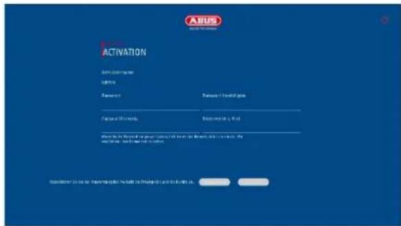
natural_image
Exterior view of a black and silver ASUS audio device (no visible text or symbols on body)EN Local user interface instructions
Original operating instructions in German. Keep for future use.
Version 04/2025
CE
Table of contents
- Declaration of conformity.... 50
- Explanation of symbols.... 51
- Safety instructions 52
- Intended use.... 53
- Setup wizard.... 54
- Live view....54
6.1 Main menu 56
6.3 Camera command....57
6.4 Display menu....57
- Playback view....58
7.1 Camera selection 58
7.2 Calendar....58
7.3 Camera command....59
7.4 Playback control....59
Time representation Timeline 59
Timeline control 59
- File search....60
- System settings 61
9.1.1. System / General 61
9.1.2. System / Live view 63
General....63
Layout / Advertisements 64
Channel zero 64
9.1.3. System / User 65
Add user 65
Change user....66
Delete user 66
NTP (simple mode)....66
9.2. Network 67
9.2.1 TCP/IP 67
9.2.2 DDNS 68
9.2.3 PPPoE 69
9.2.4 NAT 69
9.2.5 NTP 69
9.2.6 Protocol server setting.... 69
9.2.7 Further settings.... 70
9.2.7 Cloud access / ABUS Link Station.... 71
9.2.8 E-mail 72
9.3. Camera 73
9.3.1. Add IP camera 73
9.3.3. Private zone 75
9.4. Event 75
9.4.1. Normal event.... 75
9.4.2. Perimeter protection.... 76
9.4.3. Face recognition.... 77
9.5. Intelligent search / people search.... 78
9.6. Storage....79
9.6.1. Schedule 79
Extended 79
9.6.2. Stream settings 80
9.6.3. Memory 80
Add network drive....81
9.6.4. Storage mode....83
9.6.4.1. Mode: Contingent 83
9.6.5. Advanced settings.... 84
9.7. Facial image library 84
- Maintenance settings 85
10.1. System info....85
10.2. Firmware update.... 85
10.3. Restore / Reset 85
10.4. Logbook 86
10.5. System maintenance 87
- Maintenance and cleaning 88
11.1. Maintenance 88
11.2. Cleaning 88
- Waste disposal 88
- Technical data 89
- Open Source license information 89
1. Declaration of conformity
ABUS Security Center hereby declares that the enclosed product complies with the following guidelines concerning the product:
EMC Directive 2014/30/EU
Low Voltage Directive 2014/35/EU
RoHS Directive 2011/65/EU
The complete EU Declaration of Conformity can be obtained from the following address:
ABUS Security Center GmbH & Co. KG
Linker Kreuthweg 5
86444 Affing
GERMANY
www.abus.com/product/Artikelnummer
("Article number" in the link is identical to the article number
of the enclosed product)

Disclaimer
These operating instructions have been compiled with the utmost care. However, should you notice any omissions or inaccuracies, please let us know in writing at the address given on the back of the manual.
ABUS Security Center GmbH & Co. KG accepts no liability for technical and typographical errors and reserves the right to make changes to the product and operating instructions at any time without prior notice.
ABUS Security-Center is not liable or responsible for any direct or indirect consequential damages arising in connection with the equipment, performance and use of this product. No guarantee is given for the content of this document.
2. Explanation of symbols
 | The symbol with the lightning bolt in the triangle is used when there is danger to the health, e.g. due to electric shock. |
 | An exclamation mark in the triangle indicates important information in these operating instructions that must be observed. |
 | This symbol can be found when you are to be given special tips and information on operation. |
Important safety instructions
 | Damage caused by failure to observe these operating instructions will invalidate the warranty. We accept no liability for consequential damage! |
 | We accept no liability for damage to property or personal injury caused by improper handling or failure to observe the safety instructions. In such cases, all warranty claims are void! |
 | When using the recorder, please observe country-specific regulations on the protection of personal data. |
Dear customer, the following safety and hazard information is intended not only to protect your health, but also to protect the appliance. Please read the following points carefully:
- There are no serviceable parts inside the product. Disassembly also invalidates the approval (CE) and the guarantee/warranty.
• The product can be damaged by falling from even a small height. - Mount the product in such a way that direct sunlight cannot fall on the device's image sensor. Observe the installation instructions in the corresponding chapter of these operating instructions.
- The device is designed for indoor and outdoor use (IP66).
Avoid the following adverse ambient conditions during operation:
- Moisture or excessive humidity
• Extreme cold or heat - Direct sunlight
- Dust or flammable gases, vapors or solvents
- strong vibrations
• strong magnetic fields, such as in the vicinity of machines or loudspeakers. - The camera must not be installed on unstable surfaces.
General safety instructions:
- Do not leave the packaging material lying around carelessly! Plastic film/bags, polystyrene pieces etc. could become dangerous toys for children.
- For safety reasons, the video surveillance camera must not be given to children due to small parts that can be swallowed.
- Please do not insert any objects through the openings into the inside of the appliance
- Only use the additional devices/accessories specified by the manufacturer. Do not connect any incompatible products.
- Please observe the safety instructions and operating instructions for the other connected devices.
- Check the appliance for damage before commissioning; if this is the case, please do not operate the appliance!
- Observe the limits of the operating voltage specified in the technical data. Higher voltages can destroy the device and endanger your safety (electric shock).
3. Safety instructions
-
Power supply: Observe the information on the rating plate for the supply voltage and power consumption.
-
Overload
Avoid overloading mains sockets, extension cables and adapters, as this can lead to fire or electric shock.
- Cleaning
Only clean the appliance with a damp cloth without using harsh cleaning agents. The appliance must be disconnected from the mains.
Warnings
All safety and operating instructions must be observed before using the appliance for the first time!
-
Observe the following instructions to prevent damage to the mains cable and mains plug:
-
When disconnecting the appliance from the mains, do not pull on the mains cable, but grasp the plug.
• Make sure that the mains cable is as far away as possible from heating appliances to prevent the plastic sheathing from melting. -
Follow these instructions. Failure to do so may result in an electric shock:
-
Never open the housing or the power supply unit.
- Do not insert any metal or flammable objects inside the appliance.
-
To avoid damage caused by overvoltage (e.g. thunderstorms), please use overvoltage protection.
-
Please disconnect defective appliances from the power supply immediately and inform your specialist dealer.
 | When installing in an existing video surveillance system, make sure that all devices are disconnected from the mains and low-voltage circuits. |
 | If in doubt, do not carry out the assembly, installation and wiring yourself, but leave this to a specialist. Improper and unprofessional work on the power grid or domestic installations not only poses a risk to yourself, but also to other people.Wire the installations so that the mains and low-voltage circuits always run separately and are not connected to each other at any point or cannot be connected due to a fault. |
Unpacking
Handle the appliance with the utmost care when unpacking it.

If the original packaging is damaged, check the appliance first. If the appliance is damaged, send it back with the packaging and inform the delivery service.
4. Intended use
This recorder is used for indoor or outdoor video surveillance (depending on the model) in conjunction with a recording device or a corresponding display device (e.g. monitor or PC).
Any use other than that described above may result in damage to the product and other hazards. Any other use is not in accordance with the intended use and will invalidate the guarantee or warranty; all liability is excluded. This also applies if modifications and/or changes have been made to the product.
Read the operating instructions completely and carefully before using the product. The operating instructions contain important information for installation and operation.
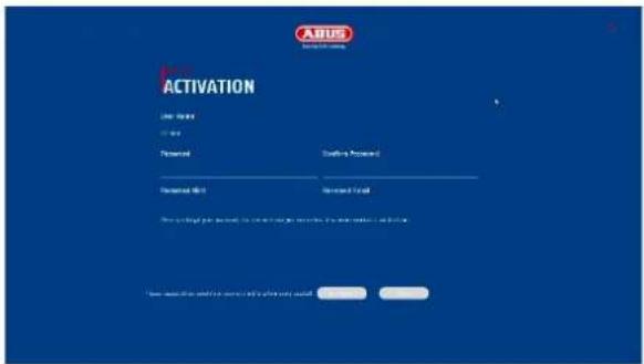
5. Setup wizard
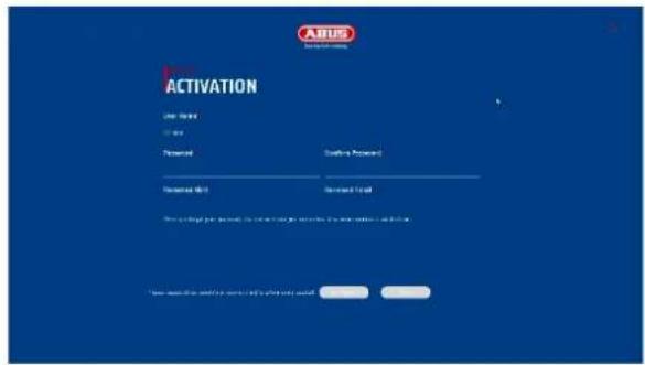
The setup wizard guides you through the necessary basic system settings. The recorder is then basically set up for recording and monitoring.
6. Live view
![ABUS File By: Not Summary Channel Target Deflection [01] ABUS IP Camera 04-2026 13:55:15 D1 D2 D3 D4 D5 D6 D7 D8 D9 D10 ( 1/1 ) D2 D3 D4 D5 D6 D7 D8 D9 D10](/content/2026/04/733202/images/fee78e5fad3730c1fb78cc36f7cc010819c02a177a76168d85a66004e9d8fdbb.jpg)
The live view starts automatically when the device is switched on.
This view offers the option of displaying or executing live images and camera commands from all connected cameras on the recorder.
- By double-clicking the left mouse button, you can the respective camera image as a full screen or switch back to the original view.
- By clicking the right mouse button, you can hide and show the menu structure to display only the respective camera layout as a full screen.
The live view is divided into the following functional areas:
| Main menu | Selection of the configuration and operating menus | |
| Camera menu | Select and search for cameras | |
| Camera command | Selection of the camera commands and actions of the selected camera. The red frame around the camera image shows that the camera is selected.The camera command bar appears at the bottom of the camera image. | |
| Display menu | Controlling the view on the local monitor | |
| Admission status | In the live image, the current recording status is always displayed (top right) in the form of a colored R ("Record"). Each video channel can have one of the following three statuses: | |
| No symbol | No recording programmed, no hard disk available, no event | |
 | Event(e.g. on movement) | |
 | Recording started | |
6.1 Main menu


Switches to the live view
Switches to the playback view
Switches to the file search
Switches to the menu for system settings
Switches to the menu for maintenance settings
Switching between simple mode / expert mode
Alarm information
Quick display of some important alarm events
Log out / shut down / restart
6.3 Camera command
| Display of the signal type and channel number (D1: IP channel 1) | ||
| Trigger single image recording | ||
 | Starts playback of the last 5 minutes | |
 | Opens the PTZ control | |
 | Opens the digital zoom | |
 | Switches audio on / off | |
| Intercom on / off | ||
| Live view options: this option determines whether the display is more fluid, but is displayed with a slight time delay (real time = little delay) | ||
| Switching between 1st and 2nd video stream. | ||
| Display VCA info (e.g. tripwire lines are displayed live in the image) | ||
| Self-adaptive resolution / display format: If a camera with an image ratio of 4:3 is connected, the camera image can be displayed stretched or unstretched. | ||
6.4 Display menu
 | Switches between view pages |
 | Opens the selection of camera layouts |
 | Starts / ends the sequence display |
 | Opens and closes the full-screen view |
7. Playback view
![ABUS Normal Event Slice 1 4 [D1] ABUS IP Camera [D2] IPCamera 02 [D3] IPCamera 03 [D4] IPCamera 04 << 2025 Apr >> S M T W T F S 30 31 1 2 3 4 5 6 7 8 9 10 11 12 13 14 15 16 17 18 19 20 21 22 23 24 25 26 27 28 29 30 1 2 3 4 5 6 7 8 9 10 DO:00:00 2 3 4 5 6 7 8 9 10 11 12 13 14 15 16 17 18 19 X:1 X:24 < > As h](/content/2026/04/733202/images/594742e4efdcf8d08f000319d4c9c90f77edab7ae33c00ecb906d0acd4a08699.jpg)
Playback enables the recorded video data from cameras to be played back on the recorder.
The playback view is divided into the following functional areas:
| Camera selection | Selection of the cameras to be played back. |
| Calendar | Selection of the date of the recorded data. |
| Camera command | Selection of camera commands and actions for the selected camera. |
| Playback control | Control and interaction during playback. |
7.1 Camera selection
The camera list is used to select the recorded camera archives on the recorder. Several cameras can be played back simultaneously by clicking on the selection fields in the list.
7.2 Calendar
In the calendar, you can directly select the day for the recording to be searched. A triangular mark on the day means that recordings are available.
7.3 Camera command
| Display of the signal type and channel number (D1: IP channel 1) | ||
| Trigger single image recording | ||
 | Opens the digital zoom | |
 | Switches audio on / off | |
 | Add marker (tag) | |
 | The recording file of the current playback position is locked. A locked file is not overwritten by the ring buffer. | |
| Fisheye extension: View selection for recordings from a fisheye camera | ||
 | Trimming and exporting video sequences | |
| Multi-window division: Display of playback data over 4 images with different time stamps. | ||
| Display VCA info (e.g. tripwire lines are displayed live in the image) | ||
| Self-adaptive resolution / display format: If a camera with an image ratio of 4:3 is connected, the camera image can be displayed stretched or unstretched. | ||
7.4 Playback control
Then click on the timeline to start / resume playback at the desired time. Recordings are indicated by colored bars in the timeline. The color coding is as follows:
| Continuous recording | |
| Event recording (movement, event) |
Time representation Timeline
The default setting for the display range of the timeline is 24 hours. The scaling of the timeline can be changed using the mouse wheel. To do this, hold the mouse pointer over the timeline and press the mouse wheel.
Timeline control
The following functions are available below the timeline:
| Jumps backwards for 30 seconds | |
| Jumps forward for 30 seconds | |
 | Play and pause the recording forwards |
 | Reduces the playback speed |
| X1 | Playback speed |
 | Increases the playback speed |
 | Opens and closes the full-screen view |
| Display filter for images of people, vehicles | |
| Intelligent search: | |
| People search |
8. File search
| Video | Search for saved videos via:- Period- Marking (tag)- Locking / Locked video sequences- Camera number |
| Image | Search for saved single images via:- Period- Camera number |
| Event | Search for saved videos via:- Event type (e.g. movement)- Period- Camera number |
| Human | Search for saved videos via:- Human event type- Period- Camera number |
| Vehicle | Search for saved videos via:- Event type License plate number- Period- Camera number- License plate designation |
Each search menu then offers the option of viewing or exporting video files (USB export).

The event type must be supported by the selected camera or recorder.
Unsupported event types do not provide any search results.
9. System settings
All basic device settings are managed in the "System" menu.
Attention: Make sure that the date and time have been set correctly. An incorrect setting can lead to functional restrictions (e.g. with the app connection).
Subsequent changes can lead to data loss! Make sure you back up your data in good time.
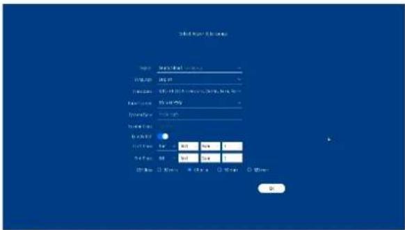
9.1.1. System / General
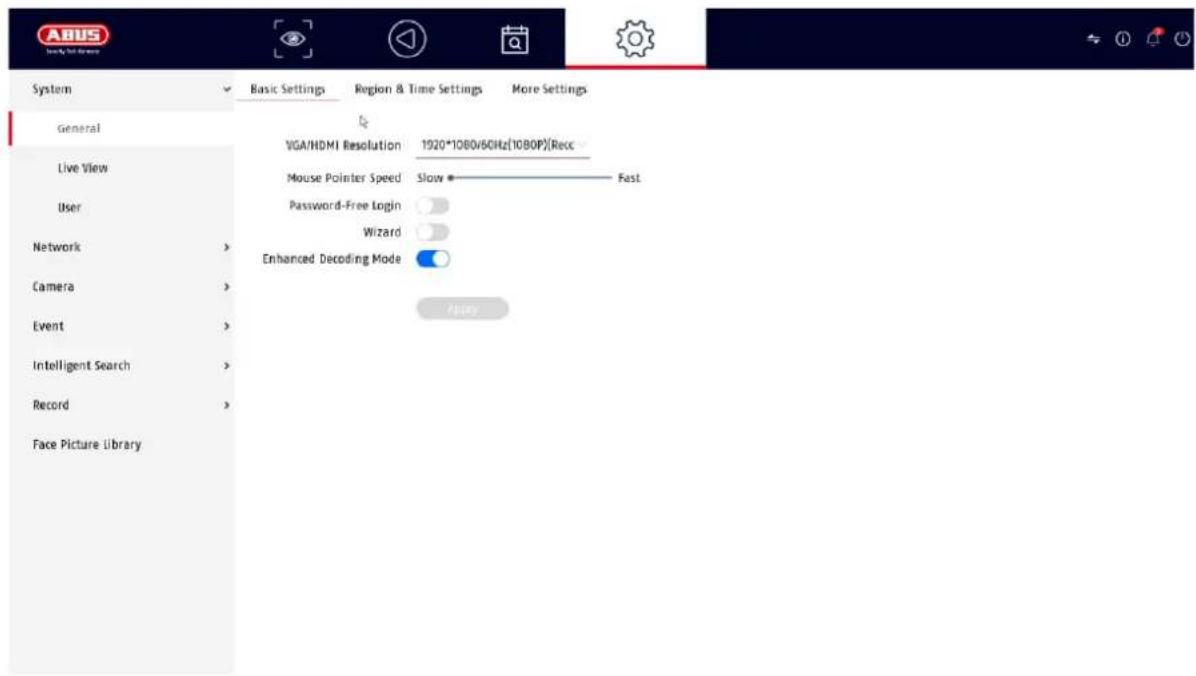
| VGA/HDMI resolution | Select the monitor resolution of the VGA and HDMI output |
| Speed of the mouse pointer | Sliding bar, low speed on the left, high speed on the right |
| Login without password | If this function is activated, no password query takes place after the recorder is started. If a user actively logs out, the query will take effect again. |
| Assistant | Select whether the wizard should appear at system startup. |
| Region | Country selection |
| Language | Select the menu language to be displayed |
| Time zone | Select the time zone in which you are located |
| Date Format | Select how the date should be displayed:MM-DD-YYYY, DD-MM-YYYY, YYYY-MM-DD |
| Date | Set the current date |
| Time | Set the current time |
| Activate summer time | Select whether the recorder should switch between summer and winter time. • Auto: Recorder changes automatically Manual: Recorder changes based on the set start/end date |
| Video quality module | Software-based blurring or overdrawing of the video display. |
| Local automatic login | Select the duration after which the menu is automatically closed: Never / 1 ... 30 minutes |
| Device name | Here you can assign a name/description for the recorder |
| No. | Used to uniquely identify the recorder when using a control panel |
| Protocol menu | Select the duration after which the menu is automatically closed: Never / 1 ... 30 minutes |
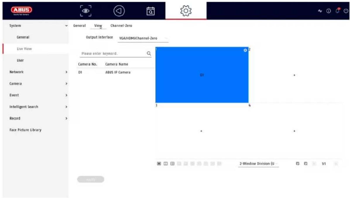
9.1.2. System / Live view
In the Live view menu, you define the behavior of the local image output on the recorder.

General
| Output menu | Here you can select the connection on which the settings are to be changed |
| Window layout | You can select the camera layout here:1x1, 2x2, 1+5, 1+7, 3x3, etc. |
| Automatic switching | Here you can select the switching time between the individual cameras for sequence display |
| Alarm pop-up output | Here you can define the monitor for the output of events |
| Alarm pop-up delay | Here you can define how many seconds the event should be displayed on the assigned monitor |
| Activate audio | Activates the audio output for the live view.VGA: if this option is selected, the audio is output via the cinch sockets on the rear of the recorderHDMI: if this option is selected, the audio is output via the HDMI interface |
| Volume | You can adjust the volume here |
Layout / Advertisements

Here you can define the camera layout for the selected monitor.
Note: Pay attention to possible limitations in the live view with regard to the local decoder performance of the recorder.
Channel zero
After activating this function, an additional channel is available in the web interface of the recorder which combines the first 4 analog channels in a quadrant image.
9.1.3. System / User
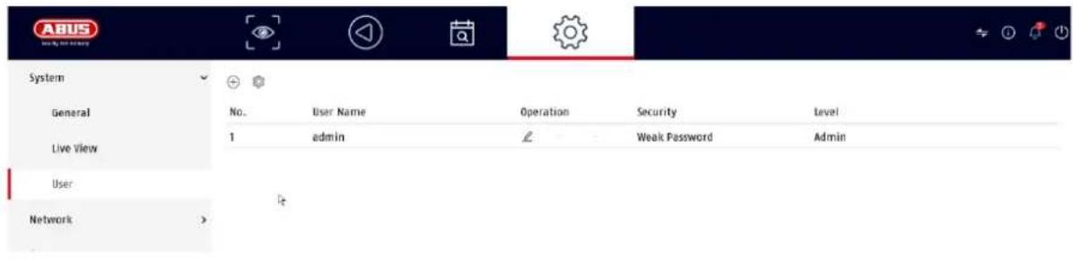
User administration takes place in the "Users" menu.
 | Add user |
 | Change user |
 | Delete user |
Add user
To add a user, click on the "+" symbol.
| User name | Choose a unique name |
| password | Choose a passwordNote: change passwords regularly, use combinations of letters, numbers etc., write down passwords in a safe place. |
| Confirm | Confirm the password |
| User authorization | Select the authorization level of the user.IMPORTANT:More rights can be set for theOperatorlevel than for theGuestlevel. |
Change user
To change the settings for a user, first select a user and then click on the "Change" icon.
The following changes can be made:
- User name
- password
- User authorization
Delete user
To delete a user, first select a user and then click on the "Delete" icon.
NTP (Simple mode)
The menu is available in simple mode (switch via the control bar at the top right). The Network Time Protocol (NTP) is used for automatic time synchronization via the network or Internet.
| Activate | Activate the NTP function on the recorder here |
| Interval (min.) | Select the interval for synchronization here |
| NTP server | Enter the IP address of the NTP server here |
| NPT port | Enter the port of the NTP server here |
Exception (simple mode)
Specific alarms can be set for certain exceptions. The following exceptions can be monitored.
- HDD (hard disk) full
• HDD (hard disk drive) error
• Network disconnected - IP conflict
- Illegal registration
- Recording error
The following alarms can be triggered due to exceptional circumstances:
• Audio warning (buzzer, local on the device)
- Notify CMS
- Send e-mail
9.2. Network
The complete network configuration of the recorder is carried out in the "Network" menu. The recorder must at least be physically connected to the network using a network cable. To ensure smooth network operation, we recommend continuous Gbit cabling between the recorder, camera and switch.
Note
The correct network settings are essential for integrating network cameras and accessing the recorder using remote software (browser, ABUS CMS, Link Station App).
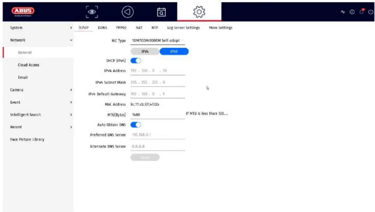
9.2.1 TCP/IP
Settings for the local network and selection of the network mode are defined here.
| NIC type | Set the transmission speed of the built-in network card here. Select "Self-adaptive" so that the recorder automatically determines the best possible speed. |
| Activate DHCP | Activate the checkbox if you assign the IP addresses in the network dynamically via DHCP.DHCP active: The following input fields are disabled as the parameters are obtained from DHCP.Note:If you assign the IP addresses manually, make sure that DHCP is not active (no tick in the checkbox') |
| IPv4 address | Enter the IP address of the network device in the network for manual assignment here |
| IPv4 subnet mask | Enter the subnet mask of the network device in the network for manual assignment here |
| IPv4 standard gateway | Here you enter the IP address of the gateway in the network for manual assignment, normally the IP address of the router |
| MAC address | Hardware address of the built-in network card |
| MTU (bytes) | Describes the maximum packet size of a protocol. |
| Preferred DNS server | IP address of the domain name server, normally the IP address of the router |
| Alternative DNS server | Alternative IP address of the DNS server |
| Obtain DNS server address automatically | Obtains the correct DNS server address automatically from the DHCP server |
9.2.2 DDNS
The DDNS function is used to update host names or DNS entries
| Activate | Activate DDNS synchronization here |
| DDNS type | Select the DDNS service provider here |
| Server address | Enter the IP address or host name of the DDNS provider here |
| Device domain name | If necessary, enter the sub-domain of the device here |
| Status | Display of the DDNS status |
| User name | Enter the user name of your DDNS account here |
| password | Enter the password for your DDNS account here |
If you want to use ABUS-Server for remote access, proceed as follows:
1) To be able to use the ABUS DDNS function, you must first set up a free account at http://www.abus-server.com. Please refer to the FAQs on the website.
2) Before activating the ABUS server DDNS function, please set up your ABUS devices correctly in the ABUS server with the respective MAC address.
3) Activate the DDNS function
4) Enter the user name and password of your ABUS server account
5) Click on "Save."
The NVR will now connect to the ABUS server account. This process can take up to 2 minutes. The ports are now automatically transmitted and updated in the ABUS server at regular intervals.
For external access to be possible and the port scan of the ABUS server to determine the "green" status, the respective ports must be enabled or forwarded in the router/firewall.
9.2.3 PPPoE
This function makes it possible to operate the recorder directly on a DSL modem. You can obtain the access data from your ISP (Internet Service Provider).
9.2.4 NAT
Network Address Translation (NAT) is used to separate internal and external networks.
ATTENTION: It is recommended to leave the AutoUPnP function set to "Manual". (assignment type).
| (UPnP) activate | Activate the checkbox to enable visibility in an IP network. If this function is activated, port forwarding is automatically entered in the router for all network ports (if UPnP is active in the router).If UPnP is activated, the network ports configured by UPnP (if ABUS DDNS is active) are transmitted to the ABUS server. |
| Assignment type | With the "Manual" setting, the network ports can be set manually using the "Edit" button.With the "Auto" setting, the recorder checks for free network ports on the router and sets the port numbers according to a random pattern. |
9.2.5 NTP
The Network Time Protocol is used for automatic time synchronization via the network.
Activate NTP: Activates the NTP function on the recorder Interval (min.): Defines the interval for synchronization. NTP Server: NTP server address NPT Port: NPT Port
9.2.6 Protocol server setting
In this menu it is possible to send log information to a "Sys Log Server".
9.2.7 Further settings
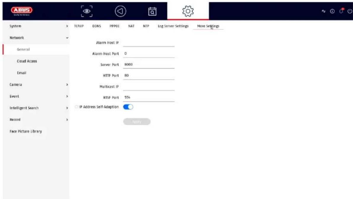
| Alarm Host IP | Network address of the CMS station |
| Alarm Host Port | Port of your CMS station (default: 7200) |
| Server Port | Port for data communication to ABUS CMS and iDVR App / ABUS LINK STATION APP (normal connection via IP) (Standard: 8000) |
| HTTP Port | Port of the web server (default: 80) |
| Multicast IP | You can also enter the multicast IP here to minimize traffic. The IP address must match the one in the video surveillance software. |
| RTSP port | Specify the RTSP port (default: 554) |
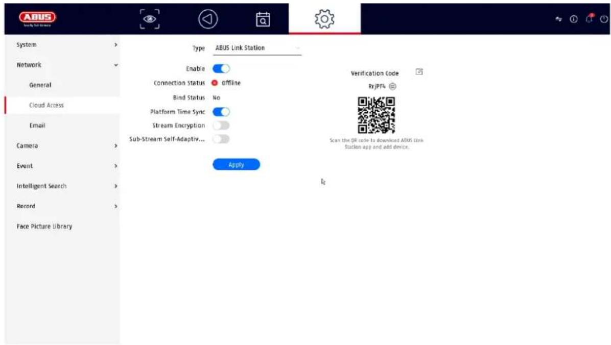
9.2.7 Cloud access / ABUS Link Station

The ABUS Link Station service allows simple and uncomplicated remote access, e.g. via a mobile device (without port forwarding).
Note: An Internet connection is mandatory to use this service.
| Activate | Activate checkbox to be able to use the service.After activation, a menu appears to enter the "Verification Code" for the first time and agree to the terms of use of the service. |
| Stream encryption | Here you can activate the encryption of data transmission. |
| Verification code | You can define the verification code here. This is requested by Remote when the connection is established to prevent access by unauthorized third parties. (If stream encryption is activated) |
| Status | Shows whether the recorder is connected to the ABUS Link Station service |
| ABUS Link Station account status | Shows whether the recorder is connected to an ABUS Link Station user account |
In the "ABUS Link Station" app, you can easily add devices by scanning the QR code of the device. You will find this QR code in the scope of delivery or you can use the QR code displayed here in the menu.
9.2.8 E-mail
These option settings are only available in simple mode (switch via the control bar at the top right).
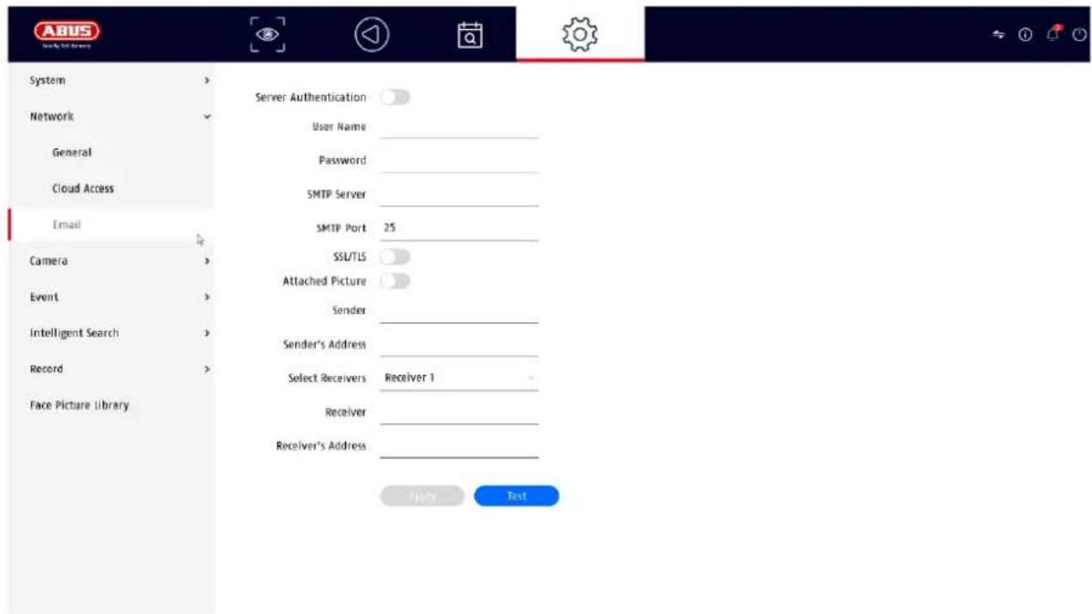
In the event of an alarm, the device can send a message by email. Enter the email configuration here.
| Server authentication | Activate checkbox if authentication on the server is required/necessary |
| User name | Enter the user name of your e-mail account here |
| password | Enter the password from your e-mail account here |
| Sender | Enter the sender's name here |
| Sender address | Enter the e-mail address associated with the e-mail account here |
| Select recipient | Here you can select up to 3 different recipients and then enter their e-mail addresses |
| Receiver | Enter the name of the recipient here |
| Recipient address | Enter the e-mail address of the recipient here |
| Attach picture | Activate checkbox if camera images are to be sent as photo files in addition to the e-mail |
| Interval | Select a trigger time between 2 and 5 seconds here. The images are only sent when motion has been detected over the defined period. |
| SMTP Server | Enter the SMTP server address of the e-mail provider here |
| SMTP Port | Enter the SMTP port of the e-mail provider here |
| Activate SSL/TLS | Activate 'Checkbox' to activate e-mail encryption |
9.3. Camera
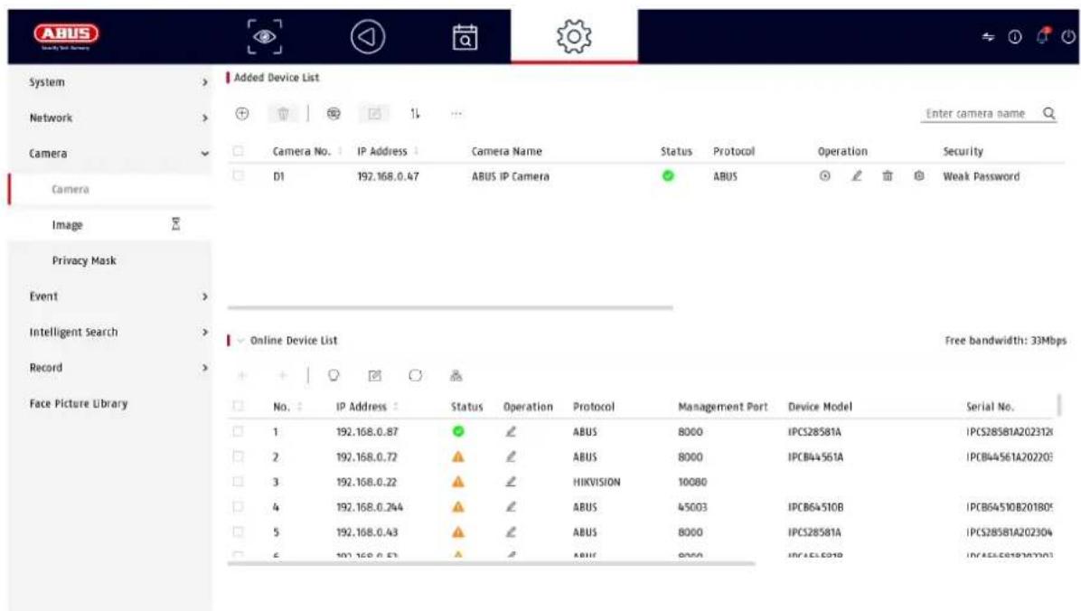
9.3.1. Add IP camera
The connection data for IP cameras can be configured in this menu item.
At the bottom of the page is a menu for searching for IP cameras connected to the network. An automatically found IP camera can be added to the recorder using the + symbol. The device and its details are listed in the upper area. The number of possible cameras depends on the recorder and the set mode (see data sheet).
If the IP address, the user name, the password and the port (ABUS standard = 8000, for other manufacturer protocols the port may differ, e.g. 80) are known, a camera can also be added manually.
9.3.2. Picture (settings)
![ABUS System Network Camera Camera Name [01] ABUS IP Camera Camera Image Privacy Mask Event Intelligent Search Record Face Picture Library OSD Settings Display Name Display Date Date Format DD-MM-YYYY Time Format 24-hour Display Mode Non-Transparent & Not Flat > Image Settings Exposure > Day/Night Switch > Backlight > Image Enhancement](/content/2026/04/733202/images/9620e59e2882872add6fec0d614eaa2d2b963bef204be838f1780e1440ffdb88.jpg)
Here you have the option of making individual settings for the camera display for each camera. The camera name and date & time can be positioned directly in the displayed live image.
Please note: The selection of setting options may vary depending on the camera model used.
For more information on the settings, please refer to the camera operating instructions.
| Camera | Select the camera to be set |
| Camera name | You can change the name of the camera here |
| OSD | Here you can select what is to be displayed in the camera image and in which format:Name, date, day of the week |
| Image | Here you can adjust the brightness, contrast and saturation of the image.Depending on the installation of the camera, it may be necessary to make the following settings:Corridor mode: Rotates the image by 90°Mirror mode: Tilts or mirrors the image. |
| Exposure | You can adjust the camera's exposure time here |
| Day/night switching | Here you can adjust the behavior of the day/night switchover and activate/deactivate SMART-IR. |
| Backlight | Here you can adjust the WDR behavior of the camera |
| Image enhancement | Here you can adjust the digital noise reduction (DNR) of the camera |
9.3.3. Private zone
Here you can create up to 4 privacy zones per camera. By clicking on the "Activate" checkbox, you can create and delete the privacy zone directly in the live image displayed.
9.4. Event

In the "Event" menu, you define which reactions are to be triggered in the event of an event (e.g. motion detection).
For some events, it is necessary to define an area, sensitivity and schedule (when this event should be monitored). You can also select the following "linking actions" in response to the event.
| Full screen monitoring | Displays the triggered camera as a full screen on the local monitor. (Configuration of the full screen output under "System" / "Live view") |
| Audio warning | Starts a warning tone on the recorder |
| CMS / Link Station Push | Sends a push message to the ABUS CMS or ABUS Link Station app |
| Send e-mail | Sends an e-mail (the recipients + SMTP must be set up first) |
| Trigger alarm output | Not supported |
The "Trigger channel" defines which cameras are triggered and recorded in the event.
9.4.1. Normal event
The following events can be set up in the "Normal event" menu:
![ABUS System Network Camera Event Normal Event Perimeter Protection Face Recognition Intelligent Search Record Face Picture Library Motion Detection Video Tampering Video Loss Alarm Input Alarm Output Flashing Light Alarm Output Audio Alarm Output Camera [D1] ABUS IP Camera Enable VCA Mode By Camera Area Arming Schedule Linkage Action Sensitivity 80 Full Screen Clear Apply](/content/2026/04/733202/images/8c393d8538d4d0c8094f267479410f680e1d0be76584488e69a5c9f6531d5cb1.jpg)
| Motion detection | The event can be performed directly by the camera (if supported), or it can be performed by the recorder.If a live image from the camera is displayed in this dialog, you can configure the camera's motion masks directly.Note: The displayed settings for motion detection are basic settings. Detailed settings may be offered in the web interface of the IP camera. |
| Sabotage monitoring | The tamper monitoring function monitors the brightness value of the selected camera. If the lens is covered, the trigger is activated. |
| Video loss | The video loss function monitors the selected camera for image loss. If the camera can no longer be reached via the network, the trigger is activated. |
| Alarm input | Only supported for IP cameras with alarm input. |
| Alarm output | Only supported for IP cameras with alarm output. |
| Flash alarm | Only for IP cameras that have a built-in flash |
| Audio alarm | Only for IP cameras that have a built-in speaker |
| Exception | The Exception function defines the behavior of the recorder for warning messages and system events. |
9.4.2. Perimeter protection
The settings pages for intelligent or VCA events (Video Content Analysis) are loaded and displayed dynamically depending on the connected IP camera.
The VCA events can be performed directly by the camera (if supported), or they can be performed by the recorder.
Note: For more information on the settings in the IP cameras, please refer to the camera operating instructions.
Tripwire:
Direction-dependent analysis of the crossing of a line (max. 1 line). The analysis can also differentiate between people and vehicles. Maximum and minimum sizes of the objects to be detected can be set. Schedule programming possible. Alarm pop-up, acoustic alarm, ABUS CMS notification, e-mail dispatch, recording possible.
Intrusion Det: Analysis of entry into an area. The alarm can be triggered X seconds after entry (limit value setting). The analysis can also differentiate between people and vehicles. Maximum and minimum sizes of the objects to be detected can be set. Schedule programming possible. Alarm pop-up, acoustic alarm, ABUS CMS notification, e-mail dispatch, recording possible.
9.4.3. Face recognition
These functions deal with the recognition of faces, whereby faces are captured as a facial feature model.

The recording of faces / face models is not verified or checked, i.e. a recorded is not checked for authenticity. The function can therefore be manipulated (e.g. pointing out pictures of people).

When using the function, please observe country-specific regulations on the section of personal data.
Info on the function sequence
The recognition of a face is started when the person enters the scene. Several face models are then created in series, and the model with the highest information content is processed further after the person leaves the scene.

The face recognition process is therefore only completed after the person has the scene. Please note this behavior when using the function.
| Face detection | Faces that enter and leave the camera scene are recognized and saved as individual images and video sequences. All recognized faces can then be searched for. |
| Comparison of facial images | Faces entering and leaving the camera scene are compared with a database stored in the recorder. In the event of a positive or negative comparison with the database, various events can beprogrammed (alarm pop-up on the local monitor, acoustic warning on the recorder, notification to the ABUS CMS software, e-mail dispatch, switching alarm output to camera, PTZ link, linking of audio or flashing light actions).For this function, facial images must be uploaded to the recorder's image database. This is done in the menu item "Face image library" (image format JPEG or JPG, file size less than 1 Mbyte, resolution 64x64 - 1920x1088). |
Minimum pupil distance: 30 pixels
Maximum pupil distance: 700 pixels
Example: Distance to face with camera with 1920 x 1080 pixels @ 2.8 mm focal length (approx. 110 degrees): approx. max. 4 meters
9.5. Intelligent search / people search
This function is not currently supported by any ABUS cameras. All detected persons can be filtered in the event search under "Human". On the playback page, there is also a filter for "Human" on the left under the recording bar.
9.6. Storage
9.6.1. Schedule
![Camera No. [D1] ABUS IP Camera Enable Continuous Event Mon Tue Wed Thu Fri Sat Sun 0 2 4 6 8 10 12 14 16 18 20 22 24 Advanced>> Apply Copy to](/content/2026/04/733202/images/28e2fe88815c9fb4122d1d7906b55901446fb93316495c81c61fd550cd5735fe.jpg)
In this menu, you define the schedule and the triggers for recording videos or pictures.
First activate the schedule, click on a trigger and then hold down the left mouse button and drag in the weekly calendar to define the desired times.
| Continuous | Continuous continuous recording |
| Event | Each type of event (movement or VCA events) is recorded |
| None | There is no recording |
| Edit | Here you can edit the settings in list form |
The following settings can be made by clicking on the "Advanced" button.
Extended
| Record audio | Activates audio recording (if the camera provides an audio signal and the stream is set to "Video & Audio") |
| Pre-alarm | Activate the pre-alarm recording hereNote: Depending on the system configuration and number of cameras, a storage time of up to 10 seconds can be achieved. |
| Post-alarm | Select the duration for the post-alarm storage for event recordings |
| Stream type | The 1st and 2nd video streams are always recorded |
| Procedure (days) | Specify how many days the recordings should be kept before they are overwritten |
9.6.2. Stream settings
![System Network Camera Event Intelligent Search Record Schedule Parameters Storage Storage Mode Advanced Face Picture Library Camera [01] ABUS IP Camera Main Stream Sub-Stream Stream Type Video Resolution 2500*440(Kbps) Bitrate Type Variable Video Quality Medium Frame Rate Full Frame Max. Bitrate Mode Custom(32-1638A) Custom(32-1638A) Max. Bitrate(Ibps) 6144 6144 Recommend 7/00-12000(Kbps) 7/00-12000(Kbps) Video Encoding: H.25% Enable H.25% Copy to Copy to](/content/2026/04/733202/images/bcc649240700e72938a055f21d650fab99bbb8d200b597a2a1f6debd2fbdbbfe.jpg)
Here you can adjust the video parameters for stream 1 and 2.
Note: For more information on the settings, please refer to the camera operating instructions.
9.6.3. Memory
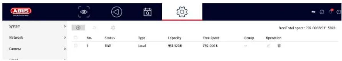
Here you can configure local or network-based storage media and view their status.
| Add | Add network drive |
| Initialize | Initialize (format) memory |
| Repair database | Rebuilds all databases, the files are not deleted. |
| Total | Displays the total memory space |
| Available | Displays the total free memory space |
Attention: Before you can make recordings with the device, the built-in hard disk must be "initialized". All hard disk data will be deleted during initialization!
No. Number of installed hard disks / added NAS drives
| Capacity | Displays the storage space in GB |
| Status | Shows the current status of the hard disks:Not initializedNormalFaultySleeping (=standby) |
| Properties | Displays the access status of the hard disk:Read only: Write protectionReading/writing: Reading and writing |
| Type | Displays the connection type of the hard disk:Local: Device hard diskNAS: Network hard disk (NFS)IP SAN: iSCSI Volume |
| Memory | Displays the free memory space |
| Group | Shows which group the hard disk is assigned to |
| Editing | You can change the group assignment and access status hereHDD No.: Internal numbering of the hard disksR/W: In this mode, video data is written to the hard disks and can also be read (default setting)Read only: In this mode, no video data is written to the data carrier. This setting is helpful if you want to prevent the data from being overwritten after an event.Redundant: In this mode, video data is saved redundantly on all data carriers with the "Redundant" setting. To do this, the "Redundant" button must be set in the "Recording→ Parameters→ Further settings" menu.Group: Assignment of the hard disk to an HDD group |
| Delete | Deactivate / activate hard disk |
Attention: If only one hard disk is installed and it has the status "Read only", the device cannot make any recordings!
Add network drive
Click on "Add" (+ sign top left) to add a network drive.
Attention: It is recommended to use a separate volume on the NAS for each NVR, as multiple use could lead to problems.
| Network drive | Choose between 8 network drives. |
| Type | • NAS: Your network storage must support the NFS file system for this setting.• IP SAN: Your network storage must support the iSCSI protocol for this setting. |
| IP address | Enter the IP address of the network storage device here. |
| Directory | Click on "Search" to select the path or enter it directly. |
9.6.4. Storage mode
![System Network Camera Event Intelligent Search Record Schedule Parameter Storage Storage Mode Advanced Face Picture Library In quota mode, the videos of channel shares no quota will be overlapped. You need to allocate channel with valid quota or switch to group mode. Mode Quota Camera [D1] ABUS IP Camera Used Record Capacity 38.00GB HDD Capacity 931GB Record Capacity (GB) 0 ▲ Free quota space: 931 GB, used picture space: $120.00MB. Apply Copy to](/content/2026/04/733202/images/823dcd103af96ca79aa6af86c1810420939dfc39857445410bd9538f23772259.jpg)
In this menu, you set the storage mode of the recorder. Two different storage modes are available to either distribute video data to all hard disks or to enable specific write operations to individual data carriers.
9.6.4.1. Mode: Contingent
In this mode, the video data is written distributed over the total number of all connected data carriers.
| Camera | Select the camera |
| Video memory used | Currently used video memory on the data carrier network |
| Used image memory | Currently used image memory on the data carrier network |
| HDD capacity (GB) | Shows the total storage space in GB |
| Reserved memory "Video" | Set the maximum recording size for video on the data carrier network per camera |
| Reserved memory "Pictures" | Set the maximum recording size for images on the data carrier network per camera |
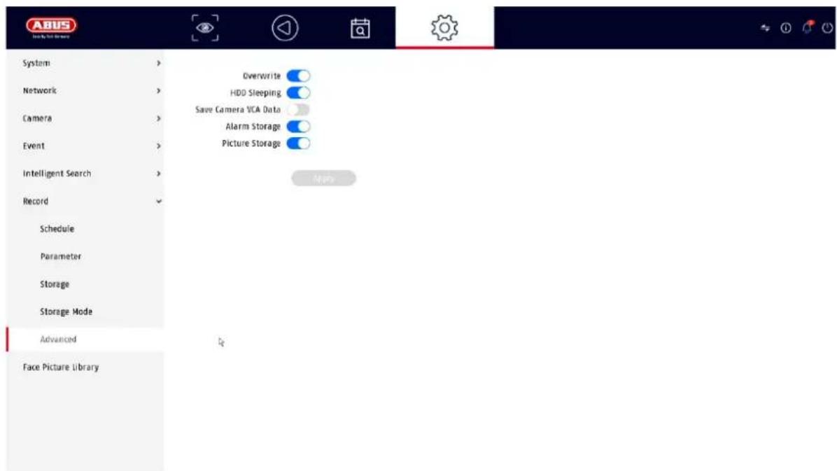
9.6.5. Advanced settings
Here you can make general settings for all installed hard disks.
| Overwrite | Specify whether older recordings should be overwritten when the hard disk is full. |
| Hard disk hibernation | When this function is activated, hard disks that are idle go into standby mode. |
| Saving the camera's VCA data | If the video content analysis data (VCA) comes from the camera, this can also be saved in the recorder. |
| Alarm memory | Activate alarm storage |
| Image memory | Activate storage of individual images for alarms |
9.7. Facial image library
The "Compare face images" function requires the creation of at least one face database. JPEG images of faces in a specific format are uploaded to this database and the recorder then models these images. This can take several minutes after uploading.
Up to 16 face databases with up to 20000 images / max. 1 GByte in total can be created (image format JPEG or JPG, file size less than 1 Mbyte, resolution 64x64 - 1920x1088).
In the settings page for the "Compare face images" function, only 1 database can be selected at a time.
10. Maintenance settings
In this menu, you can export and import important status information and configuration data and reset the recorder to factory settings.
10.1. System info
This menu displays various information about the system, cameras, recording, alarm, network and storage media.
10.2. Firmware update
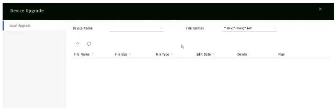
Here you can update the recorder with the latest firmware.
Here you can reset the settings of the recorder, reset the recorder completely to factory settings or set the recorder back to "inactive".
10.4. Logbook
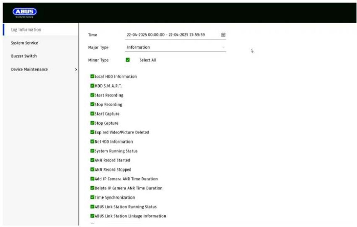
All interactions and events are recorded in the logbook. Entries can be filtered and displayed here according to specific criteria.
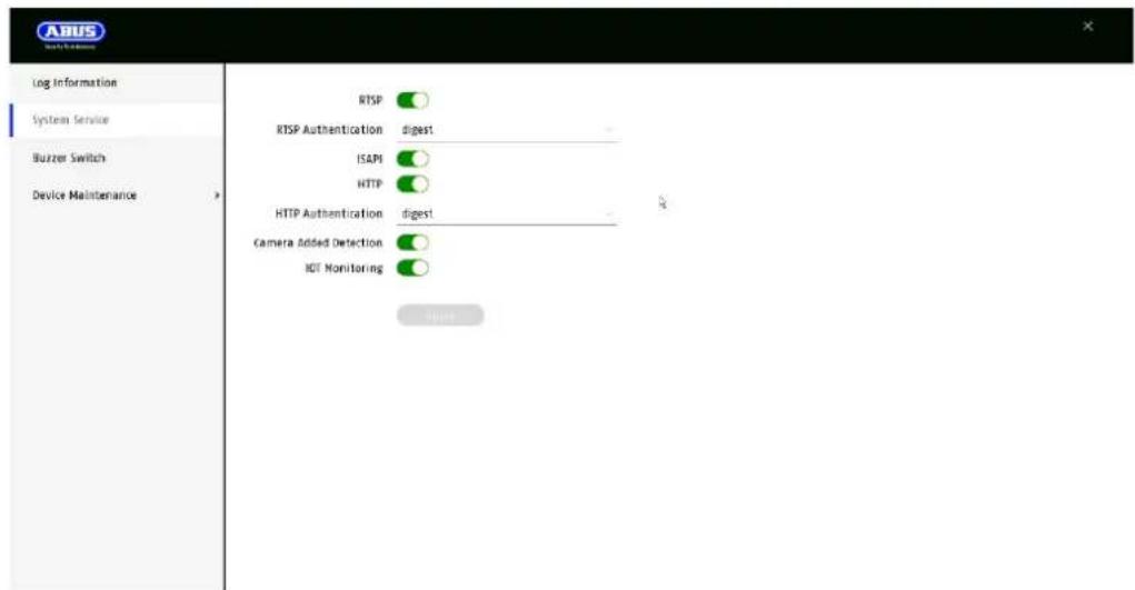
10.5. System maintenance
Various protocol settings can be made in this menu.
11. Maintenance and cleaning
11.1. Maintenance
Regularly check the technical safety of the product, e.g. damage to the housing.
If it can be assumed that safe operation is no longer possible, the product must be taken out of service and secured against unintentional operation.
It can be assumed that safe operation is no longer possible if
• the device shows visible damage,
• the device no longer works

Please note:
The product is maintenance-free for you. There are no components inside the product for you to check or maintain, never open it.
11.2. Cleaning
Clean the product with a clean, dry cloth. For heavier soiling, the cloth can be lightly moistened with lukewarm water.

Make sure that no liquids get into the appliance.
Do not use chemical cleaners, as this could damage the surface of the housing and the screen (discoloration).
12. Waste disposal

Attention: EU Directive 2002/96/EC regulates the proper return, treatment and recycling of used electronic equipment. This symbol means that, in the interests of environmental protection, the appliance must be disposed of at the end of its service life in accordance with the applicable legal regulations and separately from household or commercial waste. The old appliance can be disposed of at official collection points in your country. Follow the local regulations when disposing of the materials. For more details on take-back (also for non-EU countries), please contact your local administration. Separate collection and recycling conserves natural resources and ensures that all regulations for the protection of health and the environment are observed when recycling the product.
13. Technical data
The technical data of the individual cameras is available at www.abus.com via the product search.
14. Open Source license information
We would also like to point out at this point that the network surveillance camera contains open source software, among other things. Please read the open source license information enclosed with the product.
TVVR36302 / TVVR36402
TVVR36702 / TVVR36802
natural_image
Exterior view of a black and silver ASUS audio device (no visible text or symbols on body)Directive RoHS 2011/65/EU
natural_image
Exterior view of a black and white ASUS audio device (no visible text or symbols on body)
Lay-out / Advertenties
natural_image
Exterior view of a black and silver ASUS audio equipment unit (no visible text or symbols on body)
Brugeradministration finder sted i menuen "Brugere".
| Alarmvært-IP | CMS-stationens netværksadresse |
| Alarm-værtsport | Port på din CMS-station(standard: 7200) |
| Serverport | Port til datakommunikation til ABUS CMS og iDVR App / ABUS LINK STATION APP (normal forbindelse via IP)(Standard: 8000) |
| HTTP-port | Port på webserveren(standard: 80) |
| Multicast IP | Du kan også indtaste multicast-IP'en her for at minimere trafikken. IP-adressen skal matche den i videoovervågningssoftwaren. |
| RTSP-port | Angiv RTSP-porten(standard: 554) |
9.2.7 Cloud-adgang / ABUS Link Station

natural_image
Exterior view of a black and silver ASUS audio workstation (no visible text or symbols on body)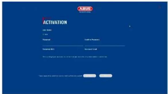
Porta NPT: Attacco NPT
9.2.7 Accesso al cloud / ABUS Link Station

- TVVR36302 / TVVR36402
- TVVR36702 / TVVR36802
- EN Local user interface instructions
- Table of contents
- Declaration of conformity
- Disclaimer
- Explanation of symbols
- Important safety instructions
- Safety instructions
- Warnings
- Unpacking
- Intended use
- Setup wizard
- Live view
- Main menu
- Camera command
- Display menu
- Playback view
- Camera selection
- Calendar
- Camera command
- Playback control
- Time representation Timeline
- Timeline control
- File search
- System settings
- System / General
- System / Live view
- Channel zero
- System / User
- Add user
- Change user
- Delete user
- NTP (Simple mode)
- Exception (simple mode)
- Network
- Note
- TCP/IP
- DDNS
- PPPoE
- NAT
- NTP
- Protocol server setting
- Further settings
- Cloud access / ABUS Link Station
- Camera
- Add IP camera
- Picture (settings)
- Private zone
- Event
- Normal event
- Perimeter protection
- Face recognition
- Intelligent search / people search
- Storage
- Schedule
- Extended
- Stream settings
- Memory
- Add network drive
- Storage mode
- Mode: Contingent
- Advanced settings
- Facial image library
- Maintenance settings
- System info
- Firmware update
- Logbook
- System maintenance
- Maintenance and cleaning
- Maintenance
- Please note:
- Cleaning
- Waste disposal
- Technical data
- Open Source license information
- Lay-out / Advertenties
- Cloud-adgang / ABUS Link Station
- Accesso al cloud / ABUS Link Station
Brand : ABUS
Model : TVVR36302
Category : VCR