
TVVR45030 - VCR ABUS - Free user manual and instructions
Find the device manual for free TVVR45030 ABUS in PDF.
| Product Type | NVR Network Video Recorder |
| Brand | ABUS |
| Model | TVVR45030 |
| Number of Camera Channels | 32 (network cameras) |
| Video Compression | H.264, MPEG-4 |
| Maximum Resolution per Camera | 1920 x 1080p at 25 fps |
| Total Frame Rate | 800 fps |
| Video Outputs | 1 x VGA, 1 x HDMI, 1 x BNC (CVBS) |
| Internal Storage | 8 x SATA HDD (hard drives not included) |
| External Backup | 3 x USB 2.0, 1 x eSATA |
| Audio Inputs | 1 x Line In (RCA, 2.0 Vp-p, 1000 Ω) |
| Audio Outputs | 2 x RCA (600 Ω) |
| Alarm Inputs | 16 (NO/NC) |
| Relay Outputs | 4 (12 V DC / 1 A each) |
| Network | 2 x RJ45 10/100/1000 Mbps, up to 128 simultaneous connections |
| PTZ Control | RS-485, PELCO-D, PELCO-P, Samsung, LG-MULTIX protocols |
| Power Supply | 100-240 V AC, 6.3 A, 47-63 Hz |
| Power Consumption | < 45 W (without hard drive) |
| Dimensions (W x H x D) | 470 x 90 x 45 mm |
| Weight | ≤ 8 kg (without hard drive) |
| Operating Temperature | -10°C to +55°C |
| Interface Languages | German, English, French, Dutch, Danish, Polish, Spanish, Czech |
| Main Functions | Continuous recording, motion detection recording, alarm recording, scheduled recording, playback, event search, export, PTZ control, email notifications, DDNS, NTP |
| Care and Cleaning | Clean with a damp cloth, without solvents. Disconnect before cleaning. Internal maintenance reserved for qualified personnel. |
| Security | Administrator password protection, user management with differentiated rights, secure network access, alert in case of unauthorized connection |
| Spare parts and repairability | Hard drive replaceable by a professional. No spare parts provided; repairs must be carried out by an authorized service. |
| General Information | Compliant with European directives (CE, RoHS, WEEE). Supplied with power cable, SATA cable, screws, rack mount, software CD, manual. |
Frequently Asked Questions - TVVR45030 ABUS
User questions about TVVR45030 ABUS
0 question about this device. Answer the ones you know or ask your own.
Ask a new question about this device
Download the instructions for your VCR in PDF format for free! Find your manual TVVR45030 - ABUS and take your electronic device back in hand. On this page are published all the documents necessary for the use of your device. TVVR45030 by ABUS.
USER MANUAL TVVR45030 ABUS
This user guide contains important information on starting operation and using the device.
Make sure that this user guide is handed over when the product is given to other persons.
Keep this user guide to consult later.
A list of contents with the corresponding page number can be found in the index.
Français
Operating elements on the device 83
Connections on the rear of the device 84
Operating elements on the remote control 86
Mouse operation 86
Quick guide 105
Before you start 105
Installing the HDD 105
Establishing the connections 105
Configuring the device 105
Important safety information 106
Explanation of symbols 106
Proper use 106
General information 106
Power supply 106
Overloading / overvoltage 107
Cables 107
Installation location / operating environment 107
Remote control. 107
Care and maintenance. 108
Accessories 108
Putting into operation 108
Children and the device 108
Introduction 109
General information 109
Unpacking the device 109
Scope of delivery 109
On-screen keyboard 110
Starting the device 110
Switching off, locking and rebooting the device 110
Status displays. 111
General information 111
DVR status LED 111
Camera selection keys - status LED 111
Displays on the monitor 111
Setup wizard 112
Setting up the system 112
Setting up the administrator 112
Time / Date 112
Network Settings 113
HDD Management 114
Setting up network cameras 114
Camera recording 114
Live view 115
Overview 115
Status symbols 115
115
Selection bar in the camera image 116
Settings 117
Setting the camera output 117
Playback 118
General information 118
Playback screen 118
Using the control panel. 118
Right click when playback is running 119
Main menu 120
Menu overview 120
Menu description 120
Menu description 121
Settings - Configuration 122
Overview 122
General 122
Terms and definitions 123
Network layout 124
Network-configuration 124
Live view 130
Warning. 130
User 130
Camera 132
OSD 132
Image 132
PTZ 132
Motion 133
Handling 133
Setting up 135
Schedule 135
Encoding 136
Confirm the settings by clicking Apply and leave the menu with Back. 137
Advanced settings (TVVR45030) 137
Holidays 137
HDDs 138
Installing the HDD 138
HDD Management parameters 138
HDD settings of the cameras 139
Hard disc setting 139
Checking the HDD status 140
Setting up the HDD alarm 140
S.M.A.R.T. 140
Continuous Recording 141
Event 141
Marking 141
Image 141
Maintenance 143
System Info 143
Log Search 143
Import/Export 144
Upgrade 144
Default 145
Network 145
Video Export 147
Duration 147
Event (event type 'Alarm input') 148
Event (event type 'Motion') 148
Manual Management. 149
Record. 149
Continuous Capture 149
Alarm 149
Shutdown 149
Troubleshooting 150
Device cleaning and care 150
Note 150
Technical data 151
Disposal 153
Information on the EU directive on waste electrical and electronic equipment 153
Information on handling batteries 153
Important information on disposing of batteries. 153
Information on the European RoHS directive 153
Glossary 154
Overview of specialist terms 154
Internal HDD 156
Overzicht 160
Firmware Upgrade 222
Standaard 223
Netzwerk 223
Uitschakelen 224
Backup 225
Opnameplannen 225
Evenement (gebeurtenistype „Alarm ingang" ). 226
Evenement (gebeurtenistype „Beweging") 226
Handmatig Management 227
Record 227
Disque management 291
Disque 291
Spcifications techniques 304
Installation of hardisken 319
HnDnkaun Ha MoHTope. 459
Pomouhik Hactpoek 460
HacpoKa cncTeMbI 460
HacrpoKa AdminncTpaTopa 460
CnCTeMHoe Bpemn n daTa 460
Hac troknc cetn 461
YnpabJIeHne JecTKIM DnCKOM 461
Hac troka IP-kanep. 462
3anncb kamepbbl 462
OTo6paKeHne 463
063op 463
CIMBOJI COCTOHN 463
Bcnnbibaiooee MeHIO npu ynpabneHHMblbIO 463
Bklaika Bbl6opa B n3o6paXeHn KaMepbl 464
Hac trokki 465
Hacrpoika BbIXoJa KaMepbl 465
Bocnpon3BeHne B pexnme OTo6paXeHHN 466
Obuie noJoxhen 466
3KpaH Bocnpo3BeJeHn 466
Unpabnene c nomoou naheyn ynpabnene 466
IeJyok npabov KhoNkoMbIu npTekyuem Bocnpou3BeDeHnn. 467
Mehno npnbopa. 468
O63op MeHIO 468
Onicahne MeHIO 468
Hac troponi 469
Onicahne MeHIO 469
KoHpyraua 470
063op 470
OchOBhIe HacTpoiKn 470
Понатя 472
CTyKTypa cetn 473
KoHpfupauncaetn 473
PpeDynpexKeHne 479
Pojlb30BaTeIb 479
Kamepa. 481
OSD 481
I3o6paXeHne 481
PTZ 482
Двженье 482
IeJCTBue 482
Hacrpoika 484
PacnicaHne 484
Koindorobanie 485
YcTaHOBka JeCTKOTo DnCKa 487
IapametpbI ynpabneneHJKeCTKIM DnCKOM 487
HacTpoKa JecTKnx DnCKOB dIy Kamep 488
XecTkni Dnck: HacTpoiKa 488
PpOBepntb cTaTyc JeecTKoro DnCKa 489
Hac trokki TpeBorri JecTkoro Dncka. 489
PpOdoJxHtBnocTb 490
Cobitne 490
RpIbIK 490
I3obpaKeHne 491
Texnueckoe obcnykubache 492
CbeHnO CnCTeme 492
IpoToKoI PoIck 492
Ummopt/ekcnopT 493
OboBJIeHne 494
,Network Time Protokoll'
,Universal Serial Bus'
ABUS 32-channel Network video recorder NVR TVVR45030

User manual
English
These user manual contains important information for installation and operation.
This should be also noted when this product is passed on to a third party.
Therefore look after these operating instructions for future reference!
A list of contents with the corresponding page number can be found in the index.
See System operation on page 83.
Pay attention to the information in the separate quick guide, plus the notes on the CD and in the accompanying documentation on "Web server control" and "Clients Software". These can be found on the Internet under www.abus.com.
Device overview
i See System operation on page 83.
Front
Rearside
System operation
General information
The device can be controlled as follows:
- Using the operating elements on the front of the device
- Using the remote control
- Using the USB mouse
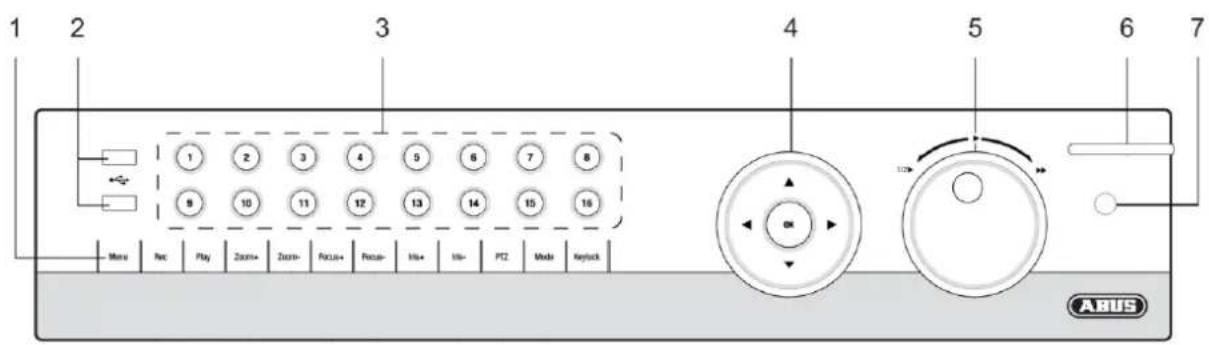
Operating elements on the device
i Note
Pay attention to the overview on page 82.
| No. | Name Function |
| 1 | Recorder operating keys: MENU: • Calls up the main menu • Switches the key tones on and off (press and hold down for 5 seconds) REC: • Calls up the menu for manual recording PLAY: • Opens the playback menu ZOOM+: • Zooms in on the image section in PTZ mode ZOOM-: • Zooms out of the image section in PTZ mode • Switches the video output in live mode: Moni- tor - Spot Monitor or Video Out - Video Spot Out FOCUS+: • Sets the focus in PTZ mode FOCUS-: • Sets the focus in PTZ mode IRIS+: • Opens the iris IRIS-: • Closes the iris in PTZ mode PTZ: • Activates the PTZ control MODE: • Switches the screen view KEYLOCK: • Locks the control keys |
| 2 | USB ports: For external USB 2.0 devices (e.g. mouse, ex- ternal disk drive or DVR burner) |
| No. | Name Function |
| 3 | Camera selection keys (1, 2, 3...): Displays the camera status: • White: Camera is connected • Blue: Connected camera is recording • Not lit: No camera connected In the live view: • Selects the camera and displays the full-screen view |
| 4 | Directional keypad: During playback: • ▲, ▼ Sets the speed • ←, ▷ Previous / next day In the live view: • Selects the channel In menus: • Navigation OK key: • Press and hold for 5 seconds to switch the device on and off • Confirms the selection • Ticks / unticks the boxes During playback: • PLAY/PAUSE Increased/ decreased playback speed: • Normal playback speed |
| 5 | Jog Shuttle: During playback: • Outer ring (shuttle ring) change playback speed • Inner ring to play single frames in single mode In menus: • Inner ring moves the cursor upwards / downwards • Outer ring moves the cursor left / right In the live view: • Selects the channel |
| 6 | NVR status LED: Displays the device status: • White (constantly lit): System status is OK • White (flashing): System status is OK, recording settings are stored, surveillance mode is active • Blue (constantly lit): At least one camera is currently recording • Red (constantly lit): System maintenance required |
| 7 | IR receiver: For the remote control |
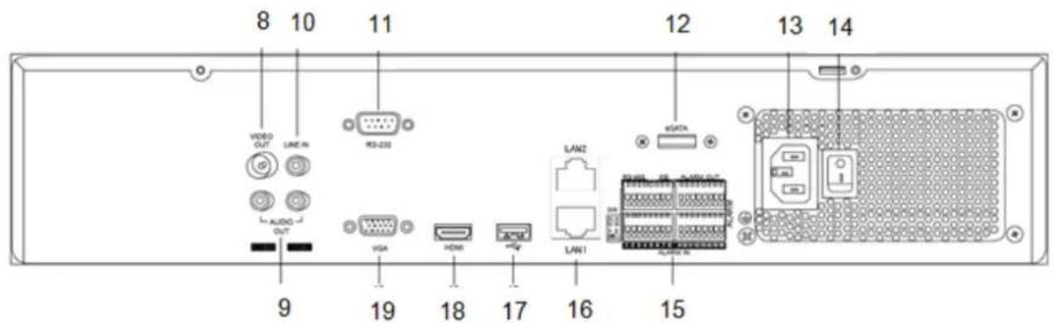
Connections on the rear of the device

Note
Pay attention to the overview on page 82.
19
VGA:
VGA monitor connection (9-pin), video output signal
| No. | Name Function |
| 8 | VIDEO OUT: BNC video output BNC connector for video output for connecting a monitor as an alternative to VGA-/HDMI output (no. 18 / no. 19) |
| 9 | AUDIO OUT: • (TVVR45030) cinch audio output (synchronised with video output) |
| 10 | LINE IN: • Cinch audio input (TVVR45030) (is not recorded, only transmitted via network) |
| 11 | RS-232: • Serial port – no functionality |
| 12 | eSATA connection (TVVR45030) • Serial connection for external SATA hard disk drive |
| 13 | Mains power connection: • 100-240 VAC, 50-60 Hz |
| 14 | Power switch |
| 15 | ALARM IN: • RS485 connection for PTZ cameras • Max. 16 alarm inputs ALARM OUT: • Max. 4 relay outputs |
| 16 | LAN: • 2x Ethernet LAN connection |
| 17 | USB: • USB Connector |
| 18 | HDMI: • HDMI monitor connection |
Remote control (TVAC40930)
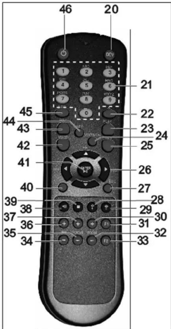
Operating elements on the remote control

Note
Pay attention to the remote control diagram on page 67.
| No. | Name Function |
| 20 | DEV: Assigns the remote control with the device ID |
| 21 | Alphanumeric keys: • Selects the camera (channel) in the live view • Entry of letters and digits in system fields |
| 22 | A: Changes the entry format (upper / lower case, symbols, digits) |
| 23 | PLAY: Starts playback |
| 24 | VOIP: • Not used |
| 25 | PREV: Changes the screen display in the live view |
| 26 | Navigation keys: During playback: • ▲, ▼ Sets the speed • ←, > Previous / next day In the live view: • Selects the camera (channel selection) In menus: • Navigation |
| 27 | ESC: • Not used |
| No. | Name Function |
| 28 | Not used |
| 29 | Not used |
| 30 | Zoom+: Zooms in on the image section in PTZ mode |
| 31 | F1: In lists: • Selects all available options |
| 32 | Zoom -: Zooms out of the image section in PTZ mode |
| 33 | F2: Switches between tabs |
| 34 | IRIS-: In PTZ mode: • Closes the iris |
| 35 | Focus-: In PTZ mode: • Brings the image section into focus |
| 36 | IRIS+: In PTZ mode: • Opens the iris |
| 37 | Focus+: In PTZ mode: • Brings the image section into focus |
| 38 | II: Pause / reverse playback |
| 39 | ■: Stops playback |
| 40 | PTZ: Switches on PTZ control |
| 41 | Enter II: • Confirms the selection • Ticks / unticks the boxes During playback: • PLAY/PAUSE Single play mode: • Advances by a single frame |
| 42 | MENU: • Calls up the main menu • Switches the key tones on and off (press and hold down for 5 seconds) |
| 43 | REC: Opens / starts manual recording |
| 44 | INFO: • Switches to another monitor in the live view |
| 45 | EDIT: General use: • Activates the text entry; backspace in text fields |
| 46 | POWER: Switches on/off (hold down for 5 seconds) |
Mouse operation

Note
Further descriptions in these operating instructions are made with the mouse.
The device is suitable for use with a USB mouse. Connect the mouse to the USB port.
| Button | Function |
| Left | Single-click:Selection in menu, activation of an entry field or tabDouble-click:Switches between the screen display of single and multiple images in the live view and during playbackClick and drag:In PTZ mode: Camera controlSet-up of alarm areas or zones |
| Right | Single-click:Calls up the pop-up menu |
| Scroll wheel | In the live view:Shows previous / next cameraIn menus:Scrolls through the menus |
Geräteübersicht 3
Systembedienung 4
Allgemeines 4
Bedienelemente am Gerat 4
Operating elements on the device 83
Connections on the rear of the device 84
Operating elements on the remote control 86
Mouse operation 86
Quick guide. 105
Before you start. 105
Installing the HDD 105
Establishing the connections 105
Configuring the device 105
Important safety information 106
Explanation of symbols 106
Proper use 106
General information 106
Power supply 106
Overloading / overvoltage 107
Cables 107
Installation location / operating environment 107
Remote control. 107
Care and maintenance. 108
Accessories 108
Putting into operation 108
Children and the device 108
Introduction 109
General information 109
Unpacking the device. 109
Scope of delivery 109
On-screen keyboard 110
Starting the device 110
Switching off, locking and rebooting the device 110
Status displays 111
General information 111
DVR status LED 111
Camera selection keys - status LED 111
Displays on the monitor 111
Setup wizard 112
Setting up the system 112
Setting up the administrator 112
Time / Date 112
Network Settings 113
HDD Management 114
Setting up network cameras 114
Camera recording 114
Live view 115
Overview 115
Status symbols 115
115
Selection bar in the camera image 116
Settings 117
Setting the camera output 117
Playback 118
General information 118
Playback screen 118
Using the control panel. 118
Right click when playback is running 119
Main menu 120
Menu overview 120
Menu description 120
Menu description 121
Settings - Configuration 122
Overview 122
General 122
Terms and definitions 123
Network layout 124
Network-configuration 124
Live view 130
Warning. 130
User 130
Camera 132
OSD 132
Image 132
PTZ 132
Motion 133
Handling 133
Setting up 135
Schedule 135
Encoding 136
Confirm the settings by clicking Apply and leave the menu with Back. 137
Advanced settings (TVVR45030) 137
Holidays 137
HDDs 138
Installing the HDD 138
HDD Management parameters 138
HDD settings of the cameras 139
Hard disc setting 139
Checking the HDD status 140
Setting up the HDD alarm 140
S.M.A.R.T. 140
Continuous Recording 141
Event 141
Marking 141
Image 141
Maintenance 143
System Info 143
Log Search 143
Import/Export 144
Upgrade 144
Default 145
Network 145
Video Export 147
Duration 147
Event (event type 'Alarm input') 148
Event (event type 'Motion') 148
Manual Management 149
Record 149
Continuous Capture 149
Alarm 149
Shutdown 149
Troubleshooting 150
Device cleaning and care 150
Note 150
Technical data 151
Disposal 153
Information on the EU directive on waste electrical and electronic equipment 153
Information on handling batteries 153
Important information on disposing of batteries. 153
Information on the European RoHS directive 153
Glossary 154
Overview of specialist terms 154
Internal HDD 156
Overzicht 160
Bediening van het systeme 161
Algemeen 161
Bedieningselementen op de recorder 161
Contents
Firmware Upgrade 222
Standaard 223
Netzwerk 223
Uitschakelen 224
Backup 225
Opnameplannen 225
Evenement (gebeurtenistype „Alarm ingang" ). 226
Evenement (gebeurtenistype „Beweging") 226
Handmatig Management 227
Record 227
Contents
Disque management 291
Disque 291
Spcifications techniques 304
Installation of hardisken 319
Udforelse at Standard 362
Netvark 362
Video Export 364
Normal 364
Haendelse (haendelsestype ,Alarmindgang) 365
Haendelse (haendelsestype,Bevgelsesregistering) 365
Panikoptagelse 366
Optagelse 366
KJIaBnBbIbopaKaMepbCBeToOnObcOCToHnA 459
INHnkaaHa MoHTope. 459
Pomouhik Hactpoek 460
Hac troika cnctembl 460
Hactpoika AdmnnctpaTopa 460
CnCTeMHoe Bpemn I daTa 460
Hac troknc cetu. 461
YnpabJIeHne XecTKIM DnCKOM 461
Hac trokka IP-kanep. 462
3anncb kamepbbl 462
OTo6paKeHne 463
063op 463
CIMBOJI COCTOHN 463
Bcnpbibaiooee MeHIO npu ynpabneHHMblb. 463
BklaKa Bb6opa B n3o6paXeHn KaMepbl. 464
Hac trojkn 465
HacrpoKa BbIXoJa KaMepbl 465
Bocnpon3BeJeHne B peXnme OTo6paXeHnra 466
Obuie noJoxhen 466
3KpaH Bocnpou3BedeHn 466
Unpablenne c nomoou npaneu ynpablennna 466
IeKpO KHOKoMbI npTeKUcem BocnpOn3BeDeHn. 467
Mehno npnbopa. 468
O63op MeHIO 468
Onicahne MeHIO 468
Hac troponi 469
Onicahne MeHIO 469
KoNΦnrgpaun. 470
063op 470
OchOBhIe HacTpoiKn 470
Понатя 472
CTyKtypacetn 473
KoHpUpaua cTei 473
Ipeunppexdene 479
Tolb30BateIb 479
Kamepa. 481
OSD 481
I3o6paXeHne 481
PTZ 482
Двженье 482
Дeйства 482
Hacrpoika 484
PacnicaHne 484
Koindropobanie 485
Дононтульные установки (Toько TVVR45030) 485
MeHIO «OTnyck» 486
KecTKne DnCKn 487
YcTaHOBka JeecTKoro DnCKa 487
IapametpyynpabBneHnJxecTKM DnCKOM 487
Hacrpoika JecTKnx DnCKOB dIy Kamep 488
KecTkni Dnck: HacTpoiKa 488
PpOBepntb cTaTyc JeecTKoro DnCKa 489
Hactpoyn TpeBorn JecTKoro Dncka 489
PpOdoJxHtBnocTb 490
Cobitne 490
Ярльik 490
I3obpaKeHne 491
Texnueckoe obcnykubache 492
CbeHnO CnCTeme 492
IpoToKoJ POnsck 492
UmmopT/ekcnopT 493
OboBJIeHne 494
Ppoun3BecTu BocCTaHOBJIeHne CnCTeMbI 495
Cetb 495
Pe3epB.Konna 497
PpOdoJxHcTbHocTb 497
Co6bItne (TIN co6bITnA «TpeBOKHbI BxOaD) 498
Co6bItne (TIN co6bITnRA "TpeBxHbI BxOa") 498
499
3a\Pncb BpyHnyu 499
IpoJIoJx.3axBaT 499
Tpebora 499
3aBepueHne pa6oTbI 500
Hdkaia 500
HacrpoKn:3aIncb 500
HacrpoKn:PTZ 500
HacTroPouKn: Cetb. 500
Contents
HacrpoKn: CngnaIinaia 500
HacrpoKn: RS232 500
UcTpaHHe HEnCnpaBHOCTeI 501
OuicKa ycTpoiCTBa n yxod 501
Yka3aHne 501
Texnueckne xapaKTepeNcTnKn 502
ytnn3a.. 504
CcbIka Ha dIpeKTHBy EC no yTnJIn3aun CTaporo 3JeKtpueckoro n 3JeKtpoHoro o6OpydoBaHna. 504
Uka3aHnno o6paueHHc 6aTapeMa.. .504
Baxhna nHopmaun no ytnn3aun 6aTapei.. .504
CcbIka Ha dupeKTHBy EC RoHS. 504
Tnoccapni 505
IcnoJIb3yeMbIe TepMnHbl 505
OBHyTpHHeM XecTkom DnCke 507
Quick guide
Before you start
The following preparatory steps must be made:
- Pay attention to the general information, safety information and notes on setting up and connecting the device (see page 83).
- Check the contents of the package for completeness and damages.
- Insert the batteries into the remote control.

Note
Pay attention to the information in the separate quick guide.
Installing the HDD

Warning
Switch off the device and disconnect it from the mains power supply.
Pay attention to the required earthing of the device to avoid static discharge.
- Install one or more HDDs (see the separate quick guide).
- Firstly, establish the connection to the motherboard using the red data cable (small connector).
- Connect the power supply cable (large 5-pin connector).
- Check that the connections are secure.
- Close the housing.

Note
Only use HDD's that are approved for video recording and 24/7 usage.
Establishing the connections

Note
Pay attention to the minimum radius when laying cables. Do not kink the cable.
- Connect all network cameras with your network
- Connect the audio connections.
- Connect the sensors to the alarm inputs.
- Connect the monitor to the HDMI/VGA or BNC connection.
- Connect the mouse to the USB port.
- Establish a connection to the mains power supply.
- Switch on the device using the POWER switch on the rear. The DVR status display on the front of the device lights up.
Configuring the device

Note
Pay attention to the information in the separate quick guide.
- Proceed through the individual steps in the setup wizard (see page 112).
The following settings are configured in sequence:
- Language selection for the user interface
- Administrator setup
- General settings (date, time etc.)
HDD management (initialisation etc.)
Network settings - Camera management

Note
Subsequent changes to the date and time can lead to the loss of data!

Note
Check the ABUS homepage (www.abus.com) if for this device any firmware updates are available and install these
- Pay attention to the menu overview on page 120, plus the notes and explanations on basic system operation on page.
Pay attention to the notes on the following:
| Live view | Page 115 |
| Playback | Page 112 |
| PTZ | Page 132 |
| Export | Page 143 |
| Troubleshooting | Page 150 |
Important safety information
Explanation of symbols
The following symbols are used in this manual and on the device:
Symbol
Signal word Meaning

Warning Indicates a risk of injury or health hazards.

Warning Indicates a risk of injury or health hazards caused by electrical voltage.

Important Indicates possible damage to the device/accessories.
Note Indicates important information.
The following labels are used in the text:
| Meaning | |
| 1. ... | Set of tasks or instructions with a defined sequence in the text |
| 2. ... | |
| • ... | Set of points or warnings without a defined sequence in the text |
| • ... |
Proper use
Only use the device for the purpose which it was designed and built for. Any other use is considered inappropriate.
This device may only be used for the following purpose(s):
- This NVR recorder is used in combination with connected video signal sources (network cameras) and video output devices (CRT or TFT monitors) for object surveillance.

Note
Data storage is subject to national data-protection guidelines.
During installation, inform your customers regarding the existence of these guidelines.
General information
Before using the device for the first time, read the following instructions carefully and pay attention to all warnings, even if you are already familiar with electronic devices.

Warning
All guarantee claims become invalid for damages caused by non-compliance with these operating instructions.
We cannot be held liable for resulting damages.

Warning
We cannot be held liable in the event of material or personal damage caused by improper operation or non-compliance with the safety information.
All guarantee claims are invalid in such cases.
Keep this manual in a safe place for future reference.
If you pass on or sell the device, you must also include this user manual.
This device has been manufactured in accordance with international safety standards.
Power supply
- Only operate this device through a power source which supplies the mains power specified on the type plate.
- If you are unsure of the power supply at the installation location, contact your power supply company.

Warning
Avoid data loss!
Always use an uninterruptible power supply (UPS) with overvoltage protection.
- Disconnect the device from the mains power supply before carrying out maintenance or installation work.
- The on/off switch does not completely disconnect the device from the mains power supply.
- To disconnect the device completely from the mains power supply, the plug must be disconnected from the mains socket. Therefore, the device should be positioned so that direct and unobstructed access to the mains socket is guaranteed at all times and the plug can be disconnected immediately in an emergency.
To avoid the possibility of fires, the plug should always be disconnected from the network socket if the device is not used for long periods. Disconnect the device from the mains power supply before impending electrical storms, or use an uninterruptible power supply.

Warning
Never open the device on your own! There is a risk of electric shocks!
If it is necessary to open the device, consult trained personnel or your local maintenance specialist.
- The installation or modification of a HDD should only be made by trained personnel or your local maintenance specialist.

Warning
The installation of additional equipment or modification of the device invalidates your guarantee if not carried out by trained personnel.
We recommend having the HDD installed by a maintenance specialist.
Your guarantee is invalidated in the event of improper installation of the HDD.
Overloading / overvoltage
- Avoid overloading of mains sockets, extension cables and adapters as this can result in fires or electric shocks.
- Use overvoltage protection to prevent damages caused by overvoltage (e.g. electrical storms).
Cables
- Always hold cables by the connector, and do not pull the cable itself.
- Never touch the mains cable with wet hands, as this can lead to a short circuit or electric shock.
- Never position the device, furniture or other heavy items on the cable. Ensure that the cable does not become kinked, especially on the connector and sockets.
- Never knot the cable, and do not tie it to other cables.
- All cables should be laid so that they cannot be stepped on or cause an obstruction.
- A damaged mains cable can cause a fire or electric shock. Check the mains cable from time to time.
- Never modify or manipulate the mains cable or plug.
- Do not use plug adapters or extension cables that do not conform to the applicable safety standards, and do not make alterations to power supply cables or mains cables.
Installation location / operating environment
- Position the device on a firm, level surface and do not place any heavy objects on the device.
- The device is not designed for operation in rooms subject to high temperatures or moisture (e.g. bathrooms), or in excessively dusty rooms.
- Operating temperature and ambient humidity: -10 °C to 55 °C, maximum 85% relative humidity. The device may only be operated in moderate climate conditions.
Ensure the following:
- Sufficient ventilation must be present at all times (do not place the device in a storage rack, on thick carpets, on a bed or anywhere where the ventilation slots are covered. Make sure that a gap of at least 10cm is present on all sides).
- The device must not be exposed to direct heat sources (e.g. heaters).
- The device must not be exposed to direct sunlight or strong artificial light.
- The device must not be placed in close proximity to magnetic fields (e.g. loudspeakers).
- Naked flames (e.g. candles) must not be placed on or near the device.
- Contact with spraying or dripping water and aggressive liquids must be avoided.
- The device must not be operated in close proximity to water, and must not be submerged under any circumstances (do not place objects containing water on or near the device, such as vases or drinks).
Foreign objects must not penetrate the device. - The device must not be exposed to strong variations in temperature, as this can lead to condensation and electrical short circuits.
- The device must not be exposed to excessive jolts or vibrations.
Remote control
- Remove all batteries if the device will not be used for a sustained period, as these can leak and damage the device.
Care and maintenance
Maintenance is necessary if the device has been damaged. This includes damage to the plug, mains cable and housing, penetration of the interior by liquids or foreign objects, exposure to rain or moisture or when the device does not work properly or has fallen.
- Disconnect the device from the mains power supply before maintenance (e.g. cleaning).
- If smoke develops or unusual noises or odours are detected, then switch off the device immediately and pull the mains plug from the socket. In such cases, the device should not be used until it has been inspected by a qualified technician.
- Maintenance work should only be carried out by qualified specialists.
- Never open the housing on the device or accessories. There is a risk of fatal injury due to an electric shock when the housing is opened.
- Clean the device housing and remote control with a damp cloth.
- Do not use solvents, white spirit or thinners as these can damage the surface of the device.
- Do not use any of the following substances:
Salt water, insecticides, solvents containing chlorine or acids (ammonium chloride) or scouring powder. - Gently rub the surface with a cotton cloth until it is completely dry.

Warning
The device works under dangerous voltages. The device must only be opened by authorised spec-. cialists. All maintenance and service work must be carried out by authorised firms. Improper repairs can expose device users to the risk of fatal injury.
Accessories
- Only connect devices that are suitable for the intended purpose. Otherwise, hazardous situations or damage to the device can occur.
Putting into operation
- Observe all safety and operating instructions before putting the device into operation for the first time.
- Only open the housing to install the HDD.

Warning
When installing the device in an existing video surveillance system, ensure that all devices are disconnected from the mains power supply and low-voltage circuit.

Warning
If in doubt, have a specialist technician carry out assembly, installation and connection of the device.
Improper or unprofessional work on the mains power supply or domestic installation puts both you and other persons at risk.
Connect the installations so that the mains power circuit and low-voltage circuit always run separately from each other. They should not be connected at any point or become connected as a result of a malfunction.
Children and the device
- Do not allow children access to electrical devices. Never allow children to use electrical devices without supervision. Children may not be able to accurately detect possible risks. Small parts can be life-threatening if swallowed.
- Keep batteries away from small children. Call for medical assistance immediately if a battery is swallowed.
- Keep packaging materials away from children (danger of suffocation).
- This device should not be used by children. If used improperly, spring-loaded parts can be ejected and cause injuries to children (e.g. eye injuries).
Introduction
Dear customers,
Thank you for purchasing this product.
This product complies with current domestic and European regulations. Conformity has been proven, and all related certifications are available from the manufacturer on request (www.abus.com).
To maintain this status and to guarantee safe operation, it is your obligation to observe these operating instructions!
Read the entire operating manual carefully before putting the product into operation and pay attention to all operating and safety information!
All company names and product descriptions are trademarks of the corresponding owner. All rights reserved.
In the event of questions, please contact your local maintenance specialist or dealer.

Disclaimer
These operating instructions have been produced with the greatest care. Should you discover any missing information or inaccuracies, please contact us under the address shown on the back of the manual. ABUS Security-Center GmbH does not accept any liability for technical and typographical errors, and reserves the right to make changes to the product and operating instructions at any time and without prior warning. ABUS Security-Center GmbH is not liable or responsible for direct or indirect damages resulting from the equipment, performance and use of this product. No forms of guarantee are accepted for the contents of this document.
General information
In order to use the device correctly, read this user manual carefully and keep it in a safe place for later use.
This manual contains instructions on recorder operation and maintenance. Consult an authorised specialist if the device needs to be repaired.
Unpacking the device
Handle the device with extreme care when unpacking it.
The packaging is made of reusable materials, and should always be passed on for recycling.
We recommend the following:
Paper, plastic packaging, cardboard and corrugated cardboard should be disposed of in the appropriate recycling containers.
If recycling containers are not available in your local area, then you can dispose of these materials as domestic waste.
If the original packaging has been damaged, inspect the device. If the device shows signs of damage, then return it in the original packaging and contact the manufacturer.
Scope of delivery
- ABUS 16 channel NVR
- Mains cable
- SATA cable and screws for HDD
- Bracket and screws for server racks
- Software CD
- User manual (On CD or enclosed)
- Quickguide (On CD or enclosed)
- Terminal connectors
On-screen keyboard
The on-screen keyboard appears after clicking on a text entry field with the mouse:

The following screen keyboard appears during mere numerical entry:

The keys have the same function as on a computer keyboard.
To enter the character, left-click the mouse.
- To finish data entry, press Enter.
To delete the character in front of the cursor, click on
- To switch between upper and lower case, click on the framed a symbol. The current setting is displayed above the keyboard.
- To cancel the entry or exit the field, press ESC.
Starting the device

Important
The device must only be operated with the mains power specified on the type plate.
For safety reasons, use an uninterrupted power supply (UPS).
After the device has been connected to the power supply and the main switch on the rear of the device is switched on, the DVR status LED lights up.
- The device carries out a self-test during the start-up procedure.
- The setup wizard appears. Exit the wizard to access the live view.
Switching off, locking and rebooting the device
Click on "Shutdown" in the main menu. The overview appears.
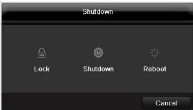
- To switch off the device, select Shutdown and confirm by pressing Yes. The device is then switched off.
- Do not press any keys during the shutdown procedure.
- To lock the system, select the corresponding Lock symbol on the left. The user interface is now locked and a password must be entered to access the menu.
- To reboot the device, select the corresponding Boot symbol on the right. The device is then rebooted.
Switching on the device
- Press and hold the OK key for 5 seconds to switch the device back on.
Status displays
General information
The following status displays indicate the current operating state:
- LEDs on the front of the device
- Acoustic signal tones
- Icons (display elements) on the monitor
Note
Pay attention to the information in the separate quick guide.
DVR status LED
| State | Function |
| White (constantly lit): | System status is OK |
| White (flashing): | System status is OK, recording settings are stored, surveillance mode is active |
| Blue (constantly lit): | At least one camera is currently recording |
| Red (constantly lit): | System maintenance required |
Camera selection keys - status LED
| State | Function |
| Off: | No camera connected |
| White (constantly lit): | Camera is connected |
| Blue (constantly lit): | Camera is currently recording |
Displays on the monitor
The device shows the date and time, camera name and whether a recording is in progress.
- Continuous recording: Blue "R"
- Alarm recording: Red "R"
- Motion recording: Yellow "R"
Setup wizard
Setting up the system
The setup wizard guides you through the necessary basic system settings. The DVR is then set up for recording and surveillance.

Note
All detailed settings can be found in the device menu (see overview on 120).
The language selection appears after switching on for the first time:
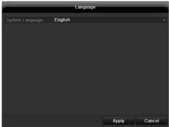
- Click the entry field and select the desired language from the list. Click on Apply to continue. The following query appears:
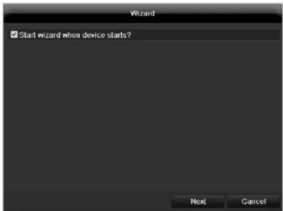
- Click on Next to start the wizard.

Note
After the system is set up, you can untick the box. The setup wizard is then no longer started automatically.
Setting up the administrator

Warning
Note down the admin password. The following password is preset
"12345"

- Click the entry field and enter your admin password.
- To assign a new password, tick the box next to New Admin Password.
- Enter the new password and confirm in the field below.
- Click on Next.
Time / Date
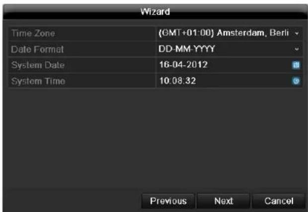
Enter the system time (date and time). Click on Next to accept the data.
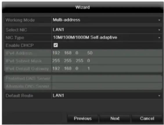
Network Settings

Note
To check whether DHCP can be selected (or if you have to set the IP address and other settings manually), consult your network administrator.
- DHCP activated: If DHCP is set up in the network router, then tick the DHCP box. All network settings are then made automatically.
- DHCP not activated: Enter the data manually (IPv4 address, IPv4 subnet mask and IPv4default gateway = IPv4 address of the router). You can also optionally enter the address of the DNS server that you need for sending the E-mail.
A typical address specification is as follows:
IPv4 address: 192.168.0.50
IPv4 Subnet mask: 255.255.255.0
IPv4 Default gateway: 192.168.0.1
- Preferred DNS server: 192.168.0.1

Note
When the device is accessed remotely via the internet, it should be given a fixed network address.

Note
If you have selected the "multi-address" mode, then you must configure both network connections. For this, change the LAN output at "select NIC".
- Because this device has two network connections, there are setting possibilities for the parallel and the separate use of the connections:
| Net Fault-tolerance | A LAN connection is selected for the data transfer (select "NIC"). The other connection is in a type of standby mode. If ,for whatever reason, data transfer can no longer be guaranteed (e.g. broken network card, defective cable...), change the device to the other interface and use this for data transfer. |
| Load Balance | When this mode is selected, both network cards/network connections work together in order to get a broader band width. |
| Multi-adresse | When selecting this mode, configure the network data separately for each connection. In this way it is possible to integrate the device into two different networks, so that the network load is reduced. |
HDD Management
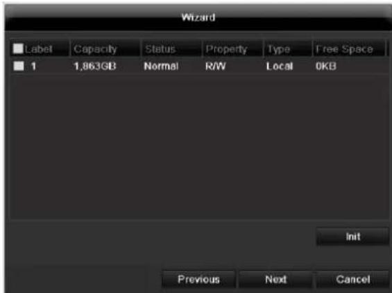
- To set up a new hard disc, activate the "Check box" with a left click and then click on Init.

Warning
All data on the drive is deleted!
- Confirm the prompt by pressing OK. The HDD is then set up for operation. The progress is displayed on the status bar.
- Exit the setting by pressing Next.
Setting up network cameras
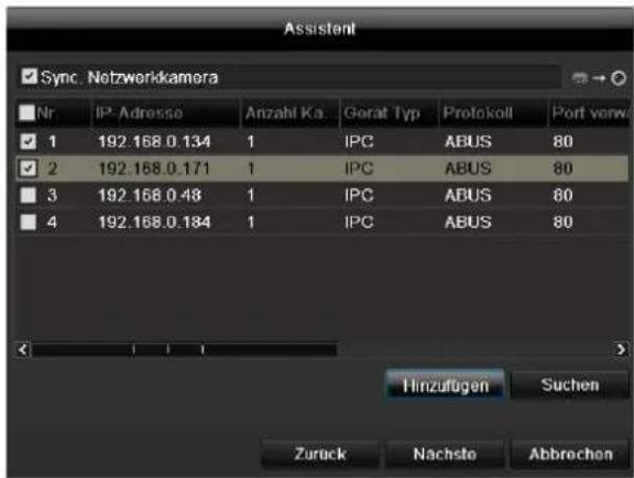
- To setup network cameras, click on Search.
- You can find an overview of all the network cameras found below.
- Activate the "Checkbox" with a left-click to select the network camera and then click on Add.
- Click on Next
Camera recording
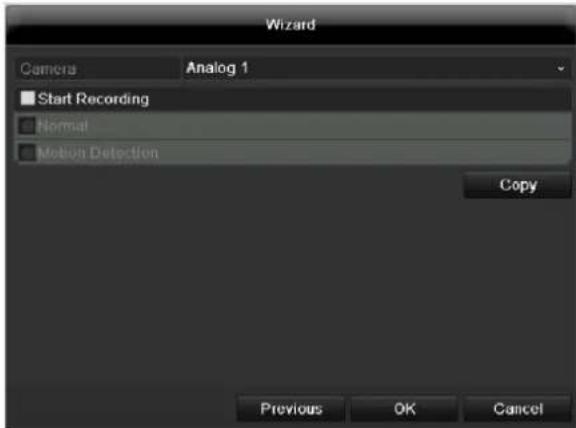
- At "Camera" select a camera with which you would like to record.
- Activate the check box "Start recording".
- Select the type of recording. You can choose between "Time plan" and "Motion recognition". Arm the motion detection inside the camera for recording motion.
- Press Copy to take on the setting for other cameras. For this, select the cameras that appear in the new window. Activate the respective check box with a mouse click.
- Finalize the setting and end the installation assistant with OK.
Live view
Overview
The live view starts automatically after the device is switched on.
You can also go back to the live view by pressing the Menu key repeatedly.

The following menus are found in the screen header:
- Menu
- Playback
- PTZ
The view pop-up menu is found on the right. The time and date are displayed on the right.
- To open the view pop-up menu, click on the rectangular symbol at the top-right of the menu bar.
- Click on one of the symbols to switch between the different views.


The signals of the connected cameras are displayed on the main screen.
- By double-clicking the left mouse key, you can display the camera image as a full-screen view or switch back to the original view.
Status symbols
- The following symbols are displayed depending on the operating status of the device:
| Symbol | Meaning |
| R | Red: Event Recording • Event recording |
| R | Yellow: Motion Recording • Recording at motion detection |
| R | Blue: Recording • Continuous recording |
Pop-up menu for mouse operation

Note
Press the right mouse button when the cursor is positioned on a live image.
The following settings can be made. The arrow pointing to the right indicates that a sub-menu is opened for selection:
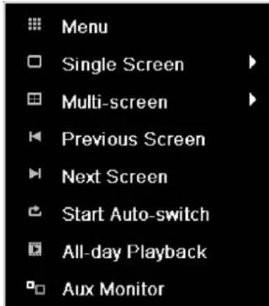
| Menu | Opens the main menu |
| Single Screen | Full-screen view for selected camera |
| Multi Screen | Various camera layouts |
| Previous Screen | Changing the presentation of the previous camera |
| Next Screen | Displays the next camera(s) |
| Start Auto-Switch | Starts the camera sequence |
| All-day Playback | Switches to playback mode |
| Aux Monitor | to spot monitor |
| i | Note Stop Auto-switch: Specify the delay in the image sequence in the display settings. |
| i | Note Activation of “AUX monitor” without a connected spot monitor: Mouse pointer function is deactivated. |
Selection bar in the camera image
Click on the camera image in single or multi view. A selection bar appears:

| № | Meaning of symbol |
| (1) | Area to move the miniature bar |
| (2) | Activate / deactivate manual recording |
| (3) | Immediate playback of the last 5 minutes |
| (4) | Activate / deactivate audio output of video output |
| (5) | Immediate image of selected channel |
| (6) | PTZ-control |
| (7) | digital zoom |
| (8) | Leaving the selection bar |
Settings

Note
The live view can be set as follows.
Open the main menu, then click on "Configuration". Then click on "Liveview":
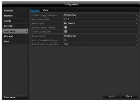
The following settings are available in the TAB "General":
| Video Output Interface | VGA/HDMI, Main CVBS Select the connection where the set-tings are changed |
| Live View Mode | Different camera layouts |
| Dwell Time | Switching time between the individ-ual cameras and the sequence dis-play |
| Enable Audio Output | Activate/deactivate audio output of the video output The audio signal is only given if the corresponding cam-era input is presented as a full screen. |
| Event Output | Allocate monitor for the output of events |
| Full Screen Moni-toring Duration | in seconds, where the event on the allocated monitor will be displayed. |
| Post Event Dis-play Time | in seconds, the duration of the Pop-up window when an event occurs. |

Note
The recorder image can either be shown on an HDMI or a VGA monitor. The combination of HDMI and VGA output is supported.
The BNC output can be used either for a spot monitor or a separate monitor.

Note
VGA monitor connected:
A connected HDMI/VGA monitor automatically becomes the main monitor where the audio output is also assigned. The BNC output Video Spot Out output displays the cameras in sequence and in full screen.
If during the boot process of the DVR the HDMI/ VGA cable is not connected, the main video signal is displayed at BNC out
put MAIN. Connect the HDMI/VGA cable and reboot the DVR in order to display the main video signal at the VGA output.
No HDMI/VGA monitor connected: The main video signal is displayed at BNC output MAIN. The BNC output Video Spot Out output displays the cameras in sequence and in full screen.
Setting the camera output
You can display a maximum of 16 cameras (TVVR45030) in the live cast at the same time.
- Click on the TAB "View".
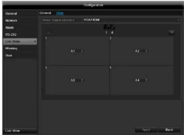
- Select the display mode.
1x1
2× 2
-3x3
1+5
1+7
4× 4
-
The camera signal is assigned to the corresponding image section using the navigation keys.
-
"X" means that this camera is not displayed.
-
Click on Apply to accept the settings.
Playback
General information
Playback can be made in three different ways:
- Through the video search in the main menu
From the live view - Through the log file in the maintenance menu

Note
The buttons "previous file/day/event" are used differently depending on the playback mode:
Normal playback:
By pressing the button the playback jumps to the previous/next day.
Video Search:
By pressing the button the playback jumps to the previous/next event day.
Video Export:
By pressing the button the playback jumps to the previous/next file.

Note
It is possible to start a simultaneous playback with up to 4/8 cameras.
Playback screen
Playback is controlled on the control panel:
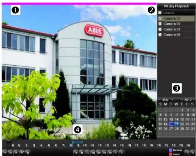
| No. | Area |
| 1 | Running playback with date and time |
| 2 | Used to select the camera for feedback |
| 3 | Calendar with recording type |
| 4 | Control panel with time bar (see right) |
Using the control panel
The control panel (4) is used for controlling the running playback. The symbols have the following meaning:
| No. | Meaning / function |
| 1 | Zoom in / Zoom out the time line (24/12/1 hours) |
| 2 | Audio playback switch on/ off |
| 3 | Define start point / end point of a video for secur-ing data |
| 4 | Add marking |
| 5 | Add user-defined marking |
| 6 | Administrator marking |
| 7 | Backwards playback |
| 8 | Stop |
| 9 | Playback start / pause |
| 10 | Jump backward 30 seconds |
| 11 | Jump forward 30 seconds |
| 12 | Slow forward (slow motion) (1/16x - 1x) |
| 13 | Fast forward (1x - 16x) |
| 14 | Previous recording, previous day |
| 15 | Next file/day/event |
| 16 | Time bar:Click on the time bar with the mouse to con- tinue playback from another pointTo start playback from a specific time, click on the slider and drag it to the required time |
| 17 | Recording typeBlue = Continuous recordingRed = Event recording |
| 18 | Hides the control panel |
19 | Exits playback

Note
You can zoom in on the screen image.
- Right-click in the running playback.
- Please choose 'Digital Zoom'.
- The zoom mode is active. Shift the zoom area by means of the window in the miniature screen.
- Right-click the image to finish.
Please klick on ,Tag management' (6):
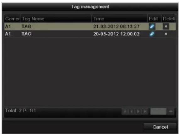
| Control Panel | Fades in/out the control field for playback control |
| Exit | Ends playback |
- In order to change the description of your marking, click on the process symbol. To remove, click on the delete symbol.
Right click when playback is running
Perform a right click on the playback image. The following options are available:
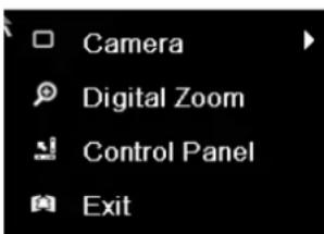
| Camera | Camera to be set |
| Digital Zoom | Enlarges the selected screen section digitally |
Main menu
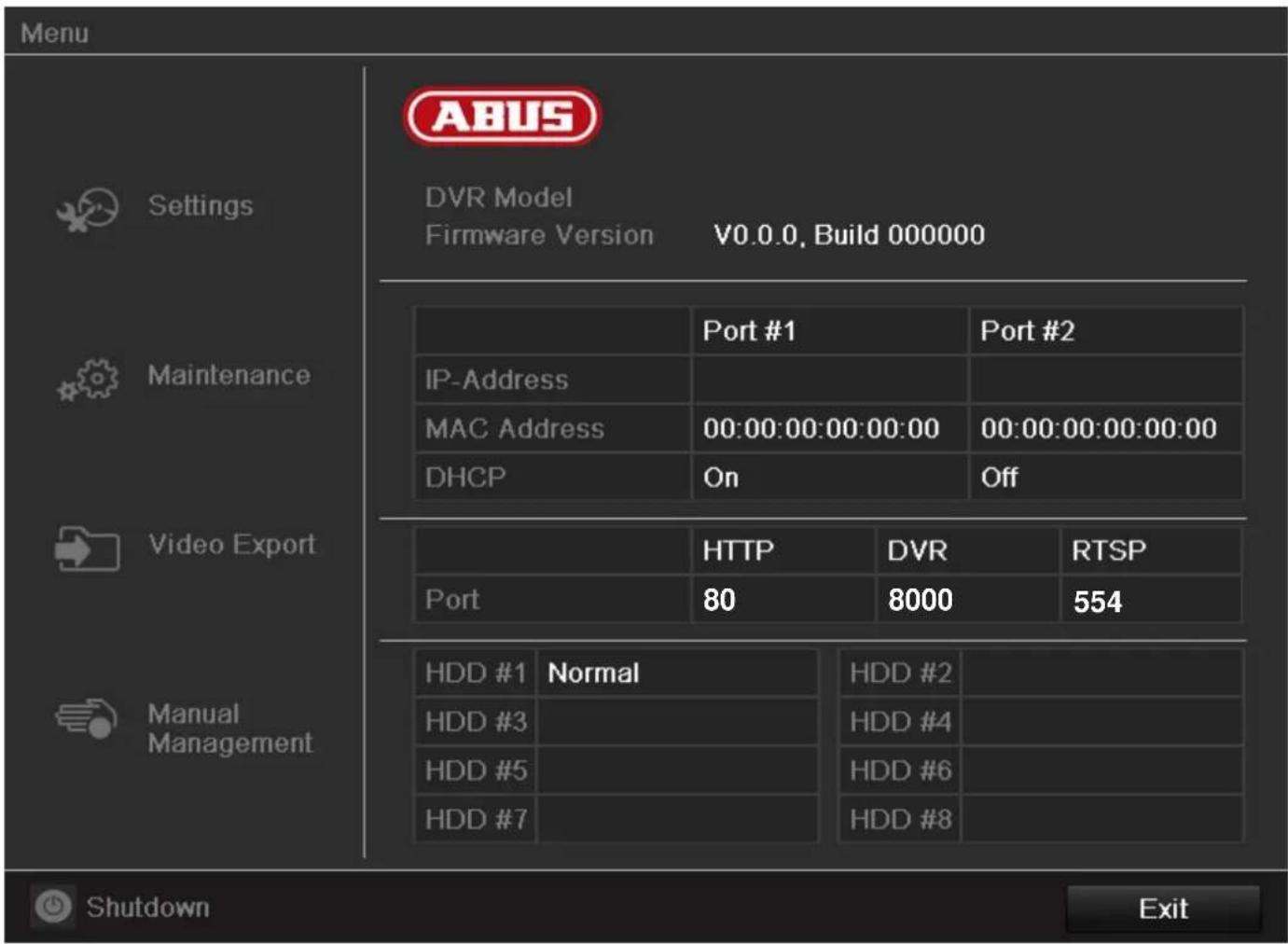
Menu overview
The following overview shows the main menus used to set and control the device.
Furthermore you can find important information regarding the devide on the right side of the menu.
- Click on the menu to open it.
- Click Exit to close the menu overview.
Menu description
| Menü | Beschreibung | siehe S. |
| Settings | Includes the menus Configuration, Camera, Record, HDD, Playback. | 122 |
| Maintenance | Device maintenance (new firmware update, log search, import/export configuration, reset to factory defaults etc Display network utilization. | 143 |
| Video Export | Feature for exporting saved recordings onto USB media. | 147 |
| Manual Management | Starts or ends the manual video and image recording of selected cameras, as well as the manual switching of alarm outputs. | 149 |
| Shutdown | Lock, shutdown or restart the device. | 149 |
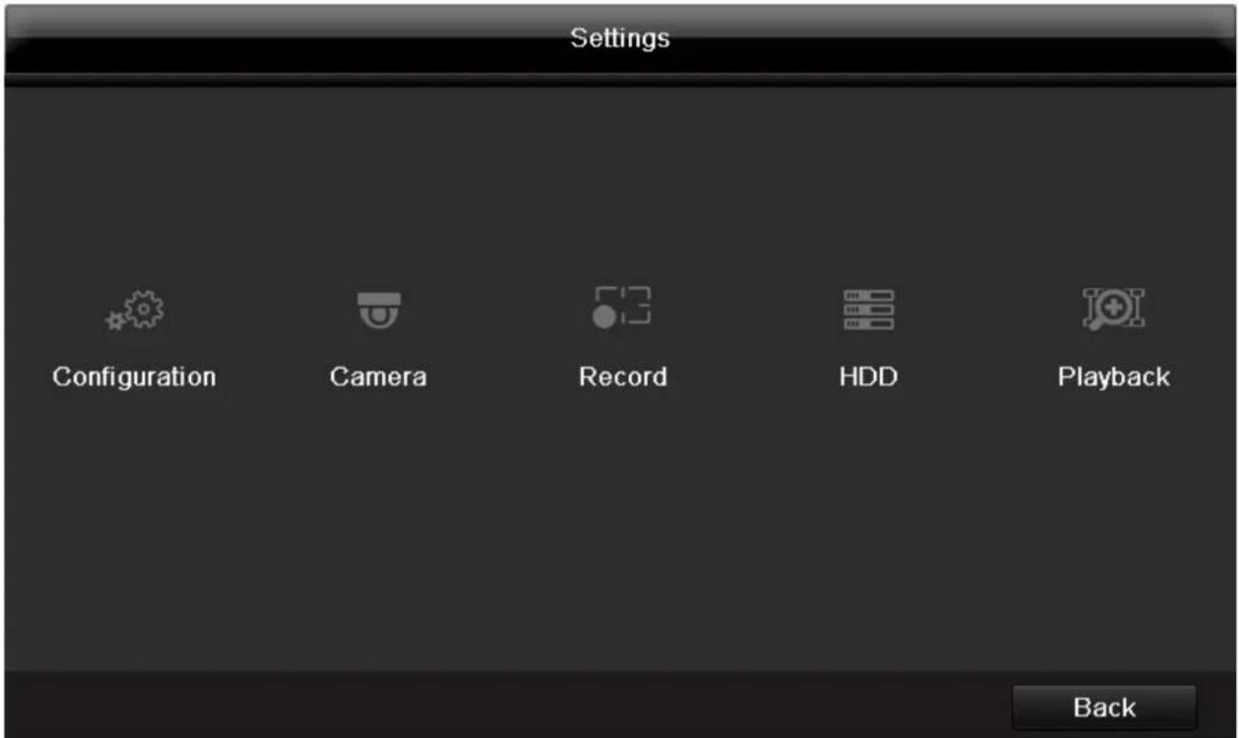
Menu description
| Menu | description | page |
| Configuration | Used for managing all device settings (General, Camera, Record, Network, Alarm, PTZ, RS232, Display, Exception, User). | 122 |
| Camera | Menu for setting camera parameters (OSD configuration, image mode, PTZ configuration, motion recognition etc.) | 129 |
| Record | Menu to set recording parameters (time plan, camera resolution, camera stream etc.). | 135 |
| HDD | Used for initialising or managing installed HDDs (assigning read/write functions, cameras, network HDD management etc.). | 138 |
| Playback | Parameter-controlled search for video or image recordings which were started by events like alarms or motion recognition, as well as alarm events and markings set in playback. | 141 |
Settings - Configuration

Note
The "Configuration" menu is used to manage all device settings.

Warning
Ensure that the date and time are set correctly.
IMPORTANT:
Subsequent changes to the settings can lead to data loss!
Ensure a data backup has been made in good time beforehand.
Overview
| Menu | Setting | Page |
| General | Language, video, time, date, mouse pointer, password, time zones and other settings | 122 |
| Network | Required network settings (manual IP, DHCP, PPPOE, DDNS etc.) | 124 |
| Alarm | Assignment and parameterisa-tion of detectors to alarm inputs and relay outputs | 125 |
| RS-232 | Parameters on the serial con-necton | 130 |
| Live View | Display settings and assign-ment of the event output | 130 |
| Warning | Behaviour of the device in ex-cepotional cases (HDD full, network discon-nected etc.) | 130 |
User
Adding and changing users, assigning authorisation rights
130

Note
Pay attention to the instructions in the corresponding sections.
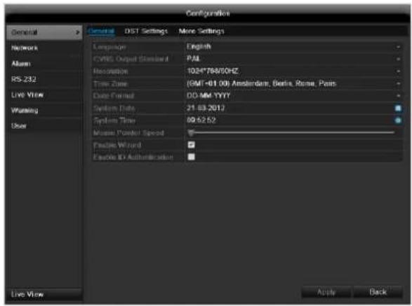
General
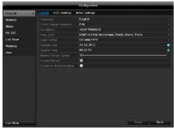
| “General” tab | Setting |
| Language | Language on the OSD |
| CVBS Output Standard | PAL / NTSC |
| Resolution | Resolution on the monitor |
| Time Zone | GMT (Greenwich Mean Time) |
| Date Format | MM-DD-YYYY, DD-MM-YYYY, YYYY-MM-DD |
| System Date/Time | Date and time |
| Mouse Pointer Speed | Set on the scroll bar (left = low speed; right = high speed) |
| Enable Wizard | Box not ticked: Wizard will not appear after restart of the device. Box ticked: Wizard will appear after restart of the device. |
| Enable ID Authentication | Box not ticked: In order to enter a menu no password has to be entered. At access by net- work the password has to be entered. Box ticked: Password must be entered in order to use the menu. |
| TAB “DST set-tings” | Setting |
| Auto DST Ad-justment | With an activated check box, the device converts automatically to summer time. |
| Enable DST | With an activated check box, an exact start / end date can be selected |
| From / To | Date of DST start / end |
| DST Bias | Daylight Saving Time Bias: Correc-tion of the DST to the reference time |
| TAB “More Settings” | Setting |
| Device Name | Unique specification of the device |
| Device Number | Used for unique identification when using remote control |
| Output Mode | Makes the image softer or sharper. |
| CVBS Output Brightness | Scroll bar (left = darker; right = brighter) |
| Operation Timeout | Never / 1 to 30 minutes – regulates how long the menu is shown |
Confirm the settings by clicking Apply and leave the menu with OK.
Network configuration
Correct network settings are essential in the following cases:
- When using remote control of the device and surveillance over your server

Note
Please read the following basic instructions before setting up the device.
A network is a connection of at least two network-capable devices.
Transmission types:
- Wired networks (e.g. CAT5 cable)
- Wireless networks (WLAN)
- Other transmission types (Powerline)
All systems have certain similarities, but can also differ in many ways.
Terms and definitions
An overview of relevant terms when using the device in a network can be found below.
| Parameter | Setting |
| IP address | An IP address is the unique address of a network device within a network. This address may only appear once within a network. Certain IP address ranges are reserved for public networks (e.g. the Internet). |
| Private address range | e.g. 10.0.0.0 - 10.255.255.255 Subnet mask: 255.0.0.0 172.16.0.0 - 172.31.255.255 Subnet mask: 255.255.0.0 192.168.0.0 - 192.168.255.255 Subnet mask: 255.255.255.0 |
| Subnet mask | A subnet mask is a bit mask used for making decisions and assignments during routing. 255.255.255.0 is the standard subnet mask in home networks. |
| Gateway | A gateway is a network device which allows all other network devices to access the Internet. This can be the computer connected to the DSL modem or – usually – the router or access point within the network. |
| Parameter | Setting |
| Name server | The name server is responsible for as-signing a unique IP address to a web address or URL (e.g. www.google.de). Also known as DNS (Domain Name Server).When a domain name is entered into a browser, the DNS searches for the corresponding IP address of the server and forwards the query on.The IP of the provider's DNS can be entered here. However, it is often sufficient to select the IP of the gateway. This then forwards the queries independently to the provider DNS. |
| DHCP | The DHCP server automatically assigns the IP address, subnet mask, gateway and name server to a network device.DHCPs are available in current routers.The DHCP service must be specially set and activated (see the corresponding manual for more information).Note:When using fixed IP addresses and a DHCP server, make sure that the fixed IP addresses are outside the address range assigned by DHCP. Otherwise, problems could occur. |
| Port | A port is an interface used for communication by different programs. Certain ports are fixed (23: Telnet, 21: FTP), whilst others can be freely selected. Ports are important for different applications (e.g. external access to the device over a browser). |
| MAC address | The MAC address (Media Access Control or Ethernet ID) is the specific hardware address of the network adapter. This is used for the unique identification of the device in a computer network. |
Network layout
The device must be physically connected to the network over a CAT5 cable (see the connections on page 84).
Note
Pay attention to the specific information and instructions on the network devices.
Several switches, routers and access points can be connected to each other. Firewalls and other security software can affect the network.

Warning
When using a router, the network clients (e.g. the recorder) can be connected to the Internet and vice versa.
Make sure to use protective measures to prevent unauthorised external access (e.g. firewall, changing passwords, changing ports)!
Network-configuration
| TAB | Settings |
| General | Settings for the local net and selecting the network mode. |
| PPPOE | PPPOE is used on ADSL connections and when using modems in Germany. Click on “Set” to enter the access data (ID and password) for your provider. |
| DDNS | Server for Dynamic Domain Name System management. Used for updating host names or DNS entries |
| NTP | Network Time Protocol Server for time synchronisation |
| Used to specify the e-mail settings which are sent as an e-mail to a specific address in the event of an alarm. | |
| FTP | Configure the address of an FTP server and the path for saving the files. |
| SNMP | Configure the parameters to receive information about the device status. |
| More Settings | Communication and HTTP port. |
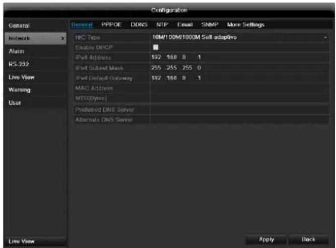
TAB General
| Parameter | Setting |
| Working Mode | See explanation, p. 123 |
| Select NIC | Select the connection for which to make the network settings. |
| NIC Typ | Set the transmission speed of the installed network card here. Tip: 10M/100/1000M self adaptive |
| Enable DHCP | Tick the box if the IP addresses are assigned dynamically via DHCP in the network. DHCP activated: Subsequent entry fields are inactive (parameters as-signed via DHCP). Note: If the IP addresses are assigned manually, ensure that DHCP is not active (box not ticked). |
| IPv4 Adress | Address of the network device in the network (manual assignment) |
| IPv4 Subnet Mask | Usually 255.255.255.0 |
| IPv4 Default Gateway | Address of the gateway for Internet access |
| IPv6 Adress 1 | Currently no functioning |
| IPv6 Adress 2 | Currently no functioning |
| IPv6 Standard Gateway | Currently no functioning |
| MAC Adress | Hardware address of the installed network card |
| MTU (Bytes) | Describes the max. size of the largest protocol data . |
| Preferred DNS Server | Address of the Domain Name Server (usually the IP address of the gateway) |
| Alternate DNS | IP address of the alternative DNS server |
| Default Route | LAN 1 or LAN 2 |

Note
In certain modes some of these settings cannot be selected.
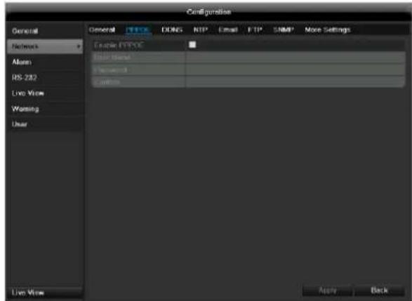
PPPOE
- Tick the PPPOE box, enter the user name (Internet access ID) and password, then confirm the password.
- Confirm the settings by pressing Apply.

Warning
Use PPPOE only if there is no router available.

DDNS
- To use the ABUS DDNS function, you must first set up an account under www.abus-server.com. Please note the FAQs on the website when doing this.
- Tick the "Enable DDNS" box, enter 'ABUS DDNS' as the "DDNS Type", then enter www.abus-server.com under "Server Address".
- Confirm the settings by pressing Apply. The IP address of your Internet connection is now updated on the server every minute.
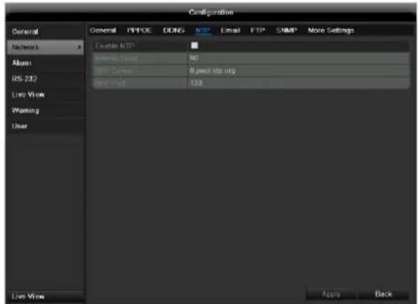
NTP

Note
The recorder can synchronise the time with an external server. Several server addresses are available on the Internet for this purpose.
-
Tick the "Enable NTP" box and then enter the interval at which the synchronisation should be made again. Enter the IP address of the NTP server and the NTP port.
-
Confirm the settings by pressing Apply.
In the event of an alarm, the device can send a message by e-mail. Enter the e-mail configuration here:
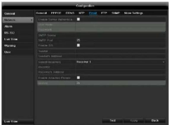
| Parameter | Setting |
| Enable ServerAuthentica... | Tick the box when authentication is made on the server of the Internet provider |
| User Name | E-mail account at the provider |
| Password | Password connected to the e-mail account |
| SMTP Server | SMTP server address of the provider |
| SMTP Port | Enter the SMTP port here (Default: 25) |
| Enable SSL | Tick the box to activate the e-mail encryption |
| Sender | Name of the sender |
| Sender's Adresse | Corresponding e-mail address for the e-mail account |
| Sender's Re- ceiver | Select three possible recipients for the e-mail |
| Receiver | Enter the name of the recipient here |
| Receiver's Adresse | Enter the e-mail address of the recipient here |
| Enable Attached Picture | Tick the box when camera images should also be sent with the e-mail as photo files |
| Interval | Select the interval between the individual recordings (2 to 5 seconds) |
- Enter the parameters of the e-mail notification.
- Click on Test to send a test e-mail.
- Please clarify if your settings are correct and you have received a confirmation mail. Then click on Apply.

Note
The device sends an e-mail to the specified recipients.
If the e-mail is not received, check the settings and correct them.
If necessary, check the spam filter of your e-mail client.

Note
Because of the cause of compatibility please do only use E-Mail clients where a dial-up via SMTP is possible.
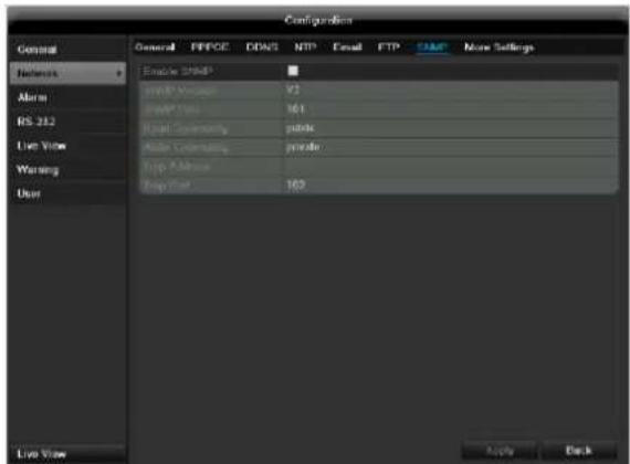
SNMP
| Parameter | Setting |
| Enable SNMP | Activate the checkbox to create a connection to SNMP software |
| SNMP Version | Version of the SNMP system |
| SNMP Port | Enter the SNMP port (Default: 161) |
| Read Community | Enter the “Key” according to the settings of your SNMP software. |
| Write Community | Enter the “Key” according to the set- tings of your SNMP software. |
| Trap Adresse | Enter the IP address of the SNMP manager |
| Trap Port | Enter the trap port (Default: 162) |

Note
SNMP is used for monitoring the device status. For this you need SNMP software not available from ABUS.
Confirm the settings by clicking Apply and leave the menu with Back.
More settings
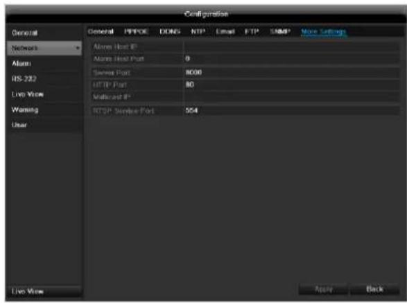
| Parameter | Setting |
| Alarm Host IP | Network address of the PC where the CMS is installed |
| Alarm Host Port | Port of your CMS Station |
| Server Port | Port for data communication (General: 8000) |
| HTTP Port | Port for web server (General: 80) |
| Multicast IP | In order to minimize traffic you can enter a Multicast IP. The IP address has to match the IP address of the PC running the CMS software. |
| RTSP Service Port | RTSP-port(Default: 554) |

Note
Server port 8000 and HTTP port 80 are the standard ports for remote clients and remote Internet browser access.

Note
With Alarm Host IP/Port you configure the address of your CMS software. The CMS software is notified when there is an alarm, and performs various reactions depending on the setting.
Alarm
Alarm status
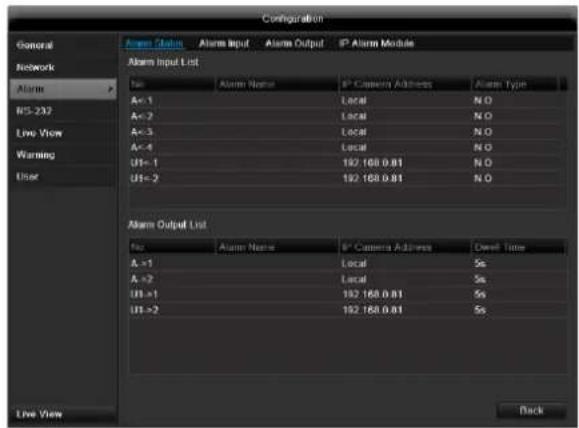
Here you see a list with all the alarm inputs and outputs and their current status.
Alarm input
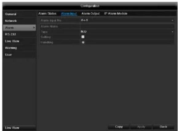
- Select a reaction in the case of an alarm by clicking the 'Setting' symbol for "Handling".
| Parameter | Setting |
| Alarm Input No. | Select the alarm input to make the settings |
| Alarm Name | Enter a clear description here (e.g. door contact on warehouse) |
| Type | N.O.: Normally open circuit N.C.: Normally closed circuit |
- Activate the alarm input by ticking the checkbox for "Setting".
- Define the response of the recorder when there is an alarm under "Handling".
- Click Copy to apply these settings for other cameras.
- Confirm the settings by clicking Apply and leave the menu with OK.
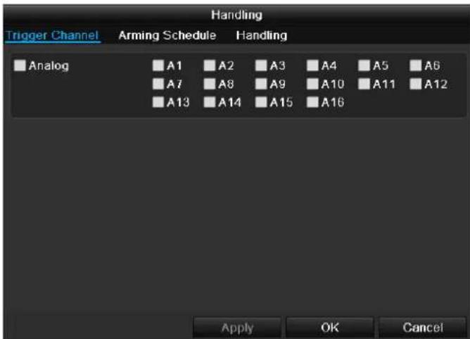
Handling
TAB Trigger channel
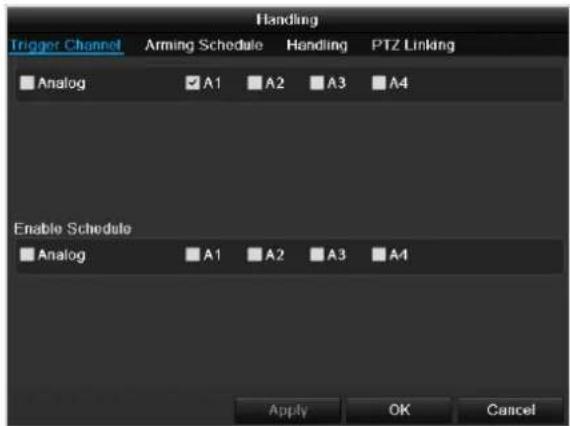
Tick a checkbox to select which camera channel is triggered in the case of an alarm.
TAB Arming schedule
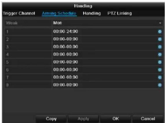
- Define the time at which the responses selected in the TAB "Handling" are activated when there is an alarm.
- Click Copy to apply these settings for other days of the week or the entire week.
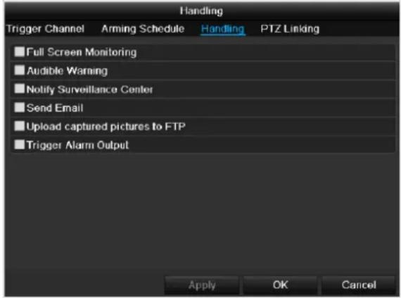
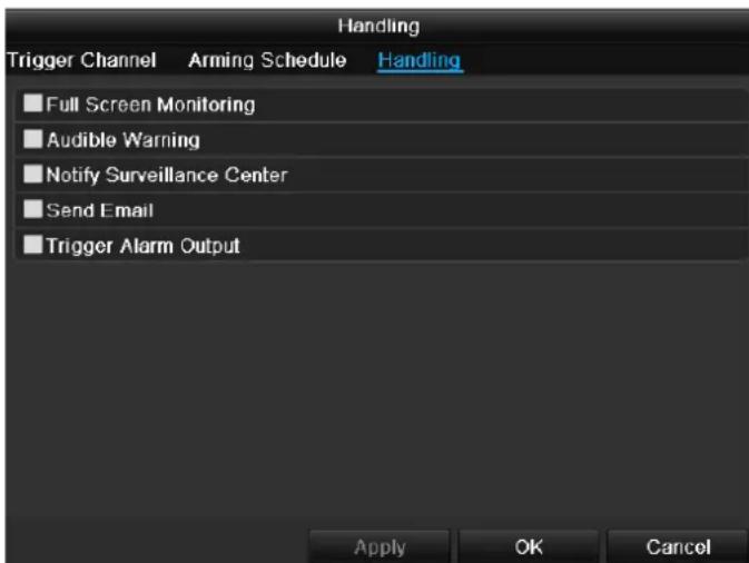
TAB Handling
Define the response in the case of an alarm:
| Parameter | Setting |
| Full Screen Monitoring | A message appears on the monitor. |
| Audible Warning | The device emits a repeating tone. |
| Notify Surveillance Center | Sends an alarm signal to a PC with ABUS CMS software. The software must be enabled and the recorder set to surveillance mode on the PC. |
| Send E-Mail | An e-mail is sent to a specific e-mail address (see page 124). |
| Trigger Alarm Output | see also page Fehler! Textmarke nicht definiert. |
Confirm the settings by clicking Apply and leave the menu with OK.

Note
To record with the aid of an alarm, you must set up the schedule under Recording (see p. 135).
TAB PTZ Linking
Currently no functioning.
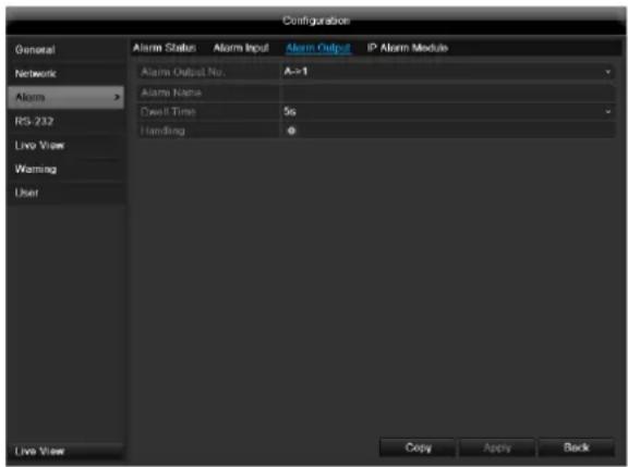
Alarm output
- Select an alarm output to be configured in the drop-down menu under "Alarm Output No."
- Assign any name to the alarm output in "Alarm Name".
- In "Dwell Time", select how long the alarm is triggered for.
- In "Handling", select the schedule for the alarm output.
- Click Copy to apply these settings for other alarm outputs.
- Confirm the settings by clicking Apply and leave the menu with OK.
RS-232
Currently no functioning.
Live view
See page 115.
Warning
i
Note
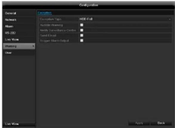
Enter the trigger under "Exception Type", for example:
HDD Full
- Disconnected
After doing this, specify the device behaviour.
Confirm the settings by clicking Apply and leave the menu with Back.
User

Warning
Note down the admin password. The following password is preset:
"12345"
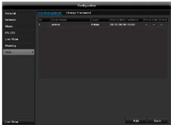
You can add new users, delete existing users and change the settings in the "User Management" menu.
- To add a new user, select Add.
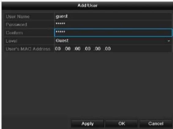
| Parameter | Setting |
| User Name | Unique identification |
| Password | Access code for the device (device management) Note: Change all passwords on a regu- lar basis, using a combination of letters and numbers. Note down all pass- words in a safe place. |
| Confirm | Enter the access code again here |
| Level | IMPORTANT: More access rights can be set on the Manager level than on the User level. |
| User's MAC Address | MAC address of the network adapter on the PC of the corresponding user Note: This limits access to the PC whose MAC address is entered here! |
- Enter the name and password and confirm the password in the field below.
- Select the level and enter the MAC address.
- Confirm the settings by clicking Apply.

Warning
Pay attention to the instructions below on assigning access rights.
Permission
Control the access rights of the user by clicking the "Permission" symbol. Only the access data of users added manually can be changed:
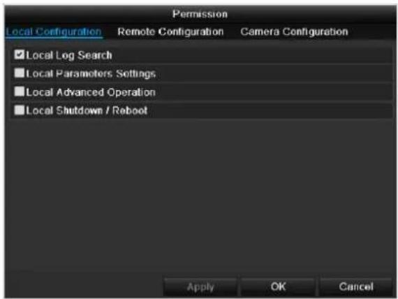

Note
The user can make the settings locally (i.e. on the device) or change the parameters.
The user can access the device via the network connection.
The "Camera Permission" tab is used to set access rights for individual cameras (network or local).
| Parameter | Setting |
| Local Configuration | Local Log Search Local Parameters Settings Local Advanced Operation Local Shutdown / Reboot |
| Remote Configuration | Remote Log Search Remote Parameters Settings Remote Serial Port Cnrol Remote Video Output Cnrol Two-way Audio Remote Alarm Control Remote Advanced Operation Remote Shutdown / Reboot |
| Camera Configuration | Camera Permission |

Warning
Change the general settings of the user (name, password, level, MAC address) by clicking the "Edit" symbol or in the TAB "Change password".
Camera
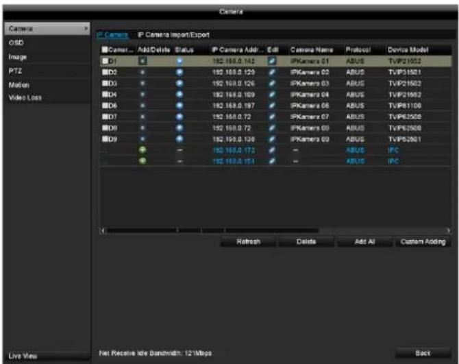
Camera
| Camera | Shows the camera number |
| Add | Adds a new network camera |
| Network camera address | Shows the set IP address of the camera |
| Edit | Edit the camera |
| Name | Shows the name of the network camera |
| Log | Displays the log |
| Device model | Shows the model |
| Refresh | Refreshes the list |
| Delete | Deletes a network camera |
| Add all | Add all existing network cameras |
| Custom | Settings for custom addition |
Click the + sign to add a camera to the system.
Click "Refresh" to search the network for ABUS network cameras.
Click "Add all" to add all existing network cameras.
Click "Custom" to add Onvif cameras..
i Note
In some cases, you need to enter the user names, password and http port by hand afterwards.
The available bandwidth shows you how much bandwidth is still available for setting up the network camera.
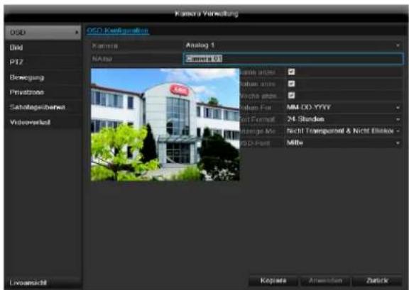
OSD
| Camera | Camera to be set |
| Camera Name | Allocation of camera name |
| Display Name | Activate / deactivate display of camera name in the live view |
| Display Date | Activate / deactivate display of date in the live view |
| Display Week | Activate / deactivate display of week in the live view |
| Date Format | Selection of date display type |
| Time Format | 12 hours / 24 hours |
| Display Mode | Settings relating to the presentation of camera name and date |
| OSD font | Changing the font size |
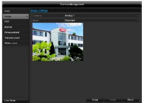
Image
Select the camera channel to be processed at "Camera". Adapt the camera image to light conditions at "Mode" by means of specified settings or with user-defined settings.
PTZ

Note
Here you can set up presets and patrols for the
TVIP2xxxx network cameras.

Saving and retrieving presets
- Use the arrow buttons to move the network camera to the required image section and save the position, for example as Preset 1
- Click on Call up to move to Preset 1.
Setting up and calling up patrols
- Create several presets to use for the patrol
- Click on + to select a preset
- Add more presets to set up the required patrol.
- Then click on the play symbol to start the patrol.

Note
You can also start the patrol directly in the live image of the respective network camera.
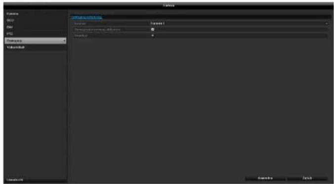
Select the checkbox for motion detection.
The motion detection in the network camera must also be activated. For further details, refer to the network camera manual.

Note
In order to record using the motion recognition, you must set the time plan at recording (see p. 135).
Handling
Trigger Channel
When "Reaction" is clicked, the TAB Trigger channel appears (only with motion recognition):
Select one or more camera channels that should carry out a reaction in the event of an alarm.
Confirm the settings by clicking Apply and leave the menu with OK.
Motion
Select the camera channel under "Camera".
Armin Schedule
Select the TAB Arming Schedule.
Here you set the times when the reactions in the TAB Reaction are triggered.
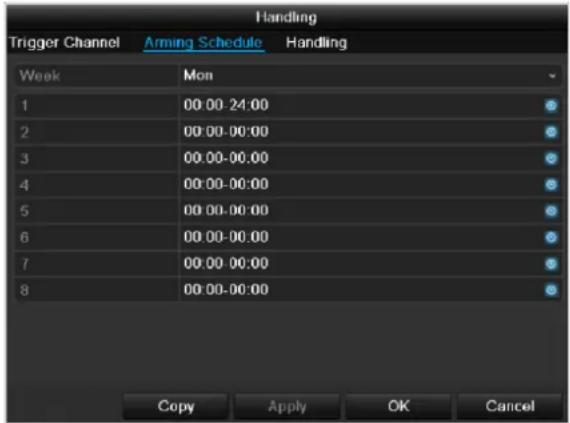
- Select the day and enter the schedule.

Note
You can define up to 8 time periods (each from 00:00 to 00:00). The times in the individual periods must not overlap.
- Select whether the settings should be applied to all days of the week with using Copy.
- Confirm the settings by clicking Apply and leave the menu with OK.
Handling
Click on the TAB Handling.
Here you can configure the behavior of the recorder during a detected event (for example: motion got detected) by clicking the respective check box.
| Parameter | Notification |
| Full Screen Monitoring | The camera is displayed as a full-screen picture in live cast |
| Audible Warning | The device emits a repeating tone |
| Notify Surveillance Center | Sends an alarm signal to a PC with the ABUS CMS software. For this, the software must be running and the recorder must be in surveillance mode. |
| Send E-Mail | An e-mail is sent to a specific e-mail address (see page 124) |
| Trigger Alarm Output | see page 124 |
- Confirm the settings by clicking Apply and leave the menu with OK
Record
Setting up
Open the main menu and click on record:
Schedule
The schedule is used to specify the recording times and triggers (recording type) for the cameras. Click on the "Schedule" tab:

Note
Because there is no difference between the settings for the TABs record and instant image, these are only listed once.
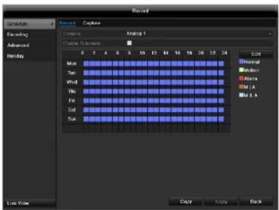
In the OSD, the hours of the respective days are listed from left to right (the days are listed from top to bottom). A colour key is shown underneath the days (i.e. the recording periods in the schedule are shown in colour according to the trigger (recording types)).
| Colour symbol | Key |
| Blue | Normal recording: Period in hours |
| Yellow | Motion detection |
| Light blue | Motion detection and alarm |
| Red | Alarm |
| Grey | No selection |
| Brown | Motion or alarm |
- Select the camera and click on the check box Enable Schedule.
- Click on Edit to specify the type and duration of the time plan
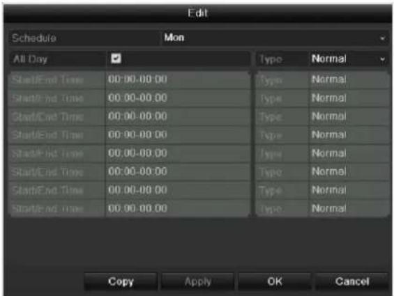
- Define the day to be set in the pull-down menu at 'Schedule'.
- Activate/deactivate 'All day'. If the full day is active, no definite times can be entered as the setting is now valid for the whole day.
- To make specific time settings, deactivate the "All Day" box.

Application example
Recording should run from 11:00 to 07:00. 2 time zones must be set up for this:
-
11:00 AM - 24:00PM
2.00:00AM-7:00AM -
Specify the recording type in the drop-down menu:
Time
Motion detection
Alarm
Motion detection or alarm
Motion detection and alarm

Note
To record using motion detection or the alarm, you must first set this up in the Camera menu (see p. Fehler! Textmarke nicht definiert. "Setting up of zones") or Configuration (see p. Fehler! Textmarke nicht definiert. "Alarm").
- When making a specific time setting, you can define up to 8 time periods (each from 00:00 to 24:00). The times in the individual periods must not overlap.

Note
The "Time" recording type defines the time window where a recording is made.
The other events (e.g. motion detection and/or alarm) only trigger the recording after the specific event has occurred.
-
At Copy you can take on this setting for other days on the whole week.
-
Finalize your settings in the record screen with Apply and then OK.
Encoding
TAB Record
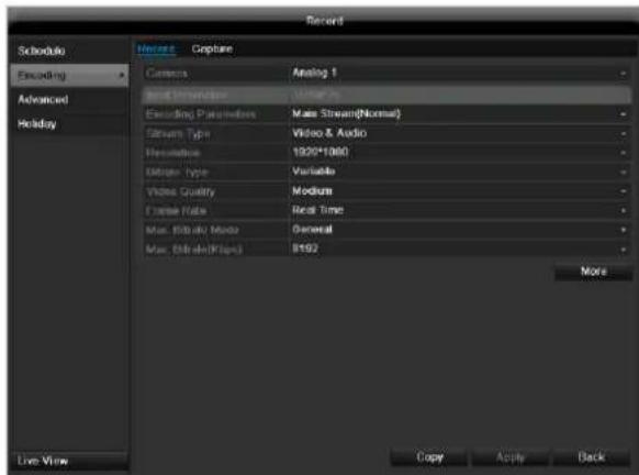
The following setting options are available in this submenu:
Confirm the settings by clicking on Apply and exit the menu with OK.
| Pre-record | Recording period before an alarm (in seconds) |
| Post-record | Recording period after an alarm (in seconds) |
| Record Audio | Audio record yes/no |
Confirm the settings by clicking on Apply and leave the menu with OK.

TAB Captured
The following parameters are adjustable:
| Camera | Camera to be set |
| Parameter Type | Schedule or event |
| Resolution | Auto, 4CIF(704x576), CIF(352x288), QCIF(176x144) |
| Picture Quality | different qualities +++: middle quality +++++: high quality |
| Interval | Single images are saved every 1-5 seconds according to event or time plan |
Confirm the settings by clicking Apply and leave the menu with Back.
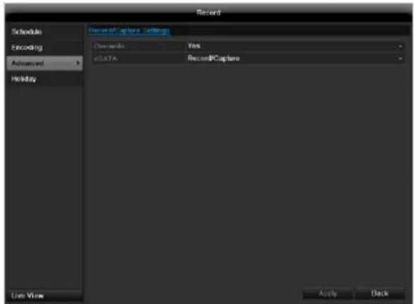
Advanced settings (TVVR45030)
| Overwrite | You can specify whether older re-cordings are deleted when the HDD memory is full |
| eSATA | Specify if an eSATA hard disc connected by USB should be used for exporting, or for additional re-cording/image storing. |
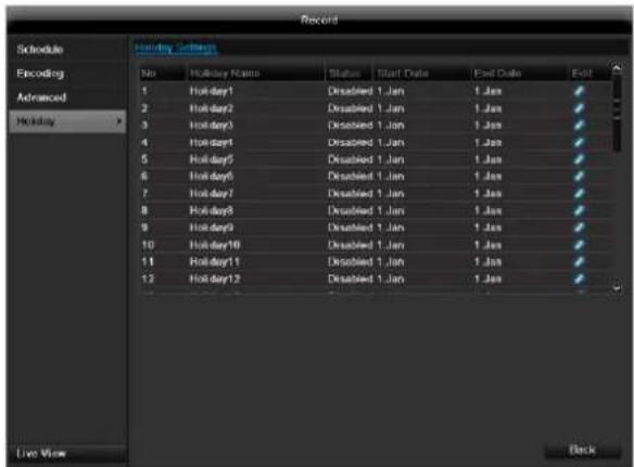
Holidays
In this sub-menu, 32 different recording settings for vacations or public holidays can be applied.
To apply these settings click on the "Edit" symbol:
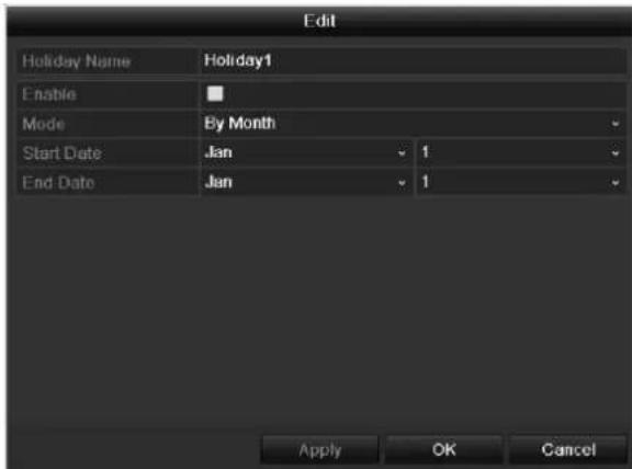
| Holiday Name | Manual name entry of the vaca- tion or holiday |
| Enable | Activate or deactivate the set va- cation |
| Mode | According to date / week / month |
| Start Date | Selection of start date / start time |
| End Date | Selection of end date / end time |
Confirm your settings with Apply and OK.
HDD
HDDs

Note
The device manages up to eight 3.5" SATA hard disk drives (only TVVR45030).
For additional data security, an e-SATA hard disc can be optionally connected.
Each of the installed HDDs must be initialised before the device can be used for recording. The device only detects the HDD and its assignment after initialisation has been made.

Warning
All data is deleted from the HDD during initialisation.
Ensure a data backup has been made in good time beforehand.
Installing the HDD
- Disconnect the device from the mains power and open the cover.
- Observe the applicable ESD guidelines when handling electronic devices and ensure they are earthed.
- Do not open the device in rooms with carpets or other surfaces that can become electro statically charged.
- Avoid bodily contact with all components on the PCB.

Warning
If you have questions regarding the information or cannot find the information you need, please contact your maintenance specialist.
- Install the HDD and then connect it.
- Reattach the cover and connect the device to the mains power supply.
- Switch on the device and start the HDD menu.

Note
If the initialised HDD is not displayed, check the connections
Click on "HDD" in the menu to define settings relating to hard disc administration
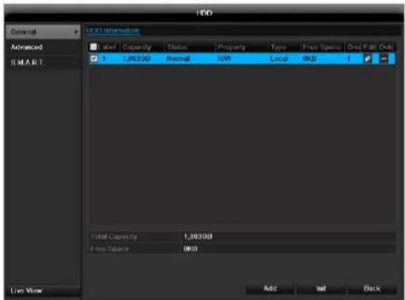
HDD Management parameters
| HDD information | |
| Label | Shows the internal connection number |
| Capacity | HDD capacity (in GB) |
| Status | Shows the current status of the HDD: Not initialised Normal Error |
| Property | ·Redundancy: Works redundantly for data security ·Read-only: Read-only protection ·R/W: Read and write |
| Type | Local: Device HDD NFS: Network HDD If possible, avoid using NFS storage due to compatibility problems that may occur. |
| Free Space | Shows the approximate free memory for recordings |
| Group | HDD group (1 is preset) Recordings can be assigned to groups |
| Edit | Define hard disc settings (First adjust the camera groups; see also p.32) |
| Delete | Removal of the hard disc |
- Select the HDD by ticking the corresponding box.
- Start the process by clicking on Init.
- Confirm the prompt by pressing OK.
- The status bar shows the progress of the initialisation.
HDD settings of the cameras
Click on the sub-menu "Advanced".
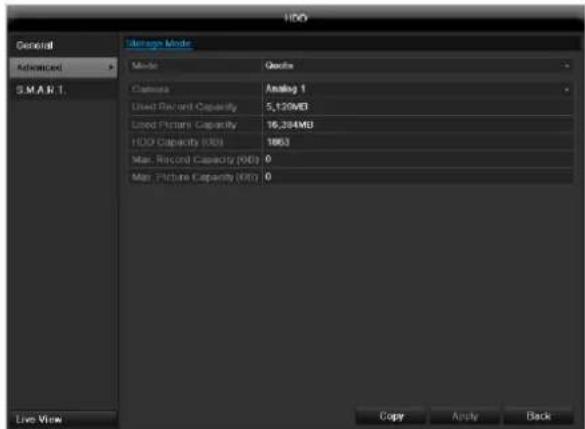
Mode:Quote
Specify the maximum recording size per camera on the hard disc.
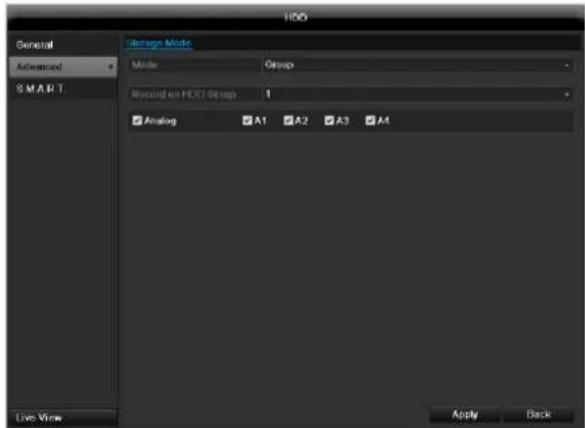
Mode:Group
- Select a hard disc group in the drop-down menu.
- By activating the check box, specify which cameras should be saved on the hard disc group.
- Click on Apply and confirm the restart in the next window with OK.
Hard disc setting

Note
To be able to define these settings, you must have allocated cameras to a hard disc group (see HDD settings of cameras).

Click on the "Edit" symbol. A pop-up window appears:
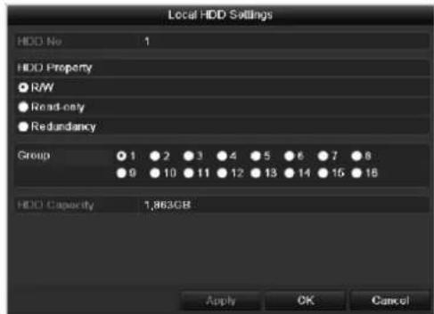
| HDD No. | Selecting hard disc by means of in-ternal connection number |
| HDD Property | • R/W: Readable and writeable • Read-only: Write protection • Redundant: operating redund-antly for data security. |
| Group | Selection of hard disc group |
| HDD Capacity | Hard disc memory |
Confirm the settings by clicking Apply and leave the menu with OK.

Warning:
If only one HDD is installed and this is set to "Read-only", then the device cannot make recordings.

Redundancy:
At least two HDDs are installed.
The redundant HDD makes an extra copy of the recordings. This is used as a data backup.

Warning:
If you want to use redundancy you have to activate the redundant storage in the recording menu (see also p. 136)

R/W
At least one HDD must have the R/W status (Read/Write). Otherwise, no recordings are possible.
Checking the HDD status
The status of each HDD can be checked in the "Maintenance" menu. S.M.A.R.T. information (Self-Monitoring, Analysis and Reporting Technology) is stored in the log data.
- Call up the log file and search according to the information/S.M.A.R.T. HDD (see page 140).
Setting up the HDD alarm
You can specify alarms to inform you of HDD errors.
To do this, call up Warning in the "System Settings" menu (see page 130).
S.M.A.R.T.
S.M.A.R.T. means Self-Monitoring Analysis and Reporting Technology.
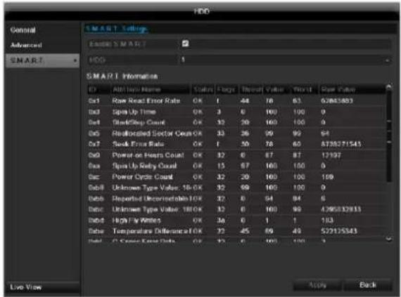
Information on the hard disc status is displayed in this sub-menu.
This information helps to recognize hard disc errors. For this reason, do not deactivate this feature if possible.
Note
The log files saved for S.M.A.R.T. can be found in the menu Maintenance at "Log search" (see page 143).
Playback
Press Configuration in the main menu and then Playback to search for video recordings after an event or a marking, or to view your saved images.
Continuous Recording
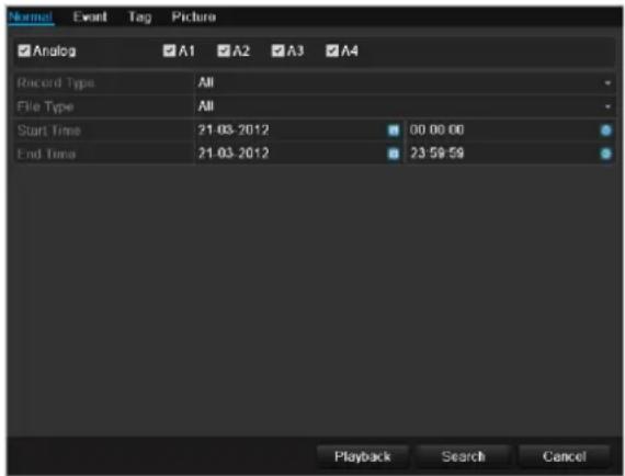
The following settings are available:
| A1 - A4 | Camera to be set |
| Record Type | Schedule, motion detection, alarm or motion detection and/or alarm, manual recording, all |
| File Type | Locked, unlocked, all |
| Start Time End Time | Enter the date and time |
- Click on Search to search for recordings with the corresponding settings. The results are then shown:
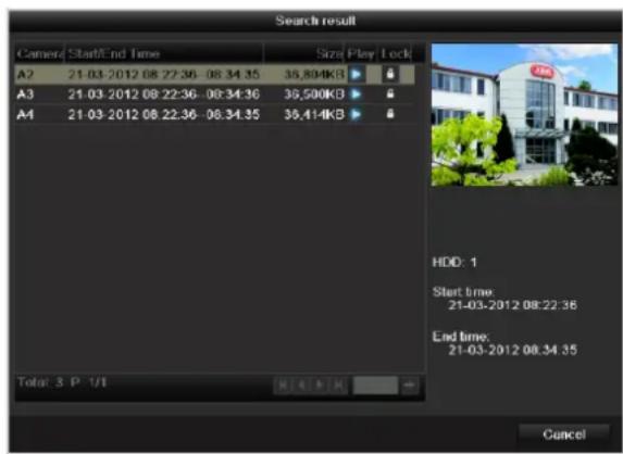
- Select the recording by clicking on the line and then on "Play"-symbol.
Note
You can return to events search at any time in the playback mode by performing a right click and selecting 'Video Search'.
i Note Theo
The sub-menus 'Tag' and Picture are almost identical with the menu described above and are therefore not listed separately. In the sub-menus Tag, searching does not take
place according to recording type, rather according to identification or a keyword of the markings' name
Event
Please klick on the TAB ,Event".
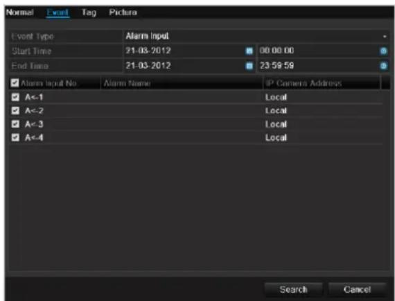
A list with all alarm inputs is displayed.
Select at 'Event type' whether the search should take place at alarm 'Alarm input' or motion 'Motion recognition' after recording.
Select one or more alarm inputs by activating the check box.
Klick on Search.
Select one of more alarm recordings on the list that appears. Click on Details to receive more exact information on the recordings.
Marking
Click on the "Marking" tab.
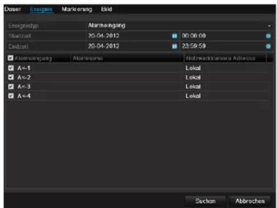
Select one or more network cameras by activating the checkbox.
Click on Search.
Select one or more markings from the list which appears. Click on Details to obtain more information about the markings.
Image
Click on the "Image" tab.
Select one or more network cameras by activating the checkbox.
Click on Search.
Select one or more images from the list which appears.
Click on Details to obtain more information about the images.
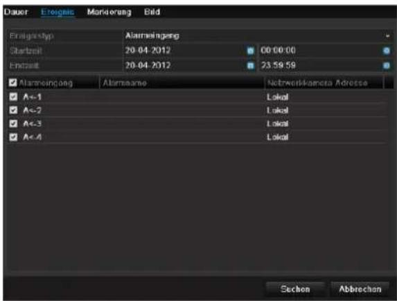
Maintenance

Note
This menu is used for device maintenance, and should only be operated by experienced users.
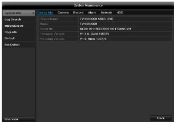
| Menu | Setting | P. |
| System Info | Device information (serial number, firmware status etc.) | 143 |
| Log Search | A search of recordings or information (S.M.A.R.T. HDD status) can be made in the log file according to certain criteria (alarms, exceptions, operation or information). | 143 |
| Import/Export | Used to export or import the settings | 144 |
| Upgrade | Carries out a firmware upgrade | 144 |
| Default | System reset | 145 |
| Network | Displays the transmission and reception rate of the recorder | 145 |
System Info
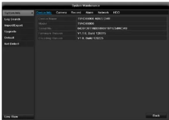

Note
The information menu shows the technical data for the device and information on the various settings of the cameras, recording etc.
This can be useful for support queries, for example.
Log Search
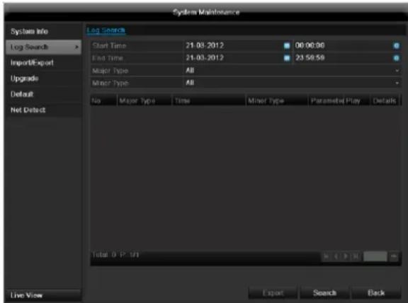

Note
An event search can be made according to the following main types, events and parameters:
All
Alarm
- Exception
Operation
Information
| Filter1 | Filter2 |
| All | - |
| Alarm | · All · Alarm Input / Output · Start / Stop Motion Detec-tion · Start / Stop Tamper-proof |
| Exception | · All · Video Loss Signal · Video Signal Exception · Illegal Login · HDD Full · HDD Error · IP Conflicted · Network Disconnected · Record / Capture Exception · Input / recording resolution mismatch |
| Operation | · All |
| • Power On • Abnormal Shutdown • Start / Stop Audio • Local Operation, e.g.: Shutdown / Reboot / Login /Logout / Configure Parameters / Upgrade / Start Recording • Remote Operation, e.g.: Export Record File / Alarm Arming / ... | |
| Information | • All • Local HDD Information • HDD S.M.A.R.T. • Start / Stop Recording • Start / Stop Capture • Delete Expired Record • NetHDD Information |
- Select the event you wish to search for in the log, then select the sub-parameter.
- Enter the date and time under "Start Time" and "End Time", then click on Search.
- The results are then displayed:
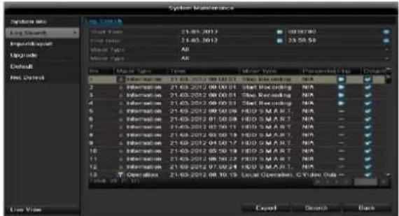
- The pages are changed using the navigation bar:

(1) (2)
(3) (4)
(5)
(6)
Note
To scroll forwards or backwards press (3) or (2).
To jump to the first or last page press (4) or (1).
To go to a specific page number enter it in (5) and confirm by clicking (6).
- Click on Details to see more detailed information.
- Click on Play to start the recording for the event, when necessary.
- Click on Export to back up the log file on a USB medium.
Import/Export
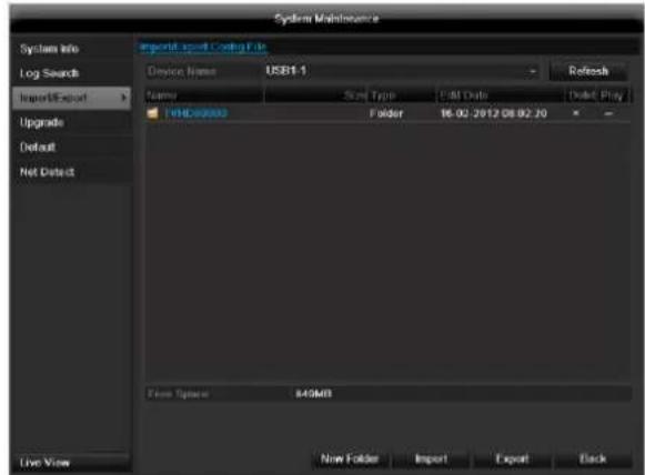
i
Note
The configuration data contains all settings made on the device since the start of operation. This data can be saved on a USB medium. You can then configure another device identically, for example.
Upgrade
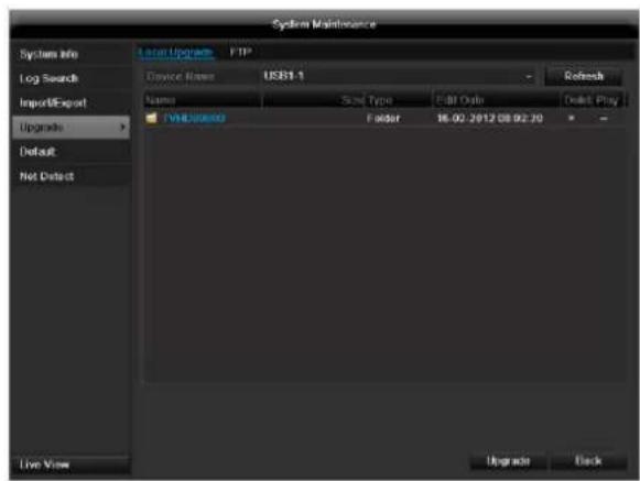
i
Note
A device upgrade can be made from a USB device or over the network via FTP.
- Copy the upgrade file to the main directory of a USB stick.
-
Connect the USB stick to a USB port on the device.
-
Select the USB port (click on Refresh, if necessary).
- Select the upgrade file and click on Upgrade.
- Wait until the device reboots.
- Check the firmware status in the "Maintenance" menu under "System Info".
Default
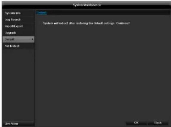

Note
In this process, the device is reset to the factory default settings.

Warning
All settings made since the start of operation are deleted (cameras, recording settings, PTZ, alarms etc.)!
Avoid data loss by backing up the settings in advance. These can be imported again following the system reset.
Network
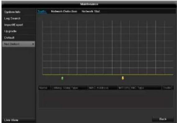

Note
Information regarding the network traffic and network interfaces are shown here.
TAB network load
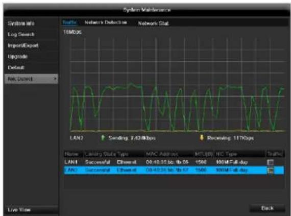
The amount of received and sent data is displayed graphically.
Depending on the network settings, the status and information for one or two network connections is shown in the field underneath the graph.
TAB Network Detection
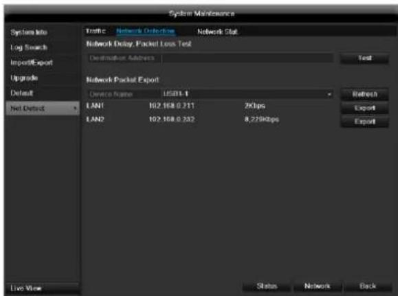
In "Destination Address", you can check the connection to another device, such as a computer ('pinging'). Enter the network address of the device to be checked (e.g. 192.168.0.25) and press Test.

Information on two parameters appears:
| Parameter | Setting |
| Average delay | The time the pinged device needs to reply. |
| Packet loss Rate: | Displays the percentage of packets that were not transmitted |
i
Note
If the packet loss rate is high, we recommend that the "Network Test" is repeated.
i
Note
If the packet loss rate is still high, you should check that the cables are correct and not damaged.
The higher the packet loss rate, the poorer the connection between the pinged device and recorder.
For "Network Packet Export", you can export the settings of the individual connections or - depending on the setting - the connection.
- For "Device Name", select a storage medium to save the settings to.
- Click Export.

After the progress display finishes and initialization is successful, an information window appears. Close it with OK.
-
Click Status to display the status of the LAN connections (connected/not connected).
-
Click Network to change your network settings (see p. 124).
TAB Network Stat.
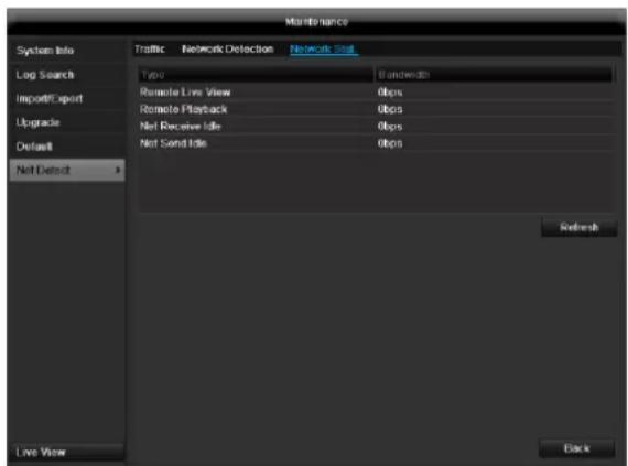
Displays all used in- and outcoming bandwidth.
Video Export
Duration
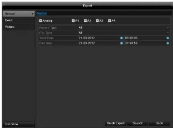
i Note
The export function is used to store important recordings on connected external media, such as:
USB media
USB HDD
DVD writer
-
When "Quick export" is selected, all recordings of the selected time span are exported. Please note that not more than 24 hours can be exported.
-
Enter the parameters.
- Click on "Details" to limit the search
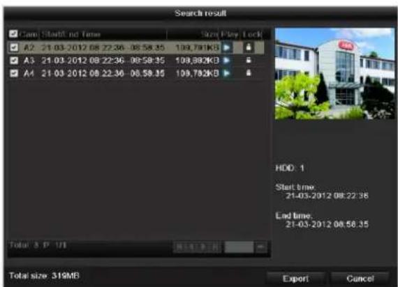
- The file size of the individual recording and the total size of all found recordings are displayed.
- By clicking the "Playback" symbol you can view the respective recording.
- To block or unblock a file click on the "Lock" symbol.
- Click on Export to access the export screen.
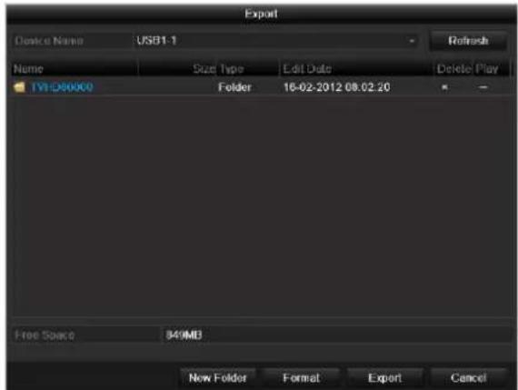
- Select the connected medium used for data storage from the drop-down menu.
- If the medium is not displayed, click on Refresh.
- If the medium is still not displayed, disconnect it from the device and reconnect the medium again. See also the manufacturer's specifications.
- Click on Export to start the export process. The progress of the export process is then displayed.


Note
After the storage process is completed, the data on the medium can be selected and played on the player (which was also backed up). In this way, you can check whether the export has been made successfully.
Event (event type 'Alarm input')
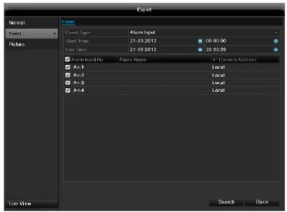
Define the time span of the recording being searched for by means of the selection fields at "Start time" and "End time". Select the alarm input by activating or deactivating the check box and click Search.
Event (event type 'Motion')
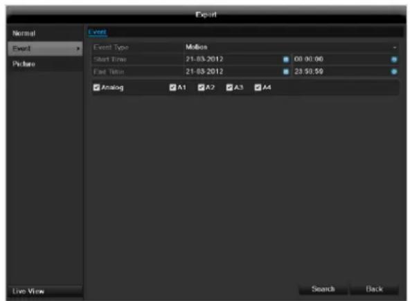
Define the time span of the recording being searched for by means of the selection fields at "Start time" and "End time". Select the camera by activating or deactivating the check box and click Search.
For both types of event, the following window appears after activating the Search button:
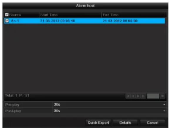
Select the files to be exported by activating or deactivating the check box. You can set the pre-alarm and post-alarm time at "Pre-play" or "Post-play". In this way you can define the length of your export video.
Click on Details to view the selected video. For more exact information on the Details window, see DURATION (p. 147).

Note
The "Pre-play" recordings can only be viewed when recording has been carried out before the alarm.

Note
The sub-menus "Normal" and "Picture" are similar and are therefore not listed separately.
Manual Management
Press the REC button or go to panic recording in the main menu in order to start a manual image / video recording or to switch to an alarm output.
Record
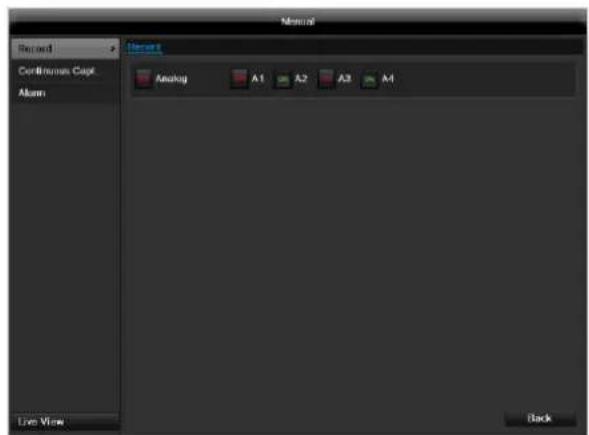
Select the camera to start manual recording by clicking the corresponding button.

Note
Click "Analog" to record all connected cameras.
Continuous Capture
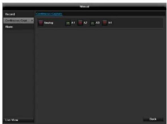
Select the camera to manually record continuous instant images. You can set the time interval in which these are recorded in the recording menu (see p. 135). Click the control button for this.
Alarm
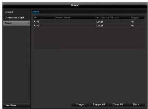
In order to switch on one of the alarm outputs, select the alarm output with a left click and click on Trigger for one, or Trigger All, to switch on all outputs. To reset the output(s) again, click on Clear or Clear all.
Shutdown
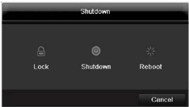

Note
- Select "Lock" to lock the operating menu.
- Select "Shutdown" to switch off the device.
- Select "Reboot" to reboot the system (switch off and back on).
Troubleshooting
Before calling the Service department, read the following information to determine the possible cause of a malfunction.
| Malfunction | Cause | Solution |
| No power | Mains cable not connected | Connect the mains cable securely to the socket |
| Power switch set to OFF | Turn the power switch to ON | |
| No current in the power socket | Use another device on the socket, where necessary | |
| No image | Screen not set for reception | Set the correct video input mode until an image from the recorder appears |
| Video cable not connected properly | Connect the video cable securely | |
| Connected modem is switched off | Switch on the monitor | |
| No sound | Audio cables not connected properly | Connect the audio cables securely |
| Devices connected over the audio cables are not switched on | Switch on the devices connected over the audio cables | |
| Audio connection cable is damaged | Replace the cable | |
| HDD is not working | Connection cables not connected properly | Connect the cables securely |
| HDD defective or not system-compatible | Replace with a recommended HDD | |
| USB port not working | Device not supported | Connect a compatible USB medium (USB 2.0) |
| USB hub is in use | Connect the USB medium directly | |
| Network access not possible | Network cable connections are loose | Connect the network cable |
| Network settings are incorrect (DHCP, IP address etc.) | Check the network configuration and correct it, ifnecessary (see page 124). | |
| Remote control is not working | Batteries inserted with the wrong polarity or are empty | Replace the batteries. To control the device with the remote control, point it at the remote control sensor on the device |
| Remote control too far away from the recorder | Use the remote controller within 7 metres from the device | |
| Signal blocked by obstruction between the remote control and recorder | Remove the obstruction | |
| Lighting too bright or fluorescent tubes in use? | Switch off strong fluorescent lighting in the immediate vicinity | |
| Recording not possible | No HDD or HDD is not initialised | Install and initialise the HDD |
| Sudden deactivation of the device | Temperature inside the device is too high | Clean the device and remove any obstructions from the ventilation area |
Device cleaning and care
Note
- Your device requires no maintenance.
- Protect the device from dust, dirt and moisture.
Technical data
Subject is to alterations and errors. The dimensions are approximate values.
| ABUS digital recorder | TVVR45030 |
| Video compression | H.264, MPEG-4 |
| Hybrid-compatible | - |
| Camera inputs | 32 |
| Camera outputs | none |
| Monitor outputs | Monitor: 1 x BNC (1.0 V p-p, 75 Ω), 1 x VGA, 1 x HDMI |
| Operating mode | Triplex |
| Resolution (live view) | HDMI: 1920*1080/60Hz(1080P),1600x1200/60Hz, 1280*1024/60Hz, 1280*720/60Hz, 1024*768/60Hz VGA: 1920*1080/60Hz,1600x1200/60Hz, 1280*1024/60Hz, 1280*720/60Hz, 1024*768/60Hz BNC Output: PAL: 704x576, NTSC: 704x480 |
| Resolution @ frame rate per camera (recording) | Max. 1920 x 1080p @ 25fps |
| Total frame rate | 800 fps |
| Compression levels | Depends on used network camera |
| Pre-alarm/post-alarm memory | 0-30 sec. / 5-900 sec. |
| Storage medium | 8x SATA HDD |
| Data backup | 3 x USB 2.0 |
| Views | 1 / 4 / 6 / 8 / 9 / 16 |
| Recording modes | Manual, schedule, motion detection, alarm, motion detection and alarm, motion detection or alarm |
| Search modes | By event, date and time |
| Alarm inputs (NO/NC) | 16 |
| Alarm outputs | 4 (Loading capacity: 12V DC/1 A) |
| User levels | 2 (max. 31 users) |
| Network connection | 2 x RJ45 10/100/1000 Mbps |
| Parallel network access | 128 camera connections |
| Network functions | Live view, playback, data export, settings |
| DDNS | √ |
| NTP | √ |
| PTZ control | RS-485 |
| PTZ protocols | PELCO-D, PELCO-P, Samsung, LG-MULTIX |
| Alarms | Acoustic warning, OSD signal, e-mail,CMS |
| Audio | Line In: 1 x Cinch (2.0 V p-p, 1000 Ω) - only for network transmission Audio Out: 2 x Cinch (600 Ω) |
| Control | USB Mouse, remote control |
| Software | ABUS CMS software |
| OSD languages | German, English, French, Dutch, Danish, Italian, Polish, Czech, Spanish, Swedish |
| Power supply | 100~240VAC |
| Power consumption | <55W (without HDD) |
| Operating temperature | -10 °C+55 °C |
| Dimensions (WxHxD) | 470 x 90 x 445 mm |
| Weight | ≤ 8 kg (without HDD) |
| Certification | CE |
HDD storage capacity
In addition to the actual storage capacity of the installed HDD, the required storage space for recording and surveillance depends on the set resolution and frame rate of the recording.
On the included CD you can find a program in order to calculate the required amount of memory. In addition you find this software for download on our homepage together with the ABUS CMS software.
Overview monitor output combination
| HDMI + VGA | HDMI + CVBS | VGA + CVBS | HDMI only | VGA only | CVBS only |
| ✓ | ✓ | ✓ | ✓ | ✓ | ✓ |
Disposal
Information on the EU directive on waste electrical and electronic equipment
To protect the environment, do not dispose of the device with domestic waste at the end of its service life. It can be disposed of at one of the appropriate collection points in your country. Please obey your local regulations when disposing of material.

Dispose of the device in accordance with EU directive 2002/96/EC - WEEE (Waste Electrical and Electronic Equipment). If you have any questions, please contact the department of your local authority which is responsible for waste disposal. Used equipment can be disposed of, for example, by your local or municipal authority, the local waste disposal company or your dealer.
Information on handling batteries
- Always insert batteries with the correct polarity. Never attempt to recharge the batteries supplied and do not throw them into naked flames under any circumstances. Do not use different batteries at the same time (old and new, alkaline and zinc-carbon etc.). Remove the batteries if the device is not used for a long period of time. If used improperly, there is a risk of explosion and leaking batteries!
- Take environmental protection into account - used batteries should not be disposed of in domestic waste! They must be taken to a collection point for used batteries.
- Make sure that batteries are kept away from small children. Children may put batteries in their mouths and swallow them. This can cause serious harm to their health. If this happens, consult a doctor immediately.
-
Do not charge normal batteries, heat them up or throw them into naked flames (they may explode).
-
Change low batteries in good time.
- Always change all the batteries at the same time and use batteries of the same type.

Important
Leaky or damaged batteries can cause chemical burns on contact with the skin.
In this case, wear protective gloves.
Clean the battery compartment with a dry cloth.
Important information on disposing of batteries
Your product uses batteries which are subject to the European directive 2006/66/EC and may not be disposed of with domestic waste.
Find out about the regulations for the separate collection of batteries which apply in your country.
Proper disposal of batteries helps prevent harm to health and the environment.
Batteries that contain harmful chemicals are labelled with these signs:
Pb = battery contains lead
Cd = battery contains cadmium
Hg = battery contains mercury
Information on the European RoHS directive
The device complies with the RoHS directive.
Compliance with the RoHS directive means that the product or component does not contain more than the following maximum concentrations of the following substances in homogeneous materials, unless the substance is part of an application that is excluded from the RoHS directive:
a) 0.1% lead (by weight)
b) Mercury
c) Hexavalent chromium
d) Polybrominated biphenyl (PBB) and polybrominated diphenyl ether
e) 0.01% cadmium (by weight)
Glossary
Overview of specialist terms
1080i
HDTV image signal with 1080 pixels and interlaced display.
16:9
Cinematographic aspect ratio on widescreen displays.
720p
HDTV image signal with 1280 × 720 pixels and progressive display.
CIF
Common Intermediate Format
Originally planned for converting PAL to the NTSC standard. CIF corresponds to a video resolution of 352 × 288 pixels (2CIF = 704 x 288 pixels; 4CIF = 704 x 576 pixels).
CINCH
Socket type used for analogue audio or CVBS video signals.
CVBS
Colour, Video, Blank and Sync - The simplest variation of video signals (also known as composite video). The image quality is comparatively low.
DDNS
Dynamic Domain Name System entry
Network service which provides and updates IP addresses of its clients in a database.
DHCP
Dynamic Host Configuration Protocol
Network protocol which allows the automatic connection of devices (clients) in existing networks. DHCP servers (e.g. Internet routers) automatically assign the IP address, network mask, gateway, DNS server and WINS server (when required). Only the automatic acquisition of IP addresses must be activated for the client in this case.
Domain
Name used for the identification of websites on the Internet (e.g. www.abus-sc.de).
Dual Stream
Dual stream is a video transmission method. A high-resolution recording and lower-resolution transmission are made over the network, for example. The main stream has a 4CIF resolution and the sub-stream has a CIF resolution.
DVR
Digital Video Recorder - A device used for recording different video and audio sources (analogue, digital). The data is compressed for recording and saved on hard disk drives (HDD).
H.264
(MPEG-4 AVC) - Standard method for the highly-efficient compression of video signals. Used on Blu-ray discs or video conference systems, for example.
HDD
Hard Disk Drive
Digital data storage on computers or DVRs.
GIGABYTE
Unit of capacity for storage media (HDD, USB, SD/MMC cards).
HDVR
Hybrid DVR - DVR used for recording analogue cameras and network cameras.
http
Hypertext Transfer Protocol
Method for transmitting data across networks. Primarily used for displaying websites in a browser.
INTERLACED
Method for improving the picture quality of a video signal without consuming extra bandwidth (scan pattern on every second line).
IP address
An address in the computer network based on the Internet protocol. Allows different devices to identify themselves in a network so that they are accessed specifically.
JPEG
Compression method for photo images with minimal loss. Most digital cameras save photos in JPEG format.
MPEG
Moving Picture Experts Group - International standard for the compression of moving images. On some DVDs, the digital audio signals are compressed and recorded in this format.
NTP
Network Time Protocol
Method for synchronising the time across networks.
SNTP (Simple Network Time Protocol) is also available, offering a simplified protocol.
NTSC
Standard television format in the USA. The method is different from the European PAL system in certain ways. A full-screen NTSC image is comprised of 480 visible lines and a total of 525 lines. 60 half-images are displayed per second. Compared to PAL, the system is more susceptible to colour errors.
PAL
Phase Alternating Line - European colour TV system. Uses 576 visible image lines. Together with the lines used for signal management, a full-screen image is comprised of 625 lines. 50 half-images are displayed per second. The phase position of the colour signal changes from line to line in the image.
PANEL
Interior of a flatscreen display (e.g. LCD or plasma panels).
PC
Personal Computer - Can be used as a remote site, either with the software supplied or over a browser.
Pixel
Short for "picture element", the smallest unit for digital image transmission or display.
PIP
Picture in Picture - Where two signal sources are shown on the screen at the same time. The second signal source is stored above the first.
PPPoE
PPP over Ethernet (point-to-point protocol)
Network transmission method used for establishing a connection over dial-up lines. Used in ADSL connections, for example).
PROGRESSIVE
Method for displaying, storing or transmitting moving images in which all the lines of each frame are drawn in sequence. This is in contrast to the interlacing used in traditional television systems.
PTZ
Pan-Tilt-Zoom
Pan, tilt and zoom function on motor-driven cameras.
RESOLUTION
Normal PAL television systems show images in 576 lines, normally with 768 pixels. HDTV works with at least 1280 × 720 pixels.
SCREEN SIZE
Size of the display from the bottom-left corner to the top-right corner in inches or centimetres.
Browser
Program for viewing websites on the Internet.
USB
Universal Serial Bus
Serial bus connection, used for connecting media whilst in operation. Maximum data rate for USB 2.0: ca. 320 Mbit/s (ca. 40 MB/s).
VGA
Video Graphics Array - Standard interface for analogue video signals in PCs (primarily deals with RGB signals).
ZOLL (inches)
Typical unit of screen size. One inch is equivalent to 2.54 centimetres. The most common sizes of 16:9 displays are 26 inch (66 cm), 32 inch (81 cm), 37 inch (94 cm), 42 inch (106 cm), 50 inch (127 cm) and 65 inch (165 cm).
Internal HDD
The internal hard disk drive (HDD) is very sensitive. Operate the device according to the following instructions in order to avoid drive errors. Important recordings should be backed up on external media to avoid unexpected data loss.

Note
- Do not move the device during operation.
- Moisture inside the device can condense and lead to HDD malfunctions.
- When the device is turned on, never remove the mains plug from the socket or interrupt the power supply using the safety switch.
-
Do not move the device immediately after switching it off. To move the device, carry out the following steps:
-
Wait until OFF has been shown on the display for at least two minutes.
- Remove the mains plug from the socket.
-
Move the device.
-
Data on the HDD can be lost in the event of a power failure during operation. Use an uninterruptible power supply (UPS)!
-
The HDD is very sensitive. Improper use or unsuitable surroundings can damage the HDD after some years of use. This may be indicated by the playback stopping unexpectedly or visible "mosaic" effects in the image. In some circumstances, there are no prior signs of a HDD malfunction.
- In the event of a malfunction, no recordings can be played. The HDD must be replaced in this case.
ABUS Network video recorder NVR
TVVR45030
Manufacturer:
86444 Affing (Germany)
Operating elements on the device 83
Connections on the rear of the device 84
Operating elements on the remote control 86
Mouse operation 86
Quick guide 105
Before you start. 105
Installing the HDD 105
Establishing the connections 105
Configuring the device 105
Important safety information 106
Explanation of symbols 106
Proper use 106
General information 106
Power supply 106
Overloading / overvoltage 107
Cables 107
Installation location / operating environment 107
Remote control. 107
Care and maintenance. 108
Accessories 108
Putting into operation 108
Children and the device 108
Introduction 109
General information 109
Unpacking the device. 109
Scope of delivery 109
On-screen keyboard 110
Starting the device 110
Switching off, locking and rebooting the device 110
Status displays. 111
General information 111
DVR status LED 111
Camera selection keys - status LED 111
Displays on the monitor 111
Setup wizard 112
Setting up the system 112
Setting up the administrator 112
Time / Date 112
Network Settings 113
HDD Management 114
Setting up network cameras 114
Camera recording 114
Live view 115
Overview 115
Status symbols 115
Pop-up menu for mouse operation 115
Selection bar in the camera image 116
Settings 117
Setting the camera output 117
Playback 118
General information 118
Playback screen 118
Using the control panel. 118
Right click when playback is running 119
Main menu 120
Menu overview 120
Menu description 120
Menu description 121
Settings - Configuration 122
Overview 122
General 122
Terms and definitions 123
Network layout 124
Network-configuration 124
Live view 130
Warning 130
User 130
Camera 132
OSD 132
Image 132
PTZ 132
Motion 133
Handling 133
Setting up 135
Schedule 135
Encoding 136
Confirm the settings by clicking Apply and leave the menu with Back. 137
Advanced settings (TVVR45030) 137
Holidays 137
HDDs 138
Installing the HDD 138
HDD Management parameters 138
HDD settings of the cameras 139
Hard disc setting 139
Checking the HDD status 140
Setting up the HDD alarm 140
S.M.A.R.T. 140
Continuous Recording 141
Event 141
Marking 141
Image 141
Maintenance 143
System Info 143
Log Search 143
Import/Export 144
Upgrade 144
Default 145
Network 145
Video Export 147
Duration 147
Event (event type 'Alarm input') 148
Event (event type 'Motion') 148
Manual Management 149
Record 149
Continuous Capture 149
Alarm 149
Shutdown 149
Troubleshooting 150
Device cleaning and care 150
Note 150
Technical data 151
Disposal 153
Information on the EU directive on waste electrical and electronic equipment 153
Information on handling batteries 153
Important information on disposing of batteries. 153
Information on the European RoHS directive 153
Glossary 154
Overview of specialist terms 154
Internal HDD 156
Overzicht 160
Bediening van het systeme 161
Algemeen 161
Bedieningselementen op de recorder 161
Firmware Upgrade 222
Standaard 223
Netzwerk 223
Uitschakelen 224
Backup 225
Opnameplannen 225
Evenement (gebeurtenistype „Alarm ingang" ). 226
Evenement (gebeurtenistype „Beweging") 226
Handmatig Management 227
Record 227
Disque management 291
Disque 291
Installation of hardisken 319
KoHcHpyaun npnbopa 451
Baxhblye yka3aHnno TeXnke 6e3onacHocTn 452
OINCAHHe CnMBOJIOB 452
MecTo yCTaHOBKn/YcNoBnE KcNpyTaun 453
IyIbT ynpablenia 454
Texnueckoe obcnykubane u yxo.. 455
KoMnIeKTuOuIe 455
BbO B 3KcPnyatauio 455
IeTeN 455
Bvendnne 456
OmbaHOpMaun 456
Pacnakovka 457
Osbem noctabkn 457
KnaBnAtya MoHITopa 458
BkJIIOUeHne npI6opa 458
Bbiknouche, 6loKnpovka, nepe3arpy3ka npnbopa 458
OtpaxeHne cTaTyca. 459
Obuine noJoxheny 459
CbeToIOIObI coCTOHHB VnDeoperncTpaTopa: 459
KlaBnBbIbopaKaMepbCBeToaNoDbcoCToHnA 459
INHnkaunhaMOHTope 459
Pomouhik HacTpoek 460
Hac troika cncembl 460
HacrpoKa AdmnnctpaTopa 460
CnCTeMHoe Bpemn n daTa 460
Hac trojki cetu 461
UnpabJIeHne XeCTKIM DnCKOM 461
Hac troika IP-kaMep. 462
3anncb kamepbbl 462
OTo6paKeHne 463
O63op 463
CIMBOJI COCTOHN 463
Bcnpbibaiooee MeHIO npu ynpaBneHHMblbIO 463
BklaKa Bb6opBa N3o6paXeHn KaMepbl. 464
Hac trojkn 465
HacrpoKa BbIXoJa KaMepbl 465
Bocnpon3BeJeHne B peKHe OTo6paXeHn 466
Obuie noJokheny 466
3KpaH Bocnpou3BedeHn 466
Unpablenne c nomoou npaneu npablenn 466
UeHOK npaBOnKoMbI npTeKuIeM BocnpO3BeDeHn. 467
Mehno npnbopa. 468
O63op MeHIO 468
063op 470
OchOBhIe HacTpoiKn 470
Ponatna 472
CTyKTypa cetn 473
KoHpfuRpauncaetn 473
PpeDynpexKeHne 479
Pojlb30BaTeIb 479
Onicahne MeHIO 468
Hac troponi 469
Oncanme MeHIO 469
KoNΦnrgpaun 470
Kamepa. 481
OSD 481
1306paXeHne 481
PTZ 482
Двженье 482
Диuctbne 482
Hacrpoika 484
PacnicaHne 484
Koindropobanie 485
Дононтульные установки (Toько TVVR45030) 485
MeHIO «Otnyck» 486
KecTKne DnCKn 487
YcTaHOBka JeecTKoro DnCKa 487
IapametpyynpabneneJxecTKM DnCKOM 487
Hacrpoika JecTKnx DnCKOB dIy Kamep 488
KecTkni Dnck: HacTpoiKa 488
PpOBepntb cTaTyc JeecTKoro DnCKa 489
Hactpoyn TpeBorn JecTKoro Dncka 489
PpOdoJxHtBnocTb 490
Cobitne 490
Ярльik 490
I3obpaKeHne 491
Texnueckoe obcnykubaine 492
CbeHnO CnCTeme 492
IpoToKoJ POnsck 492
UmmopT/ekcnopT 493
OboBJIeHne 494
Ppoun3BecTu BocCTaHOBJIeHne CnCTeMbI 495
Cetb 495
Pe3epB. Konna 497
PpOdoJxHtBHoCTb. 497
Co6bItne (TIN co6bITnA «TpeBOKHbI BxOaD) 498
Co6bItne (TIN co6bITnRA "TpeBxHbI BxOa") 498
499
3a\Pncb BpyHnyu 499
IpoJIoJx.3axBaT 499
Tpebora 499
3aBepueHne pa6oTbI 500
Hdkaia 500
HacrpoKn:3aIncb 500
HacrpoKn:PTZ 500
HacTroPn: Cetb. 500
HactpoKn: CnHaJIIn3aun 500
HacrpoKn: RS232 500
UcTpaHHe HEmCnpaBHOCTeI 501
OuHcTKa yCtpoHCTBa H yXoD 501
Yka3aHne 501
Texnueckne xapaKTepeNCTIKN 502
ytnn3aun 504
CcbIka Ha dIpeKTHBy EC no yTnJIn3aun CTaporo 3JeKtpueckoro n 3JeKtpoHoro o6OpydoBaHna. 504
Uka3aHnno o6paueHHc 6bTapeMa.. .504
Baxhna nHopmaun no ytnn3aun 6aTapei... .504
CcbIka Ha dupeKTHBy EC RoHS. 504
Tloccapn 505
IcnoJIb3yeMbIe TepMnHbl 505
OBHyTpHHeM XecTkom DnCke 507
Korte handleiding
Voordat u begint
86444 Alfing (Germany)
Operating elements on the device 83
Connections on the rear of the device 84
Operating elements on the remote control 86
Mouse operation 86
Quick guide 105
Before you start 105
Installing the HDD 105
Establishing the connections 105
Configuring the device 105
Important safety information 106
Explanation of symbols 106
Proper use 106
General information 106
Power supply 106
Overloading / overvoltage 107
Cables 107
Installation location / operating environment 107
Remote control. 107
Care and maintenance. 108
Accessories 108
Putting into operation 108
Children and the device 108
Introduction 109
General information 109
Unpacking the device. 109
Scope of delivery 109
On-screen keyboard 110
Starting the device 110
Switching off, locking and rebooting the device 110
Status displays. 111
General information 111
DVR status LED 111
Camera selection keys - status LED 111
Displays on the monitor 111
Setup wizard 112
Setting up the system 112
Setting up the administrator 112
Time / Date 112
Network Settings 113
HDD Management 114
Setting up network cameras 114
Camera recording 114
Live view 115
Overview 115
Status symbols 115
115
Selection bar in the camera image 116
Settings 117
Setting the camera output 117
Playback 118
General information 118
Playback screen 118
Using the control panel. 118
Right click when playback is running 119
Main menu 120
Menu overview 120
Menu description 120
Menu description 121
Settings - Configuration 122
Overview 122
General 122
Terms and definitions 123
Network layout 124
Network-configuration 124
Live view 130
Warning. 130
User 130
Camera 132
OSD 132
Image 132
PTZ 132
Motion 133
Handling 133
Setting up 135
Schedule 135
Encoding 136
Confirm the settings by clicking Apply and leave the menu with Back. 137
Advanced settings (TVVR45030) 137
Holidays 137
HDDs 138
Installing the HDD 138
HDD Management parameters 138
HDD settings of the cameras 139
Hard disc setting 139
Checking the HDD status 140
Setting up the HDD alarm 140
S.M.A.R.T. 140
Continuous Recording 141
Event 141
Marking 141
Image 141
Maintenance 143
System Info 143
Log Search 143
Import/Export 144
Upgrade 144
Default 145
Network 145
Video Export 147
Duration 147
Event (event type 'Alarm input') 148
Event (event type 'Motion') 148
Manual Management. 149
Record. 149
Continuous Capture 149
Alarm 149
Shutdown 149
Troubleshooting 150
Device cleaning and care 150
Note 150
Technical data 151
Disposal 153
Information on the EU directive on waste electrical and electronic equipment 153
Information on handling batteries 153
Important information on disposing of batteries. 153
Information on the European RoHS directive 153
Glossary 154
Overview of specialist terms 154
Internal HDD 156
Overzicht 160
Firmware Upgrade 222
Standaard 223
Netzwerk 223
Uitschakelen 224
Backup 225
Opnameplannen 225
Evenement (gebeurtenistype „Alarm ingang" ). 226
Evenement (gebeurtenistype „Beweging") 226
Handmatig Management 227
Record 227
Disque management 291
Disque 291
Spcifications techniques 304
Surcharge/surtension
Chere cliente, cher client,
S.M.A.R.T signifie Self-Monitoring Analysis and Reporting Technology.
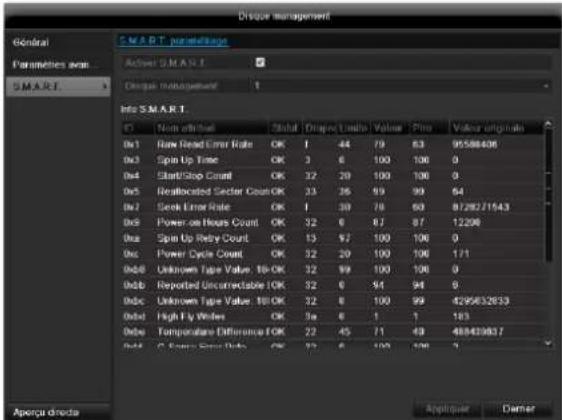
Specifications techniques
Common Intermediate Format
'PPP over Ethernet' (protocole Point-to-Point)
'Universal Serial Bus'
Udforelse at Standard 362
Netvark 362
Video Export 364
Normal 364
Haendelse (haendelsestype,Alarmindgang) 365
Installation at hardisken

Advarsel
IPv4 Address: 192.168.0.50
IPv4 Subnet Mask: 255.255.255.0
IPv4 Default Gateway: 192.168.0.1
Preferred DNS Server: 192.168.0.1

Henvisning
S.M.A.R.T. star for Self-Monitoring Analysis and Reporting Technology.
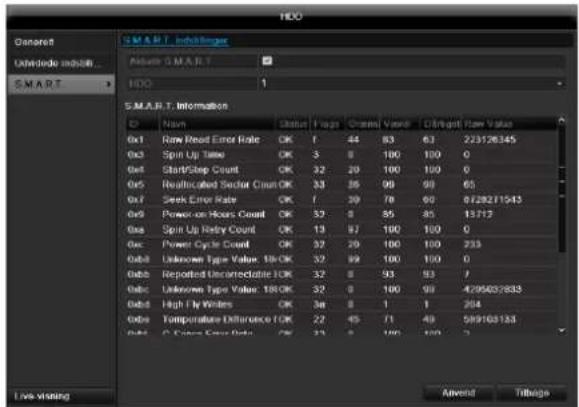
I donne undermenu vises informationer vedrorende harddiskstatus.
"Dynamic Host Configuration Protocol"
"Universal Serial Bus"
Seriel busforbindelse til tilslutning af f.eks. lagermedier i Iobende drift. Maks. anvendelig datarate ved USB 2.0: ca. 320 Mbit/s (ca. 40 MB/s).
HDMI/VGA
86444 Affing (Germany)
These user manual contains important information for installation and operation.
This should be also noted when this product is passed on to a third party.
Therefore look after these operating instructions for future reference!
A list of contents with the corresponding page number can be found in the index.
Français
S.M.A.R.T. to skrot z ang. Self-Monitoring Analysis and Reporting Technology.
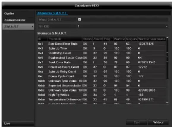
,Universal Serial Bus'
Hnctpykza no 3Kcnlyaataa
Bercsna 1.0
CE
Описиме пибopa
PepednnaHeJIb
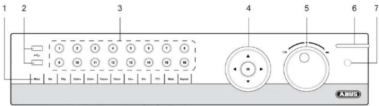
3aHnaHeIb
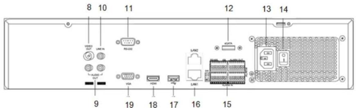
YnpaBJIeHne cncTeMoN O6uNe NOJoxKeHn
YnpabBneHnpe np6opom MOKet OcyueCTBJIaTbcr CJeDyUuM 06pa30m:
3JemeHTbI ynpabNeHnHa nepeDHe nAHeH np6opa
- NylbTynpaBneHn
USB-MbIWB
3IeMeHbI ynpaBHeHnHa np6ope
MecTo yCTaHOBKn/YcNoBnE KcNpyatau.. 453
IyIbT ynpabnien 454
Texnueckoe o6cnykubHne u xo.. 455
KoMnIeKryUoiue 455
BbD B 3KcPnyatauio 455
TeTn 455
BVeJeHne. 456
ObuaHΦopMaun 456
PacnaKobka 457
Obem noctabkn 457
Klambnatypa MoHntopa 458
BkIIOueHne np6bopa 458
BbIKIOueHHe, 6JOKIOPOBa, nepe3aRpy3ka np6opa. 458
OtpaxeHne cTaTuca. 459
Obuine noioxene. 459
CBeToIOIObI COCTOHN BnDeoperncTpaTopa: 459
KnaBn Bb6opa KaMepb CBeToOnoDb coCTOHN 459
HdkaHa MoHTope 459
Pomouzhnik Hactpoek 460
Hacrpoika cnCTembl 460
Hacrpoika AdmnnctpaTopa 460
CnCTeMHoe BpeMn data 460
Hacrpoikncetn 461
UnpaBneHne JeecTKm DnCKOM 461
Baxhna nHopmaun no ytnn3aun 6aTapei... .504
CcbIka Ha dIpeKTHBy EC RoHS. 504
Tloccapn 505
IcnoJIb3yEmble TepMnHbl 505
OBHyTpHHeM XecTkom DnCke 507
KpaTkaj nHcTpyKzna
IpepeI npBbIM nCNOJb3OBaHHeM
Hauana 3Kcnnyataun Heo6xOIMO npOBectn CneNyUyU noTROBky:
- CneyuTe 6OuM nOToXeHnA M, yKa3aHnA M no TexHnke 6e3oNaChOCTN, INcTpyKuIaM NO yCTaHOBKe N IOdkJIIOUeHnO, CM cTp. 24:
- IpoBepbTe coOpEpaHHe ynaKOBn Ha nonHoTy KOMPJIeKTAuN HAnuNe NOBpeXJeHn.
- BcTaBbTe 6aTapeN B nyIb T npabJeHnA.

Yka3aHne
CneyuTe yka3aHnMa B OTdEbnHO KnpaTko INCTpyKuIN.
YcTaHOBka XeCTKOrO DnCKa

PpeynpexdHne
BbIKHouHTe np6op n30npyte ero ot 3neKtpocet!
YHTe Heo6xOIMoe 3a3emHeHne dIy n36exAHn cTATnueckoro pa3pXKeHn.
- YctaHOBnTE ODNH INN HeCKOJIbKO JecCTKINX DNCKOB, CM. OTDeJIbHyIO KpaTKyIO INHCTpyKUNHO.
- Chaujana yctahOBITE coeINHeHne c rnaBHOI nlaToC nOmoBIO KpacHoro daTa-Ka6eJn (MaIbI uTekep).
3.ПодсоeДинITE ka6eJIb 3IeKTpOnIaHnA (6OJIbwoI wTekep,5-npoBODHOI). - IpoBepbTe WTeKepeHbI pa3bEm Ha npOuHOCTb/HaDeXKHOCTb NOKJIIOUeHnA.
- 3akpoTe Kopnyc.

Yka3aHne
NcnoB3yTe NCKIOUHTeNBHO XecTKne DNCKn, pa3peHHeIe IaBNeO3aIncn npab0TbIB KpyrNocTyOHm peKIMe 7DHeB HeJeIO.
IopknoueHne

Yka3aHne
YyTnTe MNHmAbHbI paDnyc npn npoklaKe Ka6eJIa! Ka6eJb He crn6aTb!
- CoeHHHe BCE IP-KaMEpbI c CeTbIO.
- CoeHHHe Bce DaTCHKn C TpeBxHbIMn BXOaAMN.
- Подклочи Te MOHITOP K HDMI/VGA- nIN BNCpa3beMy.
4.Подклочи Мьшь к pa3bemy USB. - Ipon3BeInTe ceTeBOe noKJIouChHeIe.
- BkIIOHTe np6Op c nOmoIbIO ceTeBOro BbIKIOHaTg «BbIKI.» Ha 3aDHe nAHeI np6Opa
Hnpeedne naneon OTo6pa3ntc cTaTyc peKIma pa60tby Bundeopernctpatopa.
KoHcHpyaun np6opa

Yka3aHne
CneyuTe yka3aHnMaB OTeJeNbHoN KpaTko INCTpyKcUN.
BbINOHNHe OTeJbHbIe WArN «POMOuHnKa HAcTpoEK》,CM. Ctp.33
BbIOJIHnTE KOHfIgpyaUIO CJeDyUOuNX HAcTpoEK B daHHoN NOcneIOBaTeNbHOCTN:
Bb6op 3bka noIb3OBeTbckOro nHTepceica
- HacTpoiKn AdmHnHcTpapota
- HacTpoNka BpeMeHn (data, BpeMra...)
- Hactpoyn cetn
- YnpabJIeHne XeCTKIM IINCKOM (yCTaHOBKn IN T.D.)
- Hac tropoKn 3aIncu

Yka3aHne
O3HaKOMbTeCb c INHΦOpMaquEn Ha caIte ABUS (www.abus.com) O haIInuHn nocIeDHHxO6HOBJIeHn BCTPoEHHoro npOrpaMMHoro 0eCeNeueHn IJa DaHHoro npIbopa n yctaHOBnte nx.

yka3aHne
PocneIyOuOe I3MeHEnIe DaTbI ININ BpeMeHN MOKeT npNBecTn K nOtepe daHHbIX!
- YUHTTE O63Op MEHIO Ctp. 41, yka3aHnI N ONCAHne OCHOBHORO O6CnyKbAHnCnCTeMbI Ctp.4.
O3HaKOMbTeCb c OnucaHne mpeXmOB:
MecTo yCTaHOBKn/YcNoBn3KcnIpyTaun
- YctaHOBHTe np6Op Ha TBepDoH,poBHOn IOBepxHocTn. He cTaBbTe Ha np6Op TJaKeJIbIe IpeDMeTbl.
- Pnp6op He npedHa3NaueH dIaKcnnyatauIN B NOMEeHnX C BbICOKoTempeatypoN IN BnaXHOCTbO BO3dyxa (HaNPmep, B BaHHoKOMHaTe) nN C 60JIbWHM CKONNeHnEM nbIIn.
- Temnepa type 3KcnjyaatauH IN BnaJXHOCTb BO3dyxa: -10°C Do 55°C, MACK. 85% OTHOCHTeHOB IN BnaJXHOCTN. 3Kcnjyaataua np6opa DOJXHa INPOIN3BOIDNTBCA TOJbKO BYMEpeHHOM KJIMMaTe.
CneJeTe 3a TEM, yTo6bI:
- Bcerda 6bIa oBecneueHa DocTaOuHnBa BeHTnlaCnna (He cTabTe np6Op Ha noIkn, TOnCTbI KOBep, Ha KPOBaTb NII B MeCTa, rDe BeHTnlaUHOHHbIE OTBepCTna 6ydyT npIKpbITbI, OCTabTe C KaXdoi CTOPHbI paCCToHnE MNHMym 10 cm;
B6n3n np6bopa He haoOpIOcB BO3deNCTByOuNX Ha Hero npMbx NCTOCHIKOB TENla (HaPnIMep, CNTem OTONHeH);
Ha np6op He naan npamO coJHbCBeT nnu CnIbHO NCKycCTBeHHoe OCBeueHne; - npu6op He haoDnncB H enocpeicTBeHHoN 6n3nOT MarHnTHbIX noJe (HaNPmep, rpoMkoROBOpntenei);
- ICTOUYHNIOTKpbIToro ORHn(HaNPIMep,rOpAUNe CBeu)He HaxoJINcB B6IIm3n pnp6opa JIn6o 6blnn paCNOJIOXeHbI HaD Hm;
- He donyckaIcKoHTaKT C 6pb3ramN I KaJIaMn BObl, a TAKKe arpeccBHBbIM NIKKOCTaMn;
B6JIN3N 3KcNpyaTnpyEmo np6opa He HaxOJIInCb KnIKoCTN.3anpeucaTc nprykaT np6Op B
KIOKOCTb (He CTaBBTe HaNOJIHHeHHbIe KIOKOCTMn IpeDMetbI PdOM C np6OpOM nnHa Hero: HanpImep, Ba3bl nn);
HeHaJIeKaIeE u HeKBaIINHcIupoBaHHOe BbIOnHeHne 3NeKTPnuecknx pa60u pa60T no yCTaHOBKe np6OpOB v DomaShNX ycNoBnX npEdCTabJIeT opacOCTb He TOnbKO dJa Bac, Ho n dJa DpyInx NiU.
CoeHnHe KaBeJem yCTaHOBHeHbIe np6Opbl, TaK YTObI CeT BbICOKOHaPRAKeHn I cEInb HN3KOHO HApRAKeHn 6bln IpOLOKeHb OTeJeBHO dpyr ot Dpyra, He nepeceKaINc bnn He MOrn npeceuebc B CJIeDCTBne DeΦekTa.
#
3NeKtpueckne np6opbl He npedHa3HaueHb IJnI deTei! He octabnIte DeTei nOlb3OBaTbcI 3NeKtpueckmnp6opam6 6e3 npcMoTpa. JeTu MOryT He OCO3HaTB Bo3MOxHOn ONaCHOCTn. MeIKNe DeTaNn ppr nporlaTbBAHN MoYr 6bITb KIN3Heonacbl.
XpaHnTe 6bapen n aKKyMnyTOpbI B HeNoctynHom dnn MaNeHbKnx DeTee MeCTe. Pp npOrnaTbHaHn 6bapen nn aKKymyTopa Heo6xOIMO HEmdneHHo 6paTntbcra 3a MeDnUHCKoN NOMOuBIO.
XpaHnTe ynaKOBouHyIO nIeHky TaK JKe B HeIOCTyINHom IIna DeTe N MeCTe. Bo3MoXHO ydyuweHne!
-Данн布局прбор He npedha3haeHдЯ DeTei. Пужинсты Детаи ри HeHaJnEkaшemnpIMeHmMOryT BbICaKbBaTи npuHHTb DeTAMnoBpeXdEHn(HanpIMep,dЯ rna3).
BVeDene
Ybaxaemblie KJneHtbl!
Mby 6laorodapm Bac 3a npno6peTHe daHHoro npoDyKta.
AaHHbI npOyKT COOTBETCTBye Tpe6oBaHnM DeiCTByIOUx EBponecknx HauNoHaJIbHbIX DInpeKTNB.
COOTBETCTBNE yCTAHOBJHeO, COOTBeTCTByHouIe
Deknapaun IN DOKyMeHTbI PpeCTaBJIeHbI
Pon3BODnteIeM (www.abus.com).
Дя coхраеня данно обтояпьства.
obecneueHn 6e3onachoN ekcnnyataun Bb KaK
Ponb3OBaTeB o6raHbI cO6JIIOdaTb daHHyIO
HnCTpyKcNIO!
Ipeed npimHeHHem npOdykTa 03HaKOMbTecb C nonHOn HnCTpyKcnei, o6paTnTE BHMaHne Ha yKa3aHna No kCpNlyatauIN n TexHnke 6e3oNaCHOctn!
Bce Ha3BaHnIaΦnM I npOyKTOB YBnIOTc TOPROBbIMN MapkAmu COoTBeTCTByUoIero BnaJeNbua. Bce npaba 3aunuHebl.
Ecny Bac Bo3HKnBOpocbl,obpaTntecb K BaWeMy cneuaancty no MOHTaxy nn Dnepy no cneuainnpOBAHHbIM npoJaXaM.

NCKIIOUeHne OTBETCTBEHHOCTn
DaHHa HnCTpyKuJa No 3KcNpIyatauHbIM 6bla coCTabHeHa cMbIM TuaTeJIbHbIM 06pa3OM. B clyuae, ecnB bI 3amEtUIn ynyuEHHa nn HeTOUHOCTn, COo6uNTe HAM O HIX B NcBMeHHoJ FOpe Me no aDpeCy, yKa3AHHomy Ha o6paTHoI CTOpOHe pyKoBOdCTBa. KomnaHnA BUS Security-Center GmbH & Co. KG He Hecet OTBeTCTBeHHOCtB 3a TeXnueckne n TINORpaΦmueckne OUsbKIn N OCTaBnAET 3a Co6oB npABo B IIObO Momet BVpeMeHN BHocHTb N3MeHeHnB POnyKT INHCTpyKuIN NO 3KcNpIyatauN 6e3 npEdBaPntbHoro npEynpexJeHn. KomnaHnA BUS SecurityCenter GmbH & Co. KG He Hecet OTBeTCTBeHHOCtN 3a Bo3HnKUnB pe3yIbTaTe npraMoN KOCBeHHbY uep6 B CBa3N C OChauneHem, KaueCTBOM pa60TbI npImeHnEM DaHHOro npOdykTa. KomnaHnHe npedOctaBJIeT HnKaOKI rapaHTn Ha coDEpkHHe DaHHORO DOKymeHTa.
06zaHΦopMaucn
B ueJx npaBnIbHOJ 3KcNpyatauHn np6opa BHNMaTeJIbHO IpoUHTte N O3HaKOMbTEcB C PykoBoDCTBOM IOpIb3ObaTeJIa, a TAKKe coXpaHnte erO dJaIbHeJWeO nIb3ObaHn.
JaHoe PykoBoCTBO copeKHT yka3aHnno 3KcnpnyatauHH TeXo6cnykBaHHo peHnctpaTopa.
YBeDombTe o pemOnTe np6opa cneuaIbHyIO fnpMy, IMeIoUyO pa3peSeHHe.
PacnaKOBka
Bo BpempaNakOBKn 6paauaTebc npu6opom c oOc0n octOpoxKHOCTbIO.
YnaKOBka n BCnOMOraTeNbHbIe yNaKOBOUHbIe cpeDCTBa npiroDhbI dIy tYNIIN3aUN pncaiKNIHROM, a TaKKe dIa DOnOJIHNTEbHorO NcONb3OBaHra.
Mbl pekomehnyem:
Ipon3BODntb yTnIn3aun6yMaH, KapToHa I roopnpoBaHHoro KapToHa nII nn pnaCTNKOBY npakOBKn B npedHa3NaueHHbIX dJIg 3TOr KOHTeHepax.
EcnTakOBbIe OTCyTCTByOT B MeCTe BaJero npOxINBaHn, daHHbIe MaTePnaJIbI MOrYT yTNJIN3NpOBaTcBMeCTe C 6blTOBbIMN OTXODAMN.
PnB03MOXHOM NOBpeKdEHHOpnHnHaJIbHOyIaKOBKn Heo6xOdmo cHaJana npOBepntb np6op. B cnlyae ycTaHOBJeHHN NOBpeKdEHH np6opa oToWnnte
yKa3aHne
Приип Te BO BHMaHne,чTo ДЯданHoro BndeoprrctpaTopa nporpamMhIe n3MeHeHnДолЖы ПОТВерждatabc c NOMOь UцELHka «ПриMuHnTB》/«ПОТВерДИТь»,npexJe Yem Bbl POKHHeTe BKJaKу Ил MeHIO.
Pp6op C ynaKOBKOI o6paTHO N CBxNTEcB C Ppon3BOOnTeJIem.
ObemIOCTaBKn
32-x KaHaJIbHbI cTeBOB BnDeOpErncTpApTOp ABUS
CeteboKa6eb
- SATA-Ka6eJIn N BnHTbI JIJI KecTKnX DnCKOB
Kpenenne n BnHTbI dna cepBepHoro Wkaq
- Dnck CD
-PykoBoDCTBO Nolb3ObaTeJra
CoeINHtJIbHbIe KIeMMbl
KpaTkoe pyKoBOdCTBO
KnaBnataPmaOHToPa
PnIeNKeMbIKoNIO NOIIO BBOa TEKCTa NOBNTcKNaBnAtypa MOHToPA:

Pn BBeDHN TOJbKO YIcE N NOBNTC R CNeDyUoa JIaBNaTpya MOHITopa:

KnaBnHmEOTyHKuN,ndeHTnUHbIe KnaBnAtype KOMNbIOTepa.
- BBeHeHn3HaKa ⅢeKHTe No Hemy JneBOI KHOKNOMblu.
-Дязавершенивбда нахмITEHaEnter.
-Дя удаленя 3нaka nepeД kypcopom Haxmnte Ha.
-Дяпегкюченma经у 3aflanbHbIM n cTpoUhbIM HANICAHm, ueJKNHTe Ha a B pAMKe. AKTNBHaHACTPOIka OTo6pa3ntbC8cBepxY KlaBnAtypbl. - UTo6bI npeKpaTb BBOJ N NOKHHTb NOne, IeJIKNHTE ESC.
BkIoueHne np6opa

BhimaHne!
Pn6op MoKet 6bItb NpKnIoueH K yka3aHHOMy Ha 3aBOcko Ta5nUKe HapRaeHIO ceTu!
Дябз�аCHOCTI npIMeHЯTe 6ecpepeBoHoe nHTaHne IVI.
Ipi npokknoeHnn np6opak nctOCHky nntAHnB KIOUeHHOM rnaBHOM BbIKIOuateJe Ha 3aHeN paHeJI np6opacBETNCBcTeODnOd coCToHnBnDeOpErncTpaTopa.
1.BoBpem3anycka npnbop npoBoNT camonpoBepky.
2. ПО OKOHuaHn KOTOpOI NOBJIeTcI NOMOuHnK HAcTpoE.K.3aKpOInTe erO, YTo6bI nepeHTN K IpocMToTy.
BbIKIIOUeHHe, 6IOKIpOBKa, nepe3arpy3Ka np6opa
UeJIKNHTe B IJIaBHOM MeHIO BbIKIIOHTb. IOnBNTcra 063Op.
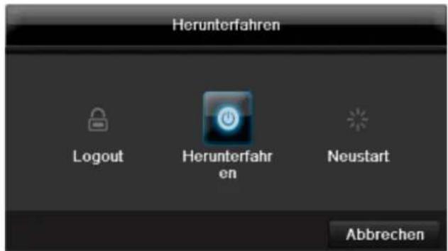
1.ДЯВIKHNoeHnBbI6epnteOnuIO BbIKHNoHTbN noDTBepeNTe3anpoc,HaxaB Da.Ipn6Op 6yJeT BBIKHNoeH.
Bo Bpem npoecca BbIKIOueHnHaHXmaiTe KnaBnSi
2.ДЯ6LOKINPOBKN CNTeMbI BbIbepnTe CmBOJ CJIeBa 6LOKINPOBAtb.ПОЛьЗOBaTEЛьСКИ NHTePcEInC TeNep3a6LOKINPOBaH.YTO6bl nonactb B MeHIO Heo6xOIMO BBecTn napoiB.
3.ДЯПepe3arpy3knHaxmnteCnMBOJcnpaBaIpe3arpy3ka.ByTe npOn3BeDeHaPpe3arpy3ka np6opa.
BkHoueHne np6opa
HaxmTe KnaBnUy OK n ydepxnBaHTe HaxaToB TeueHne 5ceKHy dIra HOBO BKnIOyeHn np6opa.
Отразхенистуca
06uhe noJoxeHHa
Cneyuouee otpaKeHne cTaTyca npOnHΦopMnpyT Baco pa6oem coCTOHN np6opa:
- CBeToIIObI Ha nepeDHeI nAHeI np6Opa
- Akcytneckne cnHnabbl
- RaPbIKn (3JIeMeHTbI INHdNkauu) Ha MOHHTope.
yKa3aHne
CneyuTe yka3aHnMaB OTeJeBHO KnpaTko INCTpyKuIN.
CBeToIIOIbI COCTOHaHnBnDeOpErNcTpaTopa:
DMVGA-MOHumOp He noDknOyuH:
Ecn npn 3anycke HDMI/VGA-Ka6eNb He noKnHueh K MoHtOpy, rnaBbHn BnDeocnHaB bBbOJNTcH a pa3bem BNC Main. NpKnHouNte HDMI/VGA-Ka6eNb n nepe3anyCTne perncTpaTop dnn BbINOnHeHn ABTomAtYeCKOro pacno3HaBaHn.
HactpoKa BbIXOa KaMepbI
BbMOKeTe IpON3BOOnTb BOCpON3BeJeHne OJHObpemHeMoK. No 32 KaMepam (TVVR45030) BpeXmE OTo6paXeHnA.
Pn nCnoJb3ObaHnn poyTepa cTeBbIe KJIneHTbl, a TaKKe peRnCTpaTOp, NODKJIIOUaOTcK INTHepHety. HAObOpOT. Bo n36ExaHne HecaHKUHOHnpOBaHHoro DocTyna n3BHe o6raTeNbHO npIMnTe 3aUInThbIe Mepbl, nCNoJb3y, HApnPmEp, 6paHdMayp, INMeHja napOl b I nopTb!
KoHpyauncaTn
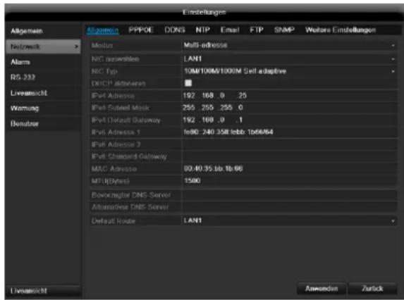
Ionb3oBaTeJIb MoKeT C NOMOuBcTeBOrO coeunHeHnna NoynuHTb DoCTyn K npBOpy.
Bo BknaJke «Kamepa» HactpaunBaHOTc npaba IJnIOCTyNA KOTdJIbHbIM KamepaM (Yepe3 cetb INI JOKaJIbHO).
NOMOUIIO NOIb3OBaTeJIbCKNX HAcTpoEK B COOTBETCTBNCOCBEUeHnEM.
PTZ

Yka3aHne
3decb moKHO yCTaHOBnTb PpeDyCTaHOBky n Patpynn dny IP kamep TVIP2xxxx.
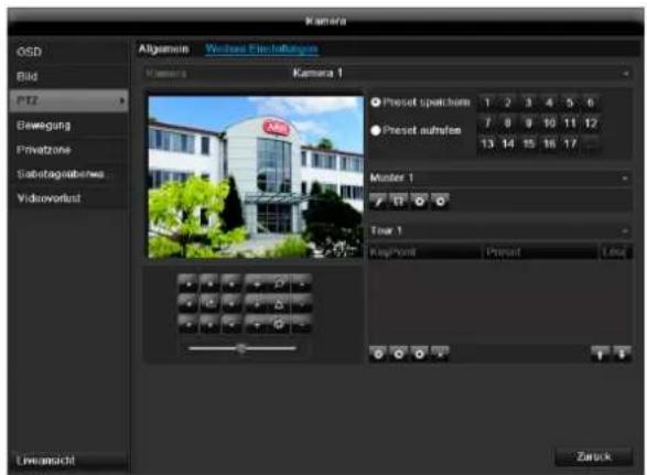
CoxpaHeHne N Bbl3OB npeDyctaHOBKn
- C nOMOuI KJIaBnU-CTpeJOK IP kAmepbI yCTaHOBnte XeJIaEMbI ΦparmEHT N3O6paXeHnI N COxpaHNTe I03NcHIO, HAnpIMep, KaK npedyctaHOBka 1.
- Μεπκητe Bb3BaTbДЯ Bb3Oba coxpaHHeHoi npedyctaHOBKn 1.
YcTaHOBka N Bbl3OB NaTppyJe
AknBaunKaHana(Tonbko npn DTeKTope DvXKeHn):
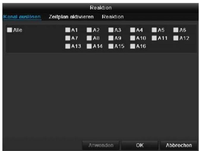
Bb6epnte OINH INH HeCKoNbKO KaHaNoB, KOToPbIe B cnUyae TpeBOrn DOJXHbI AKTNBupObaTb DeiCTBne. IOnTBepNTe HAcTPOuKN, UeIKHyB PpIMHeHTb N OOKHBTe MeHIO, HaxKaB OK.
PacnncanHe
BbIepeTe BkJaDky PacncaHne.
YCTAHOBNTB KAKOE BpEMHaCTPOEHHbE B BKnAKe DeCTBneDeIeCTBnI DOJXHbI 6bITb aKTNBnPOBaHbI.
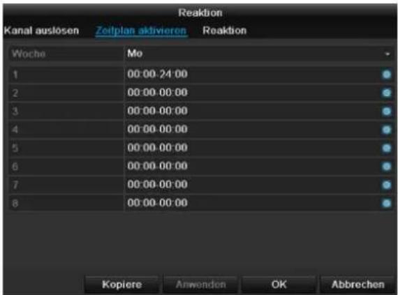
- BbIbepuTe DeHb I yCtahOBuTe paCnncaHne.

Yka3aHne
MaKcMaJIbHO MoXHo yCTaHOBnTb 8 BpeMeHHbIX ceToK, KaXdA c 00:00 -do 00:00; BpeMeHHbIe OTpe3Kn B OTeJIbHbIX BpeMeHHbIX ceTKax He DoJNXHb I nepeceKaTbcra.
- BbIePeNTe B KonnpoBaTb,doJxHa IIN HAcTppoKa npImeHrTbcra KO BCEM dHram HeJeN IN HAcTppoKam OTnycKa.
- IoTBePnte HAcTpoKn, UeJKNHyB PnpMeHHTb N OOKHBTe MeHIO, HaxKaB OK.
DcCTBnE
Bb6epnte BkJaDky DeIcTBe.
3decb MOxHO HAcTpOHTb NOBeHHe peRNCtpaTopa BCnyae ONpeDeHnHO Co6bITn (HanpImep, npi DeTeKTope DmXeHn), yCTAHOBnB COOTBeTCTByIOuNn fnaKoK.
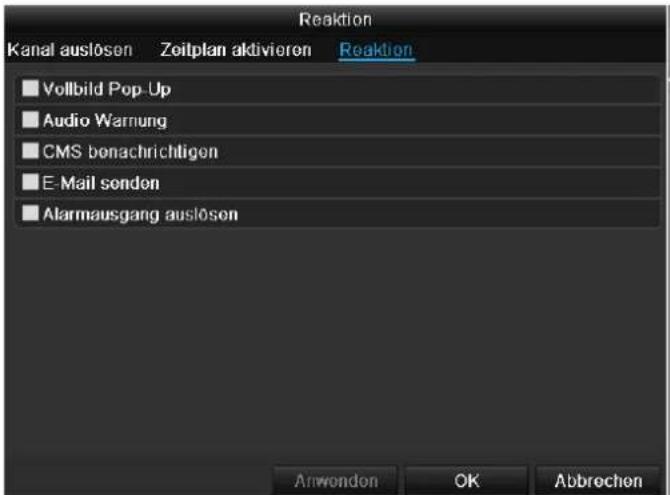
Ecnn JecTkni Dnck He OTo6paKaetcra, npOBepbTe coeDInHeHne.
Bb6epnte MeHIO «HDD»ДЯ yctaHOBJENHaHCTpoek ynpabJIeHnJXeCTKIM DNCKOM.
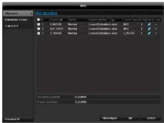
IapametpbI ynpaBHeHЯ JecTKM DnCKOM
CocToHHe JecTkoI DnCKa MoXHO pOBePHTB MeHIO
《Texo6cnyKuBaHne》.B nor-phiJax coxpaHaeTcra
HHopMaunr no TexHoJorMn SMART (Self-Monitoring,
Analysis and Reporting Technology).
ДялготоуOTKpoIteIor-ФaIиВыINJIHHTeПОИС ИФOPMaU/S.M.A.R.T.ЖecTKnДИСК.CM.CTp.Fehler!Textmarke nicht definiert..
HactpoKn TpeBOrn XecTKoro Dncka
3decb moKHO 3aDaBaTb CnHaJIbI npEynpeJxHEny JXecTKoro DNCKA, KOToPbIe 6yDyT COo6uAtb 06 Own6kax XecTKoro DNCKA.
-ДязTORO OTKpoIte pyHKT «Texo6cnyKuBaHne» B MeHIO HAcTpoeK.
Bocnpo3BeDeHne
Bb6epnte BrrnBHom MeHIO HAcTpoKu 3aTeM BocnpOn3BeDeHne IJI NaCKa BnDeo3aPiNcEi No CO6bTIHIO IINI apJIbIKy IINI dJI npOCMOtpa COxpaHeHHbIX N3O6paxKeHNI.
PpOdoJXHTeJIbHocTb
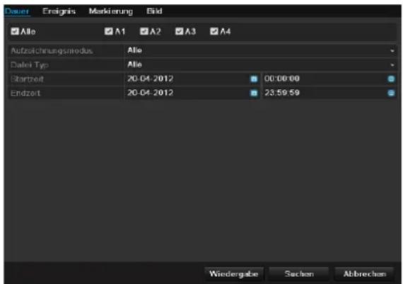
Cneyuounie Hactpoikn Moryt 6bItb BblpaHbI:
KoHpIpynpoBaTb np6Op.
06HOBJIeHHe
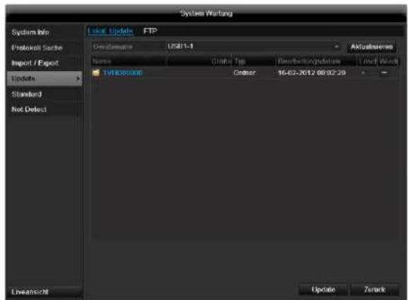
i yka3aHne
OboBHeHne np6OpOB MoKet npOn3BOuNTbcra c nOMoUb USB-cpeCTBa yepe3 ceTb FTP.
- CkOnnpyTe paAnO6HOBneHnC pacuHpeHem*.cap Ha USB-ΦneUky B rJaNBHy cNcOK.
-
Pooknoute USB-ΦneuKy K USB-pa3bemy Ha npnbope.
-
BbI6epnte USB-pa3bem, ueJIKNHyB npn Heo6xOAnMoCTN AkTyAIn3uPoBaTb.
- Bb6epTe paHn 06HOBHeHna, 9eKHyB O6HOBHeHne.
- Поождп Te noka npu6op He npou3BedeT nepe3arpy3ky.
- Поберпс coctoryн e BCTpoeHHOro nporpaMMHOrO 6eCneueHn B MeHIO Texo6cnyxuBaHn e nD InhfoMaCuNe.
i
Yka3aHne
- 06HOBHeHne uepe3 FTP npoicxoDnT kak OncaHO BbIe: PIKdoJIkeH haoDnTbcB ToJ Xe JOKaJIbHoN cETn.
- YctaHOBnTE IKN B KaueCTBe FTP- cepbepa.
BVeInTe IP-aDpec FTP-cepBepa.
Pon3BecTH BOCCTaHOBJeHne CnCTembl
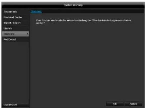
i
Yka3aHne
Pn daHHom npoecce hactpoyn np6opa n3MeHIOCTc Ha 3aBOckne (BocctAHOBNeHne).

PpeynpeKdHne
Bce HacptpoK, KOtOpbIe Bby yCTaHOBUN C MOMeHTa NcKa B 3KcNJIyatauHO (kamepbI, HAcTpoKn 3annci, PTZ, TpeBora n T.D.) 6ydyT ydaJeHb!
PpeoTbpaTne notepO daHHbIX, coXpaHNB HactpoKn. IIO OKOHuaHN IpEydCTaHOBKn Bbl MOKeTe CHOBa CHTaTb IX.
Cetb
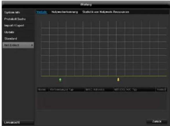
i
Yka3aHne
3decb OTo6paXaetc HOpMaun O CeTeBOM DBHXeHN NHTepceence.
Bknadka cTeBaHaHarpy3Ka
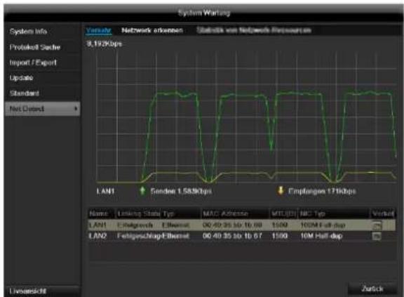
KoJIueCTBO noJyueHHbIX npHnAeHHbIX OtpaKaetc rpaHneckn.
B noJIe nOД rpaФИKOM B 3aBnCIMOCtN OT CeTeBbIX HacTpoE KOTpAkaETc COCTOHne N INΦOpMaunr O6 OdHOM, DBYxCeTeBbIX pa3beMax.
BknaKa PaCno3HaHne cTeN
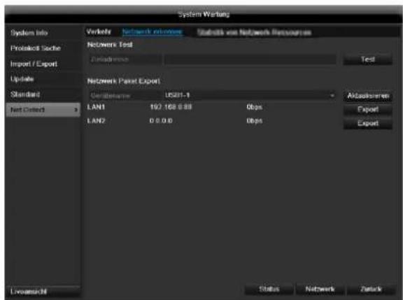
В «Задерхка сети» Вы можеTe («проннговать»)npOBeRtB coeДиЕнHeC dpyrIM np6OpOM,HaNPmEpKoMnIbIOTepOM.BBeДITE cETeBOI aDPEC npOBepReMOrO np6Opa (HanpUmep 192.168.0.25)ИнжмITE npOBePka.
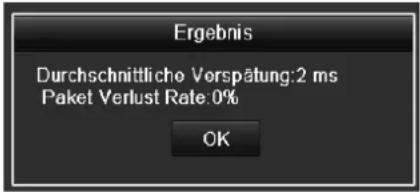
HOpmaIOnO DByN npaMetpax OTo6paKaetc:
BknaKa CtaTnCTnKa ceTeBbIx pecypcoB
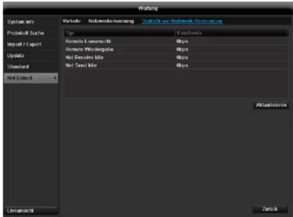
B daHno BknaDke OtpaKaetcNcNoJb3yEmble ceTeBbIe pecypcbI yctpoiCTBa.
UeKHyB NO AkTyAn3npoBaTb MOxHO 6HOBuTb daHHble.
Pe3epB. Konnya
PpOdoJXHTeJIbHocTb
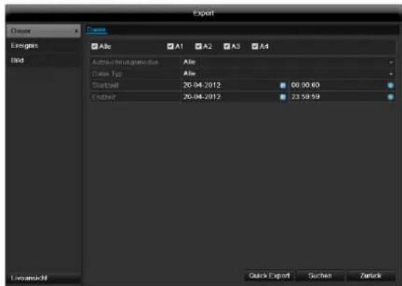
yKa3aHne
Функця pe3epBHOJ KOJIIN COXpaHЯET BaxKhIe 3aIIncn Ha NOdKJIIOUeHHbIX BHeuHNx HocHTeJIax, HapPIMep:
HocnteJx USB
USBKecTKnxDnckax
- yctpoinCTB dIJI 3aIIncn DVD n T.D.
C NOMOuBHO 《3KcnpT] npoN3BOHNTc8 3KcnpT BCex 3aHnCe BbIbpaHHOrO nepNoDa BpemeH. Pn3ToM Heo6xOJMo yueCTb, YTO MaKc. MoXHO 3KcnpTupOBaTB 24 yaca 3aHnCn.
YcTpaHHeHHeNcPpABHOCTeI
Ipeed Bb3OBOM CepBnCHoCnyK6bl npOHTTe cJeDyUoNue yKa3aHnNo OnpedeJIeHIO BO3MOXHO npuHbHeNCpabHocTn.
CyueCTbyeT Bo3MOXHOCbI NOKNUeHn DOnONHtBHoro Spot-MOHHTopa. Bb6epnte B HnKeepuBedeHHo Ta6NHe BO3MOXHbIE KOM6NaUH. IaNoUka O3Haayet BO3MOxHO, Kpct - HeCOBMeCTMIO.
| HDMI: + VGA | HDMI: + CVBS | VGA + CVBS | HDMI: TOЛьКО | VGA TOЛьКО | CVBS TOЛьКО |
| ✓ | ✓ | ✓ | ✓ | ✓ | ✓ |
yTnIIN3aun
CcbIka Ha dIpuKeTnBy EC no yTuJn3aun cTaporo 3JeKtpnueckoro n 3JeKtpoHnOro o6OpydoBaHna.
B cBra3n C oxpaoH OOKpykaHooe CpeDb np6op nO OKOHuaHn Cpoka ero Cnyk6bIMoKet 6bITb yTuIN3OBaH OTJeIbHOOT 6bITOBbIX OTXODOB. YTuIN3aunr MoKet OcUeCTBnTbcr Chepe3 OPhiuaJIbHbIe NyHKtbl npHeMa B BaWe CTpaHe. Co6IouaTe MeCThBi e npEiNcaHn rno yTuIN3aun MATEpnaIOB.

ПюиЗБeДTe yтлИзацию устpoиCTBa corlacho dinpeктNBe 2002/96/EC - WEEE (Waste Electrical and Electronic Equipment) no ytлИзaци nOxOДOB 3ЛЕКТпчесКOrO n эЛЕКТрОнHOrO obopydOBAHnY. EcIn y Bac Bo3нIKЛ BONpOsbl, obpaTnteCb B MeCThIbe opraHbI ynpaBJIeHnY. BoJee npIoPo6HyIO INФopMaциЮ O pyHKTax ппema CTaporo obopydOBAHnry Bbl nOpyHTe B MeCThIbIX opraHax ynpaBJIeHnY, MeCThIbIX ytлИзИруQUx KOMпАнЯx ИПи y Baшero dInJIepa.
Yka3aHnno o6paueHnIO c 6aTapeaMn
BctabIyIte 6aTapeu cornacho nx noJIocCy,He nbITaNTEcB CHOBA 3apAINb NOCTabIYeMbIE COBMecTHO 6aTapeu Hn npKaknx 06ToTeJbCTbax He 6pOcaIe INx B OTPbITbIe nTOUHNkOrHr. Henb3ry NcNoJIb3OBaTb ODHOBpeMeHNO pa3HbIe 6aTapeu (CTapbIe u HOBbIe, anKaJIHOBbIe uYrIepoNbIe). BbIHbTe 6aTapeu, ecnn yCTpOoiCTBO He NCNoJIb3yETc DOJIroE BpEm. Ppi HeHaNDexKaUem NCNoJIb3OBAHm BO3HNIkaeT onachOCTb B3pbIBa N bItKeHnra!
- Πο3a6oTbTeCb o 3aUHTe npuPoIy! IcNoIb3OBAHHbIe 6aTapeH Heo6xOДmO yTuIN3OBaTb OTdEJIbHO OT 6bITOBbIX OTxOIOB. Heo6xOДmO cdaTb INX B NyHKT npHema cTapbIX 6aTapei.
CneIte 3a TeM, yTo6bI 6aTapeH He nonanB pykn DeTAM. DeTu MOryt nIoXnITb 6aTapeu B pot IN nporJIOITb ux. 3TO MOKeT npuHnHTb BpeD 3dOpOBbIO. B noo6Hom cIyuae Heo6xOIMO o6paNTbcK BpaUy!
- 06bUHbIe 6bTapeH He pa3peWaaETc3aPjXaTb, HarpeBaTb HnN 6pocatb B oroHb (OnachOcTb B3pbIbA!)
- Bobpem3aMeHnTe 6aTapeu.
Bcerda npoun3BODnTE OndHOBpeMeHHy 3aMeHy Bcex 6atapeu n uCnoNb3yNe 6atapeu OndHoro Tuna.

Baxhna nHΦopMaun!
3apxehhhe iINIOBpeKdeHHbe 6aTape npn COpIKoCHOBeHN C KOKeMOryT npuHHTb OKOHN.
IcnoJIb3yIteBdAnHOMcIyuae
COOTBETCTBYOUINE 3aUHTHBIE NEPuATKn.
OuHCTnTe rHe3do 6aTapei cyxoi caIΦeTKoI.
Baxnay nHopmaun no ytnnn3aun 6atapei!
Дяданноги рpoуктапименгсбаарe, yTIN3aця KOTOpbIX npON3BOJNTcB COOTBEcTBnC eBPoneckoi DupeKTHOB 2006/66/EC ndoJXHa npON3BOJtbcra OTdEJIbHO OT yTIN3aци 6bITOBbIX OTXODOB.
IOnyUHTe HnΦopMaζHIO O DeIcTBHyOuX HOpMax B BaWeI cTpaHe o pa3dJIbHOYtUNN3aζM6aTapei.
IpaBnBHa yTuIN3aun6batapecnocobcByeT npedOTBpaueHIO OTPuataTeJbHO BO3dEICTBna Ha OKpykaiouyo cpey u 3doPObbe.
DaHHbIe CmBBoJIb pa3MeUeHbI Ha 6aTapeJx c CoepKaHnEM BpeHbIX BeueCTB:
Pb = 6atapera c coepkaHnem CBNHua
Cd = 6aTapeC copeKahnem KaDMNIA
Hg = 6aTapec coepkaHne m pTyTN
CcbIka Ha dIpuKeTnBy EC RoHS
Pn6bOp cooTBeCTByeT dIpeKtInBe RoHS.
CobnOeHne DnpeKtNBbIC RoHS 03Haayet, YTO npOdyKT Nnn DeTaNb CopeKNT BeueCTBa, DOnJ KOHcHTpaunN KOTOpBIX BROMeHHbIX MaTePnAnax He npEByIaETMakCmMaJIbHO DonyCTMbI yPoBeH. NHaue, daHHoe BeueCTBO NCKIIouyeHo n3 DnpeKtNBbI RoHS.
a) 0,1% CBNHua (B 3aBNCMOCTN OT Beca),
b) pT Tb,
c)JeeCTNbAeHTHbI XpOM,
d) noIIN6pOMnPOBaHHb 6nΦeHN n noIIN6pOMnPOBaHHb DnΦeHNIOBb 3Φnp,
e) 0.01% kaДмья (В 3aBиСmOCTN OT Beca).
Tloccapn
IcnoJIb3yeMbIe TepMnHbI
1080P:
HDTV-BuDeocnHan c 1080 nKcIaMn nporpeccNBbIM npOCMTpOM.
16:9
KInHoOpnEHTnpOBaHHoe COOTHOWeHne CTOpOH WInpOKo3KpaHHoro DnCnIe.
DnaorohJIb n3o6paKeHHa
YKa3aHne pa3Mepa DnCJIe: pacCToRHe MExd YIeBbIM HIXHM IN IpaBbIM BepXHM yTlOM - B DIOImax NIN caHTmEpax.
6pay3ep
Pporpamma nla npocmotpa Be6-caTob B cetn INHTepHET.
CIF
«Common Intermediate Format».
N3haaIbHo npedHa3HaJcraI JnpeB0da fopMaTa PAL B NTSC cTaNdapr. CIF COOTBeTCTByET BVdeOp a3peWeHIO 352 x 288 nKceJe, 2 CIF 704 x 288 nKceJe, 4 CIF 704 x 576 nKceJe.
CINCH
PacnpoctpaHbI Tn aHaNoROBbIX aydno IN BundeOcRHaJIOB FBAS.
DDNS
ДиhamуескDN
CeteboepeBnC,coepkaunIP-apecaKnneHToB B 6a3e daHHbIX n pOIN3BOJauu nn O6HOBHeHne.
DHCP
«Dynamic Host Configuration Protocol» - npotoKoN DInHaMnueckoHacTpOKn y3Ja
CetEBo npOTOKOJ, NO3BOJIAUHm ABTomATnueckn HHTerpnpOBaTb yCTpoiCTBa (KIneHTbl) B cyuEcTByIOUne cETn. Pn 3tOM cepBep DHCP (HanpImep INHTpeHETPOyTeP) ABtomATnueckn npcBAunBaET IP-aDpeca, Macky cETn, uH03, cepBep DNS nHn cepBep WINS. Co CTOPOhbl KIneHTa Heo6XoHm aKTINBaun aBTOMatnueckoI IOnyehn I-PaDpeca.
Домен
IbpiHbBn BnDeoperncTpaTOp, BnDeoperncTpaTOp dna 3aNcC NOMOu bO aHaIoroBbIX n CeTeBbIX KaMep.
http
«Hypertext Transfer Protokoll» npotoKoI nepeaun rInneptekcta.
Ppoeepeepaun daHbix yeep3 cetn. PpmeHaeTcB OCHOBHom npan pocmotpa caHTOB INHTepHeT- 6pay3epe.
Upeecctpouha pa3BepTka
MeToD TeNeBn3NoHHo pa3BepTKn.
IP-Adpec
Adesc B KOMnbIOTePhoN cTeH. Ochoban Ha Internet Protocol (IP),KOTOpBn IpiNCBaNABaET cTeEBIM ycTpoiCTbAM ONpeJeHHeHbIe aApca n, TaKIM o6pa3OM, DeJaet IX DOCTyINHbIM.
JPEG
Ipocecc KOMPecCn DnA FOToRpaΦn C MaJIbIMn nOtepAm. BoNbUnHcTBo UΦpoBbIX KaMep coXpaHrOT FOToRpaΦn BΦopMaTe JPEG.
MPEG
CokpaunenepnMoving Picture Experts Group.
MekdynapoHbI cTaNapr InKOMPecCn uΦpOBoN, BnDeo n ayDnO nHΦopMaun. Ha HeKOToPbIX DVD KOMPnIMPoBAHHbI n 3aNcAhl uΦpOBbIe ayDnOCnHaJIbI daHHOΦopMaTa.
NTP
«Network Time Protocol»
IpoceccnHxponHaun yacOB uepe3 INHTepHeT-ceTN.A
TaKkeSNTP (Simple Network Time Protokoll),
npedctablaioi 6oee ynpoeHHy0 fOpMy.
NTSC
CTaHdApTHa CnCTema CBETHO TTeBUNeHn B CUSA.
IMeet HeKOTOpbIe OTNnUHr OT EBPOneCKoN CnCTembl PAL.KaIp NTSC coCTOHT Bcero n3 525 cTPOK,480 n3 KOtOpbIX BnIMbIe.B CekyNDy OtpaxaHOTcR 60
n3o6paXeHn CtepeONapbl. IOn CpabHeHIO c PAL
CnCTema B 6oJIbWei CTePeHn NOdBepKeHa LBeTOBOMy
nCKaXeHIO.
PAL
"Picture in Picture"
CokpaueHne IJnФyHKuIN «N3o6paxeHnB N3o6paxeHn》,6laOapra KOTopoHa 3KpaHe OHObpeMeHHO NOBnIOTcDA Ba nCTOHTHcNA CnHAnOB. BTOPO INCTOHTNK CnHana HknaDbIbAetc Ha nepBbI.
PPPoE
«PPP over Ethernet» (Point-toPoint-Protokoll)
Ppoecnpeepaun daHHbIX uepe3 cetb, nCNoNb3yeTcnn yCTaHOBHeHn COeHNHeHn C Bbl6paHHbIMn COeHNHeHnMn, KOtOpIe HapnpMEp nCNOlb3yOTc npn ADSL-noKluOeHn.
PporpeccnBna pa3BepTka
OTo6paXeHne n3o6paXeHn, npn KOTOpom pOncxOaNT PocNeIOBaTeJIbHoe OTo6paXeHne BCex CToPcK KaIpa B IpoTNUBOBeC uepeccToUHoi pa3BepTke.
PTZ
Пановамиpoване,нaklioн,уBELИчЕнeДЯ MOTOPИЗЮВаHHbIX KAMep.
RTSP
"Real Time Streaming Protocol, RTSP"
CeteBOn npToKoJ dny ynpaBneHn noCToHHoN nepeDauey nToKa nn nporpaMMamu uee3 IP-6a3npoBaHHbIe cTeN.
SNMP
«Simple Network Management Protocol»
Cetebon npotokon, kotopb pyerynpye T coo6ueneMekdy Ha6nOdaembIMN yCTpOINCTBAMN u CEHTPOMHa6nOdeHNA. C COOTBeTCTBYUQNM pporpaMMbIM o6ecneHMe MOKeT NcNoB3OBaTBcRdIa Ha6nOdeHNA 3a CTaTycOM BnDeOpErNCtpaun.
USB
Universal Serial Bus
CepnHoe coeINHeHne sIHc pa3bEmOM, HapnpMep c HocnteJIaMn daHHbIX, BO Bpem TaKUeN 3KcNlyaTaun. MAcC. nCNoB3yEmbI o6bEm daHHbIX y USB 2.0: npm. 320 M6nt/c (npm. 40 MB/c).
VGA
OBHHTpeHHem XeCTKOM INCKe
BHyTpEHnJXeCTKnI DnCK (HDD) CyBCTBnTeJIeH K n3MeHeHnM. Ipn3BOAnTe ynpabHeHn YcTPOINCTBOM B COOTBeTCTBnN CO CNeDyUOUMN INCHtpKUHMN BO n36ExaHne Own6Kn XeCTKOrO dNcKa. BaxHbIe 3anCn DOJXHbI 6bITb COxpaHeHbI Ha BHeuHNX HocNTeJIAX BO n36ExaHne HeoXnDaHHo NOpTePn DaHHbIX.
yKa3aHne
He nepeBuraTe np6Op BO BpEm 3Kcnnyataun.
Bnara BHytpn npnbopa moKeT KOHDeHCnPOBaTbCn n npNBOuNTb K HapySeHNO cyHKnJ XeCTKOrO Dncka.
3anpeaetcBbITacknBaTb WTEkep n3 cTeNnnnpekpaatab noauy 3neKTPoNTaHnuepe3 npedoxpAHnteJb.
- He nepeBnraIte np6op HenocpeCTBeHNO nocIe erO BbIKJIOHeH.NIpa nepeBnKeHn np60pa BbINOJIHnTe CneDyUOuie WArN:
- Nocne oTo6paXeHn coo6uEHHa BbIKn. (Dncnne ycTpoiCTBa) noOxKdnte 2 MmHytbl.
- BbItaunTe wTekep.
3.Перемецпгпбор.
Bpe3ynbTaTe c60a NtAnHb B BpEm 3Kcnnnyataun yctpoNCTBa MOrTy 6bItb yTeprHb IaHHbIe Ha JecTKOM DnCke. IcnNoB3yntE U5Pi!
KecTkni Dnck Oeyb YyBCTBnteJeH. Headnexkaee nCnoIb3OBAHne nn HenoXoJaAa CpeDa IJRA 3KcnnyaTaunn XeCTKOIO DnCKaHa npOTraKeHN HeCKoNbKnx NET MOrYT NOBpeDITb erO. Ppns3HaKaAMn 3TOrO ABJIeTcHEOXnDAHHa OCTaHOBk BocnpOn3BeDeHnI N BuIMMbH Ha N3O6paKeHN 3ΦΦeKT Mo3AnKn. Ppns3HaKOB DeΦeKta XeCTKOIO DnCKa PpN DaHHbIX ObCToRtBCTBax Het.
- PnIepeKTe BocnpOn3BeDeHne 3aIncei HeBO3MOxHO. B daHHOM cIyuae Heo6xoDIMO 3aMeHHTb JecTKN DnCK.
ABUS CeTeBoI BnDeOpErnCTpaTOp NVR
TVVR45030
PpOu3BODUnteJIb
86444 Affing (Germany)
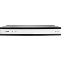

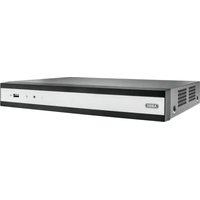
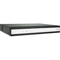

- Français
- Quick guide 105
- Important safety information 106
- Introduction 109
- Status displays. 111
- Setup wizard 112
- Live view 115
- Playback 118
- Main menu 120
- Settings - Configuration 122
- Backup 225
- Handmatig Management 227
- Disque management 291
- Spcifications techniques 304
- Pomouhik Hactpoek 460
- OTo6paKeHne 463
- Bocnpon3BeHne B pexnme OTo6paXeHHN 466
- Mehno npnbopa. 468
- Hac troponi 469
- KoHpyraua 470
- Texnueckoe obcnykubache 492
- ABUS 32-channel Network video recorder NVR TVVR45030
- English
- Device overview
- System operation
- General information
- Operating elements on the device
- i Note
- Connections on the rear of the device
- Remote control (TVAC40930)
- Operating elements on the remote control
- Note
- Mouse operation
- Quick guide. 105
- Status displays 111
- Contents
- Video Export 364
- Panikoptagelse 366
- Bocnpon3BeJeHne B peXnme OTo6paXeHnra 466
- Quick guide
- Before you start
- Installing the HDD
- Warning
- Establishing the connections
- Configuring the device
- Important safety information
- Explanation of symbols
- Symbol
- Signal word Meaning
- Proper use
- Power supply
- Overloading / overvoltage
- Cables
- Installation location / operating environment
- Remote control
- Care and maintenance
- Accessories
- Putting into operation
- Children and the device
- Introduction
- Disclaimer
- Unpacking the device
- Scope of delivery
- On-screen keyboard
- Starting the device
- Important
- Switching off, locking and rebooting the device
- Switching on the device
- Status displays
- Displays on the monitor
- Setup wizard
- Setting up the system
- Setting up the administrator
- Time / Date
- HDD Management
- Setting up network cameras
- Camera recording
- Live view
- Overview
- Status symbols
- Pop-up menu for mouse operation
- Selection bar in the camera image
- Settings
- Setting the camera output
- Playback
- Playback screen
- Using the control panel
- Please klick on ,Tag management' (6):
- Right click when playback is running
- Main menu
- Menu overview
- Settings - Configuration
- General
- Network configuration
- Terms and definitions
- Network layout
- More settings
- Alarm
- Alarm status
- Alarm input
- Handling
- TAB Trigger channel
- TAB Arming schedule
- TAB PTZ Linking
- RS-232
- i
- User
- Permission
- Camera
- PTZ
- Saving and retrieving presets
- Setting up and calling up patrols
- Trigger Channel
- Motion
- Armin Schedule
- Record
- Setting up
- Schedule
- Application example
- Encoding
- TAB Record
- HDD
- HDDs
- HDD settings of the cameras
- Hard disc setting
- Warning:
- Redundancy:
- R/W
- Checking the HDD status
- Setting up the HDD alarm
- S.M.A.R.T.
- Continuous Recording
- i Note Theo
- Event
- Marking
- Image
- Maintenance
- System Info
- Log Search
- Import/Export
- Upgrade
- Default
- Network
- TAB network load
- TAB Network Detection
- Video Export
- Duration
- Event (event type 'Alarm input')
- Event (event type 'Motion')
- Manual Management
- Continuous Capture
- Shutdown
- Troubleshooting
- Device cleaning and care
- Technical data
- HDD storage capacity
- Disposal
- Information on the EU directive on waste electrical and electronic equipment
- Information on handling batteries
- Important information on disposing of batteries
- Information on the European RoHS directive
- Glossary
- Overview of specialist terms
- Dual Stream
- MPEG
- NTP
- NTSC
- PAL
- PANEL
- PC
- Pixel
- PIP
- PPPoE
- PROGRESSIVE
- RESOLUTION
- SCREEN SIZE
- USB
- VGA
- ZOLL (inches)
- Internal HDD
- ABUS Network video recorder NVR
- Baxhblye yka3aHnno TeXnke 6e3onacHocTn 452
- Bvendnne 456
- OtpaxeHne cTaTyca. 459
- Bocnpon3BeJeHne B peKHe OTo6paXeHn 466
- Korte handleiding
- Voordat u begint
- Surcharge/surtension
- Installation at hardisken
- Advarsel
- Henvisning
- HDMI/VGA
- Описиме пибopa
- PepednnaHeJIb
- 3aHnaHeIb
- YnpaBJIeHne cncTeMoN O6uNe NOJoxKeHn
- 3IeMeHbI ynpaBHeHnHa np6ope
- KpaTkaj nHcTpyKzna
- IpepeI npBbIM nCNOJb3OBaHHeM
- Yka3aHne
- YcTaHOBka XeCTKOrO DnCKa
- PpeynpexdHne
- IopknoueHne
- KoHcHpyaun np6opa
- MecTo yCTaHOBKn/YcNoBn3KcnIpyTaun
- #
- BVeDene
- NCKIIOUeHne OTBETCTBEHHOCTn
- 06zaHΦopMaucn
- PacnaKOBka
- ObemIOCTaBKn
- KnaBnataPmaOHToPa
- BkIoueHne np6opa
- BhimaHne!
- BbIKIIOUeHHe, 6IOKIpOBKa, nepe3arpy3Ka np6opa
- BkHoueHne np6opa
- Отразхенистуca
- 06uhe noJoxeHHa
- CBeToIIOIbI COCTOHaHnBnDeOpErNcTpaTopa:
- DMVGA-MOHumOp He noDknOyuH:
- HactpoKa BbIXOa KaMepbI
- KoHpyauncaTn
- CoxpaHeHne N Bbl3OB npeDyctaHOBKn
- YcTaHOBka N Bbl3OB NaTppyJe
- PacnncanHe
- DcCTBnE
- IapametpbI ynpaBHeHЯ JecTKM DnCKOM
- HactpoKn TpeBOrn XecTKoro Dncka
- Bocnpo3BeDeHne
- PpOdoJXHTeJIbHocTb
- 06HOBJIeHHe
- i yka3aHne
- Pon3BecTH BOCCTaHOBJeHne CnCTembl
- PpeynpeKdHne
- Cetb
- Bknadka cTeBaHaHarpy3Ka
- BknaKa PaCno3HaHne cTeN
- BknaKa CtaTnCTnKa ceTeBbIx pecypcoB
- Pe3epB. Konnya
- YcTpaHHeHHeNcPpABHOCTeI
- yTnIIN3aun
- CcbIka Ha dIpuKeTnBy EC no yTuJn3aun cTaporo 3JeKtpnueckoro n 3JeKtpoHnOro o6OpydoBaHna.
- Yka3aHnno o6paueHnIO c 6aTapeaMn
- Baxhna nHΦopMaun!
- Baxnay nHopmaun no ytnnn3aun 6atapei!
- CcbIka Ha dIpuKeTnBy EC RoHS
- Tloccapn
- IcnoJIb3yeMbIe TepMnHbI
- 1080P:
- 16:9
- DnaorohJIb n3o6paKeHHa
- 6pay3ep
- CIF
- CINCH
- DDNS
- DHCP
- Домен
- http
- Upeecctpouha pa3BepTka
- IP-Adpec
- JPEG
- PporpeccnBna pa3BepTka
- RTSP
- SNMP
- OBHHTpeHHem XeCTKOM INCKe
- ABUS CeTeBoI BnDeOpErnCTpaTOp NVR
Brand : ABUS
Model : TVVR45030
Category : VCR