T248 R - Controller THRUSTMASTER - Free user manual and instructions
Find the device manual for free T248 R THRUSTMASTER in PDF.

| Product type | Force feedback racing wheel and T3PM pedal set |
| Brand | Thrustmaster |
| Model | T248 R |
| Weight | 8 kg (wheel and pedals included) |
| Power supply | Power adapter: input 100-240 V, 50/60 Hz; output 18.5 V DC, 2.6 A (47.9 W) |
| Force feedback | DC motor with Boost profiles (FFB1, FFB2, FFB3) and global force adjustment (20% to 100%) |
| Screen | Color LCD screen with backlight (adjustable) and four LEDs (RPM, flag, pit) |
| Gear shift paddles | Magnetic paddles (left/right) |
| Encoders | 4 digital encoders (E1-E4) with E+, E- and EP functions |
| Rotation angle | Adjustable: 180°, 360°, 540°, 900° or automatic (AUTO) |
| Pedal set | 3 pedals (accelerator, brake, clutch) with height, spacing, tilt and brake resistance adjustments |
| Connectivity | USB-C to USB-A, RJ12 port for pedal set, mini-DIN for shifter/handbrake, power port |
| Compatibility | PlayStation 4, PlayStation 5, PC (Windows 10/11) |
| Maintenance | Clean ventilation grilles with a dry cloth or brush. Do not obstruct grilles. |
| Safety | Do not disassemble, use only the provided adapter, keep away from children, avoid any liquids, do not bend cables |
| Operating temperature | 15°C to 30°C |
| Spare parts/repairability | Contact Thrustmaster technical support. No user-serviceable parts. |
| Warranty | Refer to the warranty conditions provided with the product. |
Frequently Asked Questions - T248 R THRUSTMASTER
User questions about T248 R THRUSTMASTER
0 question about this device. Answer the ones you know or ask your own.
Ask a new question about this device
Download the instructions for your Controller in PDF format for free! Find your manual T248 R - THRUSTMASTER and take your electronic device back in hand. On this page are published all the documents necessary for the use of your device. T248 R by THRUSTMASTER.
USER MANUAL T248 R THRUSTMASTER
Carefully read the instructions provided in this manual before installing the product, before any use of the product and before any maintenance. Be sure to follow the safety instructions. Failure to follow these instructions may result in accidents and/or damage. Keep this manual so that you can refer to the instructions in the future.
TABLE OF CONTENTS
- BOX CONTENTS......7
- FEATURES 8
- INFORMATION REGARDING USE OF THE RACING WHEEL....13
- INFORMATION REGARDING USE OF THE PEDAL SET ......21
- INSTALLING THE RACING WHEEL ON A TABLE OR DESK......25
- INSTALLING THE RACING WHEEL AND PEDAL SET ON A SUPPORT* OR IN A COCKPIT*......27
- INSTALLATION 29
On PlayStation®4 consoles 29
On PlayStation®5 consoles 33
On PC* 37
Automatic calibration of the racing wheel and pedals....44
8. MAPPING FOR PLAYSTATION®4
CONSOLES OR PLAYSTATION®5
CONSOLES 46
Using the encoders....47
9. MAPPING FOR PC 49
Using the encoders....50
10. COMPATIBLE GAMES ....52
Changing the compatibility mode ....54
Accessing the Settings or Telemetry
submenu....58
Settings submenu 60
Telemetry submenu 75
Flag (FLAG) and pit (PIT)*......87
Engine speed (RPM)* 87
13. ADJUSTING THE PEDAL SET .....90
Adjusting the height of the accelerator
pedal 91
Adjusting the spacing of the pedals .....93
Adjusting the inclination of the pedals....95
Modifying the brake pedal's resistance...97
14. FAQ AND TECHNICAL SUPPORT......102
T248R
With its interactive color dashboard and powerful, realistic and versatile Force Feedback, T248R is an accessory designed for racing drivers seeking performance and immersion.
This manual will help you install and use your T248R under the best conditions. Before getting started racing, carefully read the instructions and the warnings: they will help you get the most enjoyment out of your product.

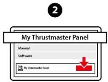
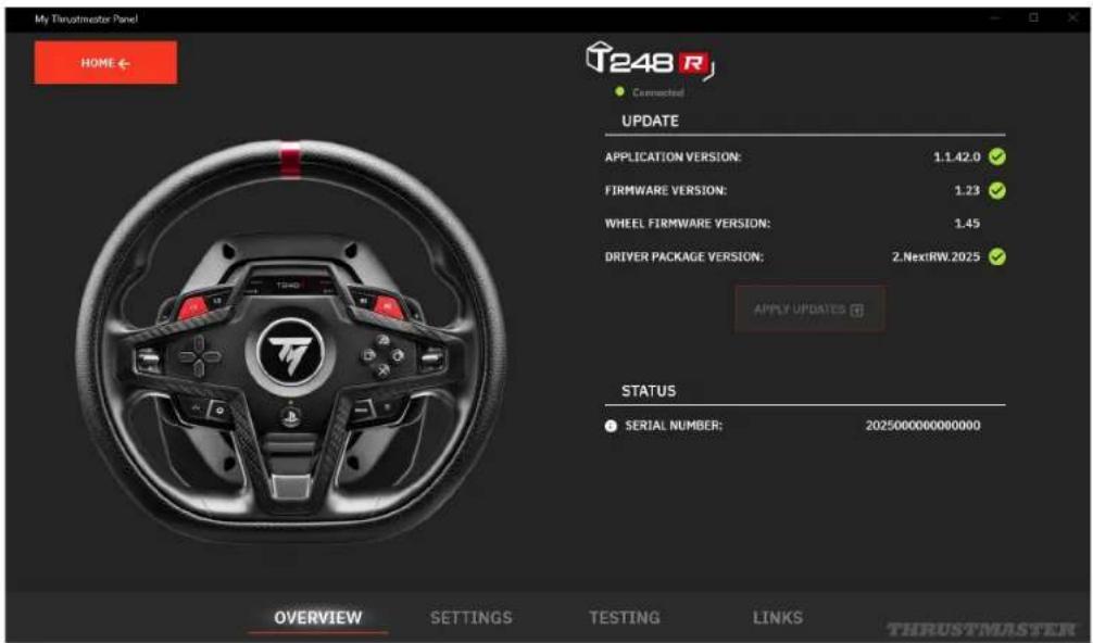
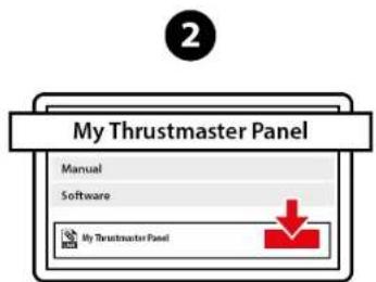
Updating the firmware
In order for the T248R racing wheel to work properly with video games, you must update its firmware.
To carry out the update:
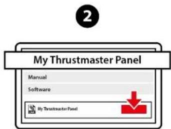
- Go to
https://support.thrustmaster.com/product/T248r/
- Download and install the My Thrustmaster Panel software available in the Software section and follow the instructions.

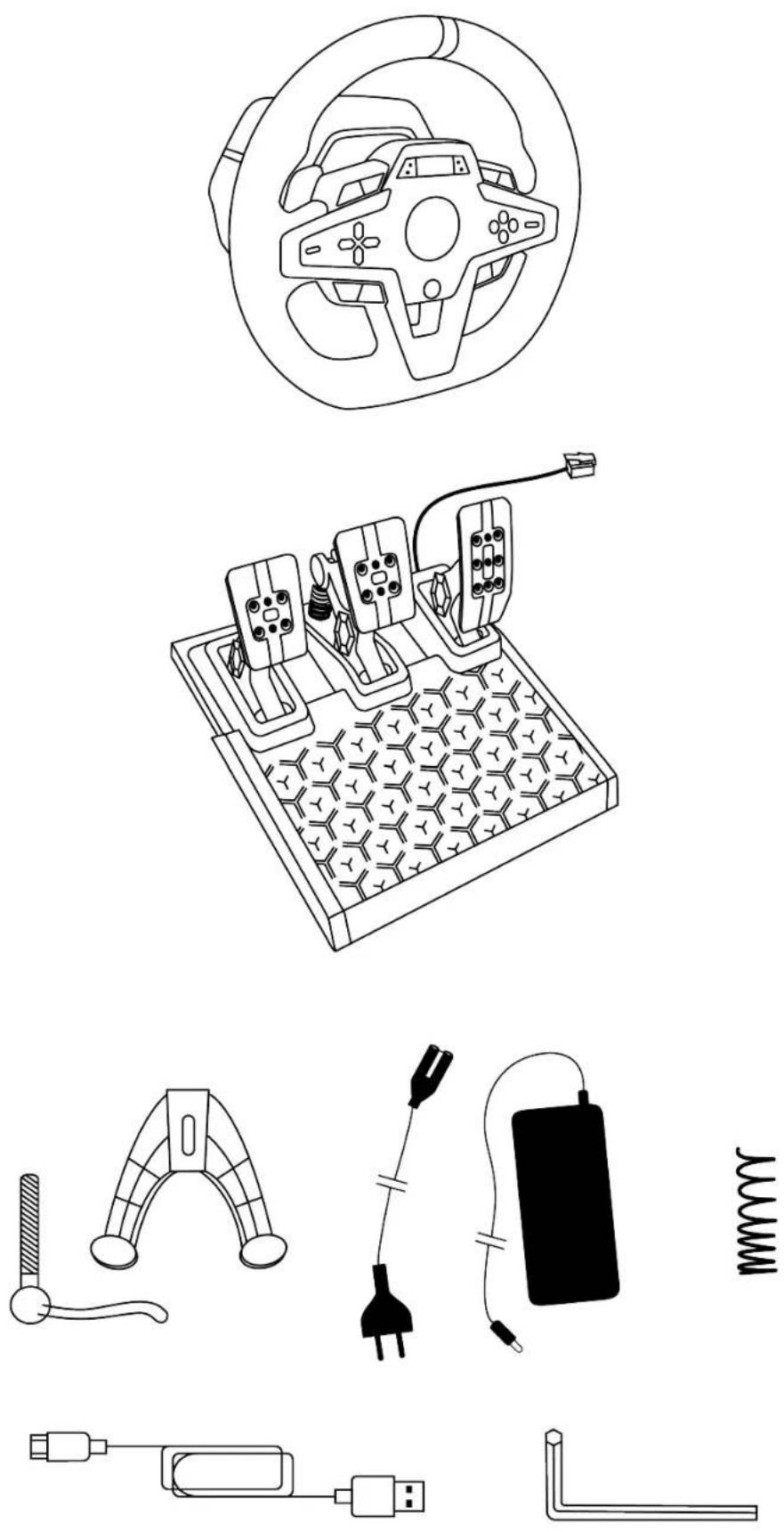
1. Box contents
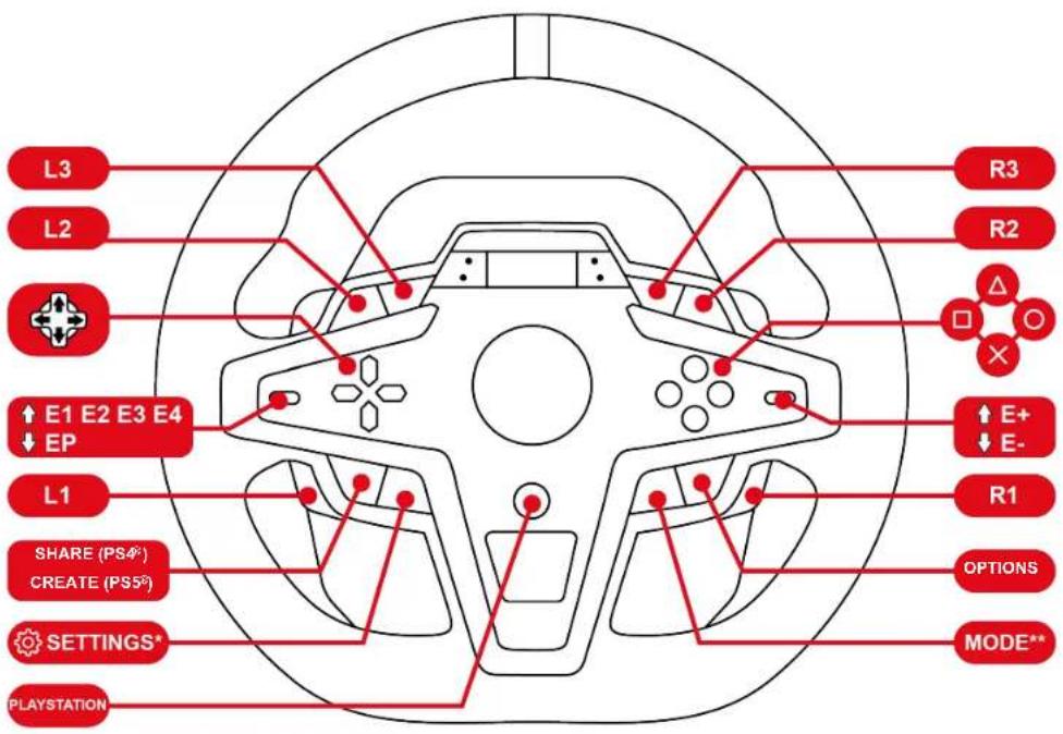
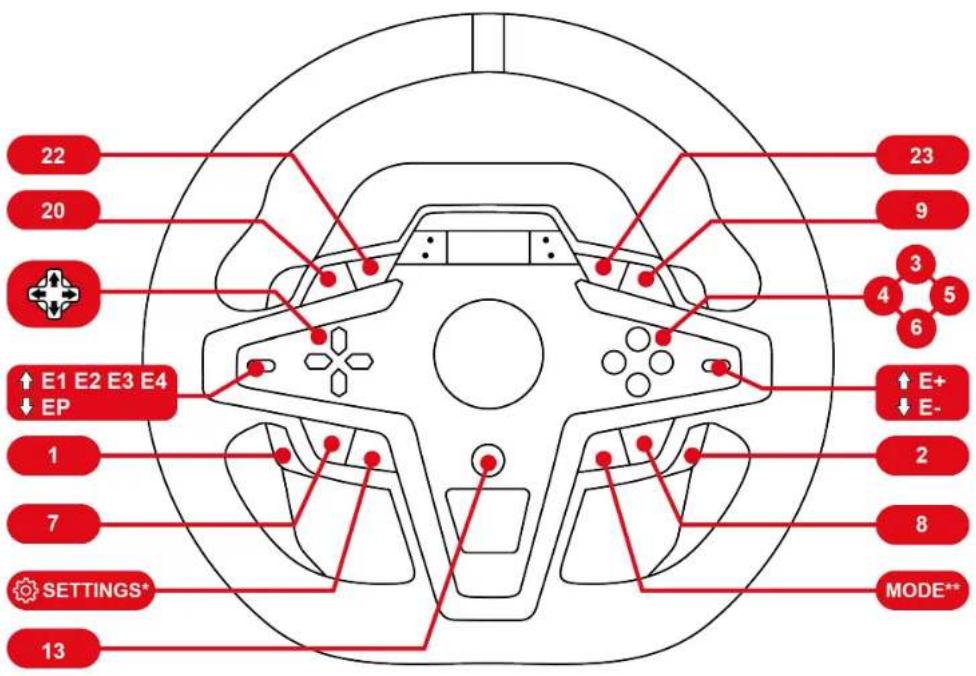
2. Features
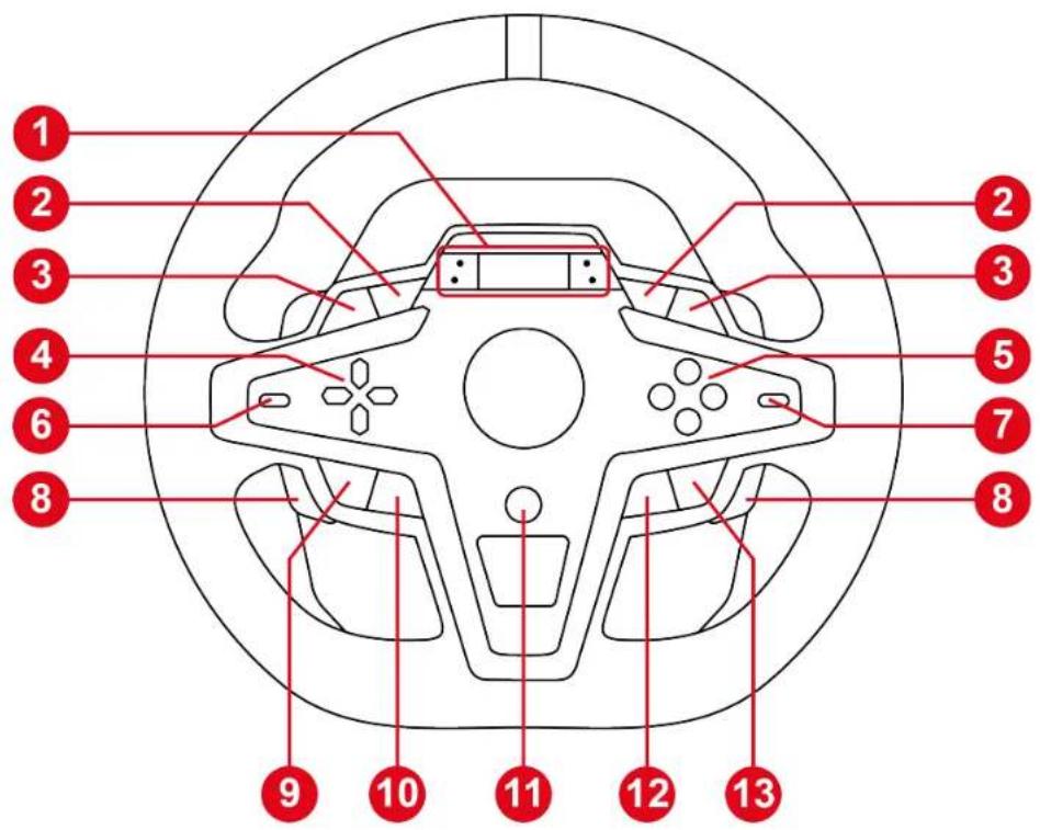
① Color LCD screen and four LEDs (race information: RPM, flag, pit)
② L3 and R3 buttons
③ L2 and R2 buttons
4 Directional buttons
5 Action buttons
6 Encoder selector and EP function
⑦ E+ and E- functions
8 Magnetic paddle shifters
9 SHARE button on PS4® consoles / CREATE button on PS5® consoles
10 button (Settings)
11 PS button
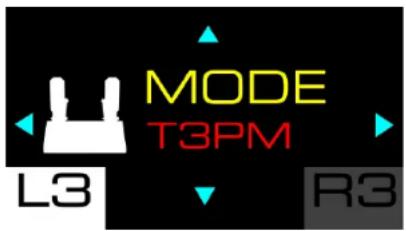
12 MODE button
13 OPTIONS button on PS4 ^® consoles and PS5 ^® consoles

14 Large screw thread for attachment system
15 Power port
16 USB-C port
17 Mini-DIN connector for Thrustmaster shifter, handbrake or hub (sold separately)
18 RJ12 port for pedal set
19 Screw threads for installation in a cockpit (not included)
20 Hook-and-loop fastener cable holder
21 Spring retaining rod
22 Upper retaining head with washer
23 Elastomer cushioning ring (white – Shore 70)
24 Upper plastic spacer (red)
25 Soft spring (silver – installed by default)
26 Lower plastic spacer (red)
27 Additional hard spring (black)
28 Pedal set's RJ12 connector
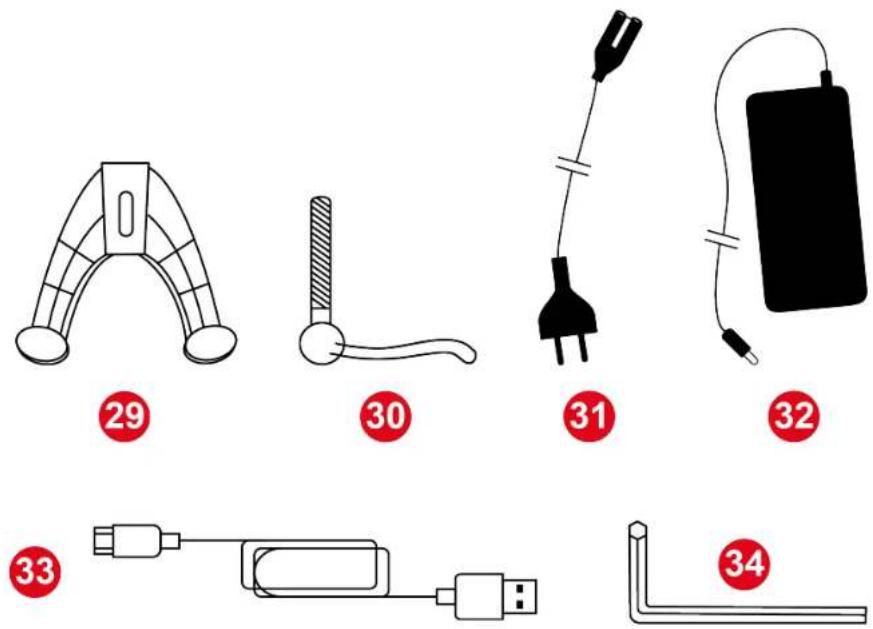
29 Attachment system
30 Fastening screw
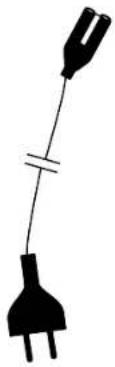
31 Power cable (EU/US or UK...)
32 Power adapter
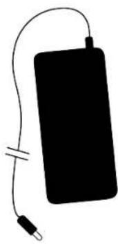
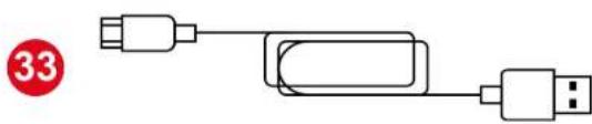
33 USB-C – USB-A cable
34 2.5 mm Allen key
3. Information regarding use of the racing wheel

Documentation
Before using this product, carefully read this documentation again and keep it for future reference.

Electrical shock
- Keep the product in a dry location and do not expose it to dust or sunlight.
- Use the product in an environment with a temperature between 15^ and 30^ .
- Do not twist or pull on the connectors and cables.
- Follow the connection directions.
- Do not spill any liquid on the product or its connectors.
- Do not short-circuit the product.
- Never dismantle the product; do not throw it onto a fire and do not expose it to high temperatures.
- Do not use a power supply cable other than the one provided with your racing wheel.
- Do not use the power supply cable if the cable or its connectors are damaged, split or broken.
- Make sure that the power supply cable is properly plugged into an electrical outlet, and properly connected to the connector at the rear of the racing wheel's base.
-
Do not open up the racing wheel: there are no user-serviceable parts inside. Any repairs must be carried out by the manufacturer, its authorized representative or a qualified technician.
-
If the racing wheel is operating abnormally (if it is emitting any abnormal sounds, heat or odors), stop using it immediately, unplug the power supply cable from the electrical outlet and disconnect the other cables.
- If you will not be using the racing wheel for an extended period of time, unplug its power supply cable from the wall outlet.
- The wall outlet must have been installed according to proper electrical trade practices by a specialist.
- The wall outlet must be located near the equipment and must be easily accessible.
- The use of an extension cord or cords is not recommended, due to the risk of the extension cord overheating and therefore the risk of fire.
- Do not plug the device into a wall outlet or unplug it with damp or wet hands.
- Never carry the power supply by holding the cable.
- Never unplug or disconnect the power supply by pulling on the cable.

Power supply
- Use only the power supply listed in the user instructions.
- Only use the power supply with the electrical network voltage and frequency indicated on the power supply's rating plate.

Securing the gaming area
- Do not place any object in the gaming area which may disrupt the practice of the user, or which may provoke an inappropriate movement or an interruption by another person (coffee cup, telephone, keys, for example).
- Do not cover the power cables with a carpet or rug, blanket or covering or any other item, and do not place any cables where people will be walking.

Information for power supply adapter
| Information published | Value Unit | |
| Manufacturer's name or trademark Business number Address | GUILLEMOT CORPORATION S.A. 414 196 758 R.C.S. Vannes 2 Rue du Chêne Héleuc 56910 Carentoir France | |
| Model identifier | A481-1852590D | |
| Input voltage | 100 – 240 | V |
| Input AC frequency | 50 – 60 Hz | |
| Output voltage | 18.5 | V DC |
| Output current | 2.6 | A |
| Output power | 47.9 | W |
| Average active efficiency | 87.8 % | |
| Efficiency at low load (10%) | 87.8 % | |
| No-load power consumption | 0.10 W |

Air vents
Make sure not to block any of the air vents on the racing wheel's base. For optimal ventilation, make sure to do the following:
- Position the wheel's base at least 4 inches/10 cm away from any wall surfaces.
- Do not place the base in any tight spaces.
- Do not cover the base.
- Do not let any dust build up on the air vents. Clean them regularly with a dry cloth or a brush and do not obstruct the sides or top of the base.
- Never insert any object or body part into the product's air vents.

During intensive use, you may notice a slight odor emanating from the base. This specific case mainly occurs with new products: it is normal, and subsides over time.

Injuries due to Force Feedback and repeated movements
Playing with a Force Feedback racing wheel may cause muscle or joint pain. To avoid any problems:
- Avoid overly-long gaming periods (more than 2 hours).
- Take a 10 to 15-minute break after each hour of play.
- If you feel any fatigue or pain in your hands, wrists, arms, feet or legs, stop playing and rest for a few hours before you start playing again.
- If the symptoms or pain indicated above persist when you start playing again, stop playing and consult your doctor.
- Keep out of children's reach.
- Make sure that the racing wheel's base is properly secured, as per this manual's instructions.
natural_image
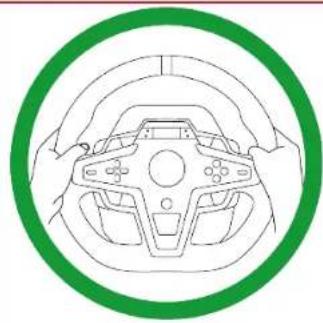
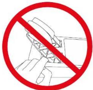
Top-down line drawing of a car steering wheel with hands operating it, enclosed in a green circular border (no text or symbols)Risk of unforeseen, powerful and rapid rotations: never place a hand or an arm through the openings in the wheel rim, or in the wheel's trajectory of rotation.
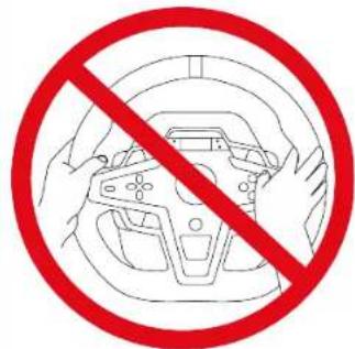
When using the product, always leave both hands correctly positioned on the wheel without ever completely letting go.

Product to be handled only by people 14 years of age or older.

Heavy product – Be careful not to drop the product on yourself or on anyone else.
4. Information regarding use of the pedal set

Documentation
Before using this product, carefully read this documentation again and keep it for future reference.

For safety reasons, never use the pedal set with bare feet or while wearing only socks on your feet. Thrustmaster® disclaims all responsibility in the event of injury resulting from use of the pedal set without shoes.

Electrical shock
- Keep the product in a dry location and do not expose it to dust or sunlight.
- Do not twist or pull on the connectors and cables.
- Follow the connection directions.
- Do not spill any liquid on the product or its connectors.
- Do not short-circuit the product.
- Never dismantle the product (except in the cases of customization specified in this manual); do not throw it onto a fire and do not expose it to high temperatures.

Injuries due to repeated movements
Playing with a pedal set may cause muscle or joint pain.
To avoid any problems:
- Avoid overly-long gaming periods (more than 2 hours).
- Take a 10 to 15-minute break after each hour of play.
- If you feel any fatigue or pain in your feet or legs, stop playing and rest for a few hours before you start playing again.
- If the symptoms or pain indicated above persist when you start playing again, stop playing and consult your doctor.

Pedal set pinch hazard when playing
- Keep the pedal set out of children's reach.
- During gameplay, never place your fingers (or other body parts) on or near the sides, rear base or front base of the pedals.
5. Installing the racing wheel on a table or desk

- Only use the attachment system included with the racing wheel.
- Never tighten the fastening screw alone without the attachment system in place. This could damage the racing wheel.
- Before each use, verify that the base is still properly attached to the support, as per this manual's instructions.

Make sure that you have connected all of the cables before installing the racing wheel on a table or desk. For more information, please refer to the section dedicated to installation on PlayStation®4 consoles, PlayStation®5 consoles or PC.
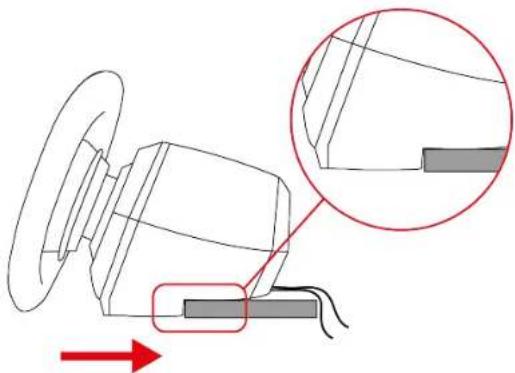
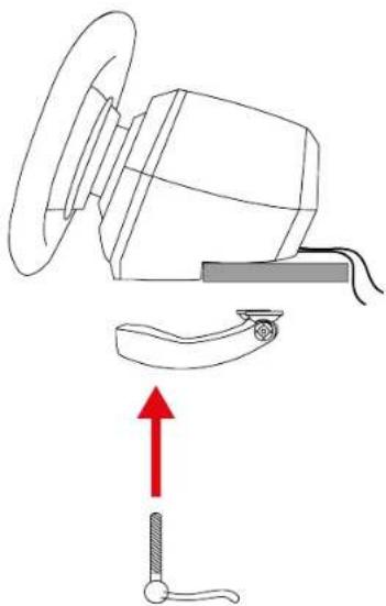
- Place the racing wheel on a table or desk.
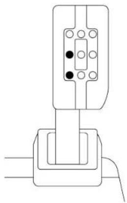
natural_image
Technical diagram of a mechanical assembly with a magnified inset showing a detail (no text or symbols)- Insert the fastening screw into the attachment system.
natural_image
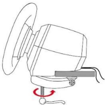
Diagram of a mechanical device with a red upward arrow indicating motion or force (no text or symbols present)- Screw the assembly into the large screw thread located under the racing wheel, until the racing wheel is perfectly stable.
natural_image
Technical line drawing of a mechanical device with a rotating knob and rotating arm (no text or symbols)6. Installing the racing wheel and pedal set on a support\* or in a cockpit\*

The installation template for T248R and the pedal set on supports is available here:
https://support.thrustmaster.com/product/t248r (in the Manual section).

The length of the two M6 screws must not exceed the thickness of the shelf by more than 0.47 inches/12 mm; longer screws could cause damage to internal components located in the racing wheel's base.
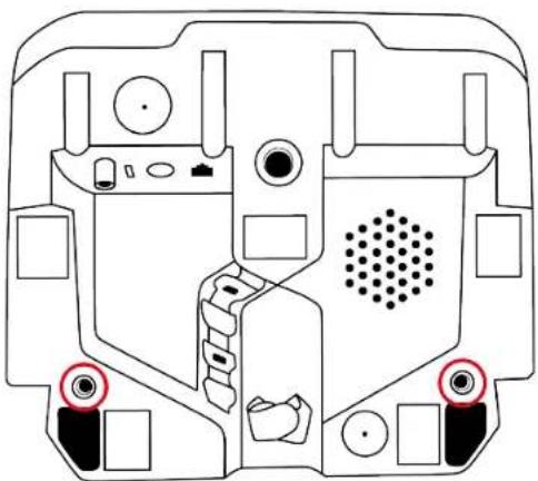
Attaching the racing wheel:
Use the two screw threads located under the racing wheel and two M6 screws (not included).
natural_image
Technical line drawing of a mechanical component with no visible text or symbols
If necessary, you can also screw the included attachment system into the large screw thread.
Attaching the pedal set:
Use the screw threads located under the pedal set and at least two M6 screws (not included).
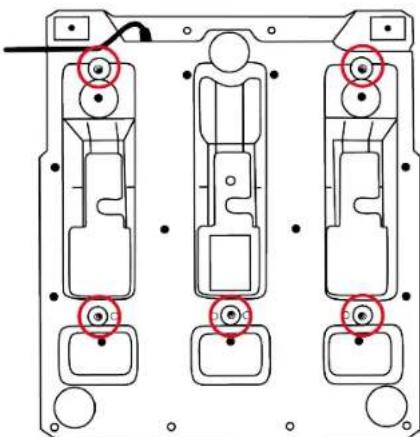
natural_image
Technical diagram of three mechanical components with red circular annotations indicating features (no text or symbols present)7. Installation
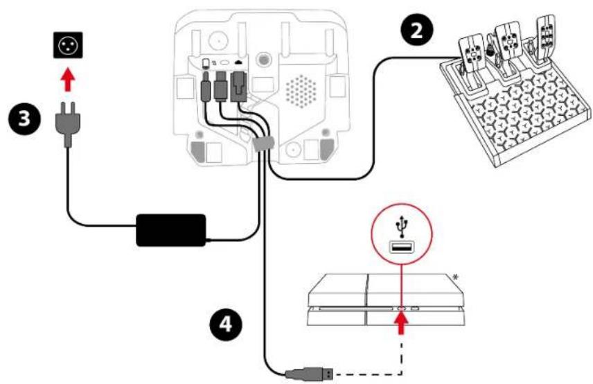
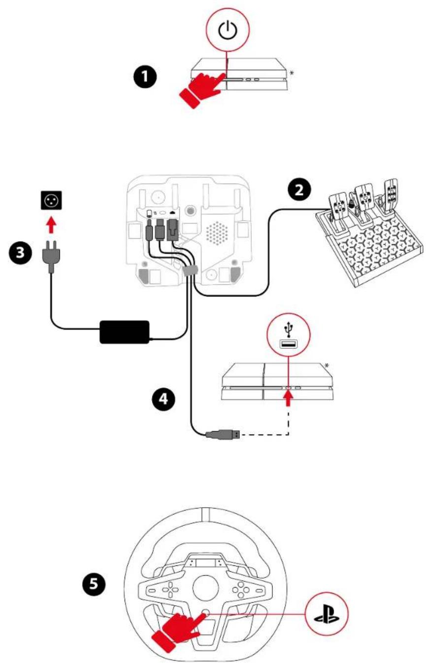
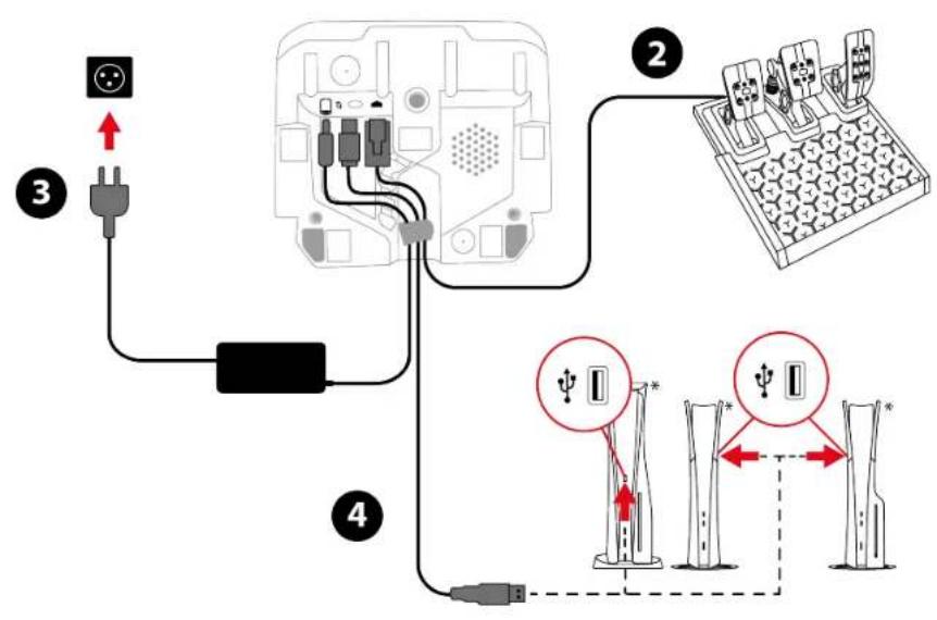
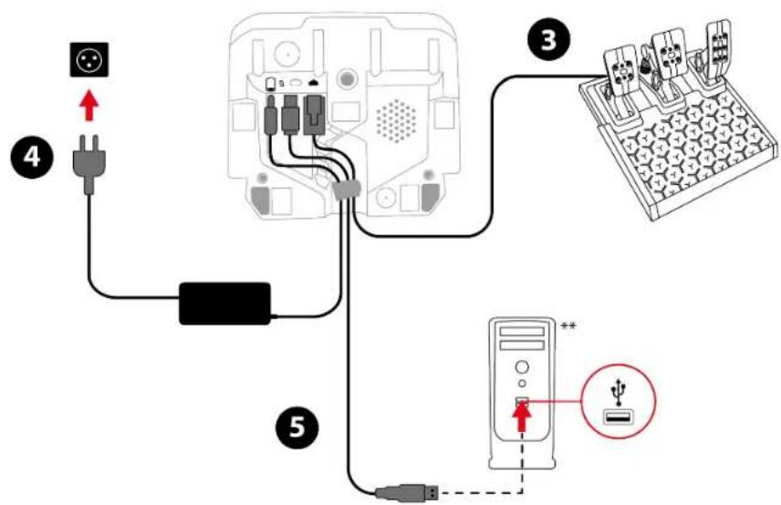
On PlayStation®4 consoles
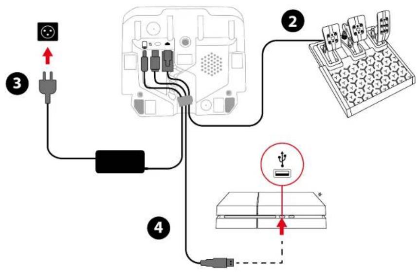

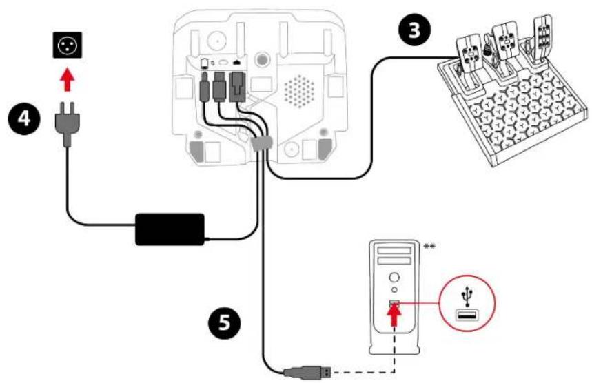
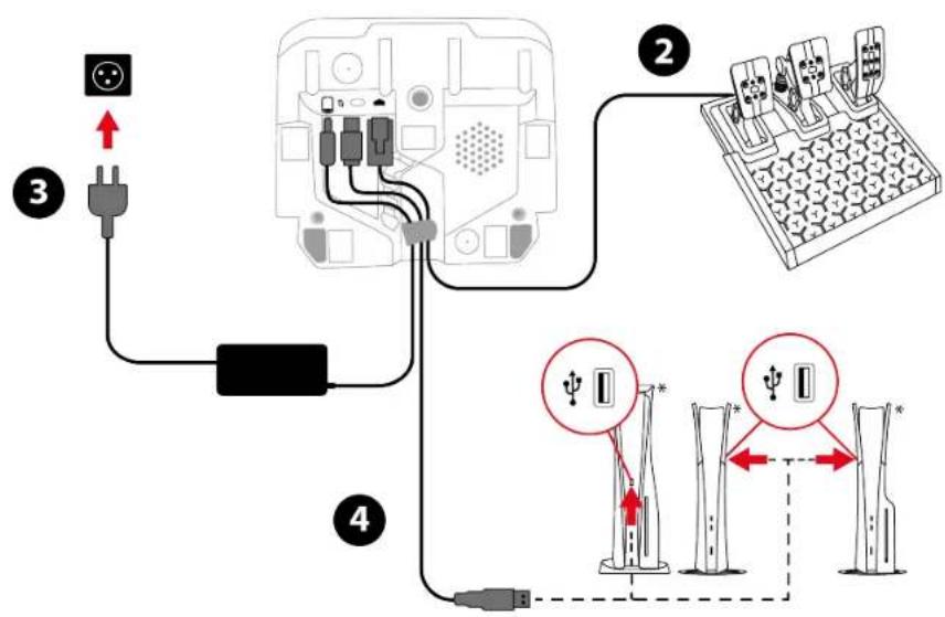
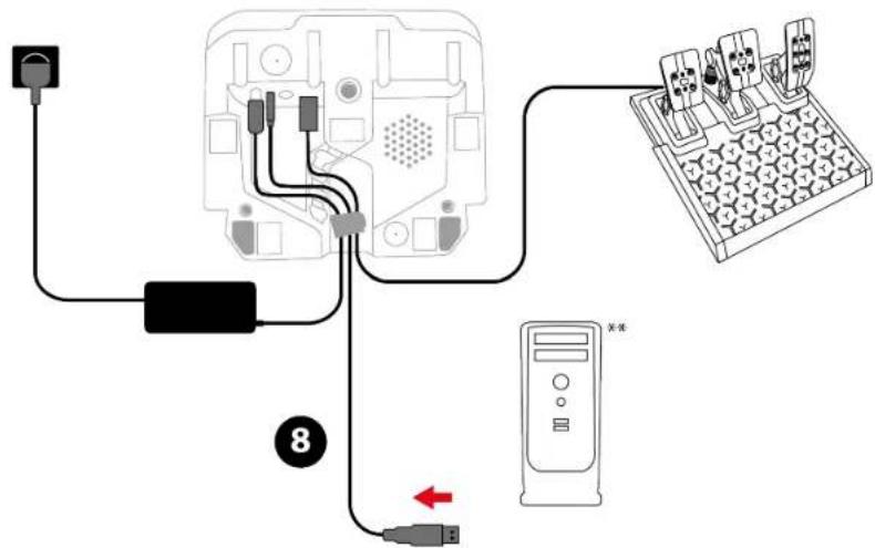
Run the cables through the designated channels on the underside of the racing wheel, and secure the cables using the cable holder.
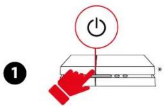
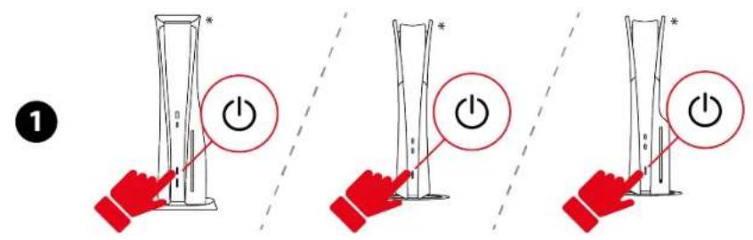
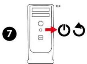
- Power on your PlayStation®4 console.
- Connect the pedal set to the RJ12 port on the racing wheel.
- Connect the power adapter to the racing wheel, and plug it into an electrical outlet.
-
Connect the USB-C – USB-A cable to the racing wheel's USB-C port, and to a USB-A port on the PlayStation®4 console.
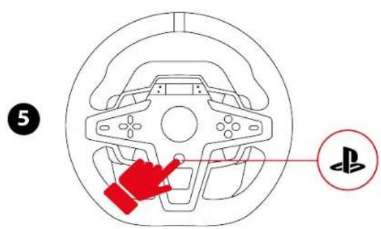
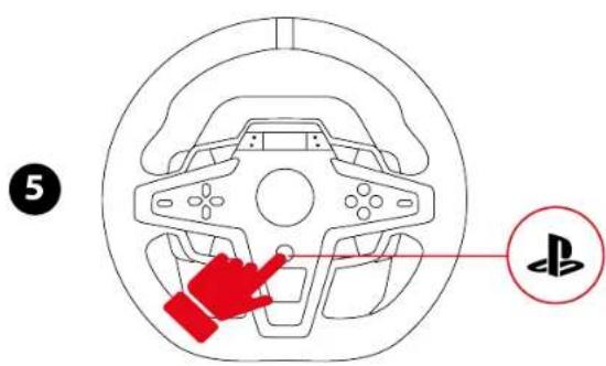
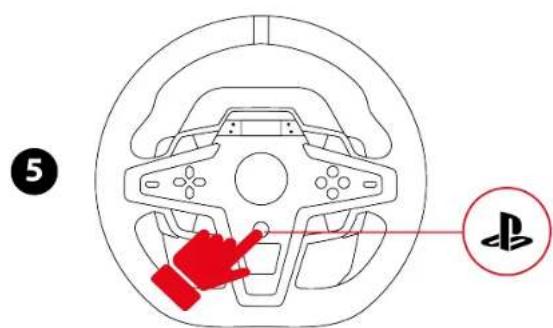
Your racing wheel calibrates itself automatically. -
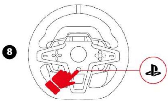
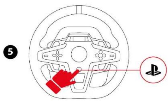
Press the ⏻ button to connect the racing wheel to your profile.
-
The racing wheel's screen lights up. The LED should be blue.
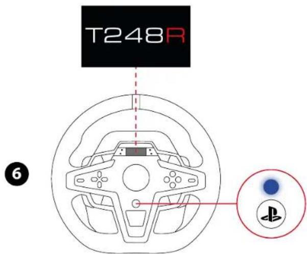
-
If the LED is not blue, change the compatibility mode by following the procedure set out here.
-
Press the ⏻ button to connect the racing wheel to your profile.

During the racing wheel's self-calibration phase, make sure not to put your hands on the wheel rim.

You are now ready to play!
On PlayStation®5 consoles


*Not included

Run the cables through the designated channels on the underside of the racing wheel, and secure the cables using the cable holder.
- Power on your PlayStation®5 console.
- Connect the pedal set to the RJ12 port on the racing wheel.
- Connect the power adapter to the racing wheel, and plug it into an electrical outlet.
- Connect the USB-C – USB-A cable to the racing wheel's USB-C port, and to a USB-A port on the PlayStation®5 console.
Your racing wheel calibrates itself automatically. -
Press the ⏻ button to connect the racing wheel to your profile.
-
The racing wheel's screen lights up. The LED should be blue.

-
If the LED is not blue, change the compatibility mode by following the procedure set out here.
-
Press the ⏻ button to connect the racing wheel to your profile.


During the racing wheel's self-calibration phase, make sure not to put your hands on the wheel rim.

You are now ready to play!
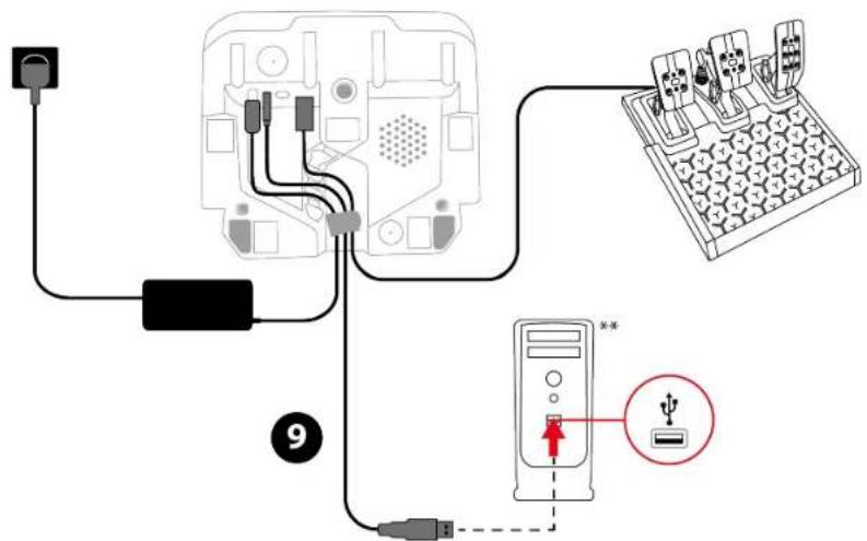
On PC\*


*PC compatibility (Windows® 10/11) not tested or endorsed by Sony Interactive Entertainment.
**Not included

Run the cables through the designated channels on the underside of the racing wheel, and secure the cables using the cable holder.
- Go to:
https://support.thrustmaster.com/product/t248r
-
Download and install the My Thrustmaster Panel software, available in the Software section.
-
Connect the pedal set to the RJ12 port on the racing wheel.
-
Connect the power adapter to the racing wheel, and plug it into an electrical outlet.
-
Connect the USB-C – USB-A cable to the racing wheel's USB-C port, and to a USB-A port on the PC. Your racing wheel calibrates itself automatically.
-
In the My Thrustmaster Panel software, your racing wheel is automatically detected. Click INSTALL DRIVER and follow the instructions to install the PC driver (X_NextRW_202x).
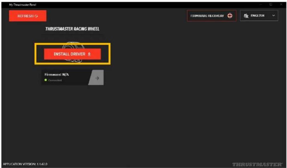
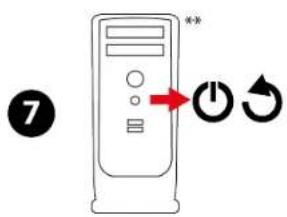
- Once the driver has been installed, restart the PC.
- Disconnect the USB-C - USB-A cable from the PC.

- Once your PC has restarted, reconnect the USB-C – USB-A cable to a USB-A port on the PC.
- The racing wheel automatically switches to PC mode and the screen lights up. The LED should be green.
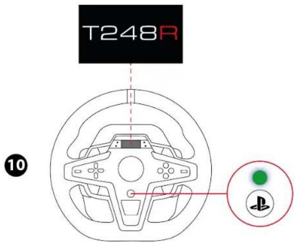
- If the LED is not green, change the compatibility mode by following the procedure set out here.

During the racing wheel's self-calibration phase, make sure not to put your hands on the wheel rim.
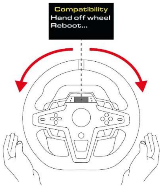
You are now ready to play!
My Thrustmaster Panel software

The My Thrustmaster Panel software lets you access all of the racing wheel's features (testing the buttons, adjusting the Force Feedback and the rotation angle, etc.).
Automatic calibration of the racing wheel and pedals
The wheel rim automatically self-calibrates when you plug the racing wheel into an electrical outlet and connect the racing wheel's USB connector to the PlayStation®4 / PlayStation®5 console or PC.
During this phase, the racing wheel will rotate quickly towards the left and the right, covering a 900-degree angle, before stopping at the center.

Never touch the racing wheel during the self-calibration phases. This could result in improper calibration and/or personal injuries.

Never disconnect the pedal set from the racing wheel or connect it to the racing wheel when the PlayStation®4 console, PlayStation®5 console or PC is powered on. This could result in improper calibration.

Always connect the pedal set before connecting the racing wheel to the PlayStation®4 console, PlayStation®5 console or PC.
Once the racing wheel's calibration is complete and the game has been started, the pedals are automatically calibrated after a few presses.

Never press the pedals when powering on your console or your PC, starting a game or changing the compatibility mode, or during the racing wheel's self-calibration phases. This could result in improper calibration.

If your racing wheel and/or pedal set do not function correctly, or if they seem to be improperly calibrated: power off your console or PC and completely disconnect the racing wheel. Then reconnect all cables (including the power supply cable and the pedal set), and restart your console or PC and your game.
8. Mapping for PlayStation®4 consoles or PlayStation®5 consoles

On PlayStation®4 consoles or PlayStation®5 consoles, the racing wheel is recognized with the following name in games: Thrustmaster T-GT or Thrustmaster Advanced Racer.
*SETTINGS: please refer to the Accessing the Settings or Telemetry submenu section.
**MODE: please refer to the Changing the compatibility mode section.
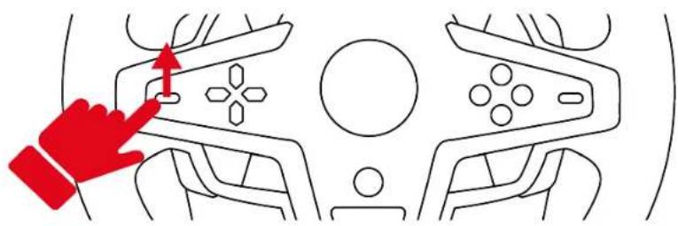
Using the encoders
To choose the active encoder, push the encoder selector upwards.

natural_image
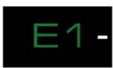
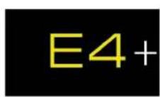
Diagram showing a hand pointing to a device component with no visible text or symbolsThe active encoder is displayed on the screen: E1, E2, E3 and E4, in succession.
Combine the active encoder with the E+, E- or EP function to access the action of your choice.
| E1 | E2 | E3 | E4 | |
| EP | E1P | E2P | E3P | E4P |
| E+ | E1+ | E2+ | E3+ | E4+ |
| E- | E1- E2- E3- E4- | |||
The corresponding action is displayed on the screen.


- Encoders E1, E2, E3 and E4 work in games compatible with Thrustmaster encoders. The list of compatible games is available here: https://support.thrustmaster.com/product/T248r/ (in the Games settings section). This list is updated regularly.
- The screen displaying telemetry information functions in games compatible with the Thrustmaster SDK. The list of compatible games is available here: https://support.thrustmaster.com/product/T248r/ (in the Games settings section). This list is updated regularly.
9. Mapping for PC

On PC, the racing wheel is recognized with the following name in games: Thrustmaster Advanced Mode Racer.
*SETTINGS: please refer to the Accessing the Settings or Telemetry submenu section.
**MODE: please refer to the Changing the compatibility mode section.
Using the encoders
To choose the active encoder, push the encoder selector upwards.
natural_image
Diagram showing a hand pointing to a device component with no visible text or symbolsThe active encoder is displayed on the screen: E1, E2, E3 and E4, in succession.
Combine the active encoder with the E+, E- or EP function to access the action of your choice.
| E1 | E2 | E3 | E4 | |
| EP | 11 | 12 | 24 | 25 |
| E+ | 14 | 17 | 19 | 21 |
| E- | 15 | 16 | 18 | 20 |
The corresponding action is displayed on the screen.


- Encoders E1, E2, E3 and E4 work in games compatible with Thrustmaster encoders. The list of compatible games is available here: https://support.thrustmaster.com/product/T248r/ (in the Games settings section). This list is updated regularly.
- The screen displaying telemetry information functions in games compatible with the Thrustmaster SDK. The list of compatible games is available here: https://support.thrustmaster.com/product/T248r/ (in the Games settings section). This list is updated regularly.
10. Compatible games
The list of compatible games for PlayStation®4 consoles and PlayStation®5 consoles is available here:
https://support.thrustmaster.com/product/T248r/
In the Games settings section, select PlayStation® Games list. This list is updated regularly.
11. Screen operation
The racing wheel's screen lets you:
- Change the compatibility mode;
- Access the Settings or Telemetry submenus;
- Change the settings for the racing wheel and pedal set, and the brightness of the screen and LEDs;
- Select the telemetry information to be displayed.
Changing the compatibility mode
The racing wheel has three compatibility modes:
- On PlayStation ^® 4 consoles and PlayStation ^® 5 consoles, select PLAYSTATION MODE 1 (blue LED).
- On PC, select PC MODE (green LED).
- The red LED corresponds to an inactive mode. It will be available in the future.
| LED color | Mode |
 | PLAYSTATION MODE 1Standard compatibility(default mode) |
 | Future compatibility(inactive mode) |
 | PC MODE |

Do not select the red LED.
To change the compatibility mode:
- Press the MODE button.
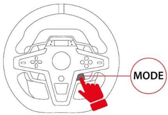
- Use the directional buttons ✕ to display the compatibility mode of your choice.
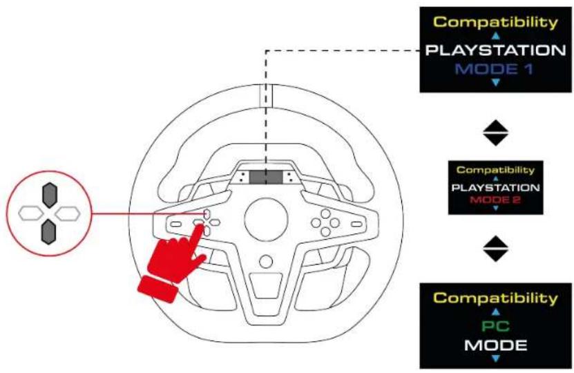
flowchart
graph TD
    A["PC MODE"] --> B["Playstation MODE 1"]
    B --> C["Playstation MODE 2"]
    C --> D["Compatibility PC MODE"]
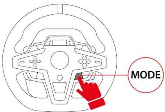
- Press the MODE button to confirm the selection. Your selection is saved in the racing wheel's internal memory.
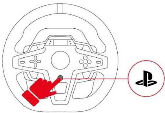
- On PlayStation ^® 4 consoles and PlayStation ^® 5 consoles, press the button to connect the racing wheel to your profile.

- If the selected mode is identical to the mode that was previously selected, the screen you were on before selecting the mode is displayed.
- If the selected mode is different from the mode that was previously selected, the racing wheel will restart and perform a self-calibration.

During the racing wheel's self-calibration phase, make sure not to put your hands on the wheel rim.
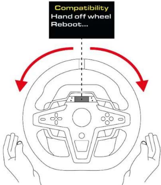
You are now ready to play!
Accessing the Settings or Telemetry submenu

For safety reasons and to avoid any risk of injury, we very strongly advise you to pause the game before pressing the ⏻ button (Settings).

When you are in the Settings or Telemetry submenu, the directional buttons are disabled in games and in the console's interface.
To display the Settings or Telemetry submenu selection screen:
- Press the ⏻ button (Settings).
The following screen is displayed:
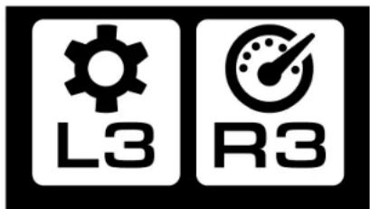
- Press the L3 button to select the Settings submenu.
The following screen is displayed:
Press the R3 button to select the Telemetry submenu.
The following screen is displayed:
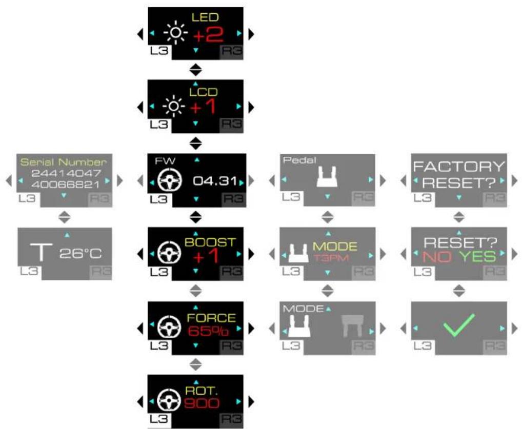
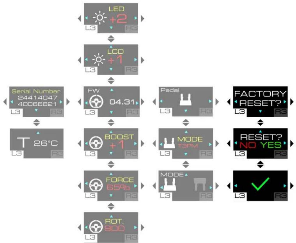
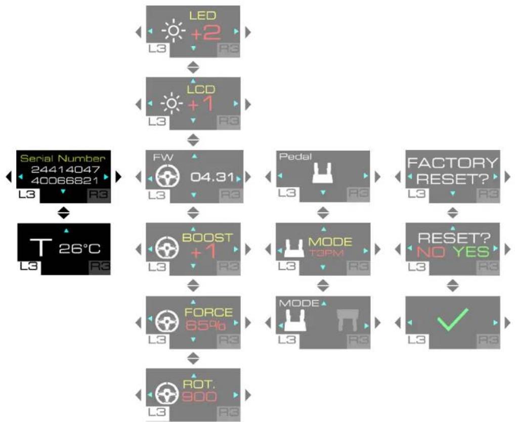
Settings submenu
The Settings submenu lets you display information about the racing wheel and pedal set, and change their settings.

To access the Settings submenu, press the ⏻ button (Settings), then press the L3 button.
The following screen is displayed:
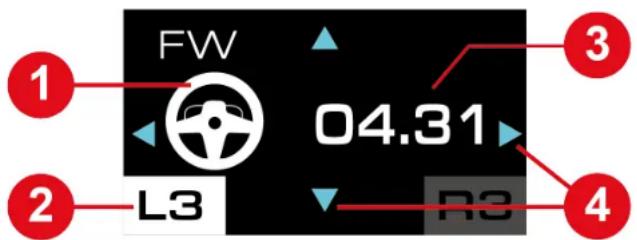
① Accessory involved: wheel rim or pedal set
② Selected Settings submenu
③ Information about the racing wheel or the pedal set or settings to be changed
4 Possible navigation in the submenu
To navigate through the Settings submenu:
- Use the directional buttons.
To change the value of a setting:
- Use the directional buttons.
To confirm the value of a setting:
- Press the ⏻ button (Settings).
You will exit the Settings submenu and the screen will display the telemetry information (SPEED + GEAR screen by default).
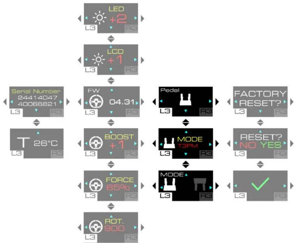
Racing wheel settings
flowchart
graph TD
    A["LED +2 L3"] --> B["LCD +1 L3"]
    B --> C["FW 04.31 L3"]
    C --> D["BOOST +1 L3"]
    D --> E["FORCE 65% L3"]
    E --> F["ROT 900 L3"]
    G["Serial Number 24414047 400666821 L3"] --> C
    H["T 26°C L3"] --> D
    I["Pedal L3"] --> D
    J["FACTORY RESET? L3"] --> D
    K["RESET? NO YES L3"] --> E
    L["MODE T3PM L3"] --> E
    M["MODE L3"] --> E
    N["✓ L3"] --> F
Adjusting the LEDs' brightness
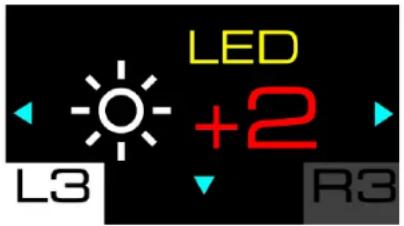
This screen lets you change the brightness of the LEDs. Five settings are possible: -2; -1; 0 (default setting); +1; +2.
Adjusting the screen's brightness
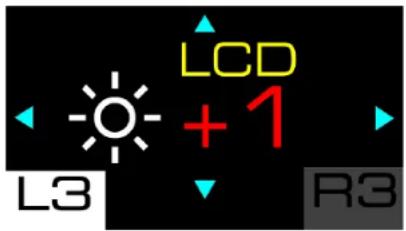
This screen lets you change the overall brightness of the screen's display. Three settings are possible: -1; 0 (default setting); +1.
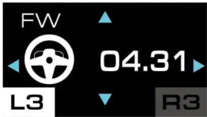
Racing wheel firmware
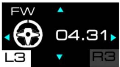
This screen shows the firmware version of the racing wheel.
Boost (Force Feedback profiles)
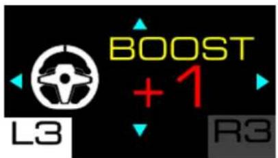
This screen is used to select the Force Feedback profile. You have the choice between three saved profiles, ranging from the least aggressive Force Feedback to the most aggressive: 0 (FFB 1); +1 (FFB 2 – default); +2 (FFB 3).
line
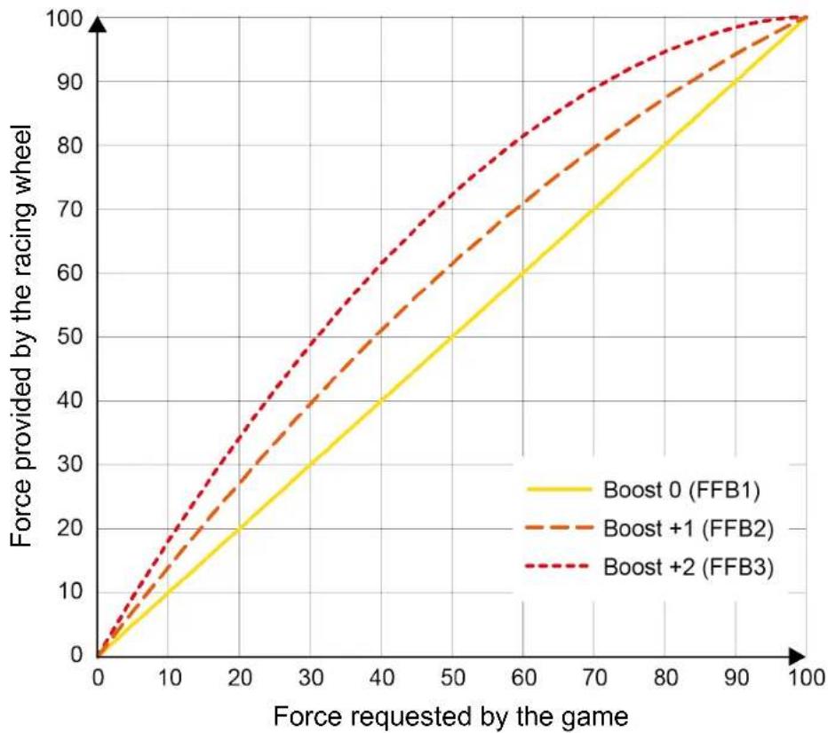
| Force requested by the game | Boost 0 (FFB1) | Boost +1 (FFB2) | Boost +2 (FFB3) | | --------------------------- | -------------- | --------------- | --------------- | | 0 | 0 | 0 | 0 | | 20 | 20 | 30 | 40 | | 40 | 40 | 50 | 60 | | 60 | 60 | 70 | 80 | | 80 | 80 | 90 | 95 | | 100 | 100 | 100 | 100 |Boost 0 (FFB 1)
The Boost 0 (FFB 1) effect provides linear Force Feedback. The force that you feel is 100 % proportional to the force requested by the game.
Boost + 1 (FFB 2) and Boost + 2 (FFB 3)
The Boost + 1 (FFB 2) and Boost + 2 (FFB 3) effects boost the Force Feedback in order to accentuate the force that you feel in relation to the force requested by the game.
Force (overall Force Feedback)
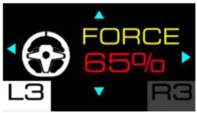
This screen lets you adjust the overall power of the Force Feedback effects. There are six settings to choose from: 20%; 35%; 50%; 65% (default); 80%; 100%.
Rotation angle
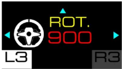
This screen lets you set the racing wheel's angle of rotation. There are five settings to choose from: 180°; 360°; 540°; 900°; AUTO (default).

- When the wheel rim's angle of rotation is set to AUTO, the angle is automatically adjusted by the game according to the vehicle being used.
- The angle of rotation can only be changed manually in video games where the angle is not automatically set.
Example: In the game GRAN TURISMO™ 7, the angle of rotation is automatically adjusted according to the vehicle being used, in order to reproduce the same angle as on the real vehicle. It is therefore not possible to change this angle manually.
Pedal set settings
flowchart
graph TD
    A["LED +2"] --> B["LCD +1"]
    B --> C["Serial Number 24414047 40066821"]
    C --> D["T 26°C"]
    D --> E["FW 04.31"]
    E --> F["BOOST +1"]
    F --> G["FORCE 85%"]
    G --> H["ROT 900"]
    H --> I["PEDAL"]
    I --> J["MODE T3PM"]
    J --> K["MODE"]
    K --> L["FACTORY RESET?"]
    L --> M["RESET? NO YES"]
    M --> N["MODE"]
    N --> O["L3 ✓"]
Home page for pedal set settings
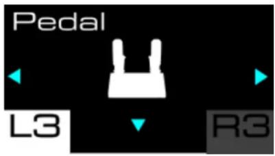
Type of pedal set

This screen lets you select the type of pedal set being used. There are two types of pedal sets to choose from:
- T3PM: for the T2PM*, T3PA* and T3PM pedal sets (without a Load Cell force sensor);
- T-LCM: for the T-LCM Pedals* pedal set (with a Load Cell force sensor).
Pedal set configuration
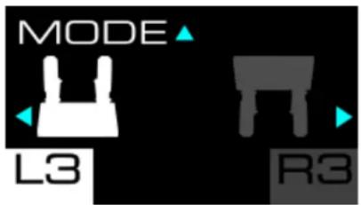
This screen lets you select the pedal set configuration.
There are two positions to choose from:
- (default): normal position;
- Inverted position.

- The inverted position is only available with a 3-pedal pedal set.
- In the inverted position, the accelerator and clutch pedals are reversed.
Resetting the settings
flowchart
graph TD
    A["LED +2"] --> B["LCD +1"]
    B --> C["Serial Number 24414047 40066821"]
    C --> D["T 26°C"]
    D --> E["FW 04.31"]
    E --> F["BOOST +1"]
    F --> G["FORCE 65%b"]
    G --> H["ROT 900"]
    H --> I["PEDAL"]
    I --> J["MODE T3PM"]
    J --> K["MODE"]
    K --> L["FACTORY RESET?"]
    L --> M["RESET? NO YES"]
    M --> N["L3 ✓"]

This screen lets you reset the settings for the racing wheel, pedal set, screen and telemetry.
To reset the settings:
- Press 🙏 The following screen is displayed:
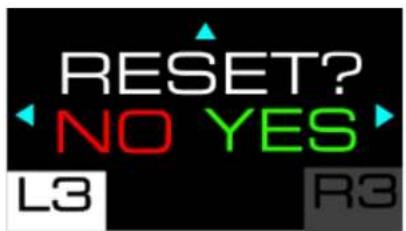
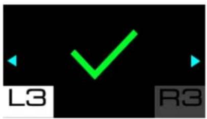
- Press to confirm the reset. When the settings have been reset, the following screen is displayed for five seconds:
Press to refuse the reset. The following screen is displayed:

Information about the racing wheel
flowchart
graph TD
    A["LED +2 L3"] --> B["LCD +1 L3"]
    B --> C["FW 04.31 L3"]
    C --> D["BOOST +1 L3"]
    D --> E["FORCE 85% L3"]
    E --> F["ROT 900 L3"]
    G["Serial Number 24414047 40066821 L3"] --> H["T 26°C L3"]
    I["Pedal L3"] --> J["MODE TOPM L3"]
    K["FACTORY RESET? L3"] --> L["RESET? NO YES L3"]
    M["MODE L3"] --> N["MODE"]
    O["√"] --> P["L3"]
Serial number
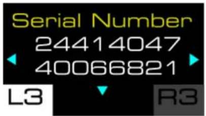
This screen displays the racing wheel's serial number.
Racing wheel temperature

This screen displays the racing wheel's temperature.
Telemetry submenu
The Telemetry submenu lets you select the telemetry information to be displayed on the screen: gear selected, speed, number of laps, position, session time, or engine speed (RPM).

To access the Telemetry submenu, press the ⏻ button (Settings), then press the R3 button.
In the Telemetry submenu, the following screen is displayed:
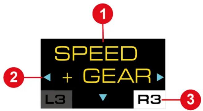
1 Type of information to be displayed on the screen
② Possible navigation in the submenu
3 Selected Telemetry submenu
During the game, the following screen is displayed:
1 Telemetry information
To navigate through the Telemetry submenu and select the telemetry information to be displayed:
- Use the directional buttons.
To confirm your selection:
- Press the ⚙ button (Settings).
You will exit the Telemetry submenu and the screen will display the selected telemetry information.

Telemetry and compatibility
The telemetry information is only displayed in games that are compatible with the Thrustmaster SDK.
The list of compatible games is available here:
https://support.thrustmaster.com/product/T248r/
(in the Games settings section). This list is updated regularly.
When telemetry information is not supported, the T248R logo is displayed on the screen.

Updating the firmware
To use the telemetry features, you may need to update the racing wheel's firmware.
To carry out the update:
- Go to
https://support.thrustmaster.com/product/t248r
- Download and install the My Thrustmaster Panel software available in the Software section and follow the instructions.

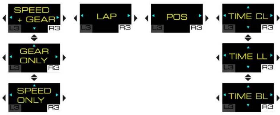
flowchart
graph TD
    A["SPEED + GEAR"] --> B["GEAR ONLY"]
    B --> C["SPEED ONLY"]
    D["LAP"] --> E["POS"]
    E --> F["TIME CL"]
    F --> G["TIME LL"]
    G --> H["TIME BL"]
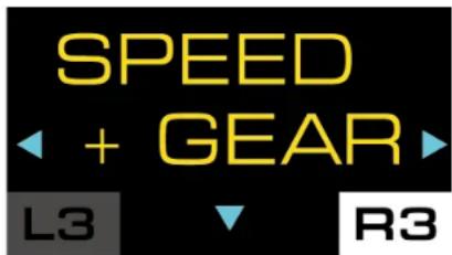
Speed + Gear (speed and selected gear)
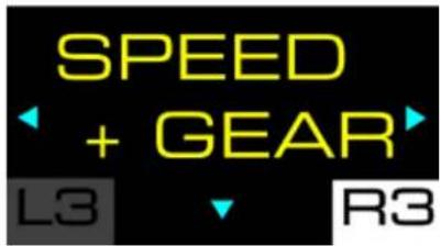
This screen lets you display the vehicle's speed and the selected gear when shifting gears.
Example of display:

Gear (gear)

This screen lets you display the selected gear.
Example of display:

Speed (speed)
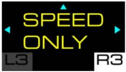
This screen lets you display the vehicle's speed.
Example of display:
248
Lap (lap)
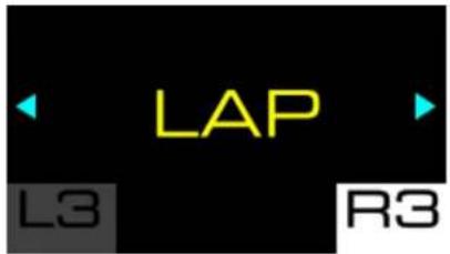
This screen lets you display the number of laps completed.
Example of display:

Position (position)

This screen lets you display the position in the ranking.
Example of display:

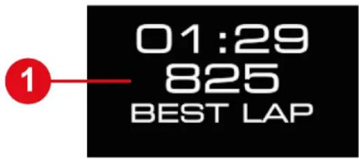
Time (time)
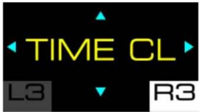
This screen lets you select the time display mode (TIME).
There are three modes to choose from:
– TIME CL: displays the current lap time (CURR LAP);
– TIME LL: displays the last lap time (LAST LAP);
– TIME BL: displays the personal best lap time (BEST LAP).
Examples of displays:
| TIME CL | TIME LL | TIME BL |
| 01:29 825 CURR LAP | 01:29 825 LAST LAP | 01:29 825 BEST LAP |

Use the ✕ directional buttons to select a mode, then press the ⏻ button (Settings) to confirm your selection.
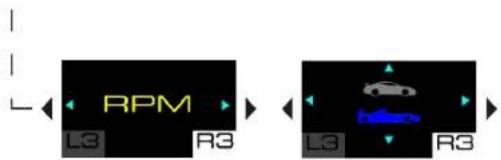
Engine speed
This screen lets you display the engine speed (RPM).
Example of display:
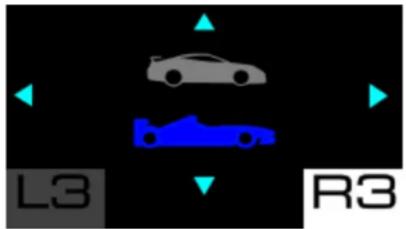
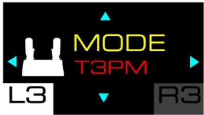
GT or Formula mode
natural_image
Two racing car icons with blue and gray coloring on black background, labeled L3 and R3 (no text or symbols on car bodies)This screen lets you select the display mode for the RPM LEDs. There are two modes to choose from:
- GT mode (red);
– Formula mode (blue, by default).

Use the ✕ directional buttons to select a mode, then press the ⏻ button (Settings) to confirm your selection.
12. Operation of the LEDs
The T248R racing wheel provides information that can be viewed via the LEDs: engine speed (RPM), flag (FLAG), and pit (PIT).
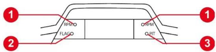
① Engine speed (RPM)
② Flag (FLAG)
③ Pit (PIT)

- To change the brightness of the LEDs, go to the Settings submenu and then to the Adjusting the LEDs' brightness screen.
- To change the display sequence of the RPM LEDs, go to the Telemetry submenu and then to the GT or Formula mode screen.

- The LEDs displaying race information only work in games that support telemetry. The list of compatible games is available here:
https://support.thrustmaster.com/product/T248r/ (in the Games settings section). This list is updated regularly.
- In games that do not support telemetry, the T248R logo is displayed on the screen.
Flag (FLAG) and pit (PIT)\*
The FLAG LED displays information about the flag, and the PIT LED displays information about the status of the pit.
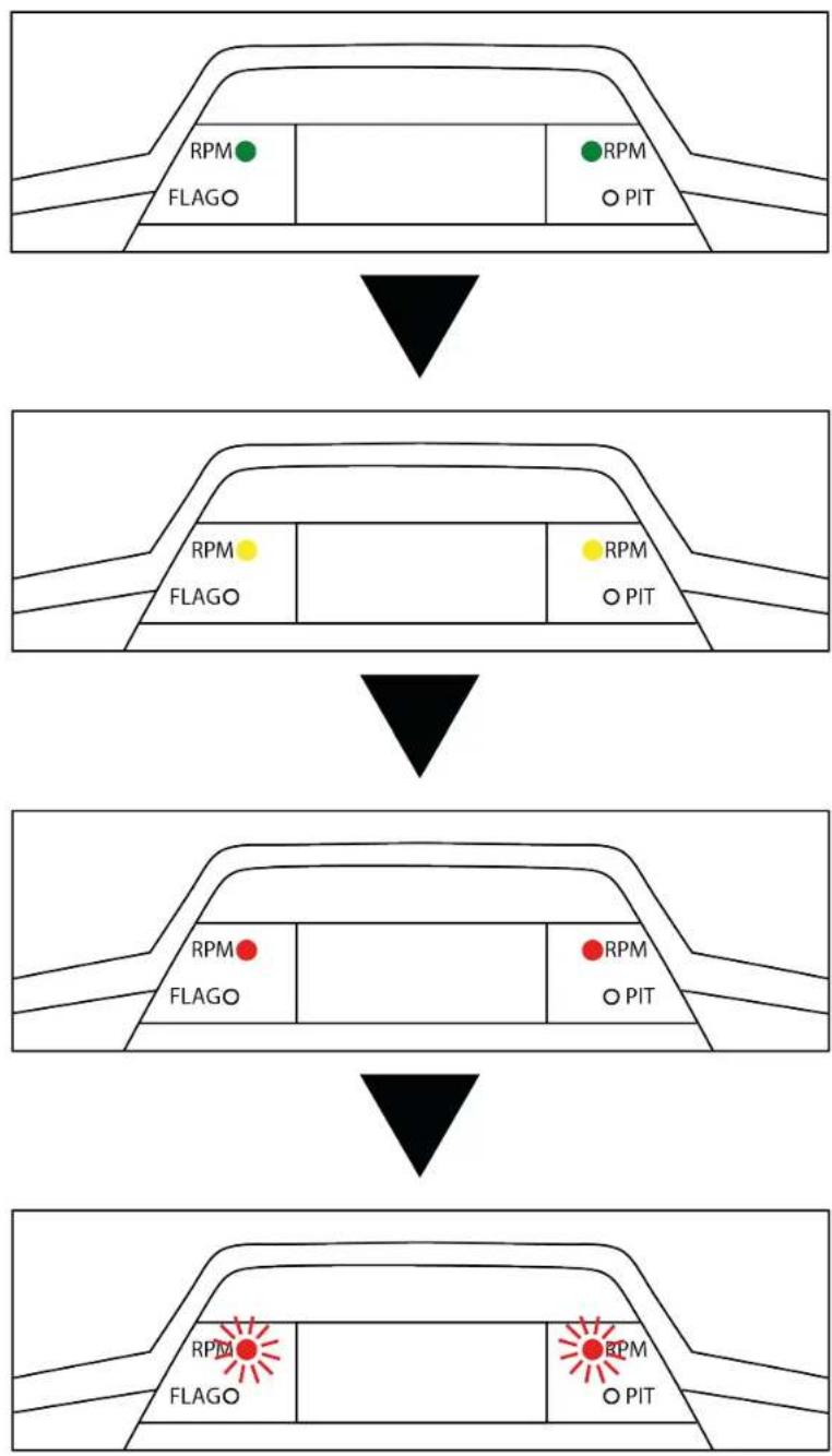
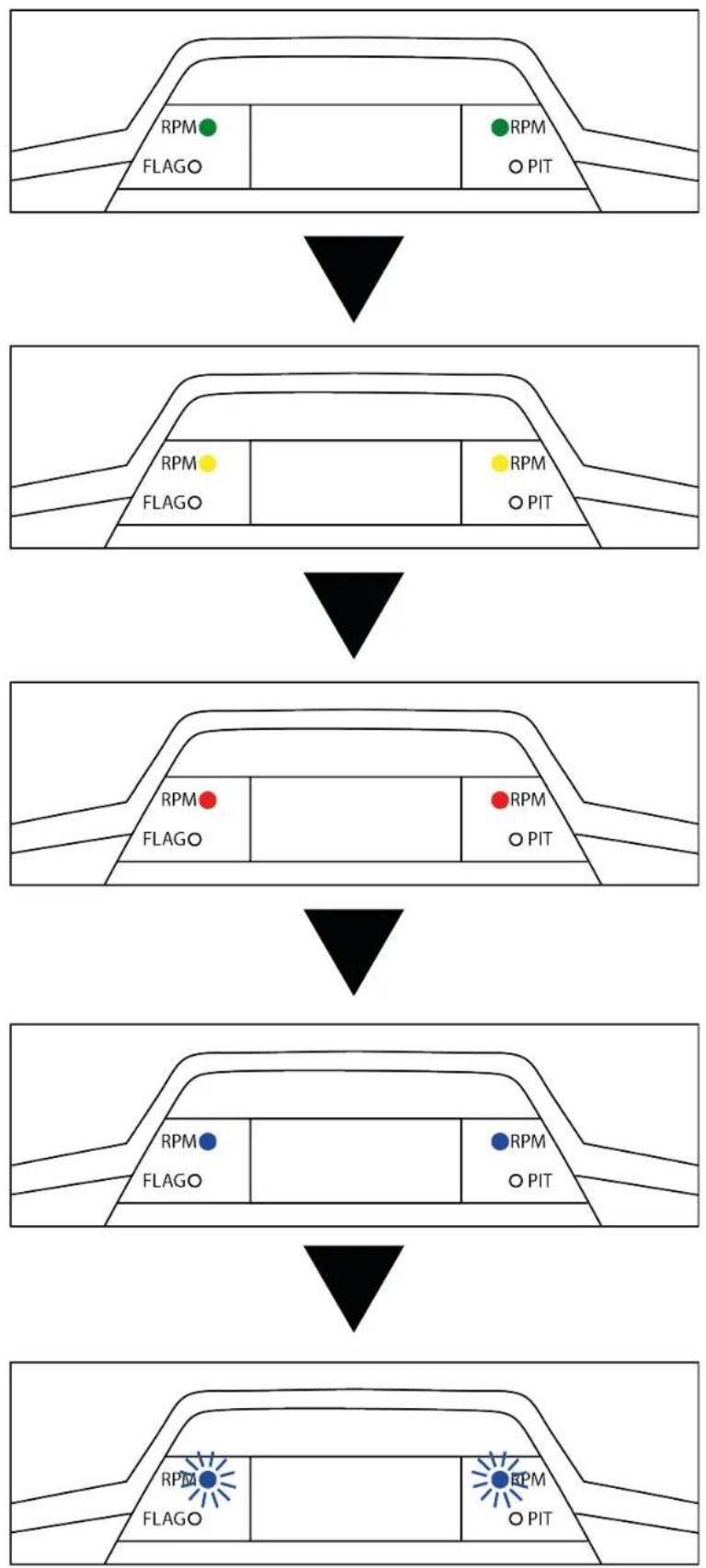
Engine speed (RPM)\*
The RPM LEDs display information about the engine speed.
Display sequence of the LEDs in GT mode:
flowchart
graph TD
    A["Front Panel"] --> B{Condition}
    B -->|Yes| C["State 1: RPM FLAGO"]
    B -->|No| D["State 2: RPM PIT"]
    C --> E["State 3: RPM FLAGO"]
    D --> F["State 4: RPM PIT"]
    E --> G["State 5: RPM FLAGO"]
    F --> H["State 6: RPM PIT"]
    G --> I["Final State"]
    H --> J["Final State"]
Display sequence of the LEDs in Formula mode:
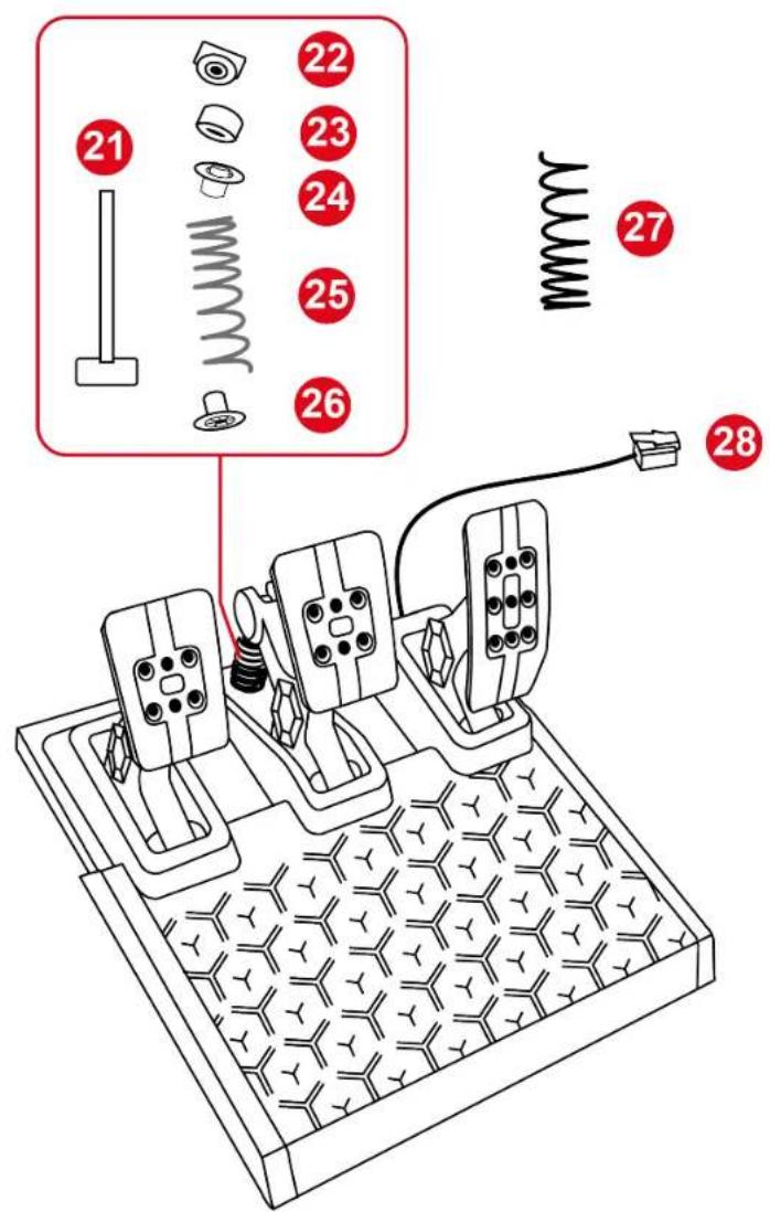
13. Adjusting the pedal set

To avoid any calibration problems, be sure to always disconnect your racing wheel's USB cable before making any adjustments to your pedal set.
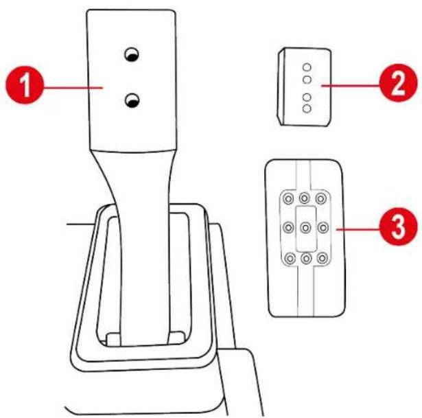
Each of the three pedals includes
- a pedal arm ①;
- a plastic head support ② placed between the head and the arm;
- a metal head ③ with multiple perforations (nine for the accelerator, six for the brake and six for the clutch).
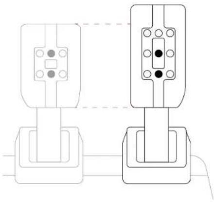
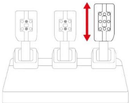
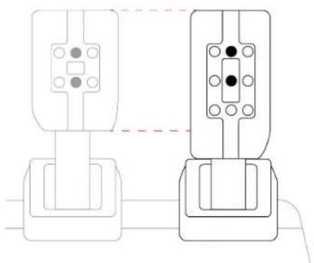
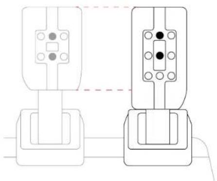
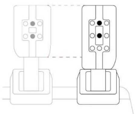
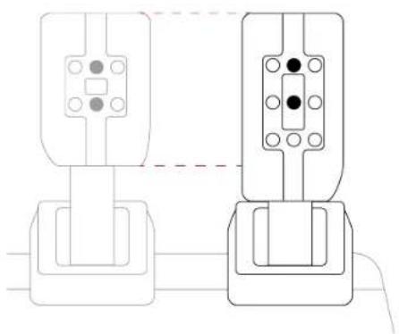
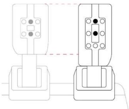
Adjusting the height of the accelerator pedal
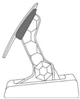
The accelerator pedal can be placed in two different positions.
High position (default):
natural_image
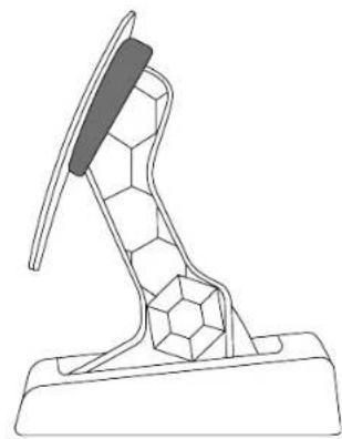
Pure mechanical component diagram showing two connected parts with mounting holes and a central shaft (no text or symbols)Low position:

natural_image
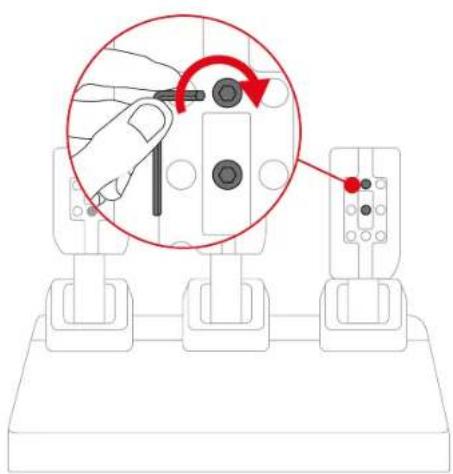
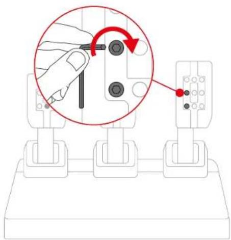
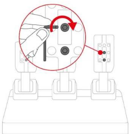
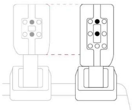
Pure electrical circuit lines without any symbols- Use the included 2.5 mm Allen key to unscrew the two screws holding the metal head and its support in place.
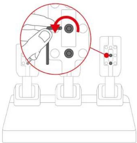
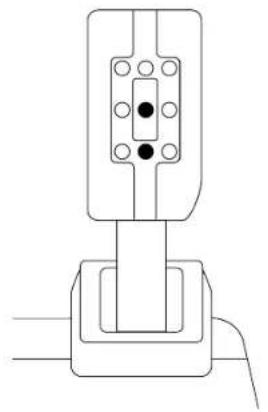
- Select the new metal head position.
natural_image
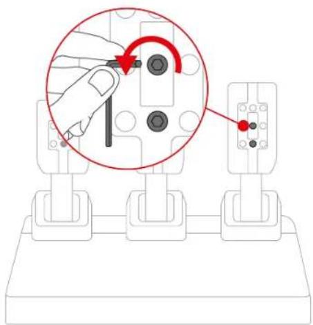
Diagram of three identical electrical connectors with a red double-headed arrow indicating vertical displacement (no text or symbols)- Reinsert and retighten the two screws holding the metal head and its support in place.
natural_image
Diagram showing a hand holding a screwdriver with a red circular arrow indicating rotation, next to three mechanical components (no text or symbols present)Adjusting the spacing of the pedals
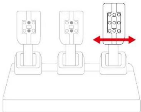
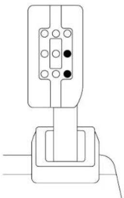
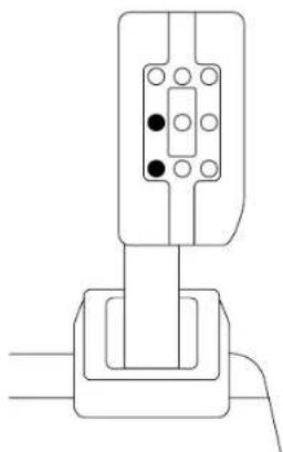
Each pedal can be placed in three different positions.
Example with the accelerator pedal:
In the center (default)
natural_image
Pure electrical circuit lines without any symbolsTo the left

natural_image
Pure mechanical assembly diagram without any text, numbers, or symbolsTo the right

natural_image
Pure electrical circuit lines without any symbols- Use the included 2.5 mm Allen key to unscrew the two screws holding the metal head and its support in place.

- Select the new metal head position.
natural_image
Diagram of three identical mechanical components with a red double-headed arrow indicating rotation or movement (no text or symbols present)- Reinsert and retighten the two screws holding the metal head and its support in place.
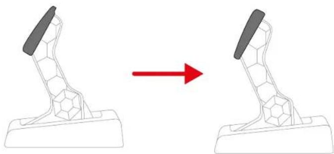
Adjusting the inclination of the pedals
Each pedal can be angled in two different positions.
Least inclined position (default):
natural_image
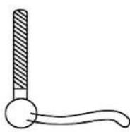
Line drawing of a mechanical component with a textured base and central blade (no text or symbols)Most inclined position:
natural_image
Line drawing of a mechanical lever or support structure with hexagonal base and curved handle (no text or symbols)- Use the included 2.5 mm Allen key to unscrew the two screws holding the metal head and its support in place.
- Rotate the plastic head support 180^ .
natural_image
Diagram showing a mechanical device before and after transformation, with no text or symbols present.- Reinsert and retighten the two screws holding the metal head and its support in place.
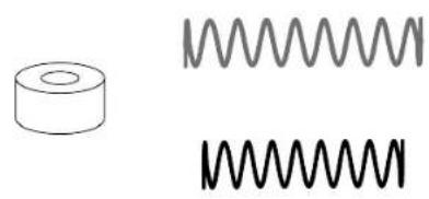
Modifying the brake pedal's resistance
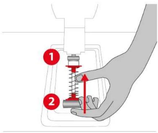
To adjust the brake pedal's resistance, an elastomer cushioning ring and two springs (silver: weak resistance; black: strong resistance) are included.
natural_image
Three abstract line drawings: a cylindrical object, two coiled springs, and one straight coil (no text or symbols)Four configurations are possible.
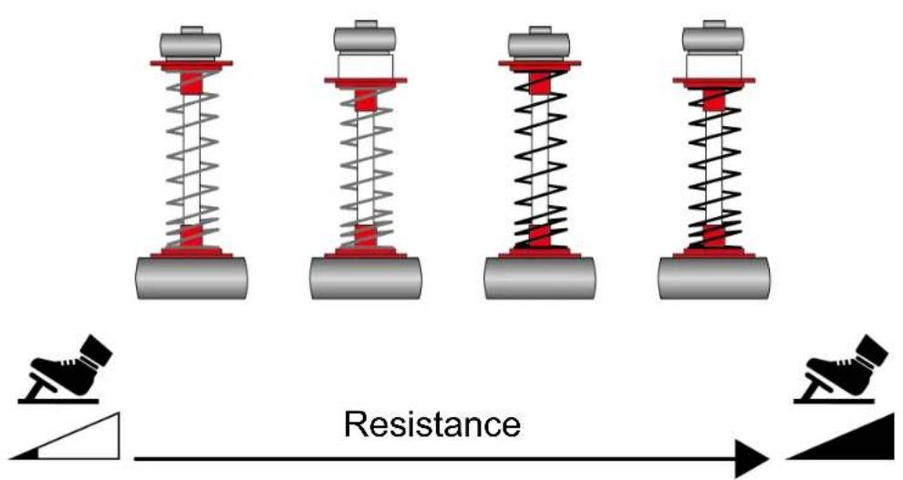
| Configuration | Resistance/Use | |
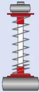 | Soft spring (silver) | Resistance: weakRecommended use: desk |
 | Soft spring (silver)+ cushioning ring | Resistance: medium (default)Recommended use: desk |
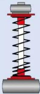 | Hard spring (black) | Resistance: strongRecommended use: pedal set support |
 | Hard spring (black)+ cushioning ring | Resistance: very strongRecommended use: cockpit |

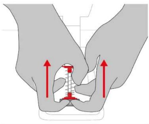
A video showing how to install the spring is available here:
https://support.thrustmaster.com/product/t248r
- To release the spring's retaining rod from its position, compress the spring using the lower plastic spacer.
natural_image
Illustration of two hands performing a medical or mechanical procedure with red arrows indicating upward motion (no text or symbols present)- Remove all of the parts comprising the brake pedal's spring.
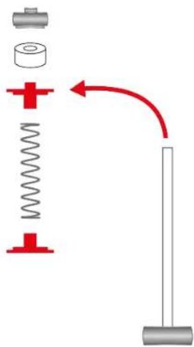
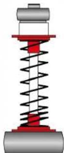
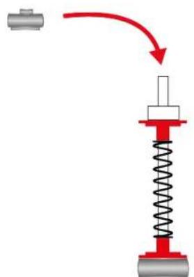
- Insert the parts comprising the brake pedal's spring onto the retaining rod in the following order: lower plastic spacer, spring of your choice, then upper plastic spacer.
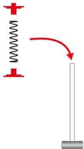
- (Optional) Insert the elastomer cushioning ring onto the retaining rod.
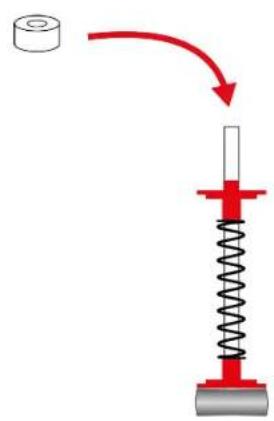
- Insert the upper retaining head with washer onto the retaining rod.
natural_image
Diagram showing a spring-mass system with a red arrow indicating motion (no text or symbols)- Insert the retaining rod at the back of the brake pedal, then compress the spring to insert the lower part of the retaining rod into its position.
14. FAQ and technical support
Do you have questions regarding the T248R racing wheel, or are you experiencing technical problems? If so, visit the Thrustmaster technical support website:
https://support.thrustmaster.com/product/t248r

THRUSTMASTER®

Pour consoles PlayStation®5, consoles PlayStation®4 et PC*
9. MAPPING POUR PC ....49
https://support.thrustmaster.com/product/T248r/
natural_image
Diagram of a car steering wheel with hands operating controls, enclosed in a green circular border (no text or symbols)natural_image
Technical diagram of a mechanical assembly with a magnified inset showing a detail (no text or symbols present)natural_image
Diagram of a mechanical device with a red upward arrow indicating motion or force (no text or symbols present)natural_image
Technical line drawing of a mechanical device with a rotating knob and rotating arm (no text or symbols)natural_image
Technical line drawing of a mechanical component with no visible text or symbols
natural_image
Technical line drawing of a three-part mechanical housing or enclosure with mounting holes and internal components (no text or symbols)7. Installation
Sur consoles PlayStation®4


*non fourni


https://support.thrustmaster.com/product/T248r
natural_image
Diagram showing a hand pointing to a device component with no visible text or symbolsnatural_image
Diagram showing a hand pointing to a device component with no visible text or symbolshttps://support.thrustmaster.com/product/T248r/

Type de pédalier

https://support.thrustmaster.com/product/T248r/
https://support.thrustmaster.com/product/t248r
natural_image
Two racing car icons (gray and blue) on black background with directional arrows, labeled L3 and R3 at bottom (no text or symbols on car bodies)flowchart
graph TD
    A["Top Section"] --> B["Mid Section"]
    B --> C["Bottom Section"]
    C --> D["Left Side: Fully Covered, with RPM, FLAGO, and O PIT marked"]
    D --> E["Right Side: Fully Covered, with RPM, FLAGO, and O PIT marked"]
    E --> F["Left Side: Fully Covered, with RPM, FLAGO, and O PIT marked"]
    F --> G["Bottom Section: Fully Covered, with RPM, FLAGO, and O PIT marked"]
natural_image
Pure mechanical assembly diagram showing two identical components with mounting holes and a central shaft (no text or symbols)Position basse :
natural_image
Pure electrical circuit lines without any symbolsnatural_image
Three identical electrical connector components mounted on a base, with one component highlighted by a red double-headed arrow (no text or symbols present)natural_image
Pure mechanical assembly diagram without any text, numbers, or symbolsÀ gauche

natural_image
Pure mechanical assembly diagram without any text, numbers, or symbolsÀ droite

natural_image
Pure electrical circuit lines without any symbolsnatural_image
Diagram of three identical mechanical components with mounting holes and a red double-headed arrow indicating rotation (no text or symbols)natural_image
Line drawing of a mechanical device with a handle and hexagonal base (no text or symbols)natural_image
Line drawing of a mechanical lever or support structure with hexagonal base and handle (no text or symbols)natural_image
Diagram showing a mechanical device before and after transformation, with no text or symbols present.natural_image
Three abstract line drawings: a cylindrical object, a coiled spring, and a straight coil (no text or symbols)https://support.thrustmaster.com/product/t248r
natural_image
Illustration of two hands performing a medical or mechanical procedure with red arrows indicating direction (no text or symbols present)natural_image
Diagram showing a spring-mass system with a red arrow indicating motion (no text or symbols)Consultez le site du support technique Thrustmaster :
https://support.thrustmaster.com/product/t248r

THRUSTMASTER®

https://support.thrustmaster.com/product/T248r/
natural_image
Simple line drawing of a curved structural component with two circular ends (no text or symbols)29
30
natural_image
Pure electrical circuit lines without any symbols31
natural_image
Simple black-and-white diagram of a rectangular device connected to a battery and wire (no text or symbols)32
natural_image
Pure electrical circuit lines without any symbols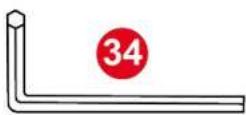
natural_image
Top-down line drawing of a car steering wheel with hands operating it, enclosed in a green circular border (no text or symbols)natural_image
Technical diagram of a mechanical assembly with a magnified inset showing a component detail (no text or symbols)natural_image
Diagram of a medical device with a red upward arrow indicating motion or force (no text or symbols present)natural_image
Technical line drawing of a mechanical device with a rotating knob and rotating shaft (no text or symbols)https://support.thrustmaster.com/product/t248r
natural_image
Technical line drawing of a device casing with labeled components (no text or symbols)
natural_image
Technical line drawing of three mechanical components with red circular annotations highlighting features (no text or symbols present)7. Installation
Auf PlayStation®4-Konsolen


natural_image
Diagram showing a red hand pointing to a device component with no visible text or symbolsnatural_image
Diagram showing a red hand pointing to a device component with no visible text or symbols
Typ des Pedalsets
https://support.thrustmaster.com/product/T248r/
https://support.thrustmaster.com/product/t248r
natural_image
Two car icons with blue and gray coloring on black background, labeled L3 and R3 (no text or symbols on the car bodies)https://support.thrustmaster.com/product/t248r
natural_image
Pure electrical circuit lines without any symbolsTiefe Position:

natural_image
Pure electrical circuit lines without any symbolsnatural_image
Diagram of three identical electrical connectors with a red double-headed arrow indicating vertical displacement (no text or symbols)natural_image
Pure technical line drawing of a mechanical assembly with no text or symbolsnatural_image
Pure mechanical assembly diagram without any text, numbers, or symbolsnatural_image
Pure electrical circuit lines without any symbolsnatural_image
Diagram of three identical mechanical components with a red double-headed arrow indicating rotation or movement (no text or symbols present)natural_image
Line drawing of a mechanical device with a handle and hexagonal base (no text or symbols)natural_image
Line drawing of a mechanical lever or support structure with hexagonal base and handle (no text or symbols)natural_image
Diagram showing a device being processed from a left-side component to a right-side component, with no text or symbols present.natural_image
Three abstract line drawings: a cylindrical object, two coiled springs, and one straight coil (no text or symbols)https://support.thrustmaster.com/product/t248r
natural_image
Illustration of hands performing a medical or anatomical procedure with red arrows indicating upward pressure points (no text or symbols present)natural_image
Diagram showing a spring-mass system with a red arrow indicating motion (no text or symbols)THRUSTMASTER®

Voor PlayStation®5-consoles, PlayStation®4-consoles en de PC*
Handleiding

https://support.thrustmaster.com/product/T248r/
natural_image
Top-down line drawing of a car steering wheel with hands operating controls, enclosed in a green circular border (no text or symbols)natural_image
Technical diagram of a mechanical assembly with a magnified inset showing a detail (no text or symbols)natural_image
Diagram of a medical device with a red upward arrow indicating force or movement (no text or symbols present)natural_image
Technical line drawing of a mechanical device with a rotating knob and rotating arm (no text or symbols)natural_image
Technical line drawing of a device casing with labeled components (no text or symbols)
natural_image
Technical line drawing of three mechanical components with mounting holes and red circular annotations (no text or symbols)7. Installatie
Op PlayStation®4-consoles

flowchart
graph TD
    A["Switch"] --> B["Device 1"]
    B --> C["Terminal Block 2"]
    C --> D["Terminal Block 3"]
    D --> E["Terminal Block 4"]
    E --> F["Terminal Block 5"]
    style A fill:#f9f,stroke:#333
    style B fill:#ccf,stroke:#333
    style C fill:#cfc,stroke:#333
    style D fill:#fcc,stroke:#333
    style E fill:#cff,stroke:#333
    style F fill:#ffc,stroke:#333


https://support.thrustmaster.com/product/t248r
My Thrustmaster Panel-software

natural_image
Diagram showing a hand pointing to a device component with no visible text or symbolsnatural_image
Diagram showing a hand pointing to a device component with no visible text or symbolshttps://support.thrustmaster.com/product/T248r/

Type pedaalset

https://support.thrustmaster.com/product/T248r/
https://support.thrustmaster.com/product/t248r
natural_image
Two car icons with blue and gray coloring on black background, labeled L3 and R3 (no text or symbols on the car bodies)https://support.thrustmaster.com/product/t248r
natural_image
Pure electrical circuit lines without any symbolsLage stand:
natural_image
Pure electrical circuit lines without any symbolsnatural_image
Diagram of three identical electrical connectors with a red double-headed arrow indicating vertical displacement (no text or symbols)natural_image
Diagram showing a hand holding a screwdriver with a red circular arrow indicating rotation, next to three mechanical components (no text or symbols present)natural_image
Pure mechanical assembly diagram without any text, numbers, or symbolsNaar links
natural_image
Pure technical line drawing of a mechanical assembly with no text or symbolsNaar rechts
natural_image
Pure electrical circuit lines without any symbolsnatural_image
Diagram of three identical mechanical components with a red double-headed arrow indicating rotation or movement (no text or symbols present)natural_image
Line drawing of a mechanical device with a handle and hexagonal base (no text or symbols)natural_image
Line drawing of a mechanical lever or support structure with hexagonal base and handle (no text or symbols)natural_image
Diagram showing a mechanical component before and after transformation, with no text or symbols present.natural_image
Three abstract line drawings: a cylindrical object, a coiled spring, and a wavy line (no text or symbols)https://support.thrustmaster.com/product/T248R
natural_image
Illustration of hands performing a medical or surgical procedure with red arrows indicating pressure points (no text or symbols present)
natural_image
Diagram showing a spring-mass system with a red arrow indicating motion direction (no text or symbols)14. FAQ
en
technische
ondersteuning
https://support.thrustmaster.com/product/t248r

THRUSTMASTER®

Per console PlayStation®5, console PlayStation®4 e PC*
Manuale d'uso

https://support.thrustmaster.com/product/T248r/
natural_image
Top-down line drawing of a car steering wheel with hands, enclosed in a green circular border (no text or symbols)natural_image
Technical diagram of a mechanical assembly with a magnified inset showing a detail (no text or symbols)natural_image
Diagram of a mechanical device with a red upward arrow indicating motion or force (no text or symbols present)natural_image
Technical line drawing of a mechanical device with a rotating knob and rotating shaft (no text or symbols)natural_image
Technical line drawing of a device casing with labeled components (no text or symbols)
natural_image
Technical diagram of a mechanical housing with three internal compartments and mounting holes (no text or labels)7. Installazione
Su console PlayStation®4


*Non inclusa


https://support.thrustmaster.com/product/t248r
II software My Thrustmaster Panel
natural_image
Diagram showing a hand pointing to a device component with no visible text or symbolsnatural_image
Diagram showing a hand pointing to a device component with no visible text or symbolshttps://support.thrustmaster.com/product/T248r/

Boost + 1 (FFB 2) e Boost + 2 (FFB 3)
Tipo di pedaliera

To reset the settings:
https://support.thrustmaster.com/product/T248r/
https://support.thrustmaster.com/product/t248r
natural_image
Two racing car icons (gray and blue) on black background with directional arrows, labeled L3 and R3 at bottom (no text or symbols on car bodies)natural_image
Pure technical line drawing of two mechanical components with mounting holes and connecting rods (no text or symbols)Posizione bassa:

natural_image
Pure electrical circuit lines without any symbolsnatural_image
Diagram of three identical electrical connectors with a red double-headed arrow indicating vertical displacement (no text or symbols)natural_image
Pure electrical circuit lines without any symbolsA sinistra

natural_image
Pure mechanical assembly diagram without any text, numbers, or symbolsA destra
natural_image
Pure electrical circuit lines without any symbolsnatural_image
Diagram of three identical mechanical components with mounting brackets and a central component, showing directional arrows (no text or symbols)natural_image
Line drawing of a mechanical device with a handle and hexagonal base (no text or symbols)natural_image
Line drawing of a mechanical lever or support structure with hexagonal base and handle (no text or symbols)natural_image
Diagram showing a mechanical component before and after transformation, with no text or symbols present.natural_image
Three abstract line drawings: a cylindrical object, two wavy lines, and a black zigzag line (no text or symbols)https://support.thrustmaster.com/product/t248r
natural_image
Illustration of two hands performing a medical or surgical procedure with red arrows indicating pressure or force direction (no text or symbols present)
natural_image
Diagram showing a spring-mass system with a red arrow indicating motion (no text or symbols)THRUSTMASTER®

Para consolas PlayStation®5, consolas PlayStation®4 y PC*
Manual del usuario

https://support.thrustmaster.com/product/T248r/
natural_image
Top-down line drawing of a car steering wheel with hands operating controls, enclosed in a green circular border (no text or symbols)natural_image
Technical diagram of a mechanical assembly with a magnified inset showing a component detail (no text or symbols)natural_image
Diagram of a medical device with a red upward arrow indicating motion or force (no text or symbols present)natural_image
Technical line drawing of a mechanical device with a rotating knob and rotating shaft (no text or symbols)natural_image
Technical line drawing of a mechanical component with no visible text or symbols
natural_image
Technical diagram of three mechanical components with red circular annotations indicating features (no text or symbols present)7. Instalación
En consolas PlayStation®4


https://support.thrustmaster.com/product/t248r
Software My Thrustmaster Panel

natural_image
Diagram showing a hand pointing to a device component with no visible text or symbolsnatural_image
Diagram showing a hand pointing to a device component with no visible text or symbolshttps://support.thrustmaster.com/product/T248r/

Tipo de pedales
https://support.thrustmaster.com/product/T248r/
https://support.thrustmaster.com/product/t248r
natural_image
Two car icons with blue and gray coloring on black background, labeled L3 and R3 (no text or symbols on the car bodies)① Velocidad del motor (RPM)
② Bandera (FLAG)
③ Boxes (PIT)

natural_image
Pure electrical circuit lines without any symbolsPosición baja:
natural_image
Pure electrical circuit lines without any symbolsnatural_image
Diagram of three identical electrical connectors with a red double-headed arrow indicating vertical displacement (no text or symbols)natural_image
Pure mechanical assembly diagram without any text, numbers, or symbolsA la izquierda

natural_image
Pure mechanical assembly diagram without any text, numbers, or symbolsA la derecha

natural_image
Pure electrical circuit lines without any symbolsnatural_image
Diagram of three identical mechanical components with a red double-headed arrow indicating rotation or movement (no text or symbols present)natural_image
Line drawing of a mechanical device with hexagonal base and curved top (no text or symbols)natural_image
Line drawing of a mechanical lever or support structure with hexagonal base and central blade (no text or symbols)natural_image
Diagram showing a mechanical component before and after transformation, with no text or symbols present.natural_image
Three abstract line drawings: a cylindrical object, a coiled spring, and a wavy line (no text or symbols)https://support.thrustmaster.com/product/t248r
natural_image
Illustration of hands performing a medical or surgical procedure with red arrows indicating pressure points (no text or symbols present)natural_image
Diagram showing a spring-mass system with a red arrow indicating motion (no text or symbols)https://support.thrustmaster.com/product/t248r

THRUSTMASTER®

Para consolas PlayStation®5, consolas PlayStation®4 e PC*
Manual do Utilizador

https://support.thrustmaster.com/product/T248r/
natural_image
Line drawing of a car steering wheel with hands operating controls, enclosed in a green circular border (no text or symbols)natural_image
Technical diagram of a mechanical assembly with a magnified inset showing a detail (no text or symbols)natural_image
Diagram of a medical device with a red upward arrow indicating force or movement (no text or symbols present)natural_image
Technical line drawing of a mechanical device with a rotating knob and rotating arm (no text or symbols)6. Instalar o volante e o conjunto de pedais num suporte\* ou cockpit\*

https://support.thrustmaster.com/product/t248r (na secção Manual).

natural_image
Technical line drawing of a mechanical component with no visible text or symbols
natural_image
Technical diagram of three mechanical components with red circular annotations indicating features (no text or symbols present)7. Instalação
Em consolas PlayStation®4


https://support.thrustmaster.com/product/t248r
- Quando o controlador tiver sido instalado, reinicie o PC.
- Desligue o cabo USB-C/USB-A do PC.
Software My Thrustmaster Panel

Thrustmaster Advanced Racer.
natural_image
Diagram showing a hand pointing to a device component with no visible text or symbolsnatural_image
Diagram showing a hand pointing to a device component with no visible text or symbolshttps://support.thrustmaster.com/product/T248r/

Boost + 1 (FFB 2) e Boost + 2 (FFB 3)
Este ecrã permite-lhe selecionar o tipo de conjunto de pedais utilizado. Há dois tipos de conjuntos de pedais à escolha:
https://support.thrustmaster.com/product/t248r
natural_image
Two racing car icons (gray and blue) on black background with directional arrows, labeled L3 and R3 at bottom (no text or symbols on car bodies)1 Velocidade do motor (RPM)
② Bandeira (FLAG)
③ Ida à box (PIT)

Ajustar a altura do pedal do acelerador
natural_image
Pure electrical circuit lines without any symbolsPosição baixa:
natural_image
Pure electrical circuit lines without any symbolsnatural_image
Diagram of three identical electrical connectors with a red double-headed arrow indicating vertical displacement (no text or symbols)natural_image
Diagram showing a hand holding a screwdriver with a red circular arrow indicating rotation, next to three mechanical components (no text or symbols present)natural_image
Pure mechanical assembly diagram without any text, numbers, or symbolsÀ esquerda

natural_image
Pure mechanical assembly diagram without any text, numbers, or symbolsÀ direita

natural_image
Pure electrical circuit lines without any symbolsnatural_image
Diagram of three identical mechanical components with a red double-headed arrow indicating rotation or movement (no text or symbols present)natural_image
Line drawing of a mechanical device with a handle and hexagonal base (no text or symbols)natural_image
Line drawing of a mechanical lever or support structure with hexagonal base and handle (no text or symbols)natural_image
Diagram showing a device being processed from a left-side view, with a red arrow indicating the process (no text or symbols present)natural_image
Three abstract line drawings: a cylindrical object, a coiled spring, and a wavy line (no text or symbols)https://support.thrustmaster.com/product/t248r
natural_image
Illustration of hands performing a medical or anatomical procedure with red arrows indicating direction (no text or symbols present)
natural_image
Diagram showing a spring-mass system with a red arrow indicating motion (no text or symbols)THRUSTMASTER®

- Содержимое коробки

natural_image
Diagram of a steering wheel with hands operating controls, enclosed in a green circular border (no text or symbols)natural_image
Technical diagram of a mechanical assembly with a magnified inset showing a detail (no text or symbols)natural_image
Diagram of a medical device with a red upward arrow indicating force or movement (no text or symbols present)natural_image
Technical line drawing of a mechanical device with rotating arm and base (no text or symbols)natural_image
Technical line drawing of a device casing with labeled components (no text or symbols)
natural_image
Technical diagram of three mechanical components with red circular annotations highlighting features (no text or symbols present)7. Установка


natural_image
Diagram showing a hand pointing to a device panel with a circle and multiple buttons (no text or symbols)https://support.thrustmaster.com/product/T248r/
https://support.thrustmaster.com/product/T248r/
natural_image
Diagram showing a hand pointing to a device panel with a circle and multiple buttons (no text or symbols)https://support.thrustmaster.com/product/T248r/
https://support.thrustmaster.com/product/T248r/
https://support.thrustmaster.com/product/T248r/

Boost + 1 (FFB 2) и Boost + 2 (FFB 3)
https://support.thrustmaster.com/product/T248r/
natural_image
Two racing car icons (gray and blue) on black background with directional arrows, labeled L3 and R3 at bottom (no text or symbols on car bodies)natural_image
Pure electrical circuit lines without any symbolsНизкое положение:
natural_image
Pure electrical circuit lines without any symbolsnatural_image
Three identical electrical connector components mounted on a base, with one component highlighted by a red double-headed arrow (no text or symbols present)natural_image
Pure electrical circuit lines without any symbolsВлево

natural_image
Pure mechanical assembly diagram without any text, numbers, or symbolsВправо

natural_image
Pure electrical circuit lines without any symbolsnatural_image
Diagram of three identical mechanical components with a red double-headed arrow indicating rotation or movement (no text or symbols present)natural_image
Line drawing of a mechanical device with hexagonal base and curved top (no text or symbols)natural_image
Line drawing of a mechanical lever or support structure with hexagonal base and handle (no text or symbols)natural_image
Diagram showing a device being processed from a left-side view, with a red arrow indicating the process (no text or symbols present)natural_image
Three abstract line drawings: a cylindrical object, two coiled springs, and one straight coil (no text or symbols)https://support.thrustmaster.com/product/t248r
natural_image
Illustration of hands performing a medical or anatomical procedure with red arrows indicating direction (no text or symbols present)natural_image
Diagram showing a spring-mass system with a red arrow indicating motion (no text or symbols)https://support.thrustmaster.com/product/t248r

THRUSTMASTER®

Pro konzole PlayStation®5, konzole PlayStation®4 a PC*
Uživatelský manuál

https://support.thrustmaster.com/product/T248r/
1. Obsah boxu

2. Vlastnosti

natural_image
Top-down line drawing of a car steering wheel with hands, enclosed in a green circular border (no text or symbols)natural_image
Technical diagram of a mechanical assembly with a magnified inset showing a detail (no text or symbols present)natural_image
Diagram of a medical device with a red upward arrow indicating force or movement (no text or symbols present)natural_image
Line drawing of a mechanical device with a rotating knob and curved arm (no text or symbols)natural_image
Technical line drawing of a device casing with internal components and mounting holes (no text or symbols)
natural_image
Technical diagram of three mechanical components with red circular annotations indicating features (no text or symbols present)7. Instalace
Na konzole PlayStation®4


Software My Thrustmaster Panel

natural_image
Diagram showing a hand pointing to a device component with no visible text or symbolsnatural_image
Diagram showing a hand pointing to a device component with no visible text or symbolshttps://support.thrustmaster.com/product/T248r/

Boost + 1 (FFB 2) a Boost + 2 (FFB 3)
Typ pedálové sady

https://support.thrustmaster.com/product/t248r
natural_image
Two car icons with blue and gray coloring on black background, labeled L3 and R3 (no text or symbols on the car bodies)1 Otáčky motoru (RPM)
② Vlajka (FLAG)
③ Box (PIT)

https://support.thrustmaster.com/product/T248r/
natural_image
Pure electrical circuit lines without any symbolsNízká poloha:
natural_image
Pure mechanical assembly diagram showing two components with mounting holes and a dashed line indicating alignment (no text or symbols)natural_image
Diagram of three identical electrical connectors with a red double-headed arrow indicating vertical displacement (no text or symbols)natural_image
Diagram showing a hand holding a screwdriver with a red circular arrow indicating rotation, next to a mechanical component (no text or symbols present)natural_image
Pure mechanical assembly diagram without any text, numbers, or symbolsVlevo

natural_image
Pure electrical circuit lines without any symbolsVpravo

natural_image
Pure electrical circuit lines without any symbolsnatural_image
Diagram of three identical mechanical components with a red double-headed arrow indicating rotation or movement (no text or symbols present)natural_image
Line drawing of a mechanical component with a hexagonal base and curved top (no text or symbols)natural_image
Line drawing of a mechanical lever or support structure with hexagonal base and curved handle (no text or symbols)natural_image
Diagram showing a mechanical component before and after transformation, with no text or symbols present.natural_image
Illustration of two hands performing a medical or mechanical procedure with red arrows indicating direction (no text or symbols present)natural_image
Diagram showing a spring-mass system with a red arrow indicating motion direction (no text or symbols)https://support.thrustmaster.com/product/t248r

THRUSTMASTER®

Motor devri (RPM)*......87
- PEDAL SETİNİN AYARLANMASI .....90
https://support.thrustmaster.com/product/T248r/
1. Kutu içeriği

2. Özellikler

natural_image
Top-down line drawing of a car steering wheel with hands operating controls, enclosed in a green circular border (no text or symbols)natural_image
Technical diagram of a mechanical assembly with a magnified inset showing a detail (no text or symbols present)natural_image
Diagram of a medical or laboratory device with a red upward arrow indicating force or movement (no text or symbols present)natural_image
Technical line drawing of a mechanical device with a rotating knob and lever (no text or symbols)natural_image
Technical line drawing of a device casing with labeled components (no text or symbols)
natural_image
Technical diagram of three mechanical components with red circular annotations indicating features (no text or symbols present)7. Kurulum
PlayStation®4 konsollarında


https://support.thrustmaster.com/product/t248r

natural_image
Diagram showing a hand pointing to a device component with no visible text or symbolshttps://support.thrustmaster.com/product/T248r/
https://support.thrustmaster.com/product/T248r/
natural_image
Diagram showing a hand pointing to a device component with no visible text or symbolshttps://support.thrustmaster.com/product/T248r/
https://support.thrustmaster.com/product/T248r/
https://support.thrustmaster.com/product/T248r/

Boost + 1 (FFB 2) ve Boost + 2 (FFB 3)
Force (genel Force Feedback)

Pedal setinin tipi

https://support.thrustmaster.com/product/T248r/