
DSM 408 - Range hood MIELE - Free user manual and instructions
Find the device manual for free DSM 408 MIELE in PDF.

| Product type | Electronic control module for Miele range hood |
| Brand | Miele |
| Model | DSM 408 |
| Dimensions (approx.) | Approx. 100 x 80 x 30 mm |
| Weight (approx.) | Approx. 0.2 kg |
| Power supply | 230 V / 50 Hz via connector on the hood's electronic unit |
| Main functions | Lighting control (on/off, dimmer if equipped) and potential-free contact for external device control |
| Switching capacity of the free contact | Max. 230 V / 2 (1) A |
| Grounding | Grounding cable included for compliant installation |
| Installation | By a qualified electrician, intended location on the hood or other suitable place |
| Maintenance and cleaning | Clean the housing with a dry cloth; do not use abrasive products |
| Safety | Electrical safety test (e.g. VDE 0701-1) mandatory after installation |
| Spare parts | Not available separately; contact Miele for replacement |
| Repairability | Only a qualified electrician may carry out repairs |
| General information | Designed exclusively for Miele range hoods; do not use on other appliances |
Frequently Asked Questions - DSM 408 MIELE
User questions about DSM 408 MIELE
0 question about this device. Answer the ones you know or ask your own.
Ask a new question about this device
Download the instructions for your Range hood in PDF format for free! Find your manual DSM 408 - MIELE and take your electronic device back in hand. On this page are published all the documents necessary for the use of your device. DSM 408 by MIELE.
USER MANUAL DSM 408 MIELE
Read the operating instructions carefully and retain them for future reference. Inappropriate use can lead to personal injury and damage to property. Miele cannot be held liable for injury or damage caused by non-compliance with these instructions.
Keep these instructions in a safe place and pass them on to any future owner.
The accessory must only be used with the Miele cooker hood for which it is intended. The cooker hood must only be used in line with its intended use. Please observe the operating instructions supplied with the cooker hood.
The connected components must be compatible with the control module and must be technically safe. Miele shall not accept warranty claims for any functional defects or damage caused by unsuitable components.
Unauthorised installation, maintenance and repairs can cause considerable danger for the user. Installation, maintenance and repairs may only be carried out by a qualified electrician who is familiar with and complies with the national regulations and any additional regulations of the local electricity provider.
Functional description
The control module enables the following:
- The cooker hood hob lighting can be switched on and off via a light switch integrated in the domestic installation.
If the cooker hood has a dimmer, dimming is also possible. - The potential-free connection is used to control another appliance depending on the switch status of the cooker hood fan.
Installation
Before installation, disconnect the cooker hood and the components to be connected from the power supply.
A position is provided on the cooker hood for installing the control module. This position is shown in the images at the end of these operating instructions. However, the control module may also be installed at another suitable location. Make sure that the control module housing is earthed. An earthing wire is provided.
- Remove the cooker hood if this is necessary to install the control module. Please observe the installation instructions supplied with the cooker hood.
If the control module will be difficult to access after installation, connect the relevant components before installation (see "Electrical connection").
Ensure that the connection cable and electrical connections for the connected components are laid correctly. They must not be kinked or crushed.
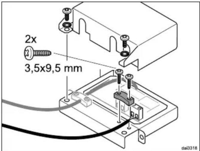
- Secure the control module with the screws supplied.
Insert the connection cable for the control module into the bushing on the cooker hood electronic module.
Electrical connection
Wiring diagram
The wiring diagram for connecting the components can be found at the end of these operating instructions.
Key:
ZLT.....Light switch
PK……………………………………… Potential-free contact
N1.....Cooker hood electronic module
N2. DSM control module
Connecting the light switch
The cooker hood hob lighting can be switched on and off and dimmed (depending on the appliance features) via a light switch integrated in the domestic installation. The lighting can also continue to be operated on the cooker hood.
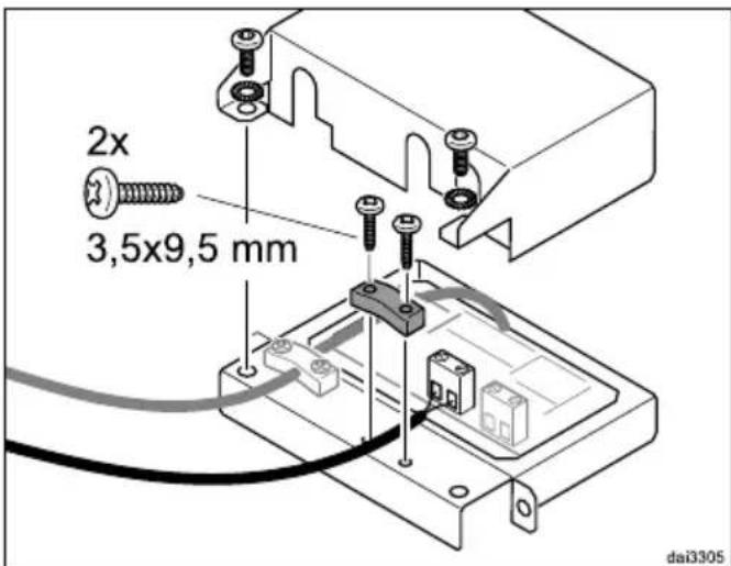
Remove the lid from the control module.
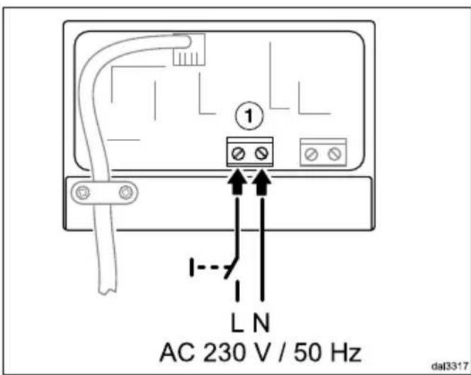
Connect the light switch to connection ①.
- Secure the cable with the strain relief provided.
- Close and screw on the lid of the control module.
If earthing cannot be ensured using the fixing screws, connect the earthing wire provided.
After all components have been installed, carry out an electrical safety check in accordance with local regulations (e.g. VDE 0701-1 in Germany).
Connecting the potential-free contact
The potential-free connection can be used to control other appliances depending on the switch status of the cooker hood fan.
When connecting ventilation appliances, the advice of a building regulations inspector must be sought.
The contact does not supply a defined voltage (potential-free). This means that the connection is suitable for universal application. The maximum switching capacity of the contact is 230 V/2 (1) A. The contact closes when the On/Off button for the cooker hood is switched on. The indicator light for the On/Off button and the indicator light for the second fan setting will come on.
Remove the lid from the control module.
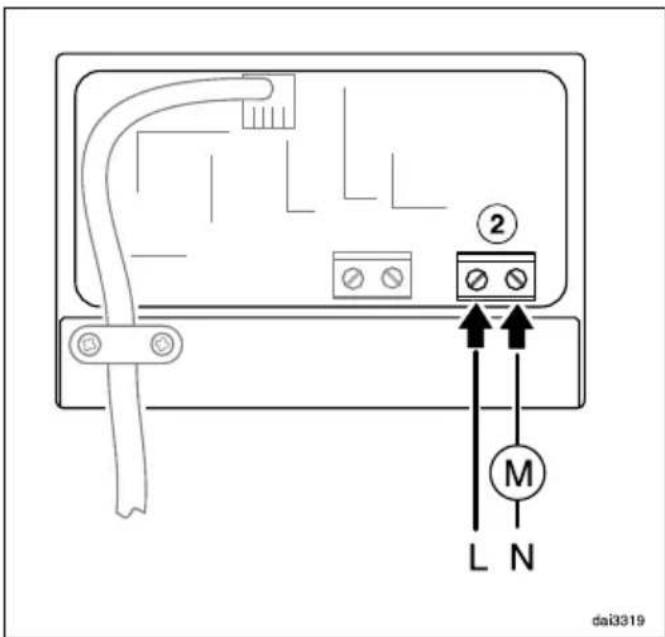
Connect the relevant components to connection ②.
- Secure the cable with the strain relief provided.
- Close and screw on the lid of the control module.
If earthing cannot be ensured using the fixing screws, connect the earthing wire provided.
After all components have been installed, carry out an electrical safety check in accordance with local regulations (e.g. VDE 0701-1 in Germany).
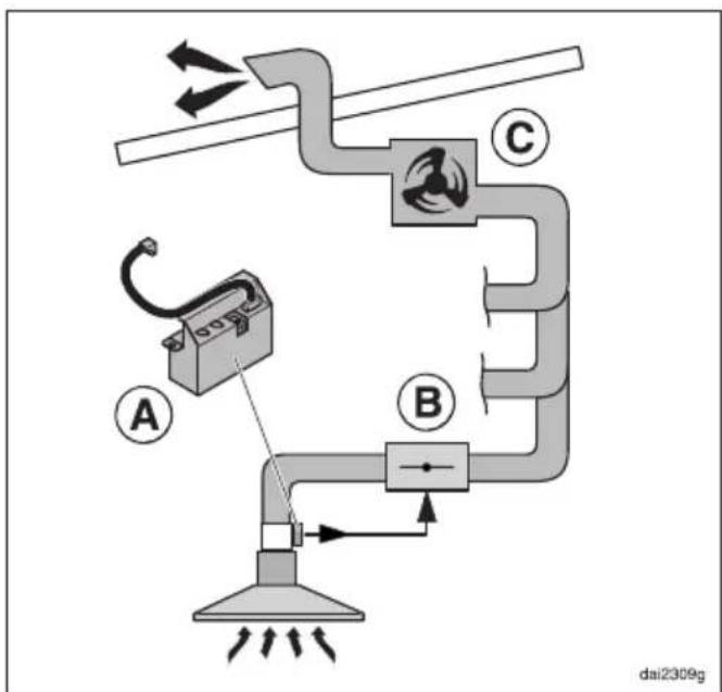
Central extraction unit
The potential-free contact of the control module A can, for example, be used in an EXT/EXTA model cooker hood that is connected to a central extraction unit. The contact can be used to actuate an electrically operated shut-off valve B, which is upstream of the central extraction unit.
The shut-off valve must be suitable for switching with a potential-free normally open contact.
The fan power is dependent on the fan used () and the design of the extraction system. The fan power is not controlled via the cooker hood control elements.
The components in the central extraction unit are not part of the Miele delivery programme.
If in any doubt, ask your building regulations inspector prior to installation.

Brand : MIELE
Model : DSM 408
Category : Range hood