
DAG500 - Range hood MIELE - Free user manual and instructions
Find the device manual for free DAG500 MIELE in PDF.

| Product Type | Downdraft Range Hood |
| Brand | Miele |
| Model | DAG500 |
| Power Supply | 120 V AC, 60 Hz, 15 A |
| Total Connected Load | 346 W (with internal DAG 600 blower) / 216 W (with external DAG 1000 blower) |
| Blower Compatibility | Internal DAG 600 or External DAG 1000 (optional accessories) |
| Extraction Modes | Vented (air exhausted outside) or Recirculation (air cleaned and returned to kitchen) |
| Exhaust Connection Diameter | 6" (150 mm) with DAG 600; 10" (254 mm) with DAG 1000 |
| Power Levels | 3 levels (1-3) plus Booster (B) level |
| Delayed Shutdown | 15-minute timer |
| Lighting | Overhead cooktop lighting, 70% brightness automatically, can be switched to 100% |
| Canopy | Retractable, motorized extension/retraction |
| Control Type | Touch controls |
| Grease Filters | Reusable metal mesh, clean every 3-4 weeks or when indicator lights |
| Charcoal Filters | Optional for recirculation mode, replace every 6 months or when odors persist |
| Filter Saturation Indicator | Yes, for grease filters |
| Compatible Cooktops | Gas and electric; max gas output 73,800 BTU/hr total, 16,500 BTU/hr per burner |
| Minimum Safety Distance | Per local codes and cooktop manufacturer specifications |
| Installation | Flush-fit in countertop, requires cutout; includes support bracket for cooktop |
| Material | Stainless steel housing, glass control panel |
| Warranty | Refer to warranty booklet; MieleCare Extended Service Contract available in USA |
| Service | Miele Technical Service (USA: 800-999-1360) |
Frequently Asked Questions - DAG500 MIELE
User questions about DAG500 MIELE
0 question about this device. Answer the ones you know or ask your own.
Ask a new question about this device
Download the instructions for your Range hood in PDF format for free! Find your manual DAG500 - MIELE and take your electronic device back in hand. On this page are published all the documents necessary for the use of your device. DAG500 by MIELE.
USER MANUAL DAG500 MIELE
Operating and Installation Instructions Downdraft
natural_image
Black-and-white photo of a cooking pot with steam rising, no visible text or symbolsTo prevent accidents and damage to the appliance, you must read these instructions before installing the appliance and using it for the first time.
IMPORTANT SAFETY INSTRUCTIONS 3
Caring for the environment 11
Guide to the appliance.... 12
Description of functions 14
Operation.... 15
Extending/retracting the canopy, switching the blower on/off.... 15
Selecting the power level 15
Selecting the delayed shutdown time 15
Turning the overhead lighting on/off.... 15
Energy-saving tips.... 16
Cleaning and care 17
Stainless steel housing.... 17
Grease filters and edge extraction panel.... 18
OdorFree Charcoal Filter 20
Disposing of charcoal filters 20
Installation.... 21
Before installation.... 21
Installation parts 21
Appliance dimensions 22
Cabinet dimensions.... 24
Cutout for flush-fit installation 25
Support bracket 26
Vented mode 32
Recirculation mode 32
Air venting 33
Reducing Collar 34
Electrical connection 35
Grounding Instructions.... 35
Power supply.... 35
Electrical connection of an external blower 37
Service and warranty 38
Location of the data plate 38
MieleCare 38
Technical data 39
READ AND SAVE THESE INSTRUCTIONS
This appliance complies with current safety requirements. Improper use of the appliance can lead to personal injury and material damage.
Read all instructions before installing or using the appliance for the first time. Only use the appliance for its intended purpose.
Keep these operating instructions in a safe place and pass them on to any future user.
Appropriate use
CAUTION: For General Ventilating Use Only. Do Not Use To Exhaust Hazardous Or Explosive Materials And Vapors.
This appliance is intended for residential use only. Use only as described in these operating instructions.
This ventilation hood is not intended for outdoor use.
It must only be used to extract and clean vapors produced during cooking. Any other use occurs at the owner's own risk.
This appliance is suitable for installation above gas or electric cooking surfaces.
▶ Persons who lack physical, sensory or mental abilities, or experience with the appliance should not use it without supervision or instruction by a responsible person.
IMPORTANT SAFETY INSTRUCTIONS
Safety with children
As with any appliance, close supervision is necessary when used by children.
▶ Please supervise children in the vicinity of the hood and do not let them play with it.
Danger of suffocation! Ensure that any plastic wrappings, bags, etc. are disposed of safely and kept out of the reach of children.
Technical safety
▶ WARNING: TO REDUCE THE RISK OF FIRE, ELECTRIC SHOCK, OR INJURY TO PERSONS, OBSERVE THE FOLLOWING:
- Use this appliance only in the manner intended by the manufacturer. If you have questions, contact Miele.
- Before servicing or cleaning the appliance, switch power off at the service panel and lock the service disconnecting means to prevent power from being switched on accidentally. If the service disconnecting means cannot be locked, securely fasten a prominent warning device, such as a tag, to the service panel.
CAUTION: To Reduce The Risk Of Fire And Electric Shock Install This Rangehood Only With Internal Blower Miele DAG 600 Or External Blower Miele DAG 1000.
▶ Unauthorized installation, maintenance, and repairs can cause considerable danger for the user. Installation, maintenance, and repairs must only be carried out by a Miele authorized technician.
▶ A damaged ventilation hood can be dangerous. Always check for visible signs of damage. Never use a damaged ventilation hood.
IMPORTANT SAFETY INSTRUCTIONS
Be certain your appliance is properly installed and grounded by a qualified technician. To guarantee the electrical safety of this appliance, continuity must exist between the appliance and an effective grounding system. It is imperative that this basic safety requirement be met. If there is any doubt, have the electrical system of the house checked by a qualified electrician.
▶ Reliable and safe operation of this hood can only be guaranteed if it has been connected to the electrical supply.
To avoid damaging the ventilation hood, make sure that the connection data (voltage and frequency) on the data plate correspond to the building's power supply before connecting the appliance.
If in doubt, consult a qualified electrician.
Do not use a power bar or extension cord to connect the ventilation hood to electricity. These are a fire hazard and do not guarantee the required level of appliance safety.
▶ To ensure safe operation, only use the ventilation hood after it has been properly installed.
This ventilation hood may not be used in non-stationary locations (e.g. on a ship).
▶ Adequate ventilation must be provided when the hood is operated simultaneously with devices that burn gas or other fuels.
Only open the housing as described in the enclosed “Installation diagram” and in the “Cleaning and care” section of this manual. Under no circumstances should any other parts of the housing be opened.
Tampering with electrical connections or components and mechanical parts is highly dangerous to the user and can cause operation faults.
IMPORTANT SAFETY INSTRUCTIONS
▶ Defective components should be replaced by Miele original parts only. Only with these parts can safety of the appliance be assured as intended by the manufacturer.
▶ If the power cord is damaged, it must only be replaced by a qualified service technician.
During installation, maintenance, and repair work, the ventilation hood must be disconnected from the electrical supply. It is only completely isolated from the electricity supply if one of the following applies:
- The circuit breakers on the electrical service panel are tripped.
- The screw-type fuses on the electrical service panel have been removed.
- The power cord (if present) has been unplugged from the socket (pull the plug not the cord).
Correct use
Danger of crushing injuries! Do not reach into the motion range of the canopy while it is extending/retracting.
▶ WARNING: TO REDUCE THE RISK OF A COOKTOP GREASE FIRE:
- a) Never leave surface units unattended at high settings. Boilovers cause smoking and greasy spillovers may ignite. Heat oils slowly on low or medium settings.
- b) Always turn the hood on when cooking at a high heat.
– c) Clean the ventilation hood frequently. Grease should not be allowed to accumulate on the fan or filter.
– d) Use the proper pan size. Always use cookware appropriate for the size of the cooking area.
IMPORTANT SAFETY INSTRUCTIONS
▶ Never use an open flame beneath the ventilation hood.
To avoid the risk of fire, do not flambé or grill over an open flame. When turned on, the ventilation hood will draw any flames into the filter. Fat deposits may ignite.
▶ WARNING: TO REDUCE THE RISK OF INJURY TO PERSONS IN THE EVENT OF A COOKTOP GREASE FIRE, OBSERVE THE FOLLOWING*:
- a) SMOTHER FLAMES with a close fitting lid, cookie sheet, or metal tray then turn off the burner. BE CAREFUL TO PREVENT BURNS. If the flames do not go out immediately, EVACUATE AND CALL THE FIRE DEPARTMENT.
- b) NEVER PICK UP A FLAMING PAN - You may be burned.
- c) DO NOT USE WATER, including wet dishcloths or towels - a violent steam explosion will result.
-
d) Use a fire extinguisher ONLY if:
-
1) You have a class ABC extinguisher, and you know how to operate it.
- 2) The fire is small and contained in the area where it started.
- 3) The fire department is being called.
- 4) You can fight the fire with your back to an exit.
*Based on “Kitchen Fire Safety Tips” published by NFPA.
The ventilation hood may become damaged if exposed to excessive heat from a gas cooktop.
- When using the ventilation hood over a gas cooktop, ensure that any burners in use are always covered by cookware. Turn burners off when removing the cookware, even if doing so for just a short time.
- Select cookware that is suitable for the size of the burner.
- Adjust the flame so that it never extends up the sides of the cookware.
- Avoid overheating the cookware (e.g., when cooking with a wok).
IMPORTANT SAFETY INSTRUCTIONS
▶ Always turn the ventilation hood on whenever a burner is in use to prevent damage from condensation.
▶ Overheated oil and fat can ignite, causing fire damage to the ventilation system.
Do not leave cookware, pans, and deep fryers unattended when cooking with oil or fat. Similarly, never leave an open grill unattended when grilling.
▶ Fat and debris deposits impair the proper functioning of the ventilation hood.
To ensure that cooking vapors are properly cleaned, never use the ventilation hood without the grease filters in place.
▶ Please note that the heat rising from the stovetop during cooking can cause the ventilation hood to become very hot.
Do not touch the housing or the grease filters until the ventilation hood has cooled down.
Proper installation
▶ WARNING: TO REDUCE THE RISK OF FIRE, ELECTRIC SHOCK, OR INJURY TO PERSONS, OBSERVE THE FOLLOWING:
- a) Installation work and electrical wiring must be done by qualified person(s) in accordance with all applicable codes and standards, including fire-rated construction.
- b) Sufficient air is needed for combustion and exhausting of gases through the flue (chimney of fuel burning equipment to prevent back drafting. Follow the heating equipment manufacturer's guideline and safety standards such as those published by the National Fire Protection Association (NFPA) and the American Society for Heating, Refrigeration and Air Conditioning Engineers (ASHRAE), and the local code authorities.
– c) When cutting or drilling into the wall or ceiling, do not damage electrical wiring and other hidden utilities.
– d) Ducted hoods must always be vented to the outdoors.
IMPORTANT SAFETY INSTRUCTIONS
– e) Do not use this hood with any solid-state speed control device.
To determine whether a ventilation hood may be operated above your cooking appliance, please refer to the information provided by the appliance's manufacturer.
▶ Safety regulations prohibit the installation of a ventilation hood over solid fuel stoves.
Insufficient distance between the cooking appliance and the ventilation system can result in damage to the hood.
The minimum safety distances between the appliance and the bottom of the ventilation system specified in the “Installation” section must be maintained, unless the appliance's manufacturer or local building codes has indicated that a greater distance is required. If more than one cooking appliance is used beneath the ventilation system, and if different minimum safety distances apply for these appliances, you should use the greater distance.
Be sure to observe the information contained in the “Installation” section when mounting the ventilation hood.
▶ Metal parts can have sharp edges which may cause injury. Wear gloves to protect your hands from being cut.
When installing the exhaust duct, only use pipes or tubes made of non-flammable material. These can be obtained from your Miele dealer or from Miele Technical Service.
Exhaust air should not be vented into a chimney or vent flue which is otherwise in use and should not be channeled into ducting which ventilates rooms with fuel-burning installations.
If exhaust air is to be extracted into a chimney or ventilation duct no longer used for other purposes, seek professional advice.
▶ WARNING: TO REDUCE THE RISK OF FIRE USE ONLY METAL DUCTWORK.
IMPORTANT SAFETY INSTRUCTIONS
Cleaning and maintenance
There is a risk of fire if cleaning is not completed according to the instructions in this manual.
▶ Never use a steam cleaner to clean the ventilation hood. The steam can reach the electrical components and cause a short circuit.
Accessories
▶ Use only genuine original Miele parts. If parts or accessories from other manufacturers are used, the warranty will become void.
Disposal of the packing material
The cardboard box and packing materials protect the appliance during shipping. They have been designed to be biodegradable and recyclable.
Ensure that any plastic wrappings, bags, etc. are disposed of safely and kept out of the reach of children. Danger of suffocation!
Disposal of your old appliance
Electrical and electronic appliances contain valuable materials. They also contain certain substances, compounds and components which were essential for the proper functioning and safe use of the equipment. Handling these materials improperly by disposing of them in your household waste can be harmful to your health and the environment. Therefore, please do not dispose of your old appliance with regular household waste and follow local regulations on proper disposal.
Consult with local authorities, dealers or Miele in order to dispose of and recycle electrical and electronic appliances. Miele assumes no responsibility for deleting any personal data left on the appliance being disposed. Please ensure that your old appliance is kept away from children until removal. Observe safety requirements for appliances that may tip over or pose an entrapment hazard.
dal3799us
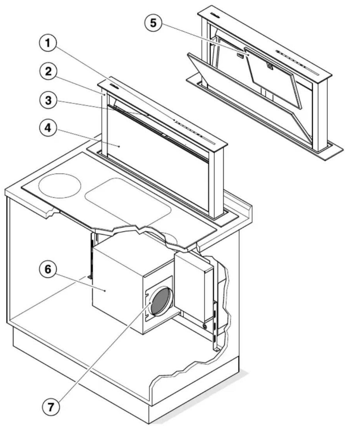
① Control panel
② Retractable canopy
③ Cooktop lighting
④ Edge extraction panel
⑤ Grease filter
⑥ DAG 600 blower unit Optional accessories
⑦ Exhaust connection
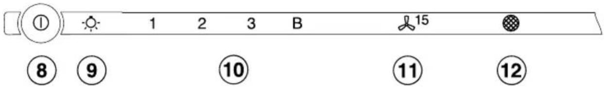
⑧ On/Off control for the retractable canopy and the blower
⑨ Overhead lighting button
⑩ Buttons for setting the blower power
⑪ Delayed shutdown button
⑫ Filter saturation indicator
The following functions are available on your ventilation hood, depending on the model:
Extraction mode
(requires DAG 600 internal blower as optional accessory)
The cooking vapors are drawn in by the ventilation system. The air is then passed via the edge extraction panel through the grease filters, cleaned and then directed outside.
Recirculation mode
(requires DAG 600 internal blower, conversion kit, and charcoal filter, available as optional accessories)
The air is drawn in via the edge extraction panel and cleaned first by the grease filters and then by charcoal filters. The air is then circulated back into the kitchen.
Operation with an external blower
(requires DAG 1000 external blower as optional accessory)
The external blower is mounted on the roof or an outside wall. It is connected to the ventilation system by a control cord and is operated by the ventilation system's control panel.
Extending/retracting the canopy, switching the blower on/off
Danger of crushing injuries! Do not reach into the motion range of the canopy while it is extending/ retracting.
Switch the blower on as soon as you start cooking. This is to ensure that vapors are captured right from the start.
■ Touch the On/Off control ⏻ until all symbols are lit up.
The canopy comes up. The blower switches on at power level 2, the cooktop lighting switches on at 70% brightness.
■ Touch the On/Off control ⏻ briefly to switch the blower off.
■ The blower can be switched on again by briefly touching one of the blower power level controls.
■ To retract the canopy, press the On/Off control ⏻ until all symbols are lit up.
The canopy retracts. All the symbols go out.
Selecting the power level
Power levels 1 to 3 are available for light to heavy cooking vapors and odors.
For strong vapors and odors that are temporarily produced when cooking, e.g., during searing, select the B booster level.
■ Select the power level required by tapping a button from 1 to B.
Reducing power of the booster level
The blower automatically switches back to power level 3 after 5 minutes.
Selecting the delayed shutdown time
It is advisable to run the blower for a few minutes after cooking has finished. This helps to neutralize any lingering vapors and odors in the air.
It also reduces the risk of residues accumulating in the ventilation hood and any resultant odors.
The delayed shutdown function enables the blower to continue running for a pre-determined time before switching itself off automatically.
■ After cooking has finished, press the delayed shutdown control ⚙15 while the blower is still running.
The blower will switch off after 15 minutes. The canopy remains extended.
■ If you touch the delayed shutdown control ⚙15 again, the blower will remain on.
Turning the overhead lighting on/off
■ The cooktop lighting is switched on and off when the deflector plate is extended and retracted.
The cooktop lighting switches on at 70 % brightness.
■ Touch the cooktop lighting control ⚙ to switch the lighting to 100 % brightness.
■ Touch the cooktop lighting control again to switch the lighting off.
This hood operates in a very efficient and energy-saving manner. The following will help you to save even more energy when using it:
- Ensure that there is sufficient ventilation in the kitchen when cooking. If there is insufficient air flow during extraction mode, the hood cannot operate efficiently, causing increased operating noise levels.
- Always cook with the lowest possible setting. This produces fewer cooking vapors so that you can use a lower hood power level and therefore benefit from reduced energy consumption.
- Check the power level selected on the hood. A lower power level is generally sufficient for the majority of cooking. Only use the booster level when necessary.
- When a large volume of cooking vapors are being produced, switch to a high power level in good time. This is more efficient than operating the hood for longer to try to capture cooking vapors that have already been distributed throughout the kitchen.
- Make sure that you switch off the hood after use.
- Clean or change the filters at regular intervals. Heavily soiled filters reduce performance, increase the risk of fire and are unhygienic.
⚠️ WARNING: TO REDUCE THE RISK OF FIRE, ELECTRIC SHOCK, OR INJURY TO PERSONS, OBSERVE THE FOLLOWING:
■ Before cleaning or servicing the hood, disconnect it from the power supply, see “IMPORTANT SAFETY INSTRUCTIONS”.
Stainless steel housing
General information
⚠️ The surfaces and control buttons are susceptible to scratching and chipping.
Observe the following cleaning instructions.
■ Clean all surfaces and control buttons using warm water and liquid dish soap. Apply with a sponge cloth.
⚠️ Make sure that no water gets into the interior of the hood.
Only use a damp cloth to clean the hood, especially in the control panel area.
■ After cleaning, dry the surfaces with a soft cloth.
Avoid the following:
- Cleaners containing soda, acid or chloride, or cleaners containing solvents
- Abrasive sponges, e.g. pot scourers or sponges which have been previously used with abrasive cleaning agents.
Special instructions for stainless steel surfaces
■ Stainless steel surfaces can also be cleaned using a non-abrasive stainless steel cleaner.
■ To prevent the surfaces from quickly becoming dirty again, we recommend treating them with a stainless steel care conditioner.
Apply sparingly over the entire area using a soft cloth.
Special instructions for glass surfaces
■ Glass surfaces can be cleaned using a cleaner specifically for use on glass.
Grease filters and edge extraction panel

Risk of fire!
Oversaturated grease filters are a fire hazard.
Clean the grease filters at regular intervals.
The edge extraction panel and the reusable metal grease filters in the appliance remove solid particles (grease, dust, etc.) from the kitchen vapors, preventing soiling of the hood.
The grease filters and the panel must be cleaned at regular intervals.
Heavily soiled grease filters hinder air extraction and will lead to increased levels of soiling in the ventilation hood and in the kitchen.
Cleaning intervals
Grease which has collected in the ventilation hood hardens over time and makes cleaning more difficult. It is therefore recommended that the edge extraction panel and the grease filters should be cleaned regularly (at least every 3–4 weeks) to avoid a build-up of grease.
After 30 operating hours, the grease filter symbol ⚙ will light up when the deflector plate is out to remind you to clean the edge extraction panel and the grease filters.
Removing the panel and grease filters
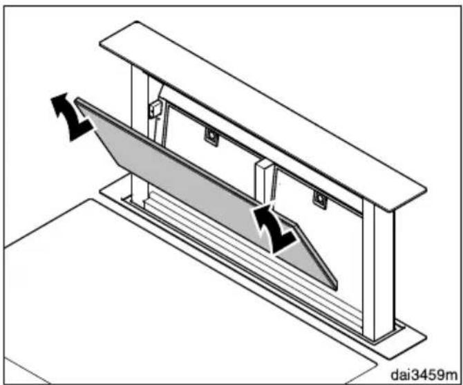
natural_image
Technical diagram of a mechanical assembly with directional arrows indicating motion or force (no text or symbols)■ The panel is held in place by magnets at the top. Pull the panel forwards by the upper edge, unhook it at the bottom and remove it.
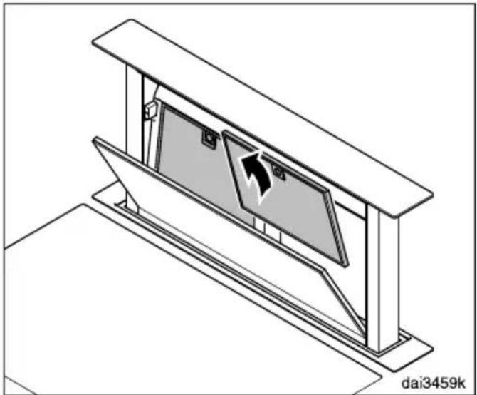
natural_image
Isometric technical diagram of a mechanical assembly with no visible text or symbols■ Open the grease filter retainer catch and remove the filters.
If charcoal filters are fitted on the back of the grease filters, they must be removed before cleaning (see "Charcoal filters").
Cleaning the panel
■ Follow the instructions under "Stainless steel housing."
The panel is not suitable for cleaning in a dishwasher.
Cleaning the grease filters by hand
■ Clean the filters with a soft nylon brush in a mild solution of hot water and dish soap. Do not use undiluted dish soap.
Unsuitable cleaning agents
Unsuitable cleaners can cause damage to the filter surfaces if used regularly. Do not use any of the following:
- Lime removers
- Abrasive powders or abrasive liquids
- Aggressive all-purpose cleaners and degreaser sprays
- Oven sprays
Cleaning the grease filters in a dishwasher
■ Place the grease filters upright or slightly inclined in the lower basket. Ensure the spray arm is not obstructed.
■ Use a commonly available household dishwashing detergent.
In a Miele dishwasher use the "Normal" program.
Depending on the detergent used, cleaning the filters in a dishwasher may cause the inside filter surfaces to become discolored. However, this will not affect the functioning of the grease filters in any way.
After cleaning
■ After cleaning, leave the filters on an absorbent surface to dry.
■ When removing the panel and filters for cleaning, also clean off any accessible oil or grease buildup from the housing. Doing so will prevent a fire hazard.
Resetting the filter saturation counter for the grease filters
Once cleaning is complete, the filter saturation counter must be reset.
■ With the deflector plate out, touch the grease filter control ☑ for approx. 3 seconds until the grease filter symbol ☑ goes out.
OdorFree Charcoal Filter
In recirculation mode with conversion kit DUU 2900, two charcoal filters are fitted into the recirculation unit. Refer to the Operating and Installation Instructions supplied.
Alternatively for the DA 6891: In recirculation mode with conversion kit DUU 151, two DKF 22-1 charcoal filters are fitted on the back of the grease filters. These are designed to absorb cooking odors.
Charcoal filters are available from your dealer or from Technical Service.
How to install/replace DKF 22-1 charcoal filters
■ Before installing or replacing the charcoal filters, the panel and the grease filters must first be taken out (see previous section for instructions on how to do this).
■ Remove the charcoal filter from its packaging.
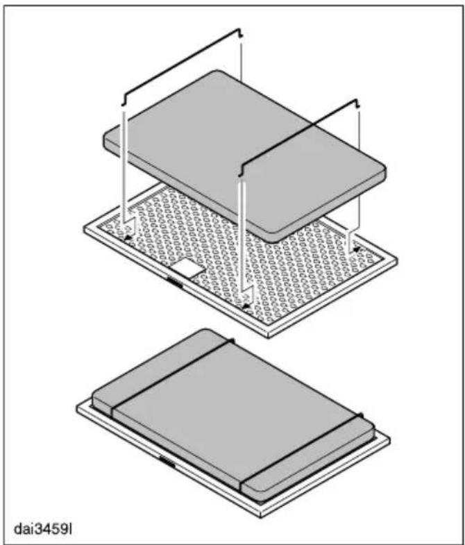
natural_image
Isometric diagram of two electronic components with circuitry and mounting holes, no text or symbols present■ Secure the charcoal filters to the back of the grease filters with the retainers provided.
■ Replace the grease filters and the panel.
When to change the OdorFree Charcoal Filter
■ Replace the charcoal filters when they no longer absorb kitchen odors effectively. They should, however, be replaced at least every 6 months.
Disposing of charcoal filters
■ Used charcoal filters can be disposed of with normal household waste.
Before installation
⚠️ Before installing the appliance, read all of the information contained in this chapter and also in the “IMPORTANT SAFETY INSTRUCTIONS” section.
Installation parts
natural_image
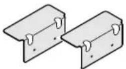
Technical line drawing of two metal structural beams with cutouts (no text or symbols)2 lower brackets
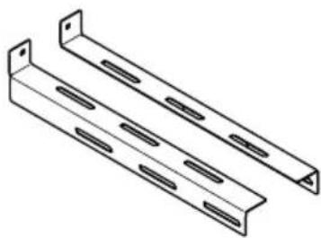
natural_image
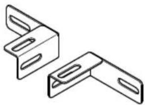
Technical line drawing of two L-shaped metal bracket components (no text or symbols)2 upper brackets
2 support brackets

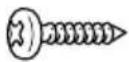
18 self-tapping screws ^1/8 " x ^3/8 " (3.5 x 9.5 mm)

6 screws ^3/16 " x ^5/16 " (M4 x 8 mm)
10 screws ^3/16 " x ^9/16 " (4 x 15 mm)
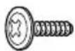
4 screws ^3/16 " x ^1/4 " (4 x 15 mm)
doi:459
dai3459q
Aufl-WinkelFaber
00034989
M4x8Fabor
00023673
2.966Faber
Appliance dimensions
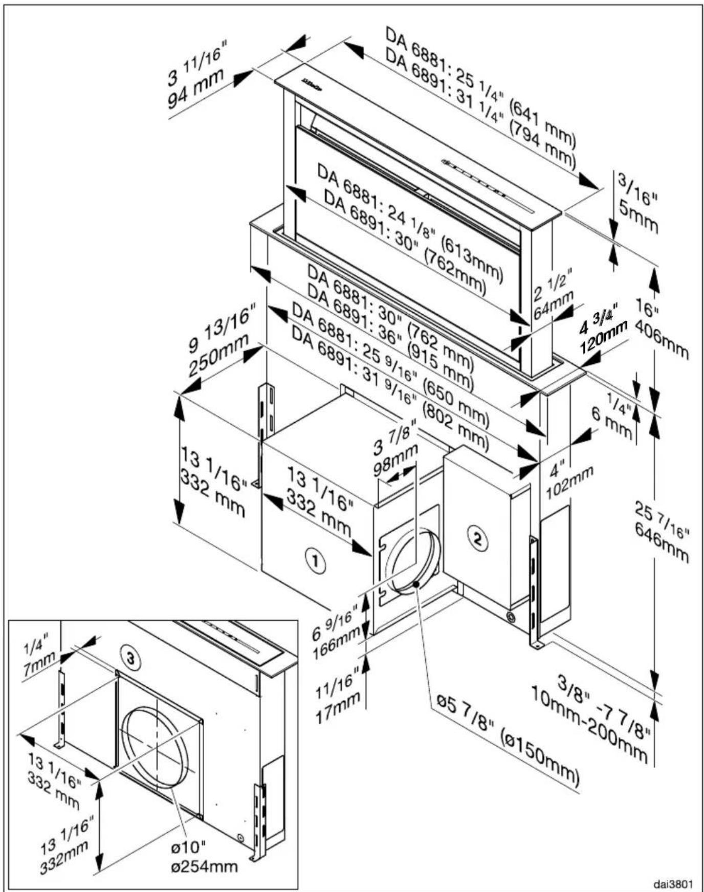
① The DAG 600 blower can be rotated and mounted with the exhaust air direction pointing up, to the left, to the right or down.
② The connection box can be positioned anywhere in the cabinet. The DA 6891 can be mounted to the left, right or behind the blower.
③ Cover for use with the DAG 1000 external blower.
The DAG 600 blower or the cover for the DAG 1000 blower can also be installed in the same position at the back of the appliance.
Exhaust connection:
DA 6881, 6891 with internal DAG 600 blower: ∅ 6" (150 mm).
DA 6881, 6891 with external DAG 1000 blower: ∅ 10" (254 mm).
Please refer to the cooktop manufacturer's instructions when installing in combination with a cooktop. The installation and safety distance requirements must be maintained.
The total output of a multi-burner gas cooktop must not exceed 73,800 BTU/hr (21.6 kW), with no single burner exceeding 16,500 BTU/hr (4.8 kW). Gas cooktops with a greater output cannot be used in combination with this downdraft.
If you are planning to install an oven in front of the appliance, the appropriate installation advice and dimensions regarding cool air circulation must be observed.
The installation location must be easily accessible. The downdraft must also be freely accessible and located such that it can be dismantled in the event of future service requirements.
Cabinet dimensions
Exhaust or recirculation mode with DAG 600 blower installed at the front of the downdraft. Exhaust ducting (∅ 6" (150 mm))
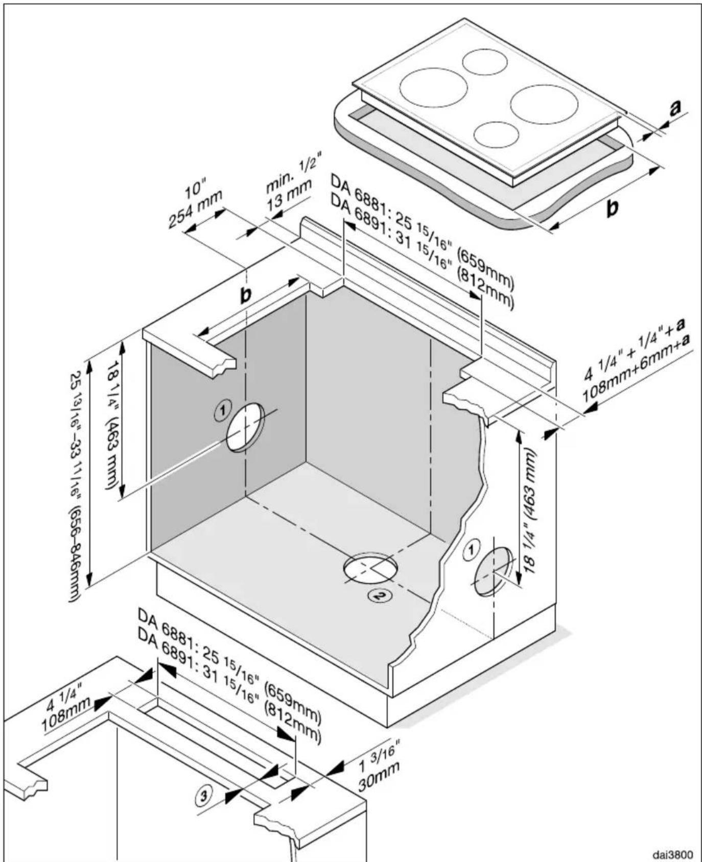
① Exhaust ducting to the right or left.
② Exhaust ducting downwards.
a) Overhang of the cooktop
b) Cooktop cutout
③ If the downdraft and cooktop are installed in separate cutouts, ensure adequate stability of the strip in between.
If the blower is to be installed at the back of the downdraft, ensure that there is adequate space for installation.
Cutout for flush-fit installation
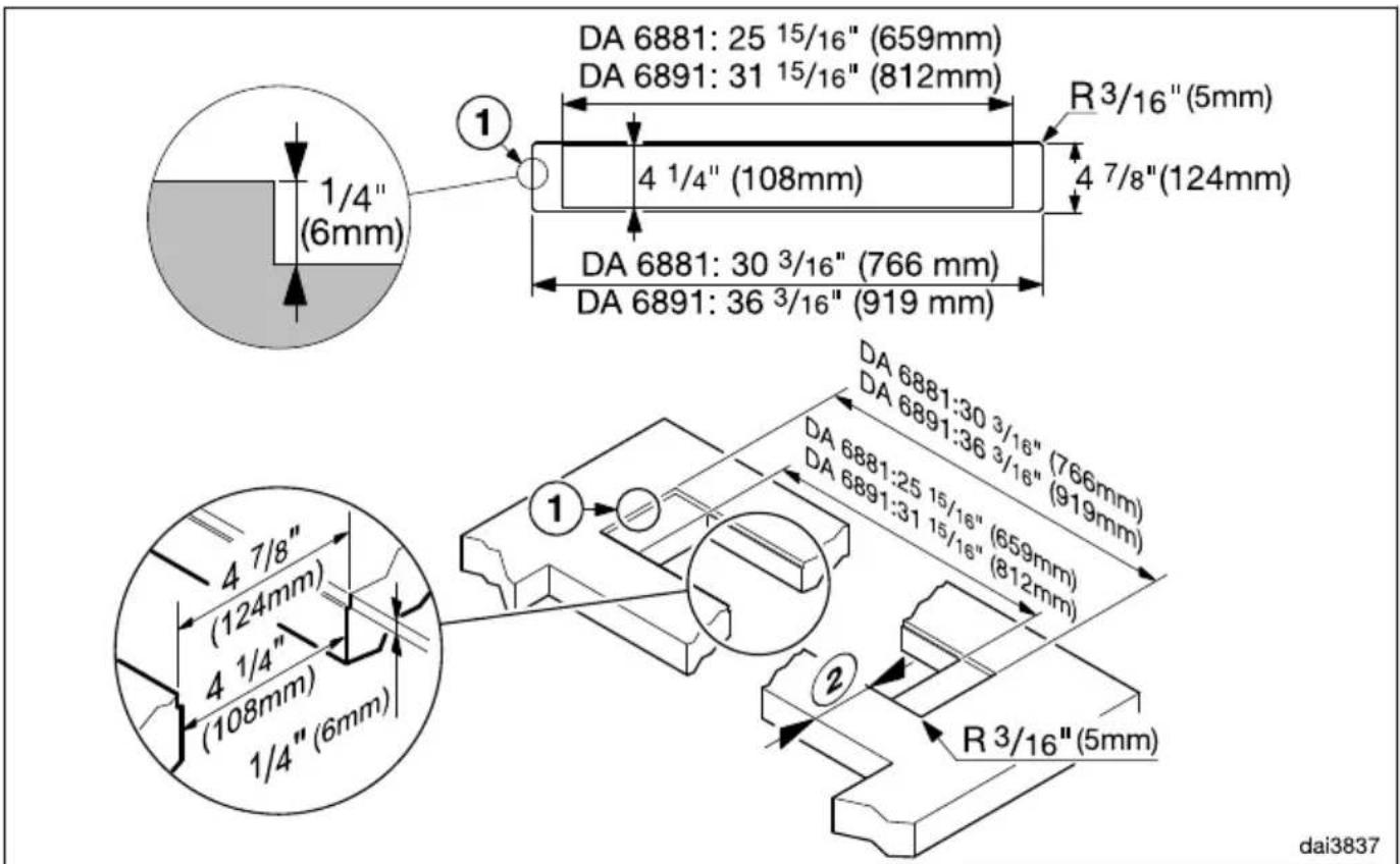
① Stepped cut-out for flush-fit installation in stone worktops (granite, marble)
② If the downdraft and cooktop are installed in separate cutouts, ensure adequate stability of the strip in between.
Support bracket
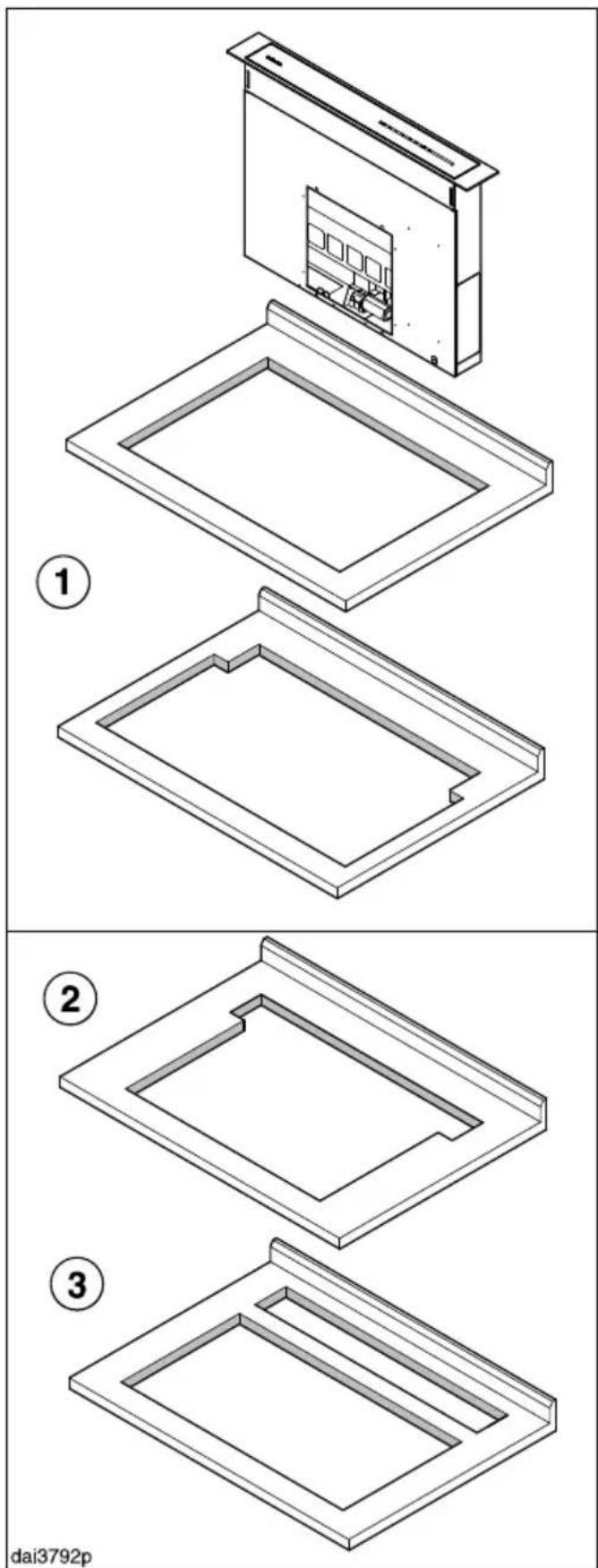
A support bracket is mounted on the downdraft. It serves as a support for the cooktop when the downdraft extractor and the cooktop are installed in a common cutout ①. In the following situations, the support bracket should be replaced with two small angle brackets:
- The downdraft and cooktop are installed in a common cutout, but the cutout for the cooktop is narrower ②
- The downdraft and cooktop are installed in two separate cutouts ③.
natural_image
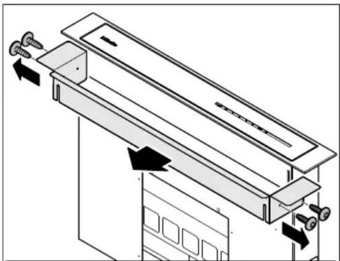
Technical diagram of a mechanical device with arrows indicating motion or force direction (no text or symbols present)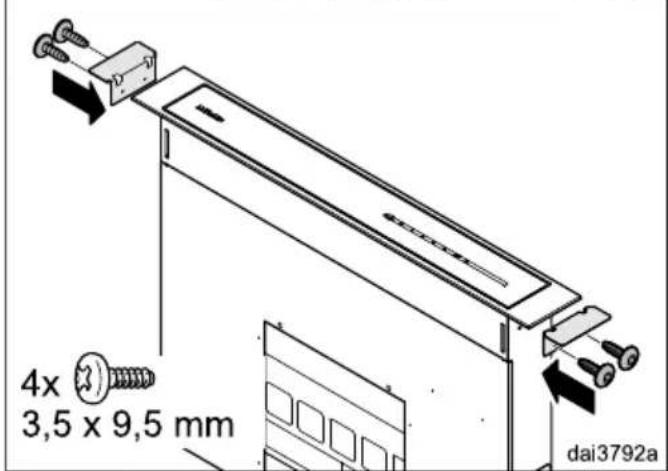
■ Unscrew the screws on either side, remove the support bracket and replace it with the two small angle brackets supplied.
natural_image
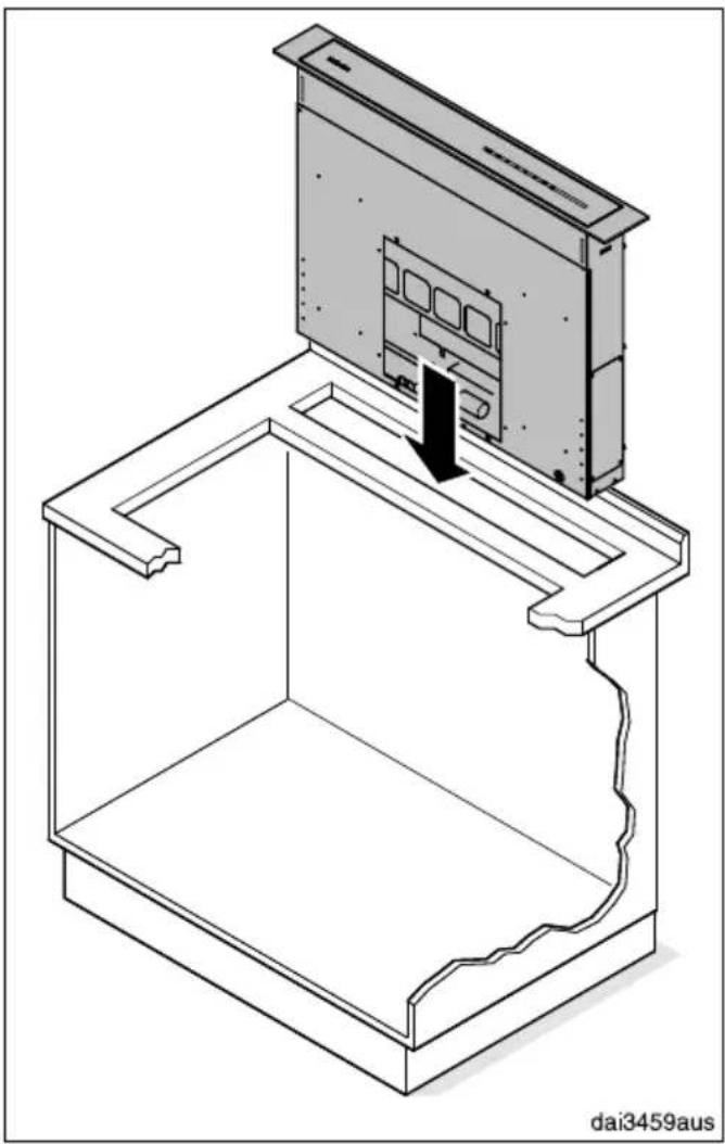
Technical line drawing of a device interior with a mounted panel and base, showing no text or symbols.■ Place the downdraft carefully into the prepared cutout (see “Appliance dimensions”).
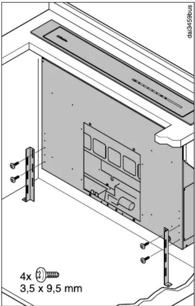
- Secure each of the lower brackets with two screws on the casing, so that the feet rest on the floor of the housing unit. To do this, you can also rotate the brackets when fitting them.
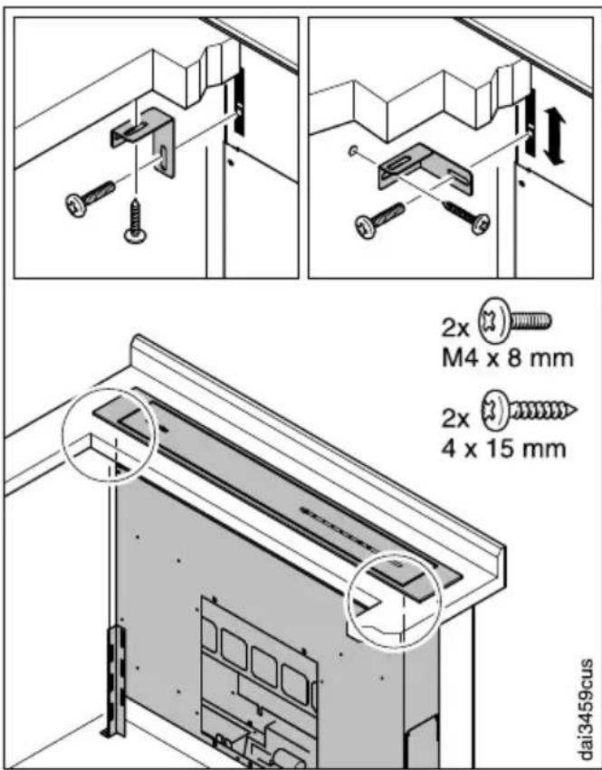
■ Fit the upper brackets loosely to the downdraft casing.
The brackets can be moved within the mounting recess.
■ Push the brackets upwards and screw them into place under the counter.
■ Tighten the screws on the casing.
■ Alternatively, the brackets can also be rotated when fitting them so that the downdraft can be secured to the sides of the housing unit.
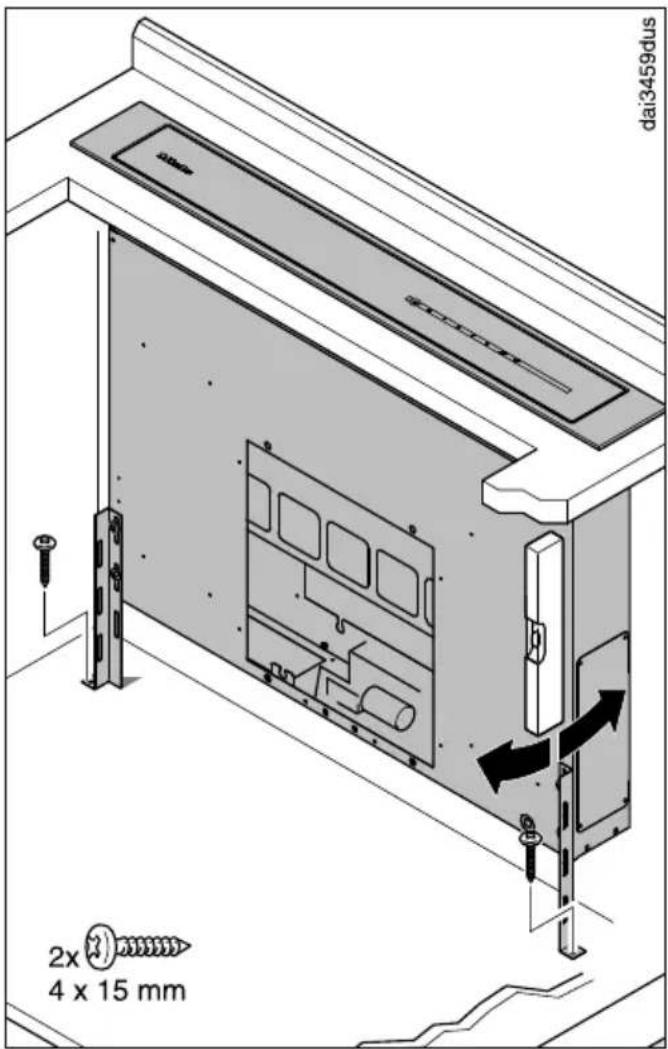
■ Align the downdraft vertically and screw the brackets securely to the base of the housing unit.
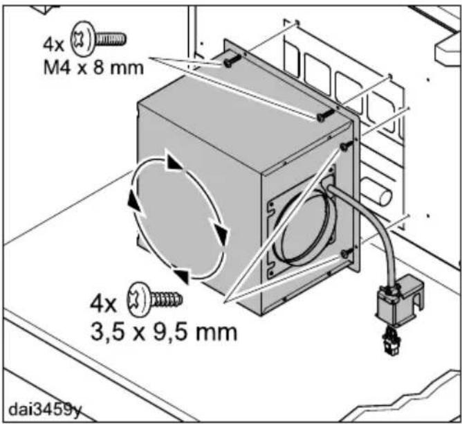
■ Rotate the motor so that the exhaust connection points in the required direction and secure it to the downdraft.
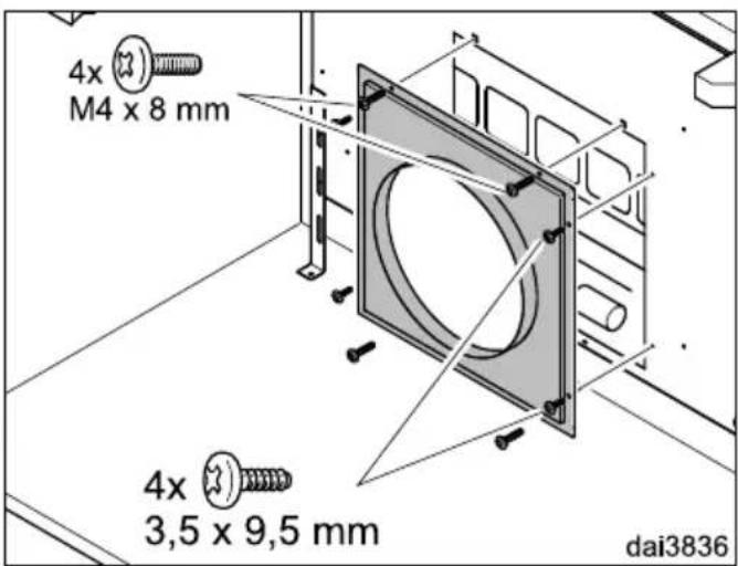
■ If an external blower is being used, the appropriate vent connector is fitted instead.
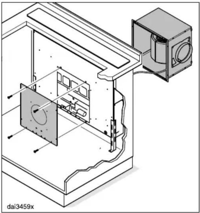
natural_image
Technical line drawing of a mechanical assembly with internal components and mounting bracket (no text or symbols)■ Alternatively, the motor can be fitted onto the downdraft from behind.
- To do this, remove the back cover from the casing and fit it onto the front.
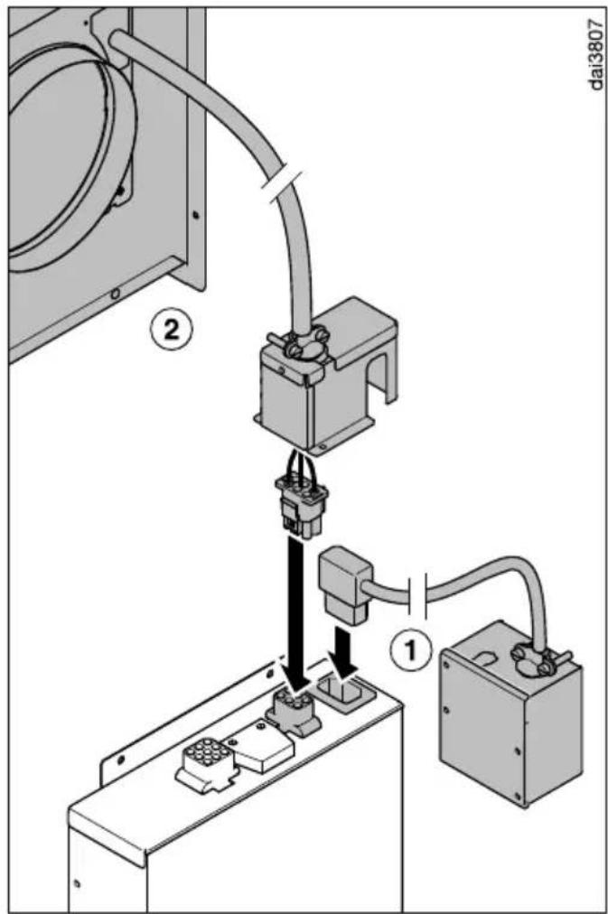
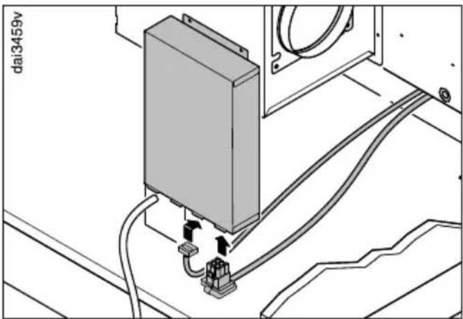
- Plug the connector from the power connection box ① into the appropriate socket on the connection box.
- Plug the connector on the connection cord from the blower unit ② into the appropriate socket on the connection box.
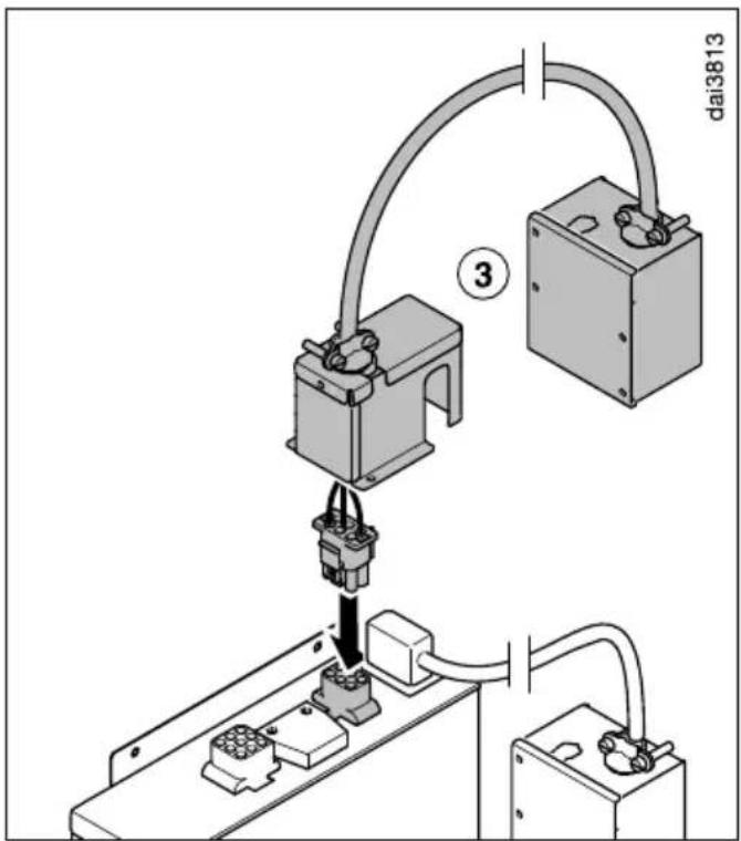
■ When using an external blower, the connection box ③ of the external blower is plugged into the appropriate socket on the connection box.
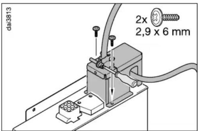
■ Loosen the screws of the cord feed-through a little.
■ Place the cover in position and secure it with the screws supplied.
■ Tighten the cord feed-through screws again.
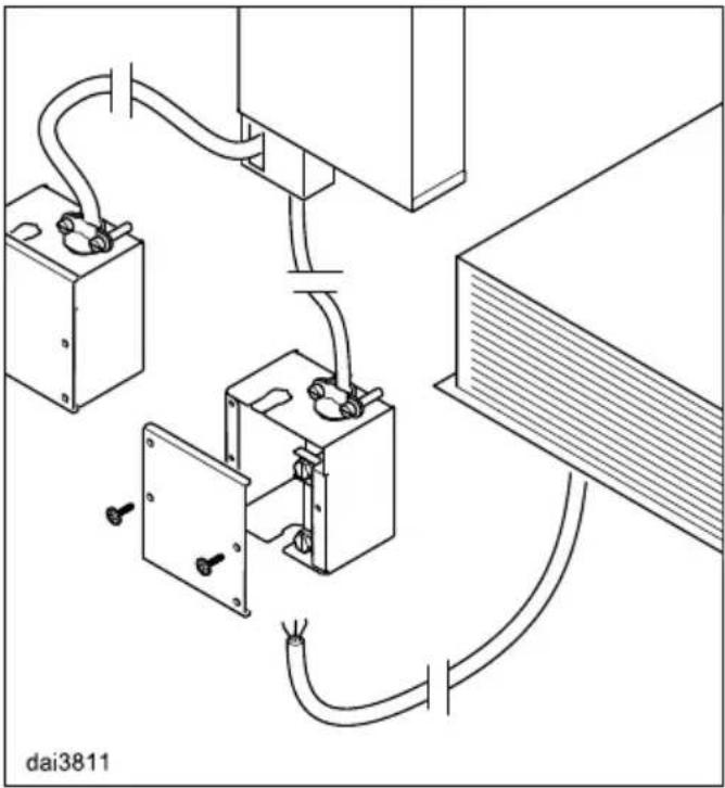
natural_image
Technical diagram of a device with wiring and connectors, no visible text or symbols■ Guide the two connection cords on the bottom of the downdraft through the casing and plug them into the appropriate sockets at the bottom of the connection box.
Make sure that the plugs click in firmly.
Close the locking catches on the middle plug.
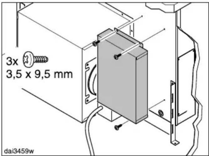
■ Fasten the connection box at a suitable location, e.g. a cabinet wall. With a DA 6891 it can be mounted on the downdraft at the indicated position to the left or right of the blower or on the back.
If moisture gets into the unit, this can cause an electric shock.
Therefore, the connection box must not be in contact with the floor.
Position and secure the cord and other connection leads in a suitable place.
natural_image
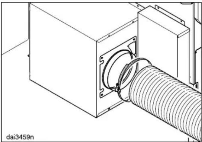
Technical line drawing of a mechanical assembly with a coiled hose and housing (no text or symbols)- Secure the exhaust ducting to the exhaust socket, e.g., with a hose clip (available as an optional accessory) on flexible ducting.
Vented mode
■ See “Connection for vented mode” for additional instructions on attaching the ducting.
Recirculation mode
If site conditions are not suitable for the downdraft extractor to be used with vented extraction, it must be set up for recirculation:
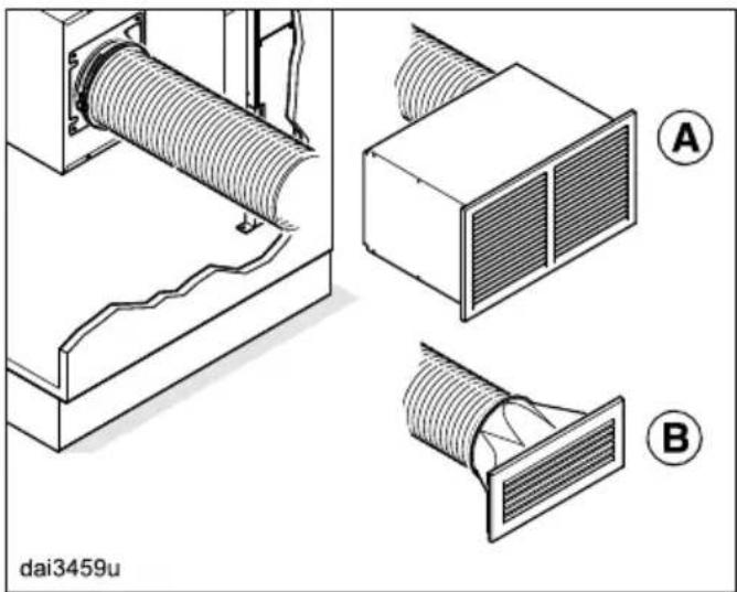
natural_image
Technical diagram showing airflow patterns around a ventilation duct, with labeled components A and B (no text or symbols beyond labels)- Connect the DUU 2900 recirculation box Ⓐ to the exhaust socket.
The charcoal filters are integrated in the recirculation box. Therefore, charcoal filters do not have to be fitted in the downdraft extractor.
or
- Alternatively for the DA 6891 only: Connect the DUU 151 recirculation conversion kit Ⓑ to the exhaust socket. The downdraft extractor grease filters must be fitted with DKF 22-1 charcoal filters (see "Cleaning and care").
Conversion kits DUU 2900 and DUU 151 are available as optional accessories.
■ See the relevant installation instructions for more information.
WARNING: Danger of toxic fumes.
Gas cooking appliances release carbon monoxide that can be harmful or fatal if inhaled.
To reduce the risk of fire and to properly exhaust air, the exhaust gases extracted by the hood should be vented outside of the building only.
Do not vent exhaust air into spaces within walls or ceilings or in attics, crawl spaces or garages.
To reduce the risk of fire, only use metal ductwork.
Please read and follow the "IMPORTANT SAFETY
INSTRUCTIONS" to reduce the risk of personal injury. Follow all local building codes when installing the hood.
The exhaust connection depends on the blower used:
DAG 600 ....∅ 6" (150 mm),
DAG 1000: ......∅ 10" (254 mm)
Only use smooth pipes or flexible duct hoses made from non-combustible materials for exhaust duct.
To achieve the greatest possible air extraction with the lowest noise levels, please observe the following:
- The cross-section of the exhaust duct must not be smaller than the cross-section of the vent collar (see appliance dimensions).
- The exhaust duct should be as short and straight as possible.
- If elbows are needed, make sure they have a large radius.
- The exhaust duct must not be kinked or compressed. When selecting the exhaust duct, ensure that it is rigid enough to retain its shape during operation.
- Make sure that all connections are secure and airtight.
Any constriction of the airflow will reduce extraction performance and increase operating noise.
doi:2538
natural_image
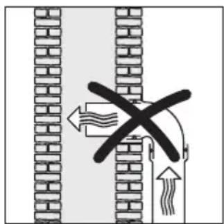
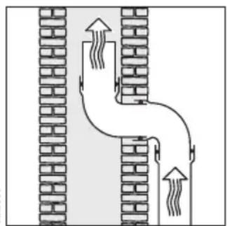
Diagram of a pipe system with two vertical brick walls and upward arrows indicating flow or movement (no text or symbols)■ If the exhaust air is to be ducted into a flue, the duct must be directed in the flow direction of the flue.
■ When duct is horizontal it must be laid to slope away at at least 18 inch per foot. This is to ensure that condensate cannot drain back into the appliance.
If the exhaust duct is to be routed through rooms, ceiling space etc., the temperatures in these different areas may differ greatly, which means that the problem of condensation will need to be addressed. The exhaust duct will need to be insulated.
Reducing Collar
(optional accessory)
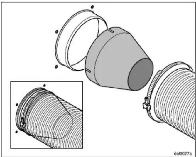
natural_image
Technical illustration of a mechanical component with a conical part inserted into it, shown in two views (top and side), no text or symbols present.If you would like to reduce the environmental impact of your ventilation system by limiting the CFM output the Reducing Collar can be installed. It reduces the air flow to less than 400 CFM. Check local building codes for max. CFM requirements.
■ Push the Reducing Collar on the exhaust port of the blower.
■ Push the exhaust hose over it.
■ Secure both with a hose clamp.
WARNING: TO REDUCE THE RISK OF FIRE, ELECTRIC SHOCK, OR INJURY TO PERSONS, OBSERVE THE FOLLOWING:
All electrical work should be performed by a qualified electrician in strict accordance with national regulations (for USA: ANSI-NFPA 70) and local safety regulations. Installation, repairs and other work by unqualified persons could be dangerous.
Ensure that power to the appliance is OFF while installation or repair work is performed.
The ventilation system may only be used with Miele DAG 600 or DAG 1000 blowers.
Verify that the voltage, load and circuit rating information found on the data plate, match the household electrical supply before installing the hood.
Use only with ventilation hood cord-connection kits that have been investigated and found acceptable for use with this model hood.
If there is any question concerning the electrical connection of this appliance to your power supply, please consult a licensed electrician or call Miele's Technical Service Department.
WARNING: THIS APPLIANCE MUST BE GROUNDED
Grounding Instructions
WARNING - Improper grounding can result in a risk of electric shock.
This appliance must be grounded. In the event of an electrical short circuit, grounding reduces the risk of electric shock by providing a path of least resistance.plug.
If there is any doubt, have the electrical system of the house checked by a qualified electrician.
To increase security before the machine is installed, it is recommended to install a protective switch (30 mA).
Power supply
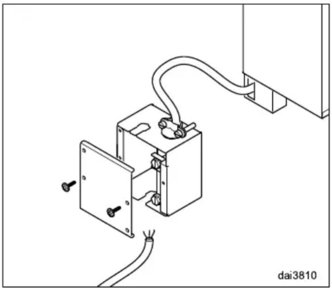
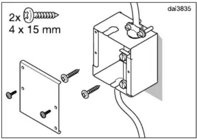
natural_image
Technical line drawing of an electrical switch assembly with wiring and mounting bracket (no text or symbols)■ Open the cover of the power connection box.
■ Remove the cover from the cord entry, e.g. with the aid of a screwdriver.
■ Install an approved cable clamp or connector.
Electrical connection
■ Guide the power cord into the connection box.
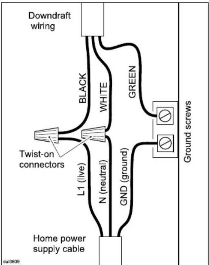
■ Connect the power cord:
Black..... L1 (live)
White ...... N (neutral)
Green/yellow ...... GND (ground)

- Secure the connection box to a suitable place, e.g. a cabinet wall.
If moisture gets into the unit, this can cause an electric shock
Therefore, the connection box must not be in contact with the floor.
Position and secure the cord and other connection leads in a suitable place.
■ Refit the cover.
Electrical connection of an external blower
Disconnect the appliance from the electrical power supply.
natural_image
Pure electrical circuit lines without any symbols■ Install a connection cord from the downdraft to the external blower. Refer to the Operating and Installation Instructions for the DAG 1000 external blower.
Use the connection box supplied with the DAG 1000 external blower for connection to the downdraft.
■ Open the cover on the connection box.
■ Remove the cover from the cord entry, e.g. with the aid of a screwdriver.
■ Install an approved cable clamp or connector.
■ Guide the connection cord from the external blower into the connection box.
■ Connect the power cord. Please check the enclosed wiring diagram.
- Secure the connection box to a suitable place, e.g. a cabinet wall.
If moisture gets into the unit, this can cause an electric shock Therefore, the connection box must not be in contact with the floor. Position and secure the cord and other connection leads in a suitable place.
■ Connect the power as described previously.
For faults that you cannot resolve on your own, please contact your Miele dealer or Miele Technical Service.
The telephone number for Miele is listed at the back of these instructions.
When contacting Miele, please state the model and serial number of your ventilation hood.
These can be found on the data plate.
Location of the data plate
The data plate is visible once you have removed the grease filters.
Warranty
For further information, please refer to your warranty booklet.
MieleCare
This service is available in USA only.
MieleCare, our Extended Service Contract program, gives you the assurance of knowing that your appliance investment is covered by 5 years of worry free ownership.
MieleCare is the only Extended Service Contract in the industry that guarantees repairs by a Miele Authorized Service Provider using genuine Miele parts. Only genuine Miele parts installed by factory trained professionals can guarantee the safety, reliability, and longevity of your Miele appliance.
Please note that unless expressly approved in writing by Miele's Service department, Extended Service Contracts offered by other providers for Miele products will not be recognized by Miele. Our goal is to prevent unauthorized (and untrained) service personnel from working on your Miele products, possibly doing further damage to them, you and/or your home.
To learn more about MieleCare
Extended Service Contracts, please contact your appliance dealer or visit us online at:
www.mieleusa.com
| Total connected load | |
| with internal DAG 600 blower 346 W | |
| with external DAG 1000 blower 216 W | |
| Supply voltage, frequency 120 V AC, 60 Hz | |
| Fuse rating 15 A | |
Please have the model and serial number of your appliance available when contacting Technical Service.
U.S.A.
Miele, Inc.
National Headquarters
9 Independence Way
Princeton, NJ 08540
Phone: 800-843-7231
Fax: 609-419-4298
www.mieleusa.com
Technical Service & Support
Phone: 800-999-1360
Fax: 888-586-8056
TechnicalService@mieleusa.com
International Headquarters
Miele & Cie. KG
Headquarters and Miele Centre
161 Four Valley Drive
Vaughan, ON L4K 4V8
www.miele.ca
Customer Care Centre
Phone: 800-565-6435
905-532-2272
customercare@miele.ca
Miele
DA 6881, DA 6891, DAG 600
- Operating and Installation Instructions Downdraft
- IMPORTANT SAFETY INSTRUCTIONS 3
- Caring for the environment 11
- Guide to the appliance.... 12
- Description of functions 14
- Operation.... 15
- Energy-saving tips.... 16
- Cleaning and care 17
- Installation.... 21
- Air venting 33
- Electrical connection 35
- Service and warranty 38
- Technical data 39
- READ AND SAVE THESE INSTRUCTIONS
- Appropriate use
- IMPORTANT SAFETY INSTRUCTIONS
- Safety with children
- Technical safety
- Correct use
- Proper installation
- Cleaning and maintenance
- Accessories
- Disposal of the packing material
- Disposal of your old appliance
- Extraction mode
- Recirculation mode
- Operation with an external blower
- Extending/retracting the canopy, switching the blower on/off
- Selecting the power level
- Reducing power of the booster level
- Selecting the delayed shutdown time
- Turning the overhead lighting on/off
- Stainless steel housing
- General information
- Special instructions for stainless steel surfaces
- Special instructions for glass surfaces
- Grease filters and edge extraction panel
- Cleaning intervals
- Removing the panel and grease filters
- Cleaning the panel
- Cleaning the grease filters by hand
- Unsuitable cleaning agents
- Cleaning the grease filters in a dishwasher
- After cleaning
- Resetting the filter saturation counter for the grease filters
- OdorFree Charcoal Filter
- How to install/replace DKF 22-1 charcoal filters
- When to change the OdorFree Charcoal Filter
- Disposing of charcoal filters
- Before installation
- Installation parts
- lower brackets
- upper brackets
- support brackets
- Cabinet dimensions
- Cutout for flush-fit installation
- Vented mode
- Reducing Collar
- Grounding Instructions
- Electrical connection
- Electrical connection of an external blower
- Location of the data plate
- Warranty
- MieleCare
- U.S.A.
- National Headquarters
- Technical Service & Support
- International Headquarters
- Headquarters and Miele Centre
- Customer Care Centre
- Miele
Brand : MIELE
Model : DAG500
Category : Range hood