
AC-82MD - Electric charger SONY - Free user manual and instructions
Find the device manual for free AC-82MD SONY in PDF.

User questions about AC-82MD SONY
0 question about this device. Answer the ones you know or ask your own.
Ask a new question about this device
Download the instructions for your Electric charger in PDF format for free! Find your manual AC-82MD - SONY and take your electronic device back in hand. On this page are published all the documents necessary for the use of your device. AC-82MD by SONY.
USER MANUAL AC-82MD SONY
The Heights, Brooklands, Weybridge
Surrey KT13 0XW, United Kingdom
Schlierer/Switzerland Branch
Wiesenstrasse 5. 8952 Schlieren, Switzerland

The Heights, Brooklands, Weybridge.
Surrey KT13 0XW, United Kingdom

Schlieren/Switzerland Branch
© 2019 Sony Corporation
| 取扱説明書 | JP |
| Instructions for Use | GB |
| Instructions d'utilisation | FR |
| Gebrauchsanweisung | DE |
| Manual de instrucciones | FS |
| Gobruiksaanwijzing | NL |
| Bruksanvisning | SE |
| Istruzioni por l'uso | IT |
| Manual de instruções | PT |
| Brugervejelching | DK |
| Käyttöohjeet | H |
| Bruksanvisning | NO |
| Instrukcja obsługi | PI |
| Oðnyieð χρήσησ | GR |
| Uživatelská přiručka | CZ |
| Használati útmutató | HU |
| Руководство по эксплуатации | RU |
| Инструкции за употреба | BG |
| Návod na obsluhu | SK |
| Navodila za uporabo | SI |
| Instrucțiuni de utilizare | RO |
| Kasutusjuhend | FF |
| Lietošanas instrukcija | LV |
| Naudojimo instrukcija | LT |
| Upute za upotrebu | HR |
| Пайдалану нускаулығы | KZ |
| 使用说明 | CS |
| 操作説明 | CT |
| 사용 설명 | KR |
| Kullanim Talimiatlan | TR |
| Uputstvo za upotrebu | SR |
| Petunjuk Penggunaan | ID |
4695566120
日本語
安全のために
natural_image
Illustration of a USB connector emitting a coin, with no text or symbols present.natural_image
Diagram of a cable connector with a pin inserted into it (no text or symbols present)Information for Customers in Europe (欧州顧客向け情報) (1)
注意
Before operating the unit, please read this manual thoroughly and retain it for future reference.
Indications for Use/Intended Use
The AC-81MD/82MD AC Adaptor is designed and intended for use with Sony's medical electrical equipment and is both a supplied accessory for some models and an optional accessory for some models. The AC-81MD/82MD Adaptor allows Sony's compatible DC-powered medical electrical equipment to operate wherever only AC power is available.
Notes
• This equipment is for medical professionals.
- This equipment is intended for use in medical environments, such as clinics, examination rooms, and operating rooms.
WARNING
To reduce the risk of fire or electric shock, do not expose this equipment to rain or moisture.
To avoid electrical shock, do not open the cabinet. Refer servicing to qualified personnel only.
No modification of this equipment is allowed.
WARNING
To avoid the risk of electric shock, this equipment must only be connected to a supply mains with protective earth.
WARNING
This unit has no power switch. To disconnect the main power, unplug the power plug. When installing the unit, incorporate a readily accessible disconnect device in the fixed wiring, or connect the power plug to an easily accessible socket-outlet near the unit. Do not position the ME equipment where it is difficult to unplug the power plug. If a fault should occur during operation of the unit, operate the disconnect device to switch the power supply off, or disconnect the power plug.
Symbols on the products

Consult the instructions for use
Follow the directions in the instructions for use for parts of the unit on which this symbol appears.

This symbol indicates the manufacturer, and appears next to the manufacturer's name and address.

This symbol indicates the Importer, and appears next to the Importer's name and registered office address.
This symbol indicates the European Community representative, and appears next to the European Community representative's name and address.
This symbol indicates the UK Responsible Person, and appears next to the UK Responsible Person's name and address.

This symbol indicates the Swiss authorized representative, and appears next to the Swiss authorized representative's name and address.
This symbol indicates the medical device in the European Community.

This symbol indicates the date of manufacture.

This symbol indicates the serial number.

Storage and transport temperature
This symbol indicates the acceptable temperature range for storage and transport environments.

Storage and transport humidity
This symbol indicates the acceptable humidity range for storage and transport environments.

Storage and transport pressure
This symbol indicates the acceptable atmospheric pressure range for storage and transport environments.
For customers in the U.S.A.
This equipment has been tested and found to comply with the limits for a Class B digital device, pursuant to part 15 of the FCC Rules. These limits are designed to provide reasonable protection against harmful interference in a residential installation. This equipment generates, uses and can radiate radio frequency energy and, if not installed and used in accordance with the instructions, may cause harmful interference to radio communications. However, there is no guarantee that interference will not occur in a particular installation. If this equipment does cause harmful interference to radio or television reception, which can be determined by turning the equipment off and on, the user is encouraged to try to correct the interference by one or more of the following measures:
- Reorient or relocate the receiving antenna.
- Increase the separation between the equipment and receiver.
- Connect the equipment into an outlet on a circuit different from that to which the receiver is connected.
- Consult the dealer or an experienced radio/TV technician for help.
You are cautioned that any changes or modifications not expressly approved in this manual could void your authority to operate this equipment.
All interface cables used to connect peripherals must be shielded in order to comply with the limits for a digital device pursuant to Subpart B of part 15 of FCC Rules.
This device complies with part 15 of the FCC Rules. Operation is subject to the following two conditions: (1) This device may not cause harmful interference, and (2) this device must accept any interference received, including interference that may cause undesired operation.
For customers in Canada
This unit has been certified according to Standard CAN/CSA-C22.2 No.60601-1.
AC-81MD only
For customers in the U.S.A. and Canada
Model AC-81MD is non-patient equipment. The unit cannot be used in the vicinity of patients.
Patient vicinity
Important safeguards and notices for use in the medical environments
- All devices connected to the unit must be certified or compliant according to IEC 60601-1, IEC 60950-1, and
IEC 60065 standards and other IEC/ISO standards applicable to the devices.
-
Furthermore, the system as a whole must comply with IEC 60601-1 standards. All peripheral devices connected to the signal input/output sections of the unit constitute the medical-use system, and therefore, the user is responsible for ensuring that the system as a whole complies with IEC 60601-1 standards. If in doubt, consult qualified Sony service personnel.
-
Do not come into contact with patients while you are in contact with the unit.
The unit cannot be used in the patient environment.
* Patient Environment
-
Connecting the unit to other devices may increase the leakage current.
-
For all peripheral devices connected to the unit that operate on commercial power supplies and do not comply with IEC 60601-1 standards, incorporate an isolation transformer that complies with IEC 60601-1 standards and connect to the commercial power supply via the transformer.
-
The unit generates, uses, and may radiate radio frequency energy. If it is not installed and used in accordance with the instruction manual, it may cause interference on other devices. If the unit causes interference (which can be determined by disconnecting the
power cord from the unit), try the following.
- Relocate the unit with respect to the affected devices.
- Connect the unit and the affected devices to different branch circuits.
For more information, consult qualified Sony service personnel.
(Applicable standard: IEC 60601-1-2)
Note
The accessibility of the plug part of the DC OUT connector of this AC adaptor is taken into account in the description of the patient environment. This adaptor can be used in the patient environment because the plug part of the DC OUT connector does not come in contact with human body while this adaptor is connected with Sony medical printers, recorders, etc.
AC-82MD only
Important safeguards and notices for use in the medical environments
-
All devices connected to the unit must be certified or compliant according to IEC 60601-1, IEC 60950-1, and IEC 60065 standards and other IEC/ISO standards applicable to the devices.
-
Furthermore, the system as a whole must comply with IEC 60601-1 standards. All peripheral devices connected to the signal input/output sections of the unit constitute the medical-use system, and therefore, the user is responsible for ensuring that the system as a whole complies with IEC 60601-1 standards. If in doubt, consult qualified Sony service personnel.
-
Connecting the unit to other devices may increase the leakage current.
-
For all peripheral devices connected to the unit that operate on commercial power supplies and do not comply with IEC 60601-1 standards, incorporate an isolation transformer that complies with IEC 60601-1 standards and connect to
the commercial power supply via the transformer.
- The unit generates, uses, and may radiate radio frequency energy. If it is not installed and used in accordance with the instruction manual, it may cause interference on other devices. If the unit causes interference (which can be determined by disconnecting the power cord from the unit), try the following.
– Relocate the unit with respect to the affected devices.
- Connect the unit and the affected devices to different branch circuits.
For more information, consult qualified Sony service personnel.
(Applicable standard: IEC 60601-1-2)
Important EMC notices for use in medical environments
- The AC-81MD/82MD needs special precautions regarding EMC and needs to be installed and put into service according to the EMC information provided in the instructions for use.
- The AC-81MD/82MD is intended for use in a professional healthcare facility environment.
- Portable and mobile RF communications equipment, such as cellular phones, can affect the AC-81MD/82MD.
Warning
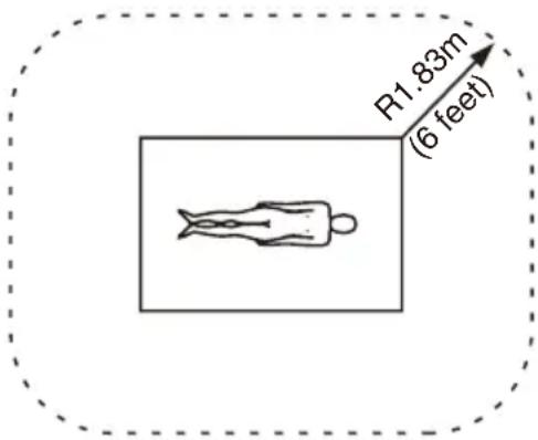
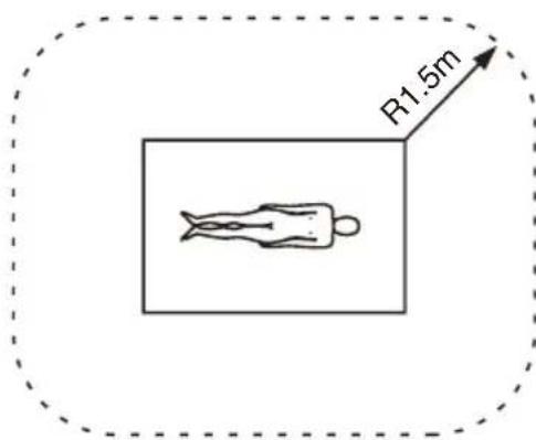
- Portable RF communications equipment should be used no closer than 30 cm (12 inches) to any part of the AC-81MD/82MD. Otherwise, degradation of the performance of this equipment could result.
- If the AC-81MD/82MD will be used adjacent to or stacked with other equipment, normal operation of the AC-81MD/82MD under such configurations should be verified via observation.
- The use of accessories and cables other than those specified, with the exception of replacement parts sold by Sony Corporation, may result in increased emissions or decreased immunity of the AC-81MD/82MD.
| Guidance and manufacturer's declaration – electromagnetic emissions | ||
| The AC-81MD/82MD is intended for use in the electromagnetic environment specified below. The customer or the user of the AC-81MD/82MD should assure that it is used in such an environment. | ||
| Emission test Compliance Electromagnetic Environment – guidance | ||
| RF emissionsCISPR 11 Group 1 | The AC-81MD/82MD uses RF energy only for its internal function. Therefore, its RF emissions are very low and are not likely to cause any interference in nearby electronic equipment. | |
| RF emissionsCISPR 11CISPR 32 | Class B | The AC-81MD/82MD is suitable for use in all establishments, including domestic establishments and those directly connected to the public low-voltage power supply network that supplies buildings used for domestic purposes. |
| Harmonic emissionsIEC 61000-3-2 | Class A | |
| Voltage fluctuations/flicker emissionsIEC 61000-3-3 | Complies | |
| Guidance and manufacturer's declaration - electromagnetic immunity | |||||
| The AC-81MD/82MD is intended for use in the electromagnetic environment specified below. The customer or the user of the AC-81MD/82MD should assure that it is used in such an environment. | |||||
| Immunity test | IEC 60601 test level | Compliance level | Electromagnetic environment - guidance | ||
| Electrostatic discharge (ESD) | ±8 kV contact ±15 kV air ±15 | 8 kV contact Floors | should be wood, concrete or ceramic tile. If floors are covered with synthetic material, a relative humidity of at least 30% is recommended. | ||
| IEC 61000-4-2 | kV air | ||||
| Electrical fast transient/burst | ±2 kV for power supply lines | ±2 kV for power supply lines | Mains power quality should be that of a typical commercial or hospital environment. | ||
| IEC 61000-4-4 | ±1 kV for input/output lines | ±1 kV for input/output lines | |||
| Surge ±1 kV line(s) to line(s) | ±2 kV line(s) to earth | ±1 kV differential mode | Mains power quality should be that of a typical commercial or hospital environment. | ||
| IEC 61000-4-5 | ±2 kV common mode | ||||
| Voltage dips, short interruptions and voltage variations on power supply input linesIEC 61000-4-11 | 0% U_T (100% dip in U_T )for 0.5/1 cyclesa40% U_T (60% dip in U_T )for 5 cycles70% U_T (30% dip in U_T )for 25/30 cyclesa(for 0.5 sec)0% U_T (100% dip in U_T )for 250/300 cyclesa(for 5 sec) | 0% U_T (100% dip in U_T )for 0.5/1 cyclesa40% U_T (60% dip in U_T )for 5 cycles70% U_T (30% dip in U_T )for 25/30 cyclesa(for 0.5 sec)0% U_T (100% dip in U_T )for 250/300 cyclesa(for 5 sec) | Mains power quality should be that of a typical commercial or hospital environment. If the user of the AC-81MD/82MD requires continued operation during power mains interruptions, it is recommended that the AC-81MD/82MD be powered from an uninterruptible power supply or a battery. | ||
| Power frequency(50/60 Hz)magnetic fieldIEC 61000-4-8 | 30 A/m 30 A/m | Power frequency | magnetic fields should be at levels characteristic of a typical location in a typical commercial or hospital environment. | ||
| NOTE: U_T is the a.c. mains voltage prior to application of the test level. | |||||
| a For example, 10/12 means 10 cycles at 50 Hz or 12 cycles at 60 Hz. | |||||
| Guidance and manufacturer's declaration - electromagnetic immunity | |||||
| The AC-81MD/82MD is intended for use in the electromagnetic environment specified below. The customer or the user of the AC-81MD/82MD should assure that it is used in such an environment. | |||||
| Immunity test | IEC 60601 test level | Compliance level | Electromagnetic environment - guidance | ||
| Conducted RF IEC 61000-4-6 | 3 Vrms 150 kHz to 80 MHz outside ISM bandsc | 3 Vrms d = 1.2 | Portable and mobile RF communications equipment should be used no closer to any part of the AC-81MD/82MD, including cables, than the recommended separation distance calculated from the equation appliance to the frequency of the transmitter.Recommended separation distance | ||
| 6 Vrms 150 kHz to 80 MHz in ISM bandsc | 6 Vrms | ||||
| Radiated RF 3 IEC 61000-4-3 | V/m 3 V/m IEC 60601-1-2: 2007 | d = 1.2 √P 80 MHz to 800 MHzd = 2.3 √P 800 MHz to 2.5 GHzIEC 60601-1-2: 2014d = 2.0 √P 80 MHz to 2.7 GHzWhere P is the maximum output power rating of the transmitter in watts (W) according to the transmitter manufacturer and d is the recommended separation distance in meters (m).Field strengths from fixed RF transmitters, as determined by an electromagnetic site survey, a should be less than the compliance level in each frequency range. b | |||
80 MHz to 2.7 GHzInterference may occur in the vicinity of equipment marked with following symbol:  | |||||
| NOTE 1: At 80 MHz and 800 MHz, the higher frequency range applies. | |||||
| NOTE 2: These guidelines may not apply in all situations. Electromagnetic propagation is affected by absorption and reflection from structures, objects and people. | |||||
| a Field strengths from fixed transmitters, such as base stations for radio (cellular/cordless) telephones and land mobile radios, amateur radio, AM and FM radio broadcast and TV broadcast cannot be predicted theoretically with accuracy. To assess the electromagnetic environment due to fixed RF transmitters, an electromagnetic site survey should be considered. If the measured field strength in the location in which the AC-81MD/82MD is used exceeds the applicable RF compliance level above, the AC-81MD/82MD should be observed to verify normal operation. If abnormal performance is observed, additional measures may be necessary, such as reorienting or relocating the AC-81MD/82MD. | |||||
| b Over the frequency range 150 kHz to 80 MHz, field strengths should be less than 3 V/m. | |||||
| c The ISM (industrial, scientific and medical) bands between 150 kHz and 80 MHz are 6.765 MHz to 6.795 MHz; 13.553 MHz to 13.567 MHz; 26.957 MHz to 27.283 MHz; and 40.66 MHz to 40.70 MHz. | |||||
| Recommended separation distances between portable and mobile RF communications equipment and the AC-81MD/82MD | |||||
| The AC-81MD/82MD is intended for use in an electromagnetic environment in which radiated RF disturbances are controlled. The customer or the user of the AC-81MD/82MD can help prevent electromagnetic interference by maintaining a minimum distance between portable and mobile RF communications equipment (transmitters) and the AC-81MD/82MD as recommended below, according to the maximum output power of the communications equipment. | |||||
| Rated maximum output power of transmitter W | Separation distance according to frequency of transmitter m | ||||
| IEC 60601-1-2 : 2007 IEC 60601-1 -2 : 2014 | |||||
| 150 kHz to 80 MHz d = 1.2 | 80 MHz to 800 MHz d = 1.2 | 800 MHz to 2.5 GHz d = 2.3 | 150 kHz to 80 MHz d = 1.2 | 80 MHz to 2.7 GHz d = 2.0 | |
| 0.01 0.12 0.1 | 2 0.23 0.12 0.20 | ||||
| 0.1 0.38 0.38 | 8 0.73 0.38 0.63 | ||||
| 1 1.2 1.2 2.3 | 3 1.2 2.0 | ||||
| 10 3.8 3.8 7.3 | 3 3.8 6.3 | ||||
| 1 | 0 | 0 | 1 | 2 | 1 |
| For transmitters rated a maximum output power not listed above, the recommended separation distance d in meters (m) can be estimated using the equation applicable to the frequency of the transmitter, where P is the maximum output power rating of the transmitter in watts (W) according to the transmitter manufacturer.NOTE 1: At 80 MHz and 800 MHz, the separation distance for the higher frequency range applies.NOTE 2: These guidelines may not apply in all situations. Electromagnetic propagation is affected by absorption and reflection from structures, objects and people.Guidance and manufacturer's declaration – electromagnetic immunity | |||||
| The AC-81MD/82MD is intended for use in an electromagnetic environment in which radiated RF disturbances are controlled. Portable RF communications equipment should be used no closer than 30 cm (12 inches) to any part of the AC-81MD/82MD. Otherwise, degradation of the performance of this equipment could result. | |||||
| Immunity test | Band^a | Service^a | Modulation | IEC 60601 test level | Compliance level |
| Proximity fields from RF wireless communications equipmentIEC 61000-4-3 | 380 - 390 MHz | TETRA 400 | Pulse modulation 18 Hz | 27 V/m 27 | V/m |
| 430 - 470 MHz | GMRS 460 FRS 460 | FM ±5 kHz deviation 1 kHz sine | 28 V/m 28 | V/m | |
| 704 - 787 MHz | LTE Band 13, 17 | Pulse modulation 217 Hz | 9 V/m 9 V/m | ||
| 800 - 960 MHz | GSM 800/900 TETRA 800 iDEN 820 CDMA 850 LTE Band 5 | Pulse modulation 18 Hz | 28 V/m 28 | V/m | |
| 1,700 - 1,990 MHz | GSM 1800 CDMA 1900 GSM 1900 DECT LTE Band 1, 3, 4, 25 UMTS | Pulse modulation 217 Hz | 28 V/m 28 | V/m | |
| 2,400 - 2,570 MHz | Bluetooth WLAN 802.11 b/g/n RFID 2450 LTE Band 7 | Pulse modulation 217 Hz | 28 V/m 28 | V/m | |
| 5,100 - 5,800 MHz | WLAN 802.11 a/n | Pulse modulation 217 Hz | 9 V/m 9 V/m | ||
| NOTE: These guidelines may not apply in all situations. Electromagnetic propagation is affected by absorption and reflection from structures, objects and people. | |||||
| a For some services, only the uplink frequencies are included. | |||||
Caution
When you dispose of the unit or accessories, you must obey the laws in the relative area or country and the regulations in the relative hospital regarding environmental pollution.

Warning on power connections
Use a proper power cord for your local power supply.
-
Use the approved Power Cord (3-core mains lead) / Appliance Connector / Plug with earthing-contacts that conforms to the safety regulations of each country if applicable.
-
Use the Power Cord (3-core mains lead) / Appliance Connector / Plug conforming to the proper ratings (Voltage, Ampere).
If you have questions on the use of the above Power Cord / Appliance Connector / Plug, please consult a qualified service personnel.

Warning on power connections for medical use
Customers in the U.S.A. and Canada should use the following type of power cord. Customers in other countries or regions should use the power cord prescribed by their country or region.
| U.S.A. and Canada | |
| Plug type HOSPITAL | GRADE* |
| Cord type Min. Type | SJTMin. 18 AWG |
| Minimum rating for plug and appliance couplers | 10 A / 125 V |
| Safety approval UL | Listed and CSA |
* Note: Grounding reliability can only be achieved when the equipment is connected to an equivalent receptacle marked “Hospital Only” or “Hospital Grade”.
WARNING
The apparatus shall not be exposed to dripping or splashing. No objects filled with liquids, such as vases, shall be placed on the apparatus.
IMPORTANT
The nameplate is located on the bottom.
Caution
Do not install the appliance in a confined space, such as book case or built-in cabinet.

Caution
Do not use the device in a MR (Magnetic Resonance) environment.
It may cause a malfunction, fire, and unwanted movement.
For the customers in the U.S.A.
SONY LIMITED WARRANTY - Please
visit http://www.sony.com/psa/warranty for important information and complete terms and conditions of Sony's limited warranty applicable to this product.
For the customers in Canada
SONY LIMITED WARRANTY - Please visit http://www.sonybiz.ca/pro/lang/en/ca/article/resources-warranty for important information and complete terms and conditions of Sony's limited warranty applicable to this product.
For the customers in Europe
Sony Professional Solutions Europe - Standard Warranty and Exceptions on Standard Warranty. Please visit https://pro.sony/support-services/primesupport/support-professional-solutions-europe-standard-product-warranty for important information and complete terms and conditions.
For the customers in Korea
SONY LIMITED WARRANTY - Please visit http://bpeng.sony.co.kr/handler/BPAS-Start for important information and complete terms and conditions of Sony's limited warranty applicable to this product.
Overview
This AC adaptor is designed exclusively for use with Sony medical equipment.
This adaptor transforms AC power supplies using an isolated transformer, and converts them into DC power supplies via rectifying and smoothing.
For details on connecting and using this unit, refer to the manual for your equipment.
Location and Function of Parts and Controls
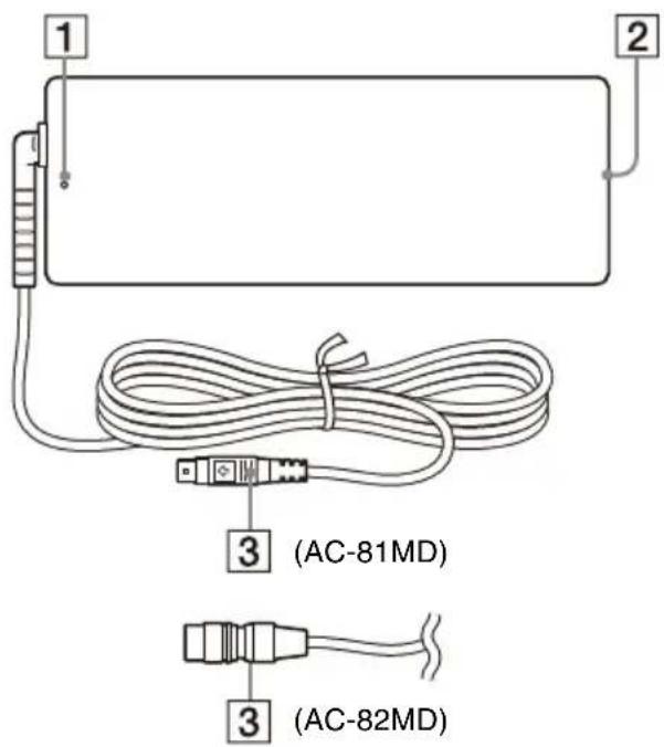
1 LED lamp
Lights when the power is on.
② AC IN connector
Connect the AC power cord.
③ DC OUT connector
Connect the DC cable to the DC IN connector of the medical equipment.

Caution
Connect the DC OUT connector to the equipment, and then connect the AC power cord of the AC adaptor.
When disconnecting the DC OUT connector, disconnect the AC power cord of the AC adaptor before disconnecting the DC OUT connector.
AC-81MD only
Do not touch the patient and the pin of the DC OUT connector at the same time. The pin of the DC OUT connector applies a voltage of 24 V, which may harm the patient.
How to Connect the DC Cable
For the AC-81MD
Note
Before connecting or disconnecting the DC cable, be sure to unplug the power plug from the mains outlet.
Insert the DC cable into the DC IN connector of the medical equipment with its arrow mark facing upwards.
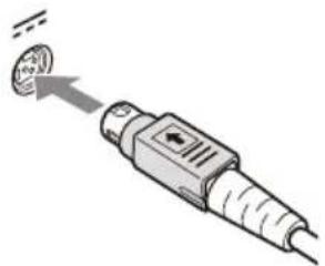
natural_image
Illustration of a USB connector emitting a circular component (no text or symbols)Make sure that the DC cable is connected securely until it is locked.
Disconnecting the DC Cable
Hold the DC OUT connector to pull the DC cable out.
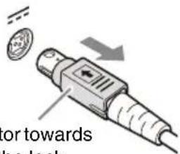
Pull the connector towards you to release the lock.
For the AC-82MD
Note
Before connecting or disconnecting the DC cable, be sure to unplug the power plug from the mains outlet.
Align the pin positions of the DC cable and the DC IN connector on the medical equipment, and insert the cable.
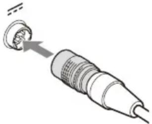
natural_image
Diagram of a medical or surgical device with a pointed tip inserted into a threaded connector (no text or symbols)Make sure that the DC cable is connected securely until it is locked.
Disconnecting the DC Cable
Hold the DC OUT connector to pull the DC cable out.
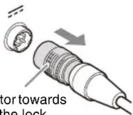
Pull the connector towards you to release the lock.
Usage Notes
Condensation
If the unit is suddenly taken from a cold to a warm location, or if ambient temperature suddenly rises, moisture may form on the outer surface of the unit and/or inside of the unit. This is known as condensation. If condensation occurs, turn off the unit and wait until the condensation clears before operating the unit. Operating the unit while condensation is present may damage the unit.
Consumable parts
The life expectancy of the AC adapter and the electrolytic capacitor is about 5 years under normal operating temperatures and normal usage (8 hours per day; 25 days per month). If usage exceeds the above normal usage frequency, the life expectancy may be reduced correspondingly.
Maintenance
Using benzene, thinners, acidic cleaning solutions, alkaline cleaning solutions, solutions containing polishing agents, chemical cloths, and other volatile solvents may damage the surface finish of the unit. Obey the following when cleaning the unit.
- Wipe the unit's surface using isopropyl alcohol with a concentration of 50% to 70% v/v or ethanol with a concentration of 76.9% to 81.4% v/v.
- For stubborn dirt, lightly moisten a soft cloth with a mild detergent that has been diluted with water, use the cloth to remove the dirt, and then wipe again using the previous concentration of solution and a new cloth.
Do not wipe with excessive pressure when using a cloth on which dirt and other particles are attached, as doing so may scratch the unit's surface.
Specifications
Power Requirements
100 V - 240 V AC, 50/60 Hz
Input Current 1.0 A - 0.5 A
Output voltage
24 V DC
Output current
3.3 A Max.
Operating Temperature
0^ to 40^ (32°F to 104°F)
Operating Humidity
20% to 85% (no condensation allowed)
Operating Pressure
700 hPa to 1,060 hPa
Storage and Transport Temperature
-20^ to +60^ ( -4^ to +140^ )
Storage and Transport Humidity
20% to 90% (no condensation allowed)
Storage and Transport Pressure
700 hPa to 1,060 hPa
Dimensions 60 × 35 × 160 mm (w/h/d)
(2 3/8 × 1 7/16 × 6 3/8 inches) Not incl. projecting parts
Mass AC-81MD: 400 g (14 oz.) (AC
adaptor only)
AC-82MD: 410 g (14 oz.) (AC adaptor only)
Accessories provided
Instructions for Use (1)
Service Contact List (1)
Information for Customers in Europe (1)
The design and these specifications are subject to change without prior notification.
Medical Specifications
Protection against electric shock: Class I
Protection against harmful ingress of water: Ordinary
Degree of safety in the presence of a flammable anesthetic mixture with air or with oxygen or nitrous oxide:
Not suitable for use in the presence of a flammable anesthetic mixture with air or with oxygen or nitrous oxide
Mode of operation: Continuous
Notes
• Always verify that the unit is operating properly before use. SONY WILL NOT BE LIABLE FOR DAMAGES OF ANY KIND INCLUDING, BUT NOT LIMITED TO, COMPENSATION OR REIMBURSEMENT ON ACCOUNT OF THE LOSS OF PRESENT OR PROSPECTIVE PROFITS DUE TO FAILURE OF THIS UNIT, EITHER DURING THE WARRANTY PERIOD OR AFTER EXPIRATION OF THE WARRANTY, OR FOR ANY OTHER REASON WHATSOEVER.
• SONY WILL NOT BE LIABLE FOR CLAIMS OF ANY KIND MADE BY USERS OF THIS UNIT OR MADE BY THIRD PARTIES.
- SONY WILL NOT BE LIABLE FOR THE TERMINATION OR DISCONTINUATION OF ANY SERVICES RELATED TO THIS UNIT THAT MAY RESULT DUE TO CIRCUMSTANCES OF ANY KIND.
Français
natural_image
Illustration of a cable connector with a magnified view showing a small component (no text or symbols)natural_image
Diagram of a connector with a cable and plug, showing a pin inserted into a socket (no text or symbols present)natural_image
Illustration of a USB connector emitting a small metallic component (no text or symbols)natural_image
Diagram of a connector with a screw and cable, showing a pin inserted into a socket (no text or symbols present)Information for Customers in
natural_image
Illustration of a USB connector with a cable and a small circular component inserted (no text or symbols)natural_image
Diagram of a mechanical component with a pin inserted into a housing (no text or symbols)Information for Customers in
(Toepasseljke norm: IEC 60601-1-2)
Opmerking
(Toepasseljke norm: IEC 60601-1-2)
natural_image
Illustration of a USB connector emitting a small metallic component (no text or symbols)natural_image
Diagram of a connector with a cable and a metallic tip, showing internal structure (no text or symbols)Information for Customers in
natural_image
Illustration of a USB connector emitting a circular component (no text or symbols)natural_image
Diagram of a connector with a screw and cable, showing a pin inserted into a socket (no text or symbols present)(Standard applicabile: IEC 60601-1-2)
Nota
(Standard applicabile: IEC 60601-1-2)
natural_image
Illustration of a USB connector with a close-up of its tip (no text or symbols)natural_image
Diagram of a connector with a cable and plug, showing a pin inserted into a socket (no text or symbols present)Information for Customers in
natural_image
Illustration of a USB connector with a close-up of its tip (no text or symbols)natural_image
Diagram of a connector with a cable and a metallic tip, showing internal structure (no text or symbols)Information for Customers in
natural_image
Illustration of a plug with a connector emitting a circular component (no text or symbols)natural_image
Diagram of a connector with a cable and a metallic tip, showing internal structure (no text or symbols)Kontroller, at DC-kablet er sikkert tilsluttet, indtil det låses.
natural_image
Illustration of a USB cable with a connector emitting a power plug (no text or symbols)natural_image
Diagram of a connector with a cable and plug, showing a close-up of the cable (no text or symbols present)Information for Customers in
Europe (Tietoa asiakkaille
Euroopassa) (1)
(Gjeldende standard: IEC 60601-1-2)
Merk
(Magnetic Resonance)-utstyr.
Det kan forårsake en feil, brann eller uønsket bevegelse.
Oversikt
natural_image
Illustration of a USB connector emitting a small circular component (no text or symbols)natural_image
Diagram of a mechanical component with a pin inserted into a housing (no text or symbols)Information for Customers in
natural_image
Illustration of a USB connector emitting a small circular component (no text or symbols)natural_image
Diagram of a connector with a screw and cable, showing a pin inserted into a socket (no text or symbols present)Information for Customers in
natural_image
Illustration of a plug with a bulb emitting a small circular component (no text or symbols)natural_image
Diagram of a connector with a cable and plug, showing a close-up of the cable (no text or symbols present)Information for Customers in
natural_image
Illustration of a plug with a circular connector emitting a droplet (no text or symbols)natural_image
Diagram of a connector with a screw and cable, showing a pin inserted into a socket (no text or symbols present)natural_image
Illustration of a USB connector emitting a small circular component (no text or symbols)natural_image
Diagram of a connector with a screw and cable, showing a pin inserted into a socket (no text or symbols present)natural_image
Illustration of a plug with a screw tip emitting powder (no text or symbols)natural_image
Diagram of a connector with a screw and cable, showing a pin inserted into a socket (no text or symbols present)natural_image
Illustration of a USB connector emitting a coin, with no text or symbols present.natural_image
Diagram of a connector with a screw and cable, showing a pin inserted into a socket (no text or symbols present)natural_image
Diagram of a mechanical component with a cylindrical part and an arrow indicating direction (no text or symbols)natural_image
Illustration of a USB connector with a cable and a small circular component inserted (no text or symbols)natural_image
Diagram of a mechanical component with a pointed tip and threaded end, showing internal structure (no text or symbols)(Veljaven standard: IEC 60601-1-2)
Opomba
(Veljaven standard: IEC 60601-1-2)
natural_image
Illustration of a USB connector emitting a metallic coin (no text or symbols)Preverite, ali je kabel za enosmerni tok dovolj priključen in zataknjen.
natural_image
Diagram of a connector with a cable and plug, showing a close-up of the cable (no text or symbols present)Preverite, ali je kabel za enosmerni tok dovolj priključen in zataknjen.
Information for Customers in
natural_image
Illustration of a plug with a connector emitting a circular component (no text or symbols)natural_image
Diagram of a connector with a screw and cable, showing a pin inserted into a socket (no text or symbols present)natural_image
Diagram of a medical or laboratory device with a magnified inset showing internal components (no text or symbols)natural_image
Illustration of a USB connector emitting a small circular component (no text or symbols)natural_image
Illustration of a handheld electronic device emitting coins with an arrow indicating direction (no text or symbols)natural_image
Diagram of a connector with a cable and plug, showing a pin inserted into a socket (no text or symbols present)Kaal AC-81MD: 400 g (ainult
Information for Customers in
Europe (Teave klientidele
Euroopas) (1)
natural_image
Illustration of a USB cable connector emitting a small circular component (no text or symbols)natural_image
Diagram of a connector with a screw and cable, showing a pin inserted into a socket (no text or symbols present)Information for Customers in
natural_image
Illustration of a plug with a connector emitting a circular component (no text or symbols)natural_image
Diagram of a connector with a screw and cable, showing a pin inserted into a socket (no text or symbols present)Information for Customers in
Europe (Informacija Europos
klientams) (1)
natural_image
Illustration of a USB connector emitting a metallic coin (no text or symbols)natural_image
Diagram of a connector with a screw and cable, showing a pin inserted into a socket (no text or symbols present)natural_image
Illustration of a USB connector emitting a small circular component (no text or symbols)natural_image
Diagram of a connector with a cable and plug, showing a pin inserted into a socket (no text or symbols present)natural_image
Illustration of a USB connector emitting a circular component (no text or symbols)确保直流电缆牢固连接直至锁定。
断开直流电缆
natural_image
Diagram of a connector with a screw and cable, showing a pin inserted into a socket (no text or symbols present)确保直流电缆牢固连接直至锁定。
断开直流电缆
natural_image
Illustration of a USB connector emitting a small circular component (no text or symbols)確定直流纜線牢牢連接並鎖定。
拔掉直流纜線
natural_image
Diagram of a medical or laboratory device with a pointed tip inserted into a cylindrical component (no text or symbols)確定直流纜線牢牢連接並鎖定。
拔掉直流纜線
$$ \text {維修聯絡清單} (1) $$
$$ \text { Information for Customers in } $$
$$ \begin{array}{l} \text {Europe(提供予歐洲客戶之資訊)} \quad (1) \end{array} $$
裝置設計及規格如有變更,恕不另行通知。
醫療規格
觸電防護:
natural_image
Illustration of a USB connector emitting a coin, with no text or symbols present.natural_image
Diagram of a connector with a screw and cable, showing internal structure (no text or symbols)Information for Customers in
natural_image
Illustration of a USB connector emitting a small metallic component (no text or symbols)natural_image
Diagram of a connector with a cable, showing internal structure and a close-up of the connector (no text or symbols)700h Paila 1.060h Pa
700h Paila 1.060h Pa
Boyutlar 60 × 35 × 160 mm (g/y/d)
natural_image
Illustration of a USB connector emitting a small metallic component (no text or symbols)natural_image
Diagram of a connector with a cable and plug, showing a close-up of the cable (no text or symbols present)natural_image
Diagram of a mechanical component with a cylindrical part and an arrow indicating direction (no text or symbols)Povucite priključak ka sebi da biste raskinuli vezu.
Napomene o upotrebi
Kondenzacija
Ako se uređaj naglo premesti sa hladnog na toplo mesto ili ako temperatura u okruženju naglo poraste, na spoljnim površinama uređaja i/ili u unutrašnjosti uređaja može da se formira vlaga. To je poznato kao kondenzacija. Ako se javi kondenzacija, isključite uređaj i sačekajte da kondenzacija nestane pre nego što počnete da rukujete uređajem. Rukovanje uređajem dok je kondenzacija prisutna može da ošteti uređaj.
Potrošni delovi
Očekivani radni vek AC adaptera i elektrolitičkog kondenzatora je oko 5 godina pri uobičajenim radnim temperaturama i uz uobičajeno korišćenje (8 sati dnevno, 25 dana u mesecu). Ako obim korišćenja premaši uobičajenu učestalost upotrebe, očekivani radni vek može da se skrati u skladu sa tim.
Održavanje
Upotreba benzena, razređivača, rastvora za čišćenje na bazi kiselina, rastvora za čišćenje sa alkalnom osnovom, rastvora koji sadrže sredstva za poliranje, hemijskih krpa i drugih nestabilnih rastvarača može dovesti do oštećenja površine uređaja. Poštujte sledeće prilikom čišćenja uređaja.
- Obrišite površinu uređaja koristeći izopropil alkohol u koncentraciji od 50% do 70% v/v ili etanol u koncentraciji od 76,9% do 81,4% v/v.
- Prljavštinu koja se teško skida, obrišite krpom koja je malo navlažena blagim deterdžentom koji je rastvoren u vodi, pomoću krpe uklonite prljavštinu, a zatim ponovo obrišite uz upotrebu prethodno korišćene koncentracije rastvora i nove krpe.
Nemojte koristiti preteranu silu prilikom brisanja krpom na kojoj se nalazi prljavština i ostale čestice jer tako možete izgrebati površinu uređaja.
Specifikacije
Information for Customers in
Europe (informacije za kupce u
Evropi) (1)
Dizajn i ove specifikacije su podložni promenama bez prethodne najave.
Medicinske specifikacije
Zaštita od strujnog udara: klasa I
Zaštita od štetnog prodiranja vode: Uobičajena
natural_image
Illustration of a USB connector with a magnified view showing a small circular component (no text or symbols)natural_image
Diagram of a connector with a screw and cable, showing a pin inserted into a socket (no text or symbols present)Information for Customers in
Modus pengoperasian:
Terus-menerus
Catatan
- Selalu pastikan unit beroperasi dengan baik sebelum digunakan. SONY TIDAK AKAN BERTANGGUNG JAWAB ATAS GANTI RUGI SEPERTI APA PUN TERMASUK, TETAPI TIDAK TERBATAS PADA, KOMPENSASI ATAU REIMBURSEMENT AKIBAT HILANGNYA KEUNTUNGAN SAAT INI ATAU MENDATANG AKIBAT KEGAGALAN UNIT INI, BAIK SELAMA PERIODE GARANSI ATAU SETELAH BERAKHIRNYA MASA GARANSI, ATAU ALASAN LAIN APA PUN.
• SONY TIDAK AKAN BERTANGGUNG JAWAB ATAS KLAIM APA PUN YANG DILAKUKAN PENGGUNA UNIT INI ATAU DILAKUKAN PIHAK KETIGA.
- SONY TIDAK AKAN BERTANGGUNG JAWAB ATAS PENGAKHIRAN ATAU PENGHENTIAN LAYANAN YANG TERKAIT DENGAN UNIT INI YANG MUNGKIN MUNCUL KARENA KEADAAN APA PUN.