
3RW4027-1BB14 - Electric starter SIEMENS - Free user manual and instructions
Find the device manual for free 3RW4027-1BB14 SIEMENS in PDF.

| Product type | Soft starter |
| Brand | Siemens |
| Model | 3RW4027-1BB14 |
| Series | 3RW40 |
| Rated current (I_e) | 32.2 A |
| Minimum current range (I_min) | 17.2 A |
| Maximum current range (I_max) CLASS 10 | 32.2 A |
| Maximum current range (I_max) CLASS 15 | 30 A |
| Maximum current range (I_max) CLASS 20 | 27 A |
| Trip class | 10, 15, 20 (selectable) |
| Adjustable starting voltage | 0% to 100% |
| Adjustable starting time | 0 to 20 s (depending on application) |
| Adjustable current limit | Up to 5 x I_e |
| Adjustable deceleration time | 0 to 20 s |
| Integrated motor protection | Yes, via overload relay and thermistor (PTC) |
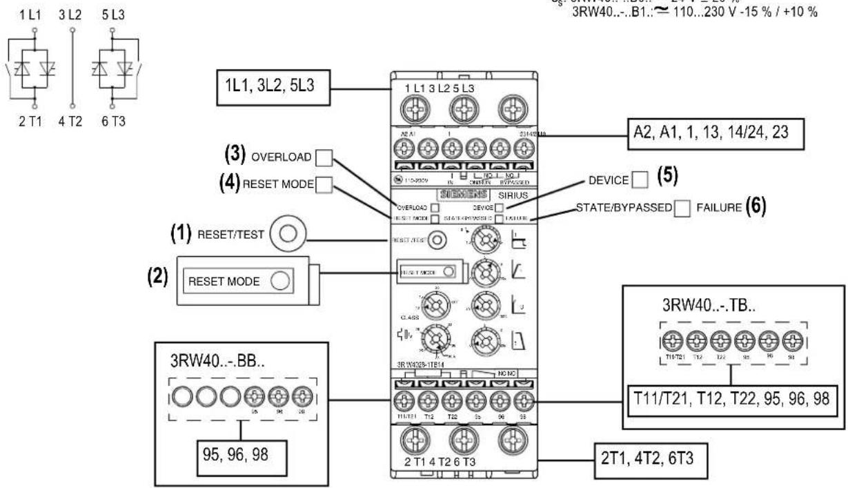
| LED indicators | DEVICE (green/yellow/red), STATE/BYPASSED/FAILURE (green/red), OVERLOAD (red), RESET MODE (yellow/green) |
| Auxiliary contacts | 13-14 (ON/RUN), 24-23 (BYPASSED), 96-95-98 (FAILURE/OVERLOAD) |
| Mounting distance | ≥ 60 mm above, ≥ 40 mm below, 15 mm (3RW40 2) or 30 mm (3RW40 3/4) on sides |
| Cooling | Air, ventilation from bottom to top |
| Ambient temperature | 40 °C (for setting values) |
| Certifications | Certified components required |
| Power supply | Main circuit and control separate |
| Thermistor connection | PTC type A or thermoclick, depending on TB0 version |
Frequently Asked Questions - 3RW4027-1BB14 SIEMENS
User questions about 3RW4027-1BB14 SIEMENS
0 question about this device. Answer the ones you know or ask your own.
Ask a new question about this device
Download the instructions for your Electric starter in PDF format for free! Find your manual 3RW4027-1BB14 - SIEMENS and take your electronic device back in hand. On this page are published all the documents necessary for the use of your device. 3RW4027-1BB14 by SIEMENS.
USER MANUAL 3RW4027-1BB14 SIEMENS
3RW40 3; 3RW40 4: 30 mm [1.18 in]
Read and understand these instructions before installing, operating, or maintaining the equipment.
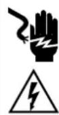
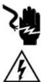
DANGER
Hazardous voltage.
Will cause death or serious injury.
Turn off and lock out all power supplying this device before working on this device.
CAUTION
Reliable functioning of the equipment is only ensured with certified components.
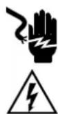
! DANGER
Hazardous voltage.
Will cause death or serious injury.
The terminals of the motor control device must not be touched when it is connected to a voltage in order to prevent electrical shocks or burning. The output terminals of the motor control device are connected to a voltage even when it is in the OFF state.
Stand-alone installation spacings (see soft starter manual for side-by-side installation)
![≥ 60 mm [≥ 2.36 in] 1 3 5 a a 2 4 6 ≥ 40 mm [≥ 1.56 in] a)](/content/2026/04/730518/images/de36552d13d1f469d88d1d545a17e800cfa22f22cb97e7bd8f8e354dbaac395e.jpg)
NOTICE
Please adhere to the specified spacings when installing the device so that sufficient air can circulate for ventilation. The unit is ventilated from bottom to top.
CAUTION
Risk of damage to property.
Ensure that no liquids, dust or conductive parts enter the soft starter.
NOTE
Surrounding air temperature - A rating assigned to open type equipment that refers to the maximum ambient temperature of air immediately surrounding the equipment inside of the ultimate enclosure.
a) 3RW40 2: 15 mm [0.59 in]
3RW40 3; 3RW40 4: 30 mm [1.18 in]
Setpoint values for motor current
Permitted setpoint values for the motor current, dependent on the CLASS setting at 40 °C surrounding air temperature
| I_e [A] I | min [A] I | max [A] CLASS 10 I | max [A] CLASS 15 I | max [A] CLASS 20 | ||
| 3RW40 | 24-... | 12.5 | 5 | 12.5 | 11 10 | |
| 3RW40 | 26-... | 25.3 | 10.3 | 25.3 | 23 | 21 |
| 3RW40 27-... | 32.2 | 17.2 | 32.2 | 30 | 27 | |
| 3RW40 28-... | 38 | 23 | 38 | 34 | 31 | |
| 3RW40 36-... | 45 | 22.5 | 45 | 42 | 38 | |
| 3RW40 37-... | 63 | 25.5 | 63 | 50 | 46 | |
| 3RW40 38-... | 72 | 34.5 | 72 | 56 | 50 | |
| 3RW40 46-... | 80 | 42.5 | 80 | 70 | 64 | |
| 3RW40 47-... | 106 | 46 | 106 | 84 | 77 | |
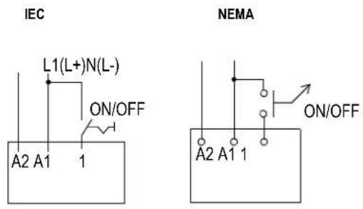
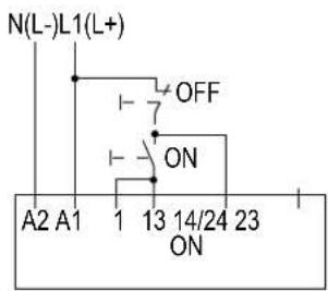
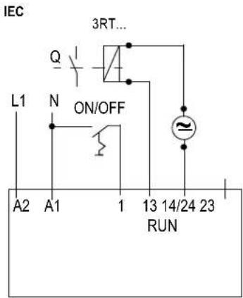
Programming the ON/RUN output 13/14 (factory setting: ON) (Fig. 3 in graphics section)
- Start programming mode: (For the 3RW40 2 device, remove the cover as shown in Figure 2.) Press and hold the "RESET MODE" button (2) for longer than 2 seconds until the LED "DEVICE" (5) flickers green. While pushing the "RESET MODE" button (2), press the "RESET/TEST" button (1) for longer than 1 second until the LED "DEVICE" (5) on the device lights up red.
- Display mode: LED "STATE/BYPASSED/FAILURE" (6) flashes green: ON mode. LED "STATE/BYPASSED/FAILURE" (6) flickers green: RUN mode.
- Change mode: Press the "RESET MODE" (2) button.
- Exit programming mode and save settings: Press and hold the "RESET/TEST" button (1) for longer than 1 second until the LED "DEVICE" (5) lights up green.
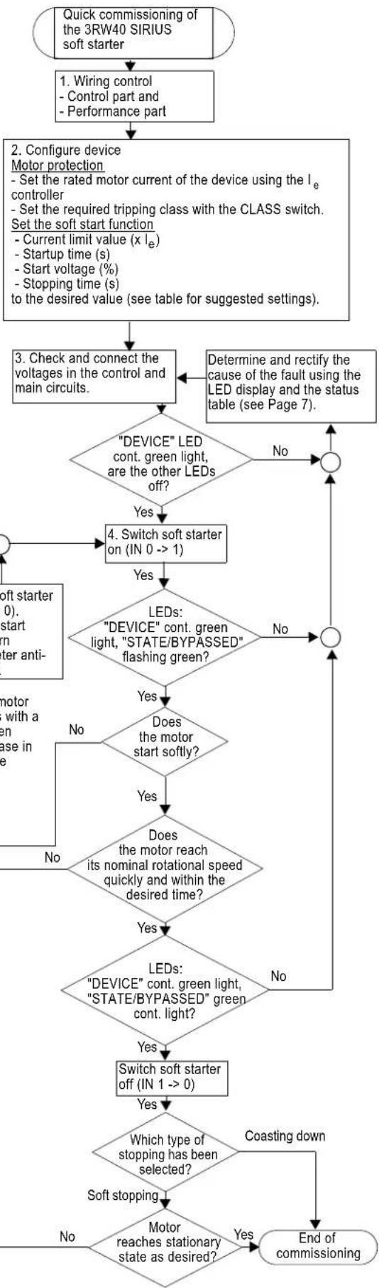
Quick commissioning instructions
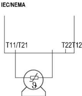
Thermistor connection (3RW40.-.TB0. only)
- Thermoclick connection according to Fig. 6.3 (remove jumper)
- PTC connection type A according to Fig. 6.4 (remove jumper)
CAUTION
Risk of damage to property.
Connection to an unassigned terminal is not permitted.
| Suggested setting Startup parameters | Stopping parameters | |||
| Application | Start voltage %40 100% | Startup time s5 100 20s | Current limit valuex le1.3 | Stopping time s5 100 20s |
| Conveyor belt | 70 10 | 5 x Ie | 5 | |
| Roller conveyor | 60 10 | 5 x Ie | 5 | |
| Compressor | 50 10 | 4 x Ie | 0 | |
| Small fan | 40 10 | 4 x Ie | 0 | |
| Pumps | 40 10 | 4 x Ie | 10 | |
| Hydraulic pump | 40 10 | 4 x Ie | 0 | |
| Stirrers | 40 20 | 4 x Ie | 0 | |
| Milling machines | 40 20 | 4 x Ie | 0 | |
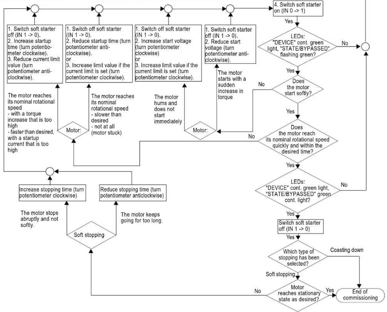
flowchart
graph TD
    A["Switch soft starter off (IN 1 --> 0)."] --> B{Switch off soft starter (IN 1 --> 0).}
    B -->|Yes| C["LEDs: "DEVICE" cont. green light, "STATE/BYPASSED" flashing green?"]
    B -->|No| D["Switch soft starter off (IN 1 --> 0)."]
    C --> E{Does the motor start softly?}
    E -->|Yes| F{Does the motor reach its nominal rotational speed quickly and within the desired time?}
    E -->|No| G["Motor starts with a sudden increase in torque"]
    F -->|Yes| H{LEDs: "DEVICE" cont. green light, "STATE/BYPASSED" green cont. light?}
    F -->|No| I["Switch soft starter off (IN 1 --> 0)"]
    G --> J{Which type of stopping has been selected?}
    J -->|Yes| K["End of commissioning"]
    J -->|No| L["Motor reaches stationary state as desired?"]
    L --> M["Soft stopping"]
    M --> N{Soft stopping}
    N -->|Yes| O["Increase stopping time (turn potentiometer clockwise)"]
    N -->|No| P["Reduce stopping time (turn potentiometer anticlockwise)"]
    O --> Q["The motor stops abruptly and not softly."]
    Q --> R{The motor reaches its nominal rotational speed - slower than desired - not at all (motor stuck)}
    R -->|Yes| S["Motor: The motor reaches its nominal rotational speed - slower than desired - not at all (motor stuck)"]
    R -->|No| T["The motor keeps going for too long."]
    S --> U["The motor reaches its nominal rotational speed - slower than desired - not at all (motor stuck)"]
    T --> V["The motor keeps going for too long."]
    U --> W["The motor reaches its nominal rotational speed - slower than desired - not at all (motor stuck)"]
    V --> X["The motor keeps going for too long."]
    W --> Y["The motor reaches its nominal rotational speed - slower than desired - not at all (motor stuck)"]
    X --> Z["The motor keeps going for too long."]
    Y --> AA["The motor reaches its nominal rotational speed - slower than desired - not at all (motor stuck)"]
    Z --> AB["The motor keeps going for too long."]
    AA --> AC["The motor reaches its nominal rotational speed - slower than desired - not at all (motor stuck)"]
    AB --> AD["The motor keeps going for too long."]
    AC --> AE["The motor reaches its nominal rotational speed - slower than desired - not at all (motor stuck)"]
    AD --> AF["The motor keeps going for too long."]
    AE --> AG["The motor reaches its nominal rotational speed - slower than desired - not at all (motor stuck)"]
    AF --> AH["The motor keeps going for too long."]
    AG --> AI["The motor reaches its nominal rotational speed - slower than desired - not at all (motor stuck)"]
    AH --> AJ["The motor keeps going for too long."]
    AI --> AK["The motor reaches its nominal rotational speed - slower than desired - not at all (motor stuck)"]
    AJ --> AL["The motor keeps going for too long."]
    AK --> AM["The motor reaches its nominal rotational speed - slower than desired - not at all (motor stuck)"]
    AL --> AN["The motor keeps going for too long."]
    AM --> AO["The motor reaches its nominal rotational speed - slower than desired - not at all (motor stuck)"]
    AN --> AP["The motor keeps going for too long."]
    AO --> AQ["The motor reaches its nominal rotational speed - slower than desired - not at all (motor stuck)"]
    AP --> AR["The motor keeps going for too long."]
    AQ --> AS["The motor reaches its nominal rotational speed - slower than desired - not at all (motor stuck)"]
    AR --> AT["The motor keeps going for too long."]
    AS --> AU["The motor reaches its nominal rotational speed - slower than desired - not at all (motor stuck)"]
    AT --> AV["The motor keeps going for too long."]
    AU --> AW["The motor reaches its nominal rotational speed - slower than desired - not at all (motor stuck)"]
    AV --> AX["The motor keeps going for too long."]
    AW --> AY["The motor reaches its nominal rotational speed - slower than desired - not at all (motor stuck)"]
    AX --> AZ["The motor keeps going for too long."]
    AY --> BA["The motor reaches its nominal rotational speed - slower than desired - not at all (motor stuck)"]
    AZ --> BB["The motor keeps going for too long."]
    BA --> BC["The motor reaches its nominal rotational speed - slower than desired - not at all (motor stuck)"]
    BB --> BD["The motor keeps going for too long."]
    BC --> BE["The motor reaches its nominal rotational speed - slower than desired - not at all (motor stuck)"]
    BE --> BF["The motor keeps going for too long."]
    BF --> BG["The motor reaches its nominal rotational speed - slower than desired - not at all (motor stuck)"]
    BG --> BH["The motor keeps going for too long."]
    BH --> BI["The motor reaches its nominal rotational speed - slower than desired - not at all (motor stuck)"]
    BI --> BJ["The motor keeps going for too long."]
    BJ --> BK["The motor reaches its nominal rotational speed - slower than desired - not at all (motor stuck)"]
    BK --> BL["The motor keeps going for too long."]
    BL --> BM["The motor reaches its nominal rotational speed - slower than desired - not at all (motor stuck)"]
    BM --> BN["The motor keeps going for too long."]
    BN --> BO["The motor reaches its nominal rotational speed - slower than desired - not at all (motor stuck)"]
    BO --> BP["The motor keeps going for too long."]
    BP --> BQ["The motor reaches its nominal rotational speed - slower than desired - not at all (motor stuck)"]
flowchart
graph TD
    A["Quick commissioning of the 3RW40 SIRIUS soft starter"] --> B["1. Wiring control<br>- Control part and<br>- Performance part"]
    B --> C["2. Configure device<br>Motor protection<br>- Set the rated motor current of the device using the Iₑ controller<br>- Set the required tripping class with the CLASS switch.<br>Set the soft start function<br>- Current limit value (x Iₑ)<br>- Startup time (s)<br>- Start voltage (%)<br>- Stopping time (s)<br>to the desired value (see table for suggested settings)."]
    C --> D{“DEVICE” LED cont. green light,
are the other LEDs off?}
    D -->|No| E["○"]
    D -->|Yes| F["4. Switch soft starter on (IN 0 --> 1)"]
    F --> G{LEDs:
"DEVICE" cont. green light, "STATE/BYPASSED" flashing green?}
    G -->|No| H["○"]
    G -->|Yes| I{Does the motor start softly?}
    I -->|No| J["Soft starter (0)."]
    I -->|Yes| K{Does the motor reach its nominal rotational speed quickly and within the desired time?}
    K -->|No| L["Motor with a power phase in line"]
    K -->|Yes| M{LEDs:
"DEVICE" cont. green light,
"STATE/BYPASSED" green cont. light?}
    M -->|No| N["End of commissioning"]
    M -->|Yes| O["Switch soft starter off (IN 1 --> 0)"]
    O --> P{Which type of stopping has been selected?}
    P -->|Coasting down| Q["End of commissioning"]
    P -->|No| R["Motor reaches stationary state as desired?"]
    R --> S["End of commissioning"]
Display overview
| LED displays on 3RW40 Auxiliary contacts | |||||||||||
| Soft starter Motor protection | |||||||||||
| 3RW40 | DEVICE (rd/gn/ylw) | STATE / BYPASSED / FAILURE (gn/rd) | OVERLOAD (rd) | RESET MODE (ylw/gn) | 13 14 (ON) | 13 14 (RUN) | 24 23 (BYPASSED) | 96 95 98 FAILURE / OVERLOAD | |||
| U_s=0 | ● | ● | ● | ● | —/_ | —/_ | —/_ | ! | |||
| Operating state | IN | ||||||||||
| OFF | 0 | ○ gn | ● | ● | ● | —/_ | —/_ | —/_ | ! | ||
| Start-up | 1 | ○ gn | ○ gn | ● | ● | —_— | —_— | —/_ | ! | ||
| Bypassed | 1 | ○ gn | ○ gn | ● | ● | —_— | —_— | —_— | ! | ||
| Run-out | 0 | ○ gn | ○ gn | ● | ● | —/_ | —_— | —/_ | ! | ||
| Warning | |||||||||||
| I_e /class setting invalid | ○ gn | ○ gn gn | ○ | ● | ! | ||||||
| Start-up locked, device too warm | ○ ylw | ● | ● | ● | —/_ | —/_ | —/_ | ! | |||
| Error | |||||||||||
| Supply voltage electronics invalid | ● | ○ rd | ● | ● | —/_ | —/_ | —/_ | ! | |||
| Invalid I_e /class setting and IN (0->1) | ○ gn | ○ rd | ○ | ● | —/_ | —/_ | —/_ | ! | |||
| Motor protection switch-off Overload relay / thermistor | ○ gn | ● | ○ | ● | —/_ | —/_ | —/_ | ! | |||
| Thermistor motor protection Wire break / short circuit | ○ gn | ● | ○ | ● | —/_ | —/_ | —/_ | ! | |||
| Thermal overload device | ○ ylw | ○ rd | ● | ● | —/_ | —/_ | —/_ | ! | |||
| - Missing load voltage - Phase failure, no load | ○ gn | ○ rd | ● | ● | —/_ | —/_ | —/_ | ! | |||
| Device fault | ○ rd | ○ rd | ● | ● | —/_ | —/_ | —/_ | ! | |||
| Test function | |||||||||||
| 1)Press TEST for t>5 s | ○ gn | ● | ○ rd | ● | —/_ | —/_ | —/_ | ! | |||
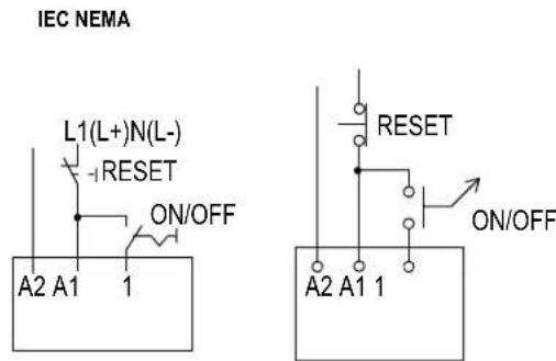
| RESET MODE (press to change) | |||||||||||
| Manual Reset | ● | ● | ● | ● | |||||||
| Auto Reset | ● | ● | ● | ○ ylw | |||||||
| Remote Reset See Fig. 6.2 | ● | ● | ● | ○ gn | |||||||
| LED display | 1) Motor protection shutdown test | ||||||||||
| gn = | ylw = | rd = | |||||||||
| OFF ON flashing flickering green yellow red | |||||||||||
WARNING
Automatic restart.
May result in death, serious injury or damage to property.
The automatic reset mode (RESET MODE) must not be used in applications where an unexpected restart of the motor after the recovery time has elapsed may lead to personal injury or damage to property.
The start command (e.g. by the PLC) must be reset before a reset command, since an automatic restart is executed when a start command is pending after the reset command. This especially applies to motor protection tripping. For safety reasons it is recommended to integrate the group fault output (terminals 95 and 96) into the control.
3RW40 3; 3RW40 4: 30 mm [1.18 in]
3RW40 3; 3RW40 4: 30 mm [1.18 in]
3RW40 3; 3RW40 4: 30 mm [1.18 in]
3RW40 3; 3RW40 4: 30 mm [1.18 in]
3RW40 3; 3RW40 4: 30 mm [1.18 in]
电机电流设定值
4.
- 6.1
6.3
6.5
6.2
line
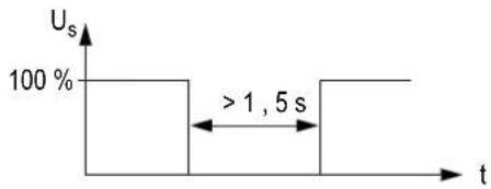
| t | Us (%) | |---|---| | 0 to 1 | 100 | | > 1,5 s | 100 |6.4
NEMA
6.6
IEC
6.7
NEMA
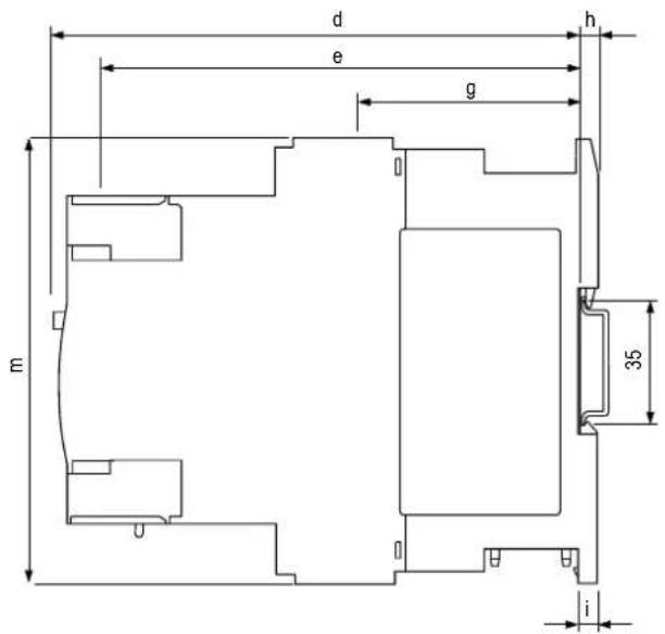
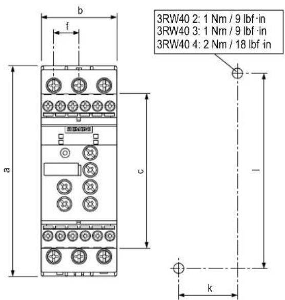
| a | b | c | d | e | f | g | h | i | |||||
| 3RW40 2.-1.... | 125 (4.92) | 45 (1.8) | 92 (3.62) | 149 (5.90) | 126 (5.00) | 14,4 (0.57) | 63 (2.48) | 5 (0.2) | 6,5 (0.26) | 35 (1.38) | 115 (4.53) | 125 (4.92) | |
| 3RW40 2.-2.... | 125 (4.92) | 45 (1.8) | 92 (3.62) | 149 (5.90) | 144 (5.67) | 14,4 (0.57) | 90,5 (3.56) | 5 (0.2) | 6,5 (0.26) | 35 (1.38) | 115 (4.53) | 150 (5.90) | |
| 3RW40 3 | 160 (6.3) | 55 (2.18) | 110 (4.33) | 165 (6.49) | 140 (5.51) | 18 (0.71) | 63 (2.48) | 5 (0.2) | 6,5 (0.26) | 30 (1.18) | 150 (5.91) | 144 (5.67) | |
| 3RW40 4 | 170 (6.7) | 70 (2.76) | 110 (4.33) | 183 (7.20) | 158 (6.22) | 22,5 (0.89) | 85 (3.35) | 5 (0.2) | 10 (0.4) | 60 (2.36) | 160 (6.3) | 160 (6.3) |
mm (inch)